


Carnot Battery Based on Brayton Supercritical CO2 Thermal Machines Using Concentrated Solar Thermal Energy as a Low-Temperature Source
 , , and
Abstract
:1. Introduction
2. Methodology
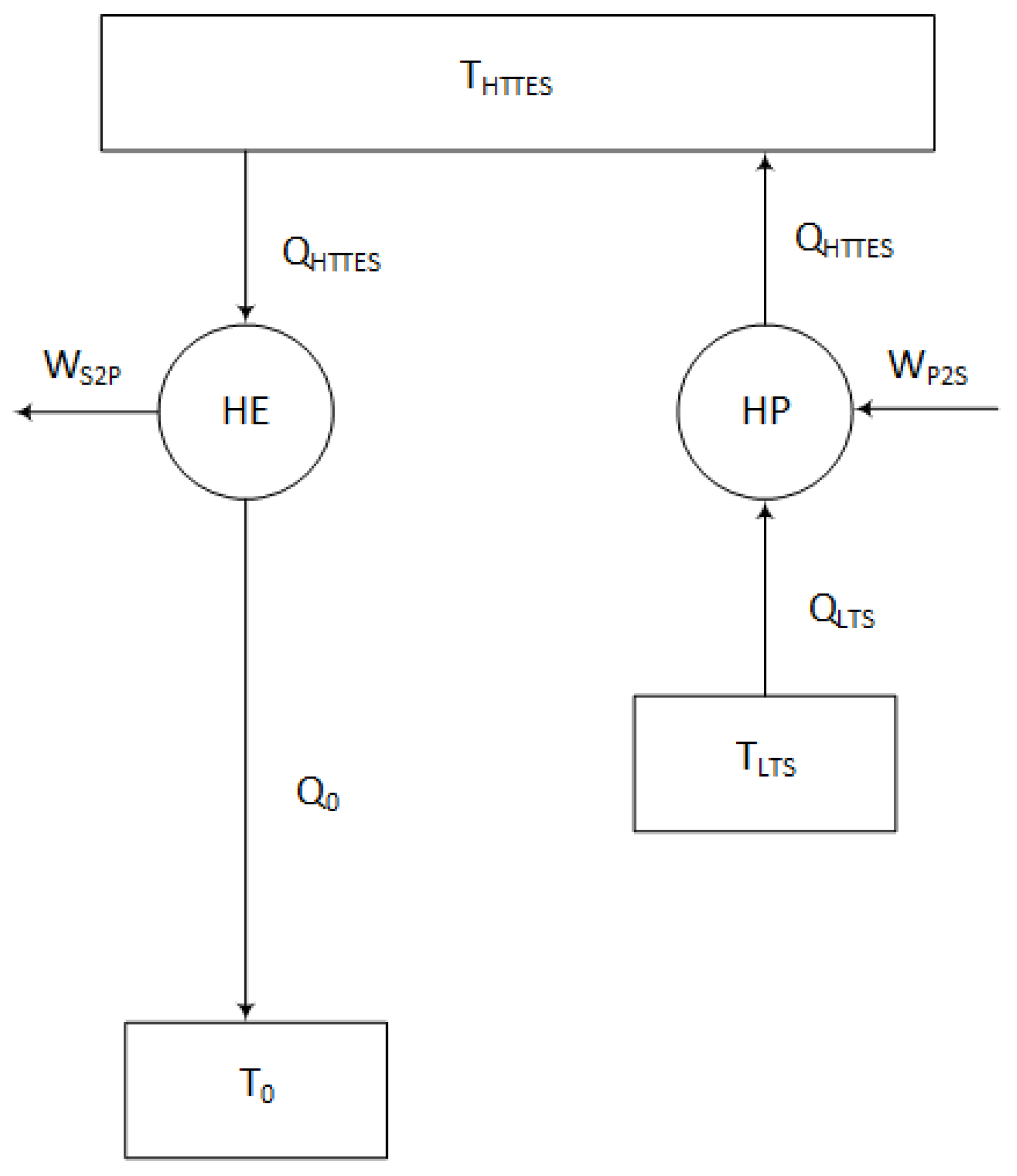
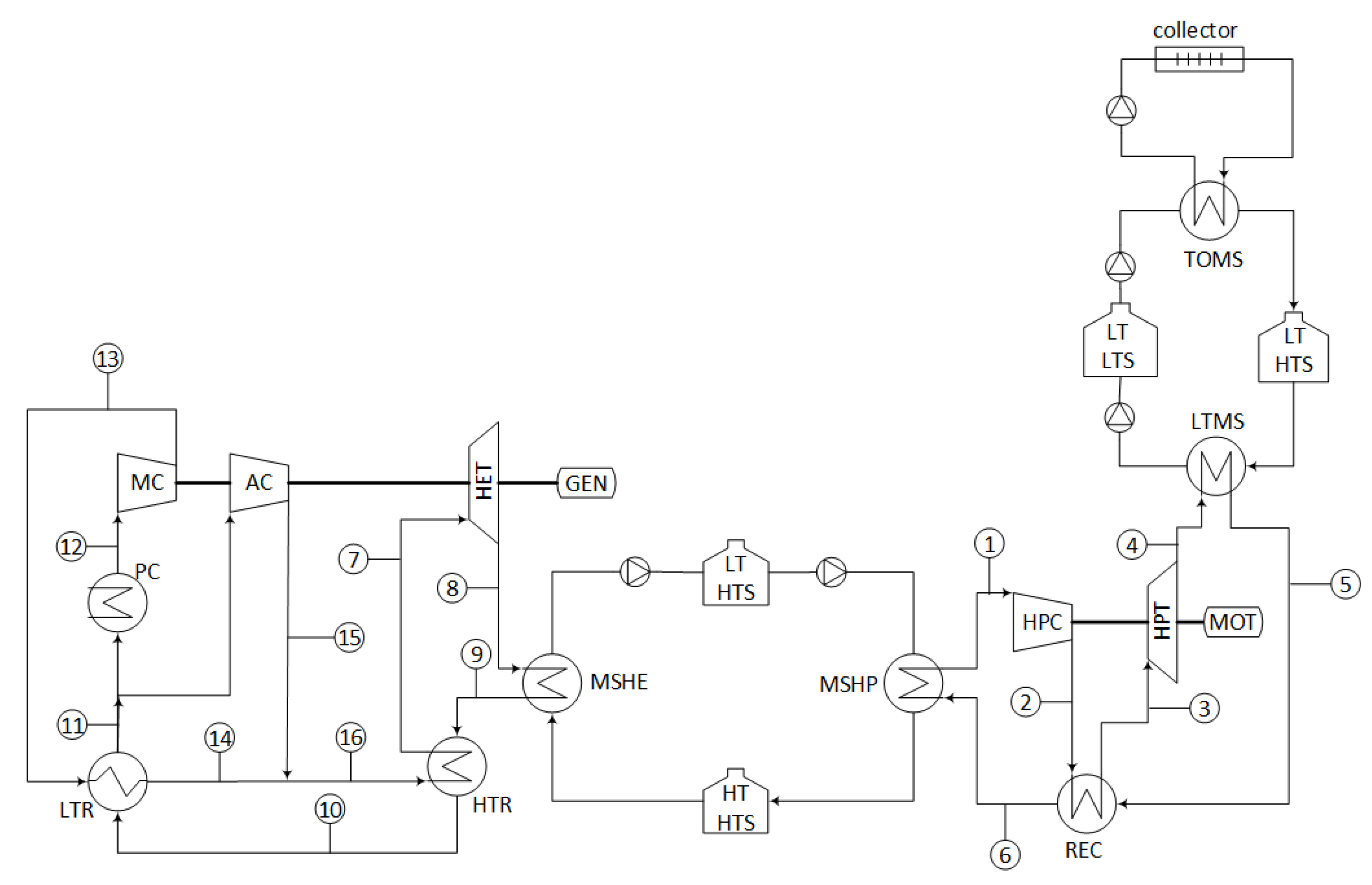
2.1. Concept
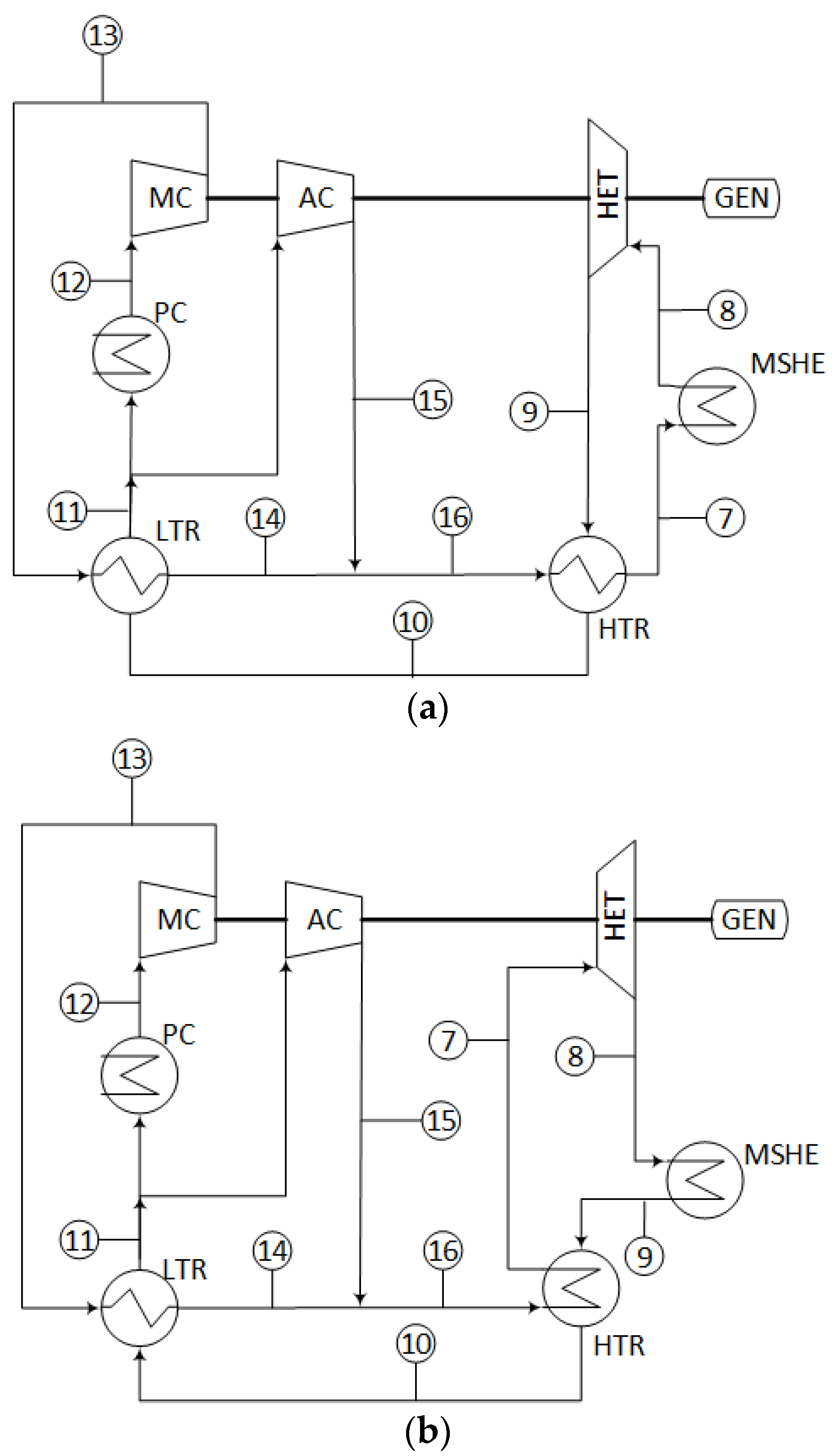
2.2. Heat Engine
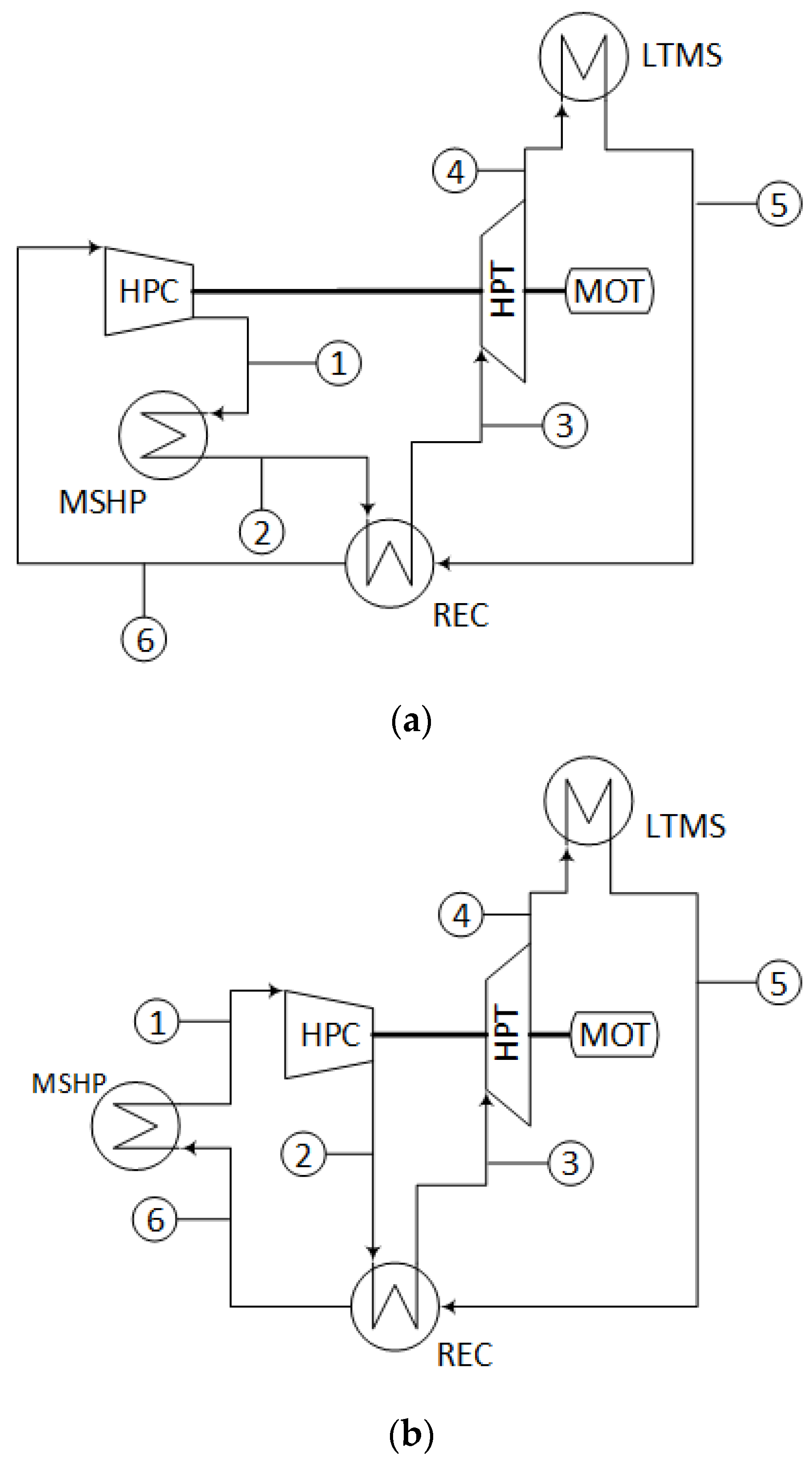
2.3. Heat Pump
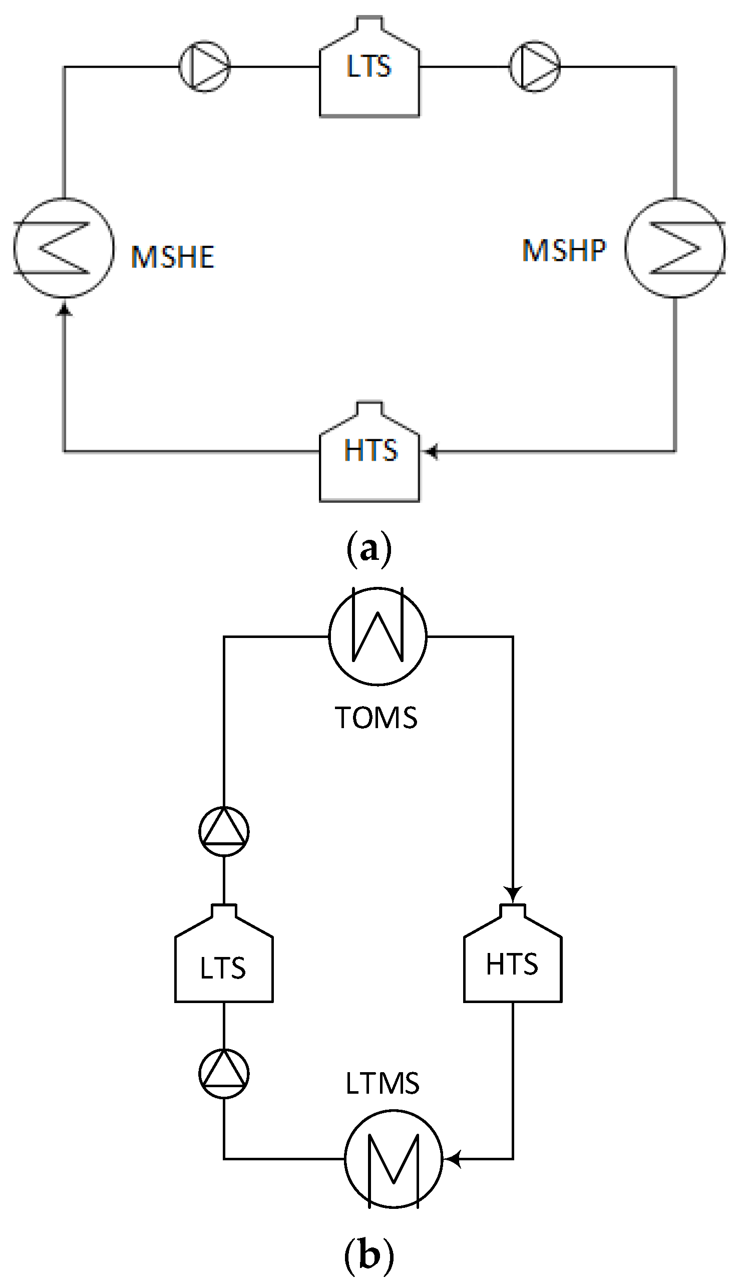
2.4. Molten Salts Loops
2.5. Solar Field
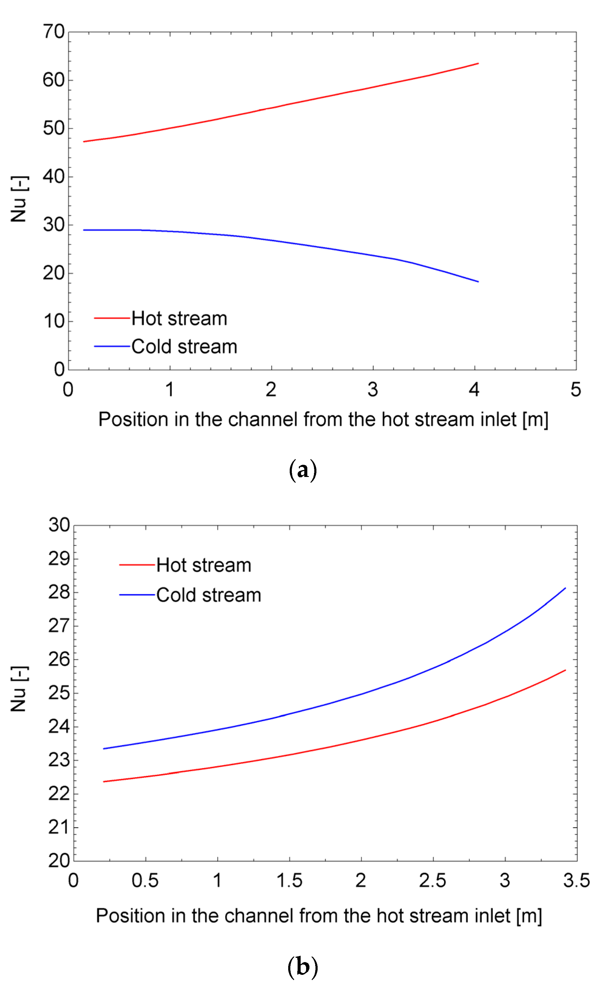
2.6. Sizing of Heat Exchangers
2.7. Economic Model
3. Results
3.1. Complete Layout
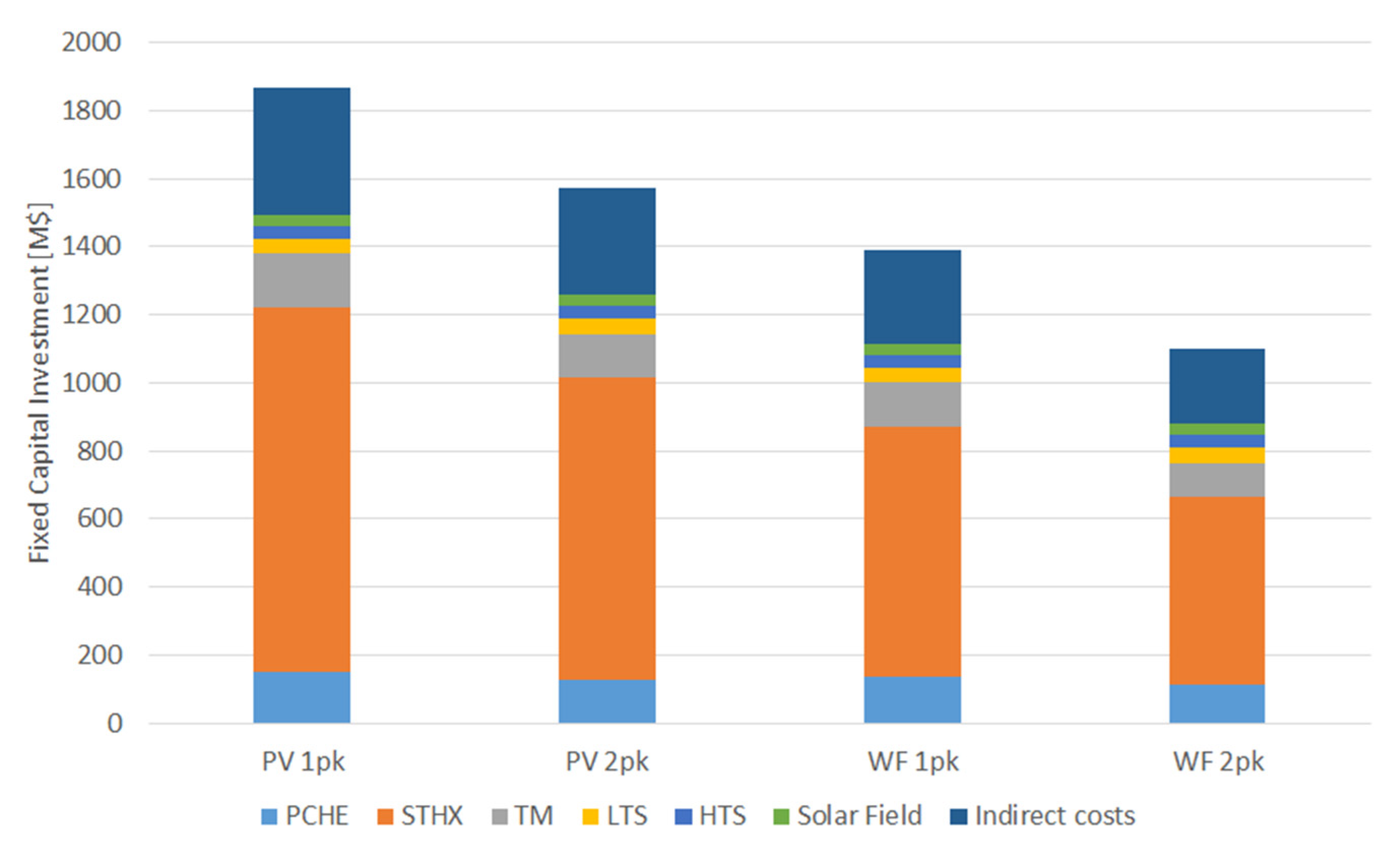
3.2. Performance
4. Discussion and Conclusions
Author Contributions
Funding
Data Availability Statement
Conflicts of Interest
References
- Dumont, O.; Lemort, V. Mapping of performance of pumped thermal energy storage (Carnot battery) using waste heat recovery. Energy 2020, 211, 118963. [Google Scholar] [CrossRef]
- Frate, G.F.; Ferrari, L.; Desideri, U. Rankine Carnot batteries with the integration of thermal energy sources: A review. Energies 2020, 13, 4766. [Google Scholar] [CrossRef]
- Dumont, O.; Frate, G.F.; Pillai, A.; Lecompte, S.; De Paepe, M.; Lemort, V. Carnot battery technology: A state-of-the-art review. J. Energy Storage 2020, 32, 101756. [Google Scholar] [CrossRef]
- Zhang, M.; Shi, L.; Hu, P.; Pei, G.; Shu, G. Carnot battery system integrated with low-grade waste heat recovery: Toward high energy storage efficiency. J. Energy Storage 2023, 57, 106234. [Google Scholar] [CrossRef]
- Zhao, D.; Sun, S.; Alavi, H. Simulation and optimization of a Carnot battery process including a heat pump/organic Rankine cycle with considering the role of the regenerator. Int. J. Low-Carbon Technol. 2022, 17, 870–878. [Google Scholar] [CrossRef]
- Frate, G.F.; Ferrari, L.; Desideri, U. Multi-Criteria Economic Analysis of a Pumped Thermal Electricity Storage (PTES) With Thermal Integration. Front. Energy Res. 2020, 8, 53. [Google Scholar] [CrossRef]
- Eppinger, B.; Muradi, M.; Scharrer, D.; Zigan, L.; Bazan, P.; German, R.; Will, S. Simulation of the part load behavior of combined heat pump-organic rankine cycle systems. Energies 2021, 14, 3870. [Google Scholar] [CrossRef]
- Frate, G.F.; Baccioli, A.; Bernardini, L.; Ferrari, L. Assessment of the off-design performance of a solar thermally-integrated pumped-thermal energy storage. Renew. Energy 2022, 201, 636–650. [Google Scholar] [CrossRef]
- Redelinghuys, L.G.; McGregor, C. Carnot battery application in a parabolic trough concentrating solar power plant: System modelling, validation and analyses on the interplay between stored energies. J. Energy Storage 2023, 60, 106545. [Google Scholar] [CrossRef]
- Zhao, Y.; Song, J.; Liu, M.; Zhao, Y.; Olympios, A.V.; Sapin, P.; Yan, J.; Markides, C.N. Thermo-economic assessments of pumped-thermal electricity storage systems employing sensible heat storage materials. Renew. Energy 2022, 186, 431–456. [Google Scholar] [CrossRef]
- Zhao, Y.-L.; Wang, C.Y.; Liu, M.; Chong, D.T.; Markides, C.N.; Yan, J.J. Configuration Optimization of Carnot Battery Energy Storage System Based on Transcritical Cycles. J. Eng. Thermophys. 2021, 42, 1659–1666. [Google Scholar]
- Steinmann, W.D.; Jockenhöfer, H.; Bauer, D. Thermodynamic Analysis of High-Temperature Carnot Battery Concepts. Energy Technol. 2020, 8, 1900895. [Google Scholar] [CrossRef]
- Frate, G.F.; Pettinari, M.; Di Pino Incognito, E.; Costanzi, R.; Ferrari, L. Dynamic Modelling of a Brayton Ptes System. In Proceedings of the ASME Turbo Expo, Rotterdam, The Netherlands, 13–17 June 2022; Volume 4, p. V004T07A013. [Google Scholar]
- Rindt, K.; Hrdlička, F.; Novotný, V. Preliminary prospects of a Carnot-battery based on a supercritical CO2 Brayton cycle. Acta Polytech. 2021, 61, 644–660. [Google Scholar] [CrossRef]
- Novotny, V.; Basta, V.; Smola, P.; Spale, J. Review of Carnot Battery Technology Commercial Development. Energies 2022, 15, 647. [Google Scholar] [CrossRef]
- Steger, D.; Regensburger, C.; Eppinger, B.; Will, S.; Karl, J.; Schlücker, E. Design aspects of a reversible heat pump—Organic rankine cycle pilot plant for energy storage. Energy 2020, 208, 118216. [Google Scholar] [CrossRef]
- Eppinger, B.; Steger, D.; Regensburger, C.; Karl, J.; Schlücker, E.; Will, S. Carnot battery: Simulation and design of a reversible heat pump-organic Rankine cycle pilot plant. Appl. Energy 2021, 288, 116650. [Google Scholar] [CrossRef]
- Trebilcock, F.; Ramirez, M.; Pascual, C.; Weller, T.; Lecompte, S.; Hassan, A.H. Development of a compressed heat energy storage system prototype, Refrigeration Science and Technology. In Proceedings of the IIR Rankine International Conference on Advances in Cooling, Heating and Power Generation, Rankine 2020, London, UK, 27–21 July 2020; p. 168985. [Google Scholar]
- Blanquiceth, J.; Cardemil, J.M.; Henríquez, M.; Escobar, R. Thermodynamic evaluation of a pumped thermal electricity storage system integrated with large-scale thermal power plants. Renew. Sustain. Energy Rev. 2023, 175, 113134. [Google Scholar] [CrossRef]
- Reyes-Belmonte, M.A.; Guédez, R.; Montes, M.J. Bibliometric análisis on supercritical CO2 power cycles for Concentrating Solar Power applications. Entropy 2021, 23, 1289. [Google Scholar] [CrossRef] [PubMed]
- Dostal, V. A Supercritical Carbon Dioxide Cycle for Next Generation Nuclear Reactors. Doctoral Thesis, Institute of Technology, Cambridge, MA, USA, 2004. [Google Scholar]
- Chen, R.; Romero, M.; González-Aguilar, J.; Rivense, F.; Rao, Z.; Laio, S. Design and off-design performance comparison of supercritical carbon dioxide Brayton cycles for particle-based high temperature concentrating solar power plants. Energy Convers. Manag. 2021, 232, 113870. [Google Scholar] [CrossRef]
- Reyes-Belmonte, M.A.; Sebastián, A.; Romero, M.; González-Aguilar, J. Optimziation of a recompression supercritical carbon dioxide cycle for an innovative central receiver solar power plant. Energy 2016, 112, 17–27. [Google Scholar] [CrossRef]
- Muñoz, M.; Rovira, A.; Montes, M.J. Thermodynamic cycles for solar thermal power plants: A review. WIREs Energy Environ. 2022, 11, e420. [Google Scholar] [CrossRef]
- Vinnemeier, P.; Wirsum, M.; Malpiece, D.; Bove, R. Integration of heat pumps into thermal plants for creation of large-scale electricity storage capacities. Appl. Energy 2016, 184, 506–522. [Google Scholar] [CrossRef]
- Tafur-Escanta, P.; Valencia-Chapi, R.; López-Guillem, M.; Fierros-Peraza, O.; Muñoz-Antón, J. Electrical energy storage using a supercritical CO2 heat pump. Energy Resports 2022, 8, 502–507. [Google Scholar] [CrossRef]
- Aga, V.; Conte, E.; Carroni, R.; Burcker, B.; Ramond, M. Supercritical CO2-based het pump cycle for electrical energy storage for utility scale dispatchable renewable energy power plants. In Proceedings of the 5th International Symposium–Supercritical CO2 Power Cycles, San Antonio, TX, USA, 28–31 March 2016. [Google Scholar]
- Mahdi, Z.; Dersch, J.; Schmitz, P.; Dieckmann, S.; Chico, R.A.; Teixeira, C.; Herrmann, U.; Schwager, C.; Schmitz, M.; Gilen, H.; et al. Technical Assessment of Brayton Cycle Heat Pumps for the Integration in Hybrid PV-CSP Power Plants. AIP Conf. Proc. 2022, 2445, 030014. [Google Scholar]
- Sabharwall, P.; Clark, D.; Glazoff, M.; Zheng, G.; Sridharan, K.; Anderson, M. Advanced heat exchangers development for molten salts. Nucl. Eng. Des. 2014, 280, 42–56. [Google Scholar] [CrossRef]
- Linares, J.I.; Montes, M.J.; Cantizano, A.; Sánchez, C. A novel supercritical CO2 recompression Brayton power cycle for power tower concentrating solar plants. Appl. Energy 2020, 263, 114644. [Google Scholar] [CrossRef]
- Montes, M.J.; Abánades, A.; Martínez-Val, J.M.; Valdés, M. Solar multiple optimization for a solar-only thermal power plant, using oil as heat transfer fluid in the parabolic trough collectors. Sol. Energy 2009, 83, 2165–2176. [Google Scholar] [CrossRef]
- Klein, S.A.; Nellis, G.F. Mastering EES, F-Chart Software, Edition 63. Available online: http://www.fchartsoftware.com/ees/mastering-ees.php (accessed on 1 February 2023).
- Mehos, M.; Turchi, C.; Vidal, J.; Wagner, M.; Ho, Z.; Kolb, W.; Andraka, C.; Kruizenga, A. Concentrating Solar Power Gen3 Demonstration Roadmap; NREL/TP-5500-67464; NREL: Golden, CO, USA, 2017. [Google Scholar]
- Bahamonde-Noriega, J.S. Design Method for S-CO2 Gas Turbine Power Plants. Master’s Dissertation, Delft University of Technology, Delft, The Netherlands, 2012. [Google Scholar]
- Moisseytsev, A.; Sienicki, J.J. Investigation of alternative layouts for the supercritical carbon dioxide Brayton cycle for a sodium-cooled fast reactor. Nucl. Eng. Des. 2009, 239, 1362–1371. [Google Scholar] [CrossRef]
- Available online: https://www.solarpaces-conference.org/ (accessed on 1 February 2023).
- Therminol. 2023. Available online: https://www.therminol.com/heat-transfer-fluids (accessed on 1 February 2023).
- EURO. EuroTrough Project; Final Public Report, European Commission Contract No. JOR3-CT98-00231, Sevilla/Almería/Brussels; EURO: Frankfurt am Main, Germany, 2001. [Google Scholar]
- Serrano, I.P.; Cantizano, A.; Linares, J.I.; Moratilla, B.Y. Modeling and sizing of the heat exchangers of a new supercritical CO2 Brayton power cycle for energy conversion for fusion reactors. Fusion Eng. Des. 2014, 89, 1905–1908. [Google Scholar] [CrossRef]
- Available online: https://www.heatric.com/ (accessed on 1 February 2023).
- Pierres, R.L.; Southall, D.; Osborne, S. Impact of Mechanical Design Issues on Printed Circuit Heat Exchangers. In Proceedings of the 3rd SCO2 Power Cycle Symposium, Boulder, CO, USA, 19–20 September 2019. [Google Scholar]
- Li, X.; Smith, T.; Kininmont, D.; Dewson, S. Materials for Nuclear Diffusion-Bonded Compact Heat Exchangers. In Proceedings of the ICAPP’09, Tokyo, Japan, 10–14 May 2009. [Google Scholar]
- Kakaç, S.; Liu, H.; Pramuanjaroenkij, A. Heat Exchangers: Selection, Rating, and Thermal Design, 3rd ed.; CRC Press: Boca Raton, FL, USA, 2012; ISBN 978-1- 4398-4990-3. [Google Scholar]
- TEMA. Standards of the Tubular Exchanger Manufacturers Association, 8th ed.; TEMA (Tubular Exchanger Manufacturers Association): Tarrytown, NY, USA, 1999. [Google Scholar]
- ASME. Boiling and Pressure Vessel Code; ASME: New York, NY, USA, 2019. [Google Scholar]
- Bejan, A.; Tsatsaronis, G.; Moran, M. Thermal Design & Optimization; Wiley: New York, NY, USA, 1996. [Google Scholar]
- Fleming, D.D.; Conboy, T.M.; Pasch, J.J.; Wright, S.A.; Rochau, G.E.; Fuller, R.L. Scaling Considerations for a Multi-Megawatt Class Supercritical CO2 Brayton Cycle and Commercialization; Sandia Report Sand2013-9106; OSTI: Oak Ridge, TN, USA, 2013. [Google Scholar]
- Southall, D.; Pierres, R.L.; Dewson, S.J. Design considerations for compact heat exchangers. In Proceedings of the ICAPP ’08, Anaheim, CA, USA, 8–12 June 2008. [Google Scholar]
- Driscoll, M.J.; Hejzlar, P. 300 MWe Supercritical CO2 Plant Layout and Design; MIT-GFR-014; MIT Nuclear Engineering Department: Cambridge, MA, USA, 2004. [Google Scholar]
- Purohit, G.P. Estimating costs of shell-and-tube heat exchangers. Chem. Eng. 1983, 22, 56–67. [Google Scholar]
- Kurup, P.; Glynn, S.; Akar, S. Manufacturing cost analysis of advanced parabolic trough collector. AIP Conf. Proc. 2022, 2445, 02006. [Google Scholar]
- Bejan, A. Advanced Engineering Thermodynamics; John Wiley & Sons: New York, NY, USA, 1997. [Google Scholar]
- NREL Concentrating Solar Power Projects in Spain. Available online: https://solarpaces.nrel.gov/by-country/ES (accessed on 1 February 2023).
- Blair, N.; Diorio, N.; Freeman, J.; Gilman, P.; Janzou, S.; Neises, T.; Wagner, M. System Advisor Model (SAM) General Description System Advisor Model; NREL/TP-6A20-70414; OSTI: Oak Ridge, TN, USA, 2018. [Google Scholar]
- Pérez-Pichel, G.; Linares, J.I.; Herranz, L.E.; Moratilla, B.Y. Thermal analysis of supercritical CO2 power cycles: Assessment of their suitability to the forthcoming sodium fast reactors. Nucl. Eng. Des. 2012, 250, 23–34. [Google Scholar] [CrossRef]
- Saranam, V.R.; Paul, B.K. Feasibility of using diffusion bonding for producing hybrid printed circuit heat exchangers for nuclear energy applications. Procedia Manuf. 2018, 26, 560. [Google Scholar] [CrossRef]
- Southall, D.; Dewson, S.J. Innovative compact heat exchangers. In Proceedings of the ICAPP ’10, San Diego, CA, USA, 13–17 June 2010; p. 10300. [Google Scholar]
- International Renewable Energy Agency (IRENA). Renewable Power Generation Costs in 2019; IRENA: Masdar City, United Arab Emirates, 2020; ISBN 978-92-9260-040-2. [Google Scholar]
- Turchi, C.S.; Vidal, J.; Bauer, M. Molten salt power towers operating at 600–650 °C: Salt selection and cost benefits. Sol. Energy 2018, 164, 38–46. [Google Scholar] [CrossRef]


| Technology | Energy Density [kWh/m3] | Energy Cost [$/kWh] | Energy Cost [$/kW] | P2P [%] | Lifetime [Years] |
|---|---|---|---|---|---|
| PHS | 0.5–1.5 | 5–100 | 300–5200 | 65–87 | 30–60 |
| GES | 0.5–1.5 | N/A | N/A | 70–86 | 30–40 |
| CAES | 1–12 | 2–200 | 400–2250 | 40–95 | 20–60 |
| LAES | 50 | 260–530 | 500–3500 | 40–85 | 20–40 |
| Li-Ion B | 300 | 500–2500 | 270–1500 | 85–95 | 5–15 |
| Flow B | 16–60 | 120–1000 | 175–10,000 | 57–85 | 5–15 |
| PTES | 0.25–6.9 | 62–107 | 533–627 | 70–80 | 25–30 |
| Number of loops in the solar field | 78 |
| Number of collectors per loop | 4 |
| Number of modules per collector | 10 |
| Length of every module (m) | 12.27 |
| Absorber tube outer diameter (m) | 0.07 |
| Absorber tube inner diameter (m) | 0.065 |
| Glass envelope outer diameter (m) | 0.115 |
| Glass envelope inner diameter (m) | 0.109 |
| Intercept factor | 0.92 |
| Mirror reflectivity | 0.92 |
| Glass transmissivity | 0.945 |
| Solar absorptivity | 0.94 |
| Peak optical efficiency | 0.75 |
| Mass Flow per loop (kg/s) | 7.6 |
| Inlet/Outlet HTF temperature (°C) | 300/390 |
| Inlet Pressure (bar) | 20 |
| Heat gain per loop (MWth) | 1.6732 |
| Heat loss per loop (kWth) | 158.56 |
| Pressure drop per loop (bar) | 4.1438 |
| Optical efficiency (%) | 71.99 |
| Thermal efficiency (%) | 91.34 |
| Point | Pressure (bar) | Temperature (°C) | Enthalpy (kJ/kg) |
|---|---|---|---|
| 1 | 85.00 | 415.0 | 377.28 |
| 2 | 300.0 | 604.1 | 590.78 |
| 3 | 299.5 | 389.2 | 318.67 |
| 4 | 86.50 | 256.0 | 194.39 |
| 5 | 86.00 | 370.0 | 324.89 |
| 6 | 85.50 | 599.1 | 597.00 |
| Point | Pressure (bar) | Temperature (°C) | Enthalpy (kJ/kg) |
|---|---|---|---|
| 7 | 299.0 | 532.9 | 500.51 |
| 8 | 87.00 | 385.4 | 342.50 |
| 9 | 86.50 | 579.1 | 572.58 |
| 10 | 86.00 | 207.2 | 138.99 |
| 11 | 85.50 | 82.02 | −17.394 |
| 12 | 85.00 | 35.00 | −197.94 |
| 13 | 300.0 | 76.52 | −163.33 |
| 14 | 299.5 | 201.7 | 66.166 |
| 15 | 299.5 | 203.3 | 68.548 |
| 16 | 299.5 | 202.2 | 66.925 |
| Loop | Hot Tank Temperature (HT) (°C) | Cold Tank Temperature (LT) (°C) |
|---|---|---|
| High temperature (HTS) | 589 | 405 |
| Low temperature (LTS) | 380 | 290 |
| Component | Heat Duty or Power (MW) | Mass Flow Rate (kg/s) |
|---|---|---|
| Compressor (HPC) | 209 PM | 978 PM |
| Turbine (HPT) | 122 PM | 978 PM |
| Motor (MOT) | 87 PM | --- |
| CO2/CO2 (REC) | 266 PM | 978 PM/978 PM |
| Molten salts/CO2 (LTMS) | 128 PM | 941 PM/978 PM |
| CO2/Molten salts (MSHP) | 215 PM | 978 PM/761 PM |
| Component | Heat Duty or Power (MW) | Mass Flow Rate (kg/s) |
|---|---|---|
| Main Compressor (MC) | 22 EM | 637 EM |
| Auxiliary Compressor (AC) | 26 EM | 297 EM |
| Turbine (HET) | 148 EM | 934 EM |
| Generator (GEN) | 100 EM | --- |
| CO2/CO2 (HTR) | 405 EM | 934 EM/934 EM |
| CO2/CO2 (LTR) | 146 EM | 934 EM/637 EM |
| Molten salts/CO2 (MSHE) | 215 EM | 761 EM/934 EM |
| CO2/Water (PC) | 115 EM | 637 EM/5502 EM |
| Surplus Origin | Hch | Demand Profile | Hdisch | PM | EM | Charge Power (MW) | Discharge Power (MW) |
|---|---|---|---|---|---|---|---|
| PV | 3 | 1 pk | 3 | 2 | 2 | 174 | 200 |
| 3 | 2 pk | 6 | 2 | 1 | 174 | 100 | |
| WF | 6 | 1 pk | 3 | 1 | 2 | 87 | 200 |
| 6 | 2 pk | 6 | 1 | 1 | 87 | 100 |
| Component | Profile | Heat Duty (MW) | Height (m) | Number of Modules | On-Site Cost (USD M2020) |
|---|---|---|---|---|---|
| REC | WF | 266 | 3.42 | 128 | 43.9 |
| PV | 532 | 3.42 | 256 | 57.9 | |
| HTR | 2 pk | 405 | 2.38 | 59 | 32.2 |
| 1 pk | 810 | 2.38 | 118 | 42.5 | |
| LTR | 2 pk | 146 | 4.03 | 99 | 27.5 |
| 1 pk | 292 | 4.03 | 198 | 36.2 | |
| PC | 2 pk | 115 | 0.54 | 10 | 10.8 |
| 1 pk | 230 | 0.54 | 20 | 14.2 |
| Component | Profile | Heat Duty (MW) | Length (m) | Shell Diameter (m) | Number of Units | On-Site Cost per Unit (USD M2020) |
|---|---|---|---|---|---|---|
| TOMS | All | 128 | 30.2 | 3.18 | 1 | 35.6 |
| LTMS | WF | 128 | 14.8 | 3.62 | 1 | 67.6 |
| PV | 256 | 14.8 | 3.62 | 2 | 135 | |
| MSHP | WF | 215 | 39.5 | 4.26 | 1 | 286 |
| PV | 430 | 39.5 | 4.26 | 2 | 572 | |
| MSHE | 2 pk | 215 | 30.2 | 4.05 | 1 | 191 |
| 1 pk | 430 | 30.2 | 4.05 | 2 | 382 |
| Cycle | Type | On-Site Cost (USD M2020) |
|---|---|---|
| HP | WF | 20.4 |
| PV | 32.7 | |
| HE | 2 pk | 22.4 |
| 1 pk | 35.9 |
| Component | Energy Stored (MWh) | Salt Inventory (ton) | Direct Costs (USD M2020) |
|---|---|---|---|
| LTS | 768 | 20,393 | 44.0 |
| HTS | 1290 | 16,462 | 37.0 |
| Solar Field | --- | --- | 32.5 |
| Surplus Origin | Demand Profile | Discharge Power (MW) | Discharge Energy (MWh) | FCI (USD M2020) | LCOS (USD2020/MWh) |
|---|---|---|---|---|---|
| PV | 1 pk | 200 | 600 | 1865 | 639 |
| 2 pk | 100 | 600 | 1571 | 538 | |
| WF | 1 pk | 200 | 600 | 1392 | 477 |
| 2 pk | 100 | 600 | 1098 | 376 |
Disclaimer/Publisher’s Note: The statements, opinions and data contained in all publications are solely those of the individual author(s) and contributor(s) and not of MDPI and/or the editor(s). MDPI and/or the editor(s) disclaim responsibility for any injury to people or property resulting from any ideas, methods, instructions or products referred to in the content. |
© 2023 by the authors. Licensee MDPI, Basel, Switzerland. This article is an open access article distributed under the terms and conditions of the Creative Commons Attribution (CC BY) license (https://creativecommons.org/licenses/by/4.0/).
Share and Cite
Linares, J.I.; Martín-Colino, A.; Arenas, E.; Montes, M.J.; Cantizano, A.; Pérez-Domínguez, J.R. Carnot Battery Based on Brayton Supercritical CO2 Thermal Machines Using Concentrated Solar Thermal Energy as a Low-Temperature Source. Energies 2023, 16, 3871. https://doi.org/10.3390/en16093871
Linares JI, Martín-Colino A, Arenas E, Montes MJ, Cantizano A, Pérez-Domínguez JR. Carnot Battery Based on Brayton Supercritical CO2 Thermal Machines Using Concentrated Solar Thermal Energy as a Low-Temperature Source. Energies. 2023; 16(9):3871. https://doi.org/10.3390/en16093871
Chicago/Turabian StyleLinares, José Ignacio, Arturo Martín-Colino, Eva Arenas, María José Montes, Alexis Cantizano, and José Rubén Pérez-Domínguez. 2023. "Carnot Battery Based on Brayton Supercritical CO2 Thermal Machines Using Concentrated Solar Thermal Energy as a Low-Temperature Source" Energies 16, no. 9: 3871. https://doi.org/10.3390/en16093871