Article

Frequency Regulation Strategy of Two-Area Microgrid System with Electric Vehicle Support Using Novel Fuzzy-Based Dual-Stage Controller and Modified Dragonfly Algorithm

1
Electrical Engineering, Government Women Engineering College, Ajmer 305002, Rajasthan, India
2
Department of Electronics and Computer Science, Koszalin University of Technology, 75-453 Koszalin, Poland
3
Department of Electrical Engineering, Government Engineering College, Bikaner 334004, Rajasthan, India
4
Department of Electrical Engineering, Baba Hira Singh Bhattal Institute of Engineering and Technology, Lehragaga 148031, Punjab, India
*
Author to whom correspondence should be addressed.
Energies 2023, 16(8), 3407; https://doi.org/10.3390/en16083407
Submission received: 8 February 2023 / Revised: 3 April 2023 / Accepted: 10 April 2023 / Published: 12 April 2023
(This article belongs to the Special Issue Coherent Security Planning for Power Systems)

Abstract

:
Energy in microgrids (MGs) can now be generated from a variety of renewable sources, but their effective and sustainable use is dependent on electrical energy storage (EES) systems. Consequently, the expansion of MGs is greatly reliant on EES systems. The high infiltration of electric vehicles (EVs) causes some problems for the smooth functioning of the electric power system. However, EVs are also able to offer ancillary services, such as energy storage, to power systems. The research presented in this paper aims to develop a novel frequency regulation (FR) approach for biogas diesel engines (wind), the organic Rankine cycle (ORC), and solar-based two-area islanded microgrids with EVs in both areas. This article discusses the introduction of a fuzzy logic controller (FLC) for FR with scaled factors configured as proportional integral (PI) and proportional derivative with filter (PDF), i.e., a FLC-SF-PI-PDF controller. A recently created modified dragonfly algorithm is used to determine the best values for the controller parameters. To justify the effectiveness of the proposed controller with the presence of EVs, the execution of the proposed controller is associated with and without the presence of EVs. This research also looks at the different uncertain conditions, non-linearities, and eigenvalue stability analysis to validate the supremacy of the proposed approach.

1. Introduction

Due to its numerous advantages in remote areas, the increasing use of distributed generation in the form of microgrids (MGs) has become very popular in recent years [1]. The main advantage of such MGs is that they are able to continuously meet energy needs at a low cost. A microgrid is capable of functioning in stand-alone and grid-connected modes [2]. When connected to the grid, the microgrid can provide grid ancillary services [3]. In stand-alone mode, the real and reactive power produced from sources and electrical energy storage (EES) devices in the MG must be in balance with the demand of the local load. The hybrid isolated microgrid (IMG) system is a state-of-the-art system consisting of traditional and modern energy sources, such as diesel generators (DGs), biodiesel generation (BDG), renewable energy sources (solar, wind, geothermal, and tidal), and energy storage systems (batteries) [4]. Hybrid systems can provide numerous benefits, including fuel savings, lower emissions, and increased system reliability and capacity. Despite these benefits, some issues such as the stochastic nature of wind and solar RESs should be addressed for the smooth and reliable operation of IMGs. The nature-dependent and stochastic nature of RESs make balancing energy demand and supply extremely difficult, and this can result in substantial power and frequency oscillations. As a result, to keep frequency variations within tolerable limits, a well-designed frequency regulation scheme is required, particularly when the MG is operating in islanded mode [5]. Numerous control strategies were established in the past to advance frequency regulation performance. Traditional PI and PID controllers are extensively applied in FR schemes due to their simple implementation and design [6,7,8]. Mouth-search optimization (MSO) has been used to optimize the gains of the PID with a filter (PIDF) controller [9] to enhance the frequency response under various uncertainties. The PIDF controller is an advanced version of the PID which contains a low-pass filter on the derivative part to improve the response of the test system. The filter can help to suppress the noise of the error signal. Furthermore in the literature, various optimization techniques were deployed to optimize PID controller gains, such as firefly optimization [10], JAYA algorithm [11], and teaching and learning-based optimization [12]. Meanwhile, load frequency control (LFC) for decentralized systems is deployed in [13] to regulate the frequency of a multi-area power system based on quasi-oppositional harmony search optimization (QOHS). In addition, a fractional-order (FO) PID (FOPID) regulator was deployed to resolve LFC issues in multi-area systems [14,15]. PID, PIDN, and PI-(1 + PD) controllers have been considered for an independent hybrid maritime MG for LFC. Furthermore, a recent grasshopper algorithm has been used to optimize the controller parameters. The results were also compared with existing controllers and optimization techniques [16]. A social-spider optimizer was used in two-area MGs to fine-tune PID gains for frequency regulation. Furthermore, battery energy storage (BES) and super magnetic energy storage systems (SMESs) are used for short-term backup needs. A diesel unit is used as a cushion to take care of wind and solar variation [17]. A dual-stage modified African buffalo optimization (MABO)-tuned PI-PDF controller is proposed for frequency regulation of a hybrid microgrid. Furthermore, a novel bull-lion optimization-based PI-PDF controller was proposed for frequency stabilization of diverse-source hybrid power. The control technique proposed in the study is compared with other existing techniques, i.e., African buffalo optimization-based PIDF, correct moth search optimization-based PIDF, MABO-based PIDF, and MABO-based PIDF-PDF. The proposed MABO-based dual-stage PI-PDF techniques outperform the other compared techniques. However, there are certain limits to optimizing the parameters of the controller [18]. Few research studies have recommended implementing fuzzy logic controllers (FLCs) with traditional controllers to enhance overall system performance [19,20]. Various optimization techniques have been used in the literature to tune the gains of the fuzzy-based controller, such as biography-based optimization [21], marine predator algorithm [22], grasshopper optimization [23], multi-verse optimizer [24], and self-adaptive modified bat algorithm [25]. Meanwhile, in [26], a quasi-opposition-based equilibrium optimizer (QOEO)-optimized fuzzy fractional order PI + PID (FFOPI + PID) regulator is deployed for frequency stabilization in restructured power systems. Furthermore, the genetic-algorithm-optimized fuzzy-PID controller was used to regulate the frequency of multi-source power systems. In islanded MGs, a neuro-fuzzy (ANFIS)-based controller has been deployed for LFC issues. The controller parameters were tuned using NSGA-II algorithms for ANFIS training [27]. A fractional order fuzzy-PID controller has been deployed for islanded MG for frequency control. Electric vehicle battery storage is also deployed for power balance. A modified black-hole optimization algorithm (MBHA) is used for the optimization of controller gains. Real-world data on solar and wind were considered for the proposed system [28]. A hybrid control strategy consists of fuzzy logic, and a non-linear sliding mode (NL-SLM) control is proposed for the hybrid renewable power system. An imperialist competitive algorithm (ICA) is used to obtain optimal gains of the controller. The NL-SMC is applied at the load side and FLC is used to regulate the error signal. However, high-frequency oscillation is present in the system [29]. A fuzzy gain scheduled PI (FGPI) controller is proposed for frequency stabilization in two-area power systems. In the proposed FGPI controller, Mamdani fuzzy inference was taken, and the ranges of the controller gains were selected differently to improve the response of the power system [30]. The output scaling factor (SF)-tuned fuzzy conventional controller to enhance the AGC behavior of two-area power systems is proposed in [31]. The grasshopper optimization algorithm (GOA)-cascaded fuzzy PD-PI control strategy is proposed for frequency stabilization of MAPS. It uses fuzzy logic for the controller, has two inputs and a single output, and takes the same range for each input and output. Such an arrangement is easy to implement but it only limits the error signal and does not provide proper input to each factor of the controller. GOA is used to tune parameters of controller [32]. Similarly, ICA is used to tune the output SF of the fuzzy proportional integral (FPI) controller. A novel fuzzy 1 + proportional + derivative-tilt + integral (F1PD-TI) controller is used for AGC of hybrid power systems that consist of renewable energy sources based on fuel cells, solar thermal power, and wind power. It also designed the fuzzy 49 rules base for two inputs and a single output. Furthermore, the salp swarm algorithm (SSA) is used to tune the tunable parameters of the controller [33]. In addition, a fuzzy logic integral controller and SMES unit-based control strategy is proposed for isolated microgrids to regulate frequency [34]. Due to the presence of stochastic renewable production, the load frequency control (LFC) problem in an isolated microgrid with low inertia system components becomes more difficult. In an isolated microgrid, the diesel generator participates in LFC and functions as the primary generating unit. Because of the wide geographic distribution of the microgrid, communication delays during the interchange of control and measurement signals at the load frequency controller have an impact on the LFC system. The literature either ignores these communication delays, which were computed using estimation models, or treats them as constants at all nodes. This work presents an IEC-61850-based communication model to close the research gap by estimating actual communication delays between microgrid units. Furthermore, a dual-stage controller PI-(1 + PD) controller is proposed for the isolated microgrid [35].
The stochastic and nature-dependent behavior of RESs does not provide smooth and continuous power to the microgrid. As a result, sometimes an abundant amount of energy is available from RESs and there are times when energy from RESs is not available to fulfill the energy requirements of the MG. Therefore, EESs offer a significant role in the reliable and smooth operation of MGs. As a result, further evolution of MGs relies greatly on energy storage systems. Energy storing devices store excessive energy from RESs and provide it back to the grid when required. Different types of electrical energy storage systems are available and used in previous works, such as batteries [2], flywheel [3], ultra-capacitors [4], redox flow batteries (RFBs) [5], capacitive energy storage (CES) [6] units, and hybrid EESs [36]. Furthermore, advancement in the vehicle-to-grid connection leads to the use of the electric vehicles for emergency backup when power shortages in the grid occurred. The electric vehicle can be considered a portable energy storage device. In [37], the EV is used for the reliable operation of a multi-area restructured power system. A two-area renewable integrated deregulated power system and grid-connected EVs are considered for frequency regulation using a brain emotional learning-based intelligent controller (BELBIC) [38]. The penetration of plug-in electric vehicles (PEVs) in power systems is increasing day by day across the world. Therefore, power systems face new challenges and opportunities. EVs have the potential to provide ancillary services to power systems. An aggregated model of PEVs has been presented using statistical data [39]. Another unique form of adjustable load is plug-in electric vehicles (PEVs). These vehicles, unlike other regulated loads, can be linked to outlets anywhere and at any time, increasing the grid’s spatial and temporal diversity and uncertainty. Furthermore, PEVs with vehicle-to-grid (V2G) technology can send energy right back into the distribution network, resulting in a reverse flow and complicating energy management procedures.

1.1. Motivation

It can be summarized from the above discussion that controllers, energy storage devices, and EVs play a vital role in limiting the frequency deviation of autonomous microgrid systems to the desired range. Frequency regulation of microgrid systems is very important to maintain robust and reliable operations. Two microgrids can be connected through a tie line and they can exchange power with each other in case of emergency conditions. Interconnection of MGs can resolve the issues related to reliable, cost-effective, and sustainable electricity supply by providing a coordinated operation of individual networks. Therefore, the interconnection of MGs encourages the construction of isolated MG interconnected systems to meet the load request of remote areas where grid integration is still not possible. Therefore, in this study, a two-area interconnected microgrid system is proposed, which consists of RESs (biogas diesel engine, wind, and solar) and EESs (RFB, CES, and EVs). Although energy storage devices play a key role in the reliable and smooth operation of microgrids, there is a dire need to design an intelligent controller for an isolated microgrid that can achieve the set objectives and perform robustly in real-world applications.

1.2. Research Contribution

The major contributions of the paper are as follows:
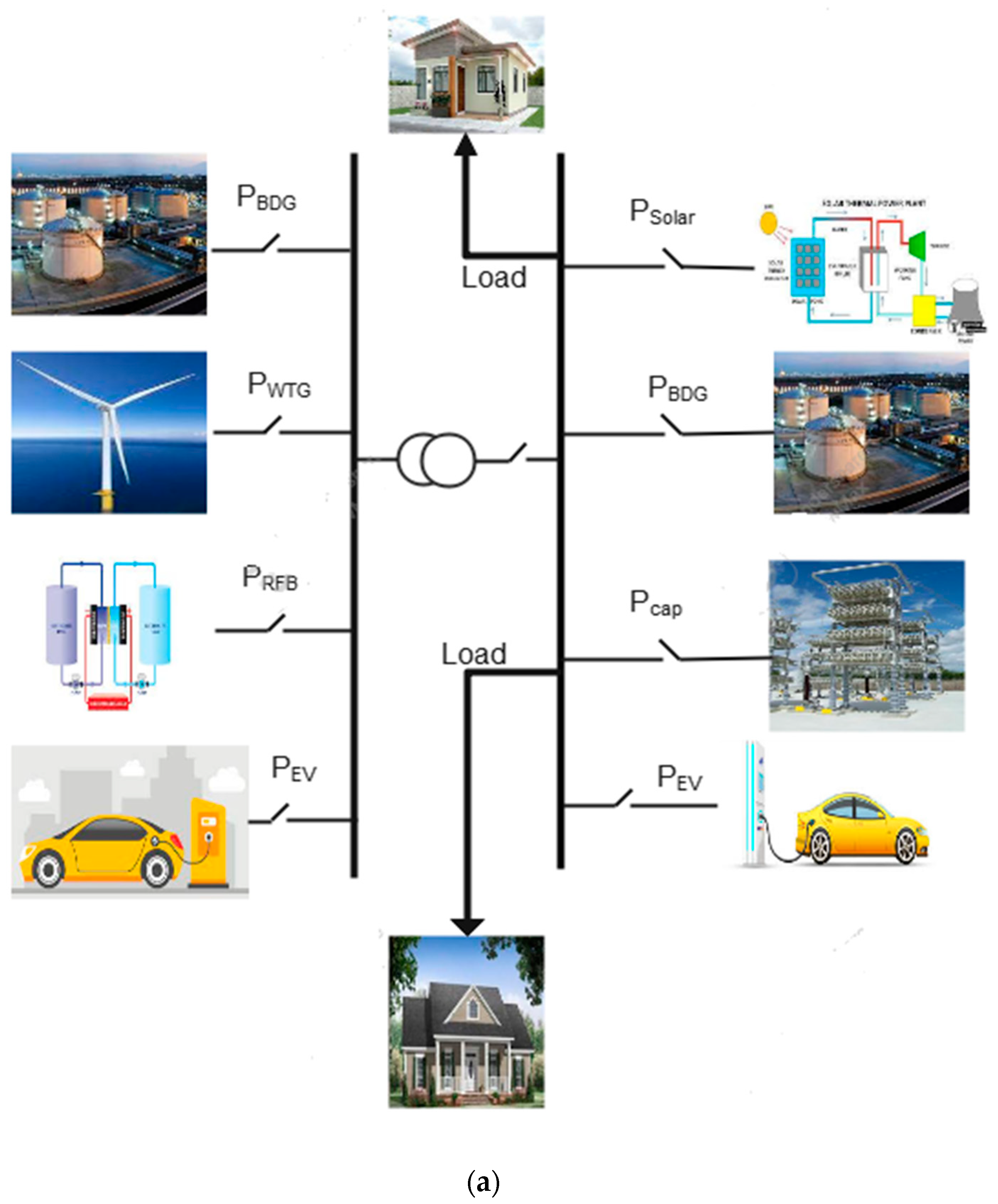
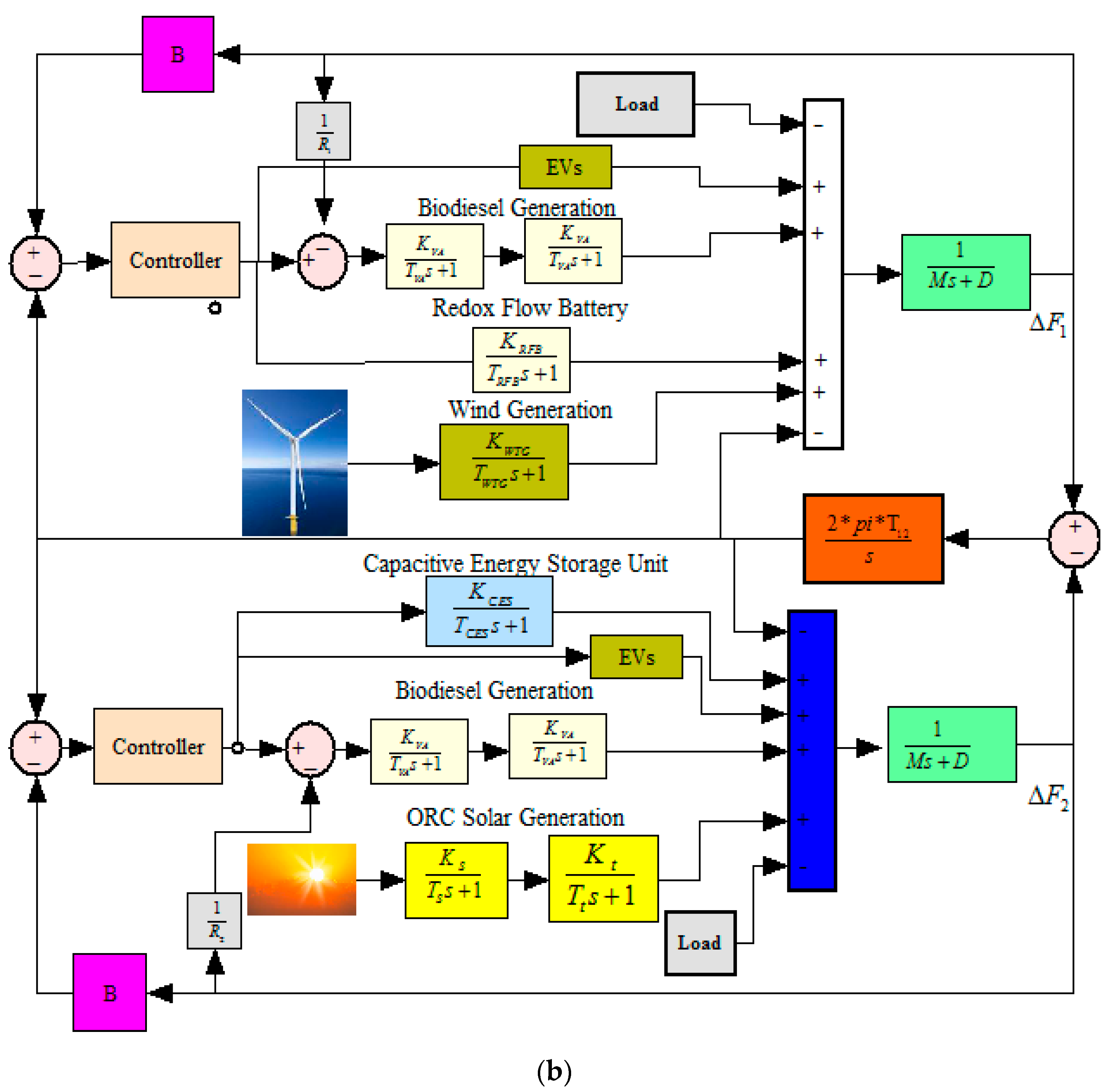
  • A wind, solar, and biodiesel engine-based two-area isolated microgrid system (IMGS) is developed to perform the proposed research work.
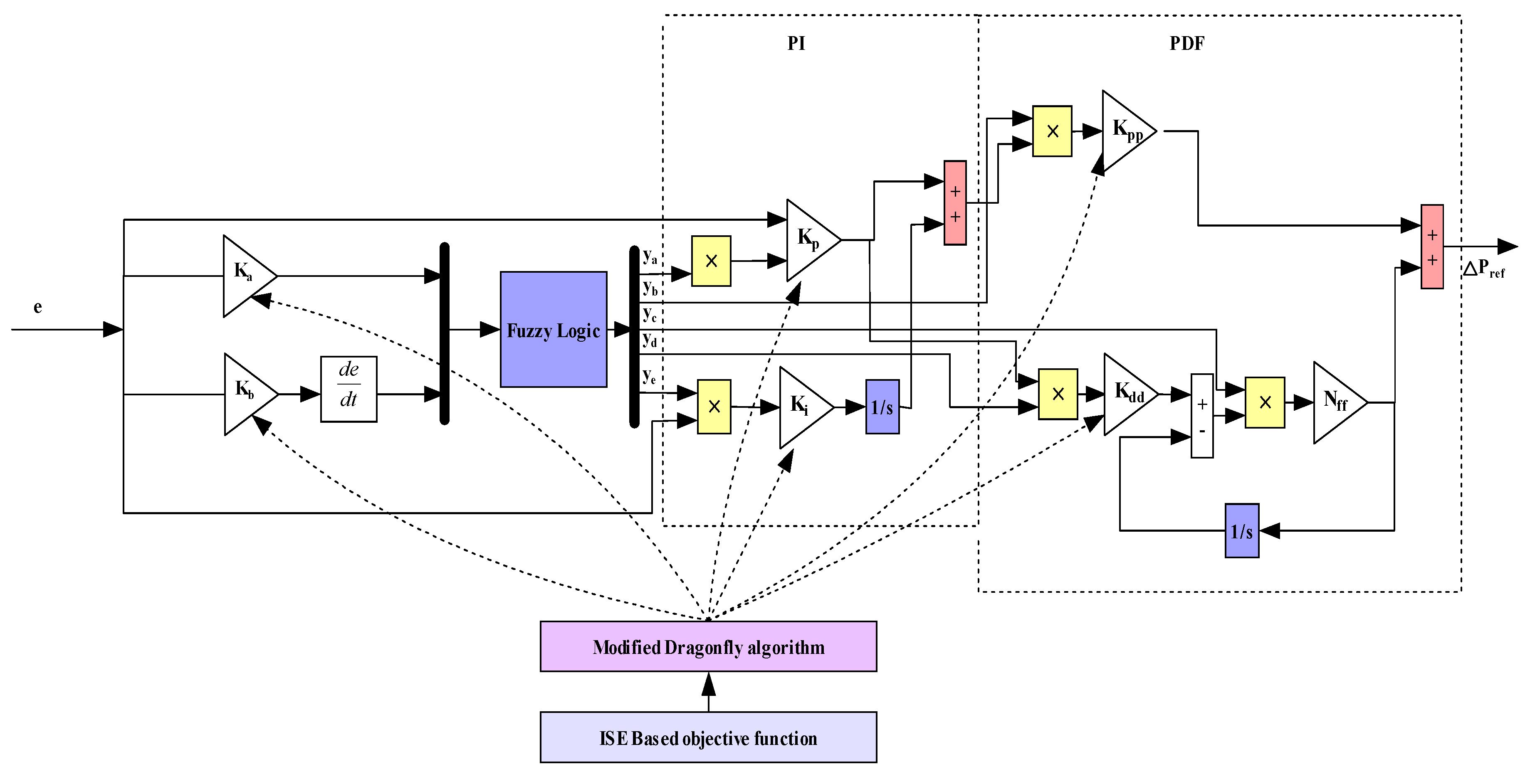
  • Furthermore, a novel fuzzy-having modified PI-PDF scaled factor configuration i.e., a FLC-SF-PI-PDF controller, has been designed to improve the frequency regulation of the proposed MG.
  • Modified dragon-fly optimization (MDA) has been deployed to find the optimal value of the gains of the proposed controller.
  • Furthermore, the research also extends to measuring the consequence of several types of load, wind speed, and solar irradiance variation, such as step perturbation (SLP) and random variations in the system.
  • The impact of EV integration in both areas has been analyzed and their abilities to ameliorate frequency regulation are demonstrated.
  • Robustness analysis has also been performed to test the strength of the suggested controller for physical constraints and parametric uncertainties.
  • Eigenvalue-based stability analyses have been performed to validate system stability within the proposed control strategy.

2. Modeling of Two-Area Islanded Microgrid System (IMGS)

The study system has a two-area hybrid microgrid model that comprises a biodiesel generation unit (BDG), wind turbine, redox flow battery (RFB), and electric vehicle port in area 1 and a BDG, ORC-based solar thermal power unit, capacitive energy storage unit, and electric vehicle port in area 2. The considered parameter is presented in the appendix. The proposed MG with an electric vehicle is presented in Figure 1. Additionally, the power generating sources of the MG system are modeled as below. The transmission and power conversion losses are considered negligible.

2.1. Biodiesel Generator (BDG)

Biodiesel is taken out from the transesterification of sugar, vegetable oil starch, animal fats, Jatropha plant, and recycled restaurant grease. Biodiesel emits 10% less particulate matter and 11% less carbon monoxide than diesel. Biodiesel is less hazardous than petroleum-based diesel because it contains more oxygen and is more chemically active. Biodiesel can be directly used in a petroleum diesel engine without alterations. It is a hydrocarbon that is not derived from petroleum, is safe for the environment, and has a high flashpoint [40]. The BDG with speed-governor-control action maintains the balance between the power demand and its generation in an autonomous microgrid, owing to variation in solar power and wind power. The linear approximation of BDG can be represented as in Equation (1):
G BDEG = K VA 1 + sT VA K BE 1 + sT BE

2.2. Organic Rankine Cycle (ORC) Solar

Nowadays, solar-thermal-based ORCs are fit for producing power at a low temperatures. Not like other concentrated solar thermal frameworks, which need high sun radiation to be gathered at the receiver, ORC-based solar thermal power systems can use relatively low radiation levels to generate power. Heat exchanger fluid (water, hydrogen, or helium gas) in the receiver is heated up to 750 °C and pumped to the heat exchanger as a result, producing electricity at the highest efficiency (31.25%) [17]. The framework involves an ORC that works with hydro-chlorofluorocarbon (HCFC-123) and compound parabolic concentrators (CPCs) [41]. The exchange capacity of ORC-STPS is given [42] below in Equation (2):
G ORC STPS = K s 1 + sT T K T 1 + sT T

2.3. Wind Turbine Energy System

With the help of a wind turbine, the mechanical energy of blowing wind is absorbed and turned into electrical energy. As the nature of wind is not predictable, the extractable power of a WTG depends on the speed of the wind at that time. Most wind turbines include a gearbox, while some use an edge-pitch system controller to control the collective sum of changed force [43]. Equation (3) presents the mechanical output of the wind turbine and is defined in [44].
P w t = 1 2 ρ A C P λ , β V W 3
where λ is the tip speed ratio, VW is the wind speed (m/s), ρ is the air density factor (Kg/cu·m), CP is the power coefficient, A is Swept area (m2), and β is the blade pitch angle.
The linearized transfer function [45] mode of a WTG is outlined by Equation (4).
G WTG = K WTG 1 1 + s T WTG

2.4. Capacitive Energy Storage (CES)

The immense potential and applications of the capacitive energy system have caught the attention of power system engineers. Fast response times, excellent efficiency, the capacity to handle large amounts of electricity, and the flexibility to be combined with other types of energy storage are just a few advantages that CES can offer. Capacitors are very helpful for controlling the system frequency in microgrids because they can react considerably faster than conventional generators. They serve to maintain a balance between the supply and demand of electricity by swiftly absorbing excess energy when demand is low and releasing stored energy when demand is high. Capacitive energy storage can be utilized in microgrids to control system frequency by offering a quick reaction to variations in electricity demand. This may contribute to enhancing the stability of the microgrid [46]. The modeling equation of the CES unit can be derived as below.
G CES = K CES 1 + sT CES

2.5. Redox Flow Battery (RFB)

RFB has a unique design that contains three parts, namely stack cell, electrolyte tank, and flow pumps. In lithium-ion batteries, energy is stored in the electrode sheets, whereas in redox flow batteries, liquid electrolytes are stored in the tank separated from electrodes. The fluid (catholyte and anolyte) contains redox active species. This chemical is driven by a pump and circulated in each half section of the cell, and energy conversions are based on the reversible electrochemical reactions of two redox pairs [47]. When the electrolyte flows across the electrodes, the chemical energy is transformed into electrical energy. The stack cell, which is used in the battery stack where electrochemical breakdown occurs, is made up of two electrodes, a bipolar plate, a current collector, and a membrane between the two electrodes. The membranes serve as conductors of charge and prevent the mixing of electrolytes. Such RFB design creates the best and most appealing results. Other battery storage does not have the same features. It allows for independent control of electricity ranging from a few kWh to several MWh because it maintains energy storage and power output separately. Furthermore, the cost of RFB is dependent on the size and capacity of the battery. The mathematical representation of an RFB is presented in Equation (6):
G RFB = K RFB 1 + sT RFB

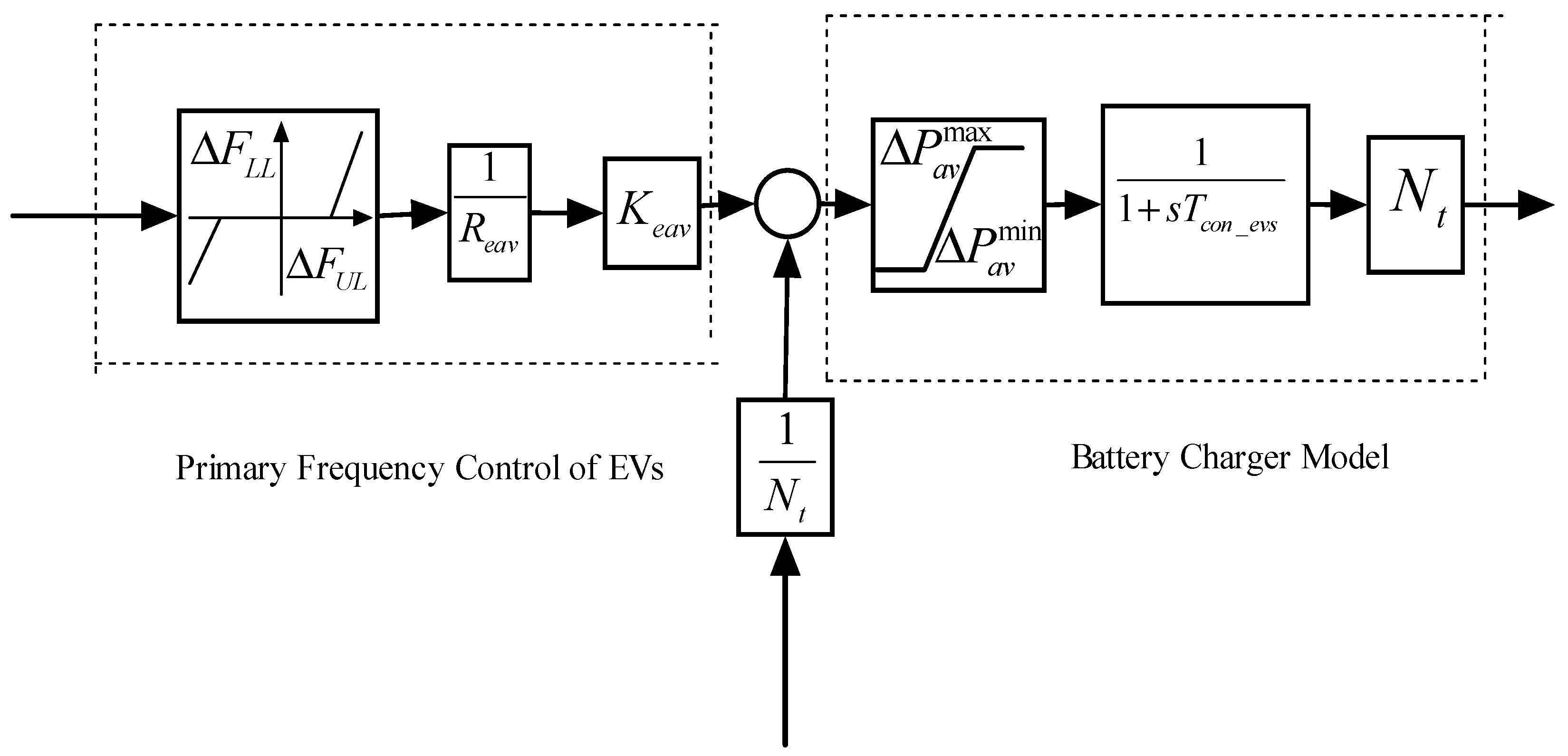
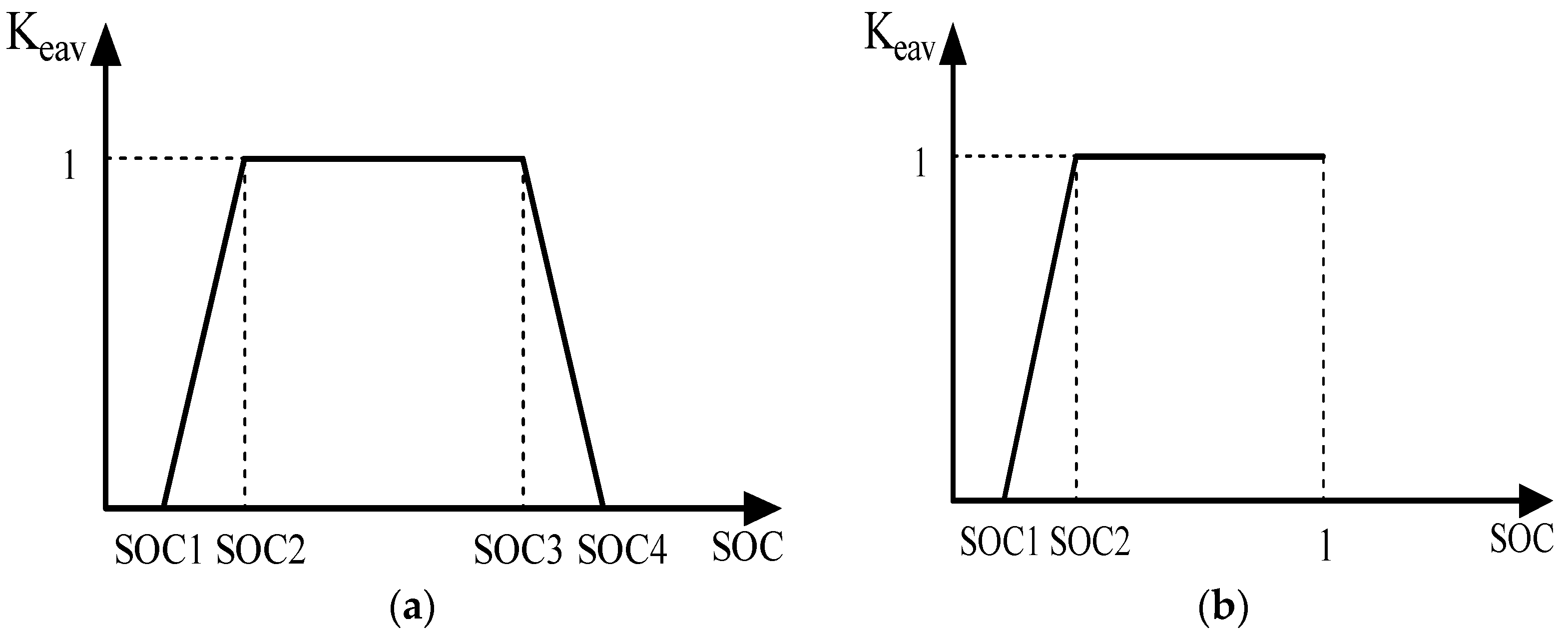
2.6. Electric Vehicle (EV)

In both areas, EVs are integrated to minimize mismatches during operation. Because of their enormous energy reserves, many aggregated EVs can help the LFC of PS [48]. Furthermore, plugged-in electric vehicles are considered energy storage devices and are used for frequency regulation in [49]. An aggregate model of EV fleet is presented in Figure 2, which includes the battery charger and the primary frequency control (PFC) for LFC. The power exchange between the vehicle battery and grid is controlled by battery charger. All EVs might suddenly detach from the MG, resulting in unwanted frequency regulation. Therefore, each EV has a dead band function (DBF) with droop characteristics [37]. The upper limit (∆FUL) and lower limit (∆FLL) of frequency deviation of DBF have been taken as 0.001 Hz and −0.001 Hz, respectively. The choice of upper and lower limits for the dead band function in an electric vehicle’s primary frequency control depends on various factors, including the accuracy of the sensors, the responsiveness of the control system, and the need for balanced frequency stabilization within the vehicle’s energy efficiency and lifespan. The value of the droop coefficient of the comprehensive model (Rag) is assumed to be the same as for conventional units, i.e., 2.4 Hz/p.u. MW. In Figure 2, Keav is the participation factor of EVs, and Tev is the time constant of EVs’ batteries. The value of Keav varies with the SOC of the EV. The changing and ideal state of charging (SOC) of the battery is presented in Figure 3. The proposed model is a single plugged-in electric vehicle (PEV) for the provision of PFC to an aggregate model of whole PEV fleets. In principle, the aggregate model of PEV fleets is the average model of the Nt number of PEVs, which is presented in Figure 2. Note that t denotes the hour of day. All the aggregate model parameters, such as Tcon_evs and Reav, can be simply determined, excluding the average participation factor of PEVs, i.e., Keav. A detailed derivation of PEVs is given in [50]. Keav is based on each PEV operating mode, and Keav is zero when PEVs detach from the grid. The share of PEVs in the charging mode and idle mode of all PEVs is presented in Figure 3 and is calculated from Equation (7).
K e a v S O C e a v = 0 1 α 1 k i 1 S O C + α c k i c S O C ϕ S O C e a v d S O C
where ϕ S O C e a v is the probability distribution function of the PEVs and the avarge value of battery state of charging SOCeav. Note that SOCeav depends on the size of the PEV battery. The upper and lower values of output power of EV fleet can be calculated as shown in Equations (8) and (9).
Δ P a g M a x = 1 N t Δ P e v
Δ P a g M i n = 1 N t Δ P e v
where Pev is the incremental change in generation in each area (p.u.), Pag is the output power of EVs, Nt is th total number of EVs connected in the EV fleet. In this study, 1000 discharged EVs are assumed in each area. The charging and discharging capacity of EV battery is considered in the range of ±5 kW and 50 kW for rapid start.

3. Controller Synthesis

This section explains the different control methods, objective function, and finally the modified dragonfly algorithm.

3.1. Controller Design

In order to eliminate frequency/tie-line power variations, the frequency regulator’s primary function is to balance power generation and load demand. An area control error signal is produced when step load disruption (SLD) is applied because it causes instant divergence in frequency and tie-line power flow. The frequency regulator adjusts the load reference set-point in response to the ACE signal to account for load changes, and it returns the system frequency and tie-line power flow to their nominal values. Three different control strategies have been evaluated and compared with this goal in mind.

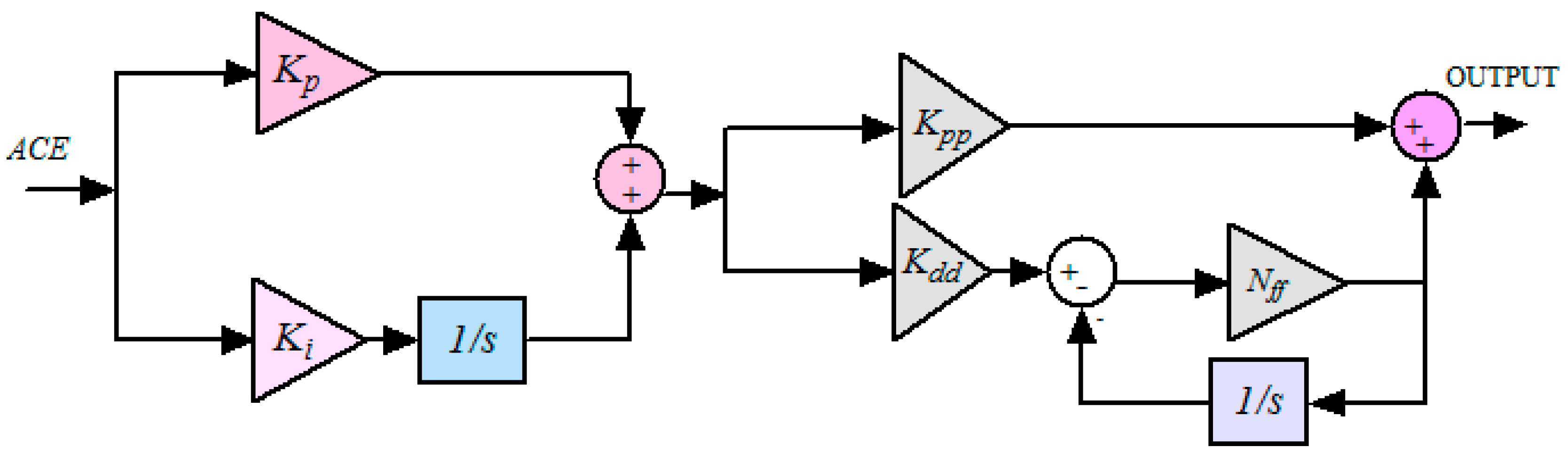
3.1.1. Control Method-1: PI-PDF Controller

Classical PIs and their other improved alternatives are noted for their simple strategy, cheap calculus burden, and simple implementation, leading to their common use in many PS [41,42,52]. Nevertheless, they have less ability to handle non-linearities, which makes them reasonably less effective to give the anticipated level of control presentation in big systems. However, in recent studies, to ameliorate the performance of conventional controllers, researchers have combined different conventional controllers and proposed multi/dual-stage controllers. With the same objective, in this current study, a dual-stage conventional PI-PDF controller is tested and compared with other control methods. The structure of the PI-PDF controller is presented in Figure 4.

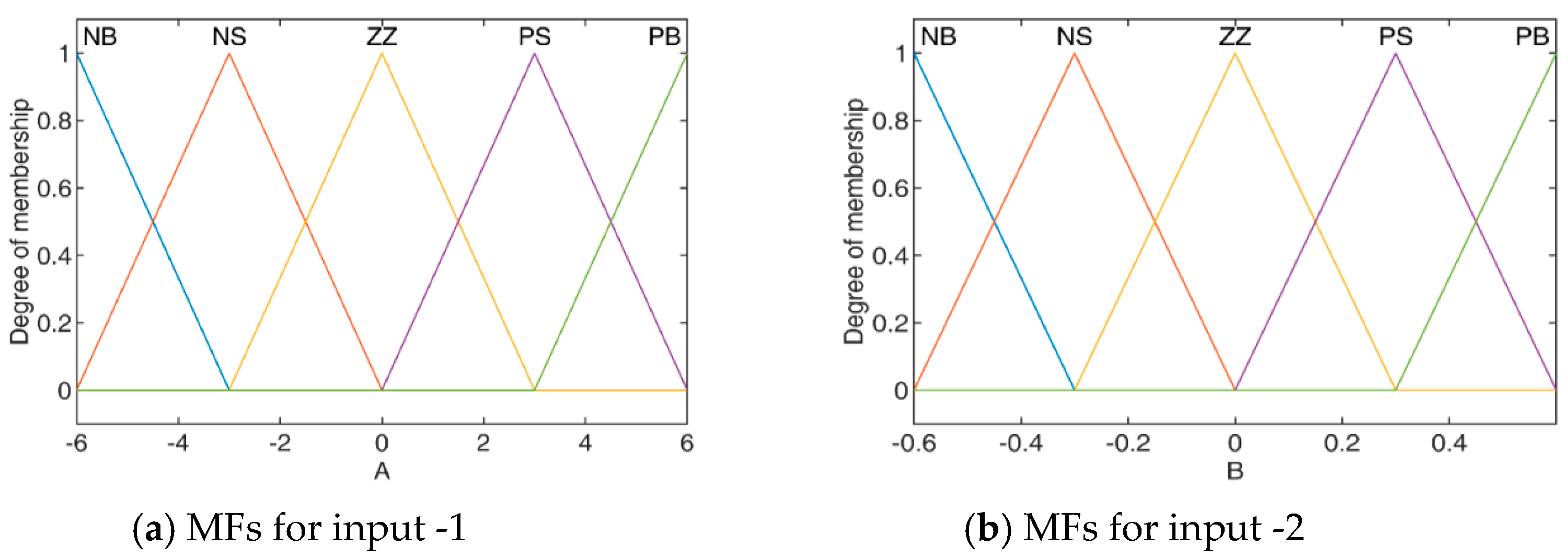
3.1.2. Control Method-2: FLC-PI-PDF Controller

To astound the limitations of classical controllers and to improve their performance, fuzzy logic has been assimilated into the controller [43,53], which will allow them to meet all control objectives for the proposed PS. Furthermore, fuzzy logic is used in cascaded controllers [26,54] to obtain better frequency regulation in the power system. An incremental performance has been achieved by these controllers, but they lead to complexity in designs as many parameters are needed for precise tuning. In addition, the responses they describe imply that they could yet be enhanced in terms of time-domain specifications. The presented work considered the FLC-PI-PDF controller and implemented it as an efficient and robust controller for the FR of the MG. The structure of the proposed controller for the MG model is shown in Figure 5.
Fuzzy logic is extensively used for control and several other applications ranging from academia to industry. Fuzzy logic control used in the literature is commonly used with two inputs and one output. The separate output with different ranges of membership functions were not determined for all gain factors in a cascaded controller. The designing of membership functions (MFs) for each input and output has an important role in the performance of FLC. MFs are the structure blocks of the fuzzy set model. Thus, the shapes of MFs are essential for a specific problem because they affect fuzzy estimation systems. They can have various shapes, such as triangular, Gaussian, trapezoidal, etc. An MF should fulfill only one condition, namely that it must vary between 0 and 1. However, the trial-and-error technique is generally used for the size of MF, as no precise method exists for selecting MFs. The size of the MF depends on how confident one is in a given linguistic variable. It depends more on intuition than on criteria. The function itself may be a random curve whose type we could specify as a function that works for us in terms of simplicity, speed, and convenience. As a result, improving model performance is not much influenced by MF type.
In the considered fuzzy set, five membership functions (MFs) are taken for each input and output signal. Basically, there is no prior knowledge on which MF is best suited for the problem. However, after a review of the extensive literature, triangular and gaussian MFs are more popular than other variants. Generally, the triangular MF is one of the most commonly used MF in practice. Gaussian MFs are popular methods for stipulating fuzzy sets because of their intuitive and concise notation. These curves have the benefit of being smooth and non-zero at each instant. In his paper, a triangular MF is taken within the limit and is adopted for the input and output of the FLC. Figure 6 and Figure 7 show the structure of MFs for two inputs and five outputs within their ranges, respectively. The different range for the inputs and outputs were estimated from the optimal gains of the PI-PDF controller. As presented in Figure 6 and Figure 7, the linguistic variables are defined as NB (negative big), NS (negative small), ZZ (zero), PS (positive small), or PB (positive big). Five MFs are considered for every input and output, hence 5 × 5 = 25 rules need to be set wisely for each output as given in Table 1. Here, if conditional declarations are presented that attempt to establish a link between the ACE and the derivative of the ACE with respect to time, Mamdani’s fuzzy inference method is used to simulate human decision making, and the center of gravity (centroid) method is used to generate crisp output during defuzzification from the output of the FLC.

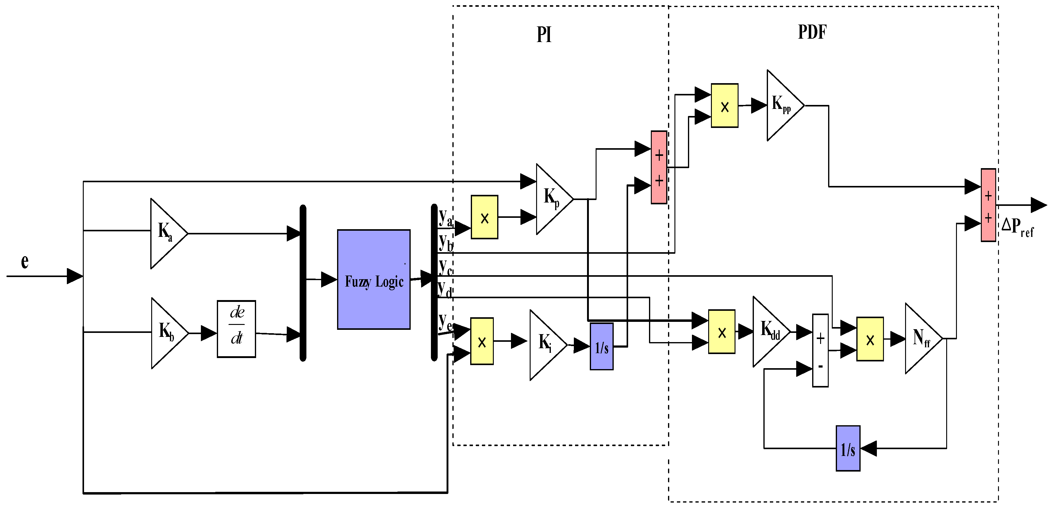
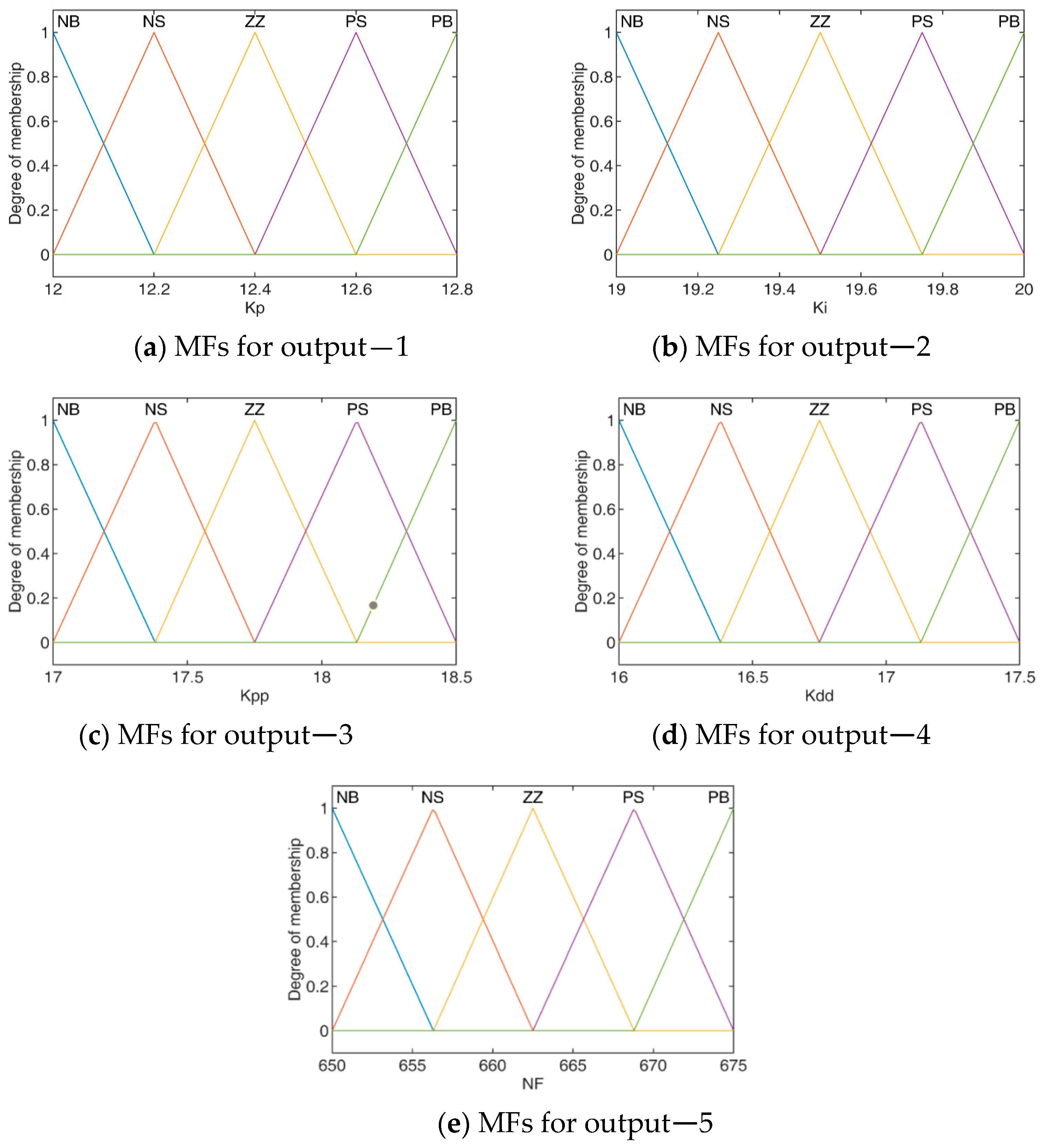
3.1.3. Control Method-3: FLC-SF-PI-PDF Controller

Furthermore, it can also be observed from the literature that the use of scaling factors (SFs) for the input and output of fuzzy controllers can solve the issue of the optimal design of membership functions. The scaling factor can help in adusting the output range, reducing rule complexity and minimizing the noise effect. Optimal values of SFs can be easily achieved with the help of optimization techniques which automatically provide the optimal adjustment of MF. Therefore, this study proposes an SF-based FLC-SF-PI-PDF controller as shown in Figure 8. To the best knowledge of the authors, the proposed control has not been implemented for FR of islanded MGs.
The PI controller acts as a primary controller and its output work as a set-point input for the secondary PDF controller. The F-M-PI-PDF controller takes ACE and ∆ACE as inputs after being weighted by Ka and Kb, producing the desired plant input ∆Pref as shown in Figure 8. ACE signals (e) are defined by Equation (10).
e = B Δ F i Δ P t i e
where B is the frequency bias, Δ F i is the change in frequency, and Δ P t i e is the change in tie-line power. If yi is the outputs of FLC, the broad control algorithm in terms of ACE to ∆Pref can be expressed as below in Equation (11):
Δ P r e f = e y a K p + e y b K i s e y c K p p + e y d K d d e y e N f f 1 + e y e N f f s
where y a ,   y b ,   y c ,   y d ,   y e are the output of the fuzzy set and K p , K i , K p p , K d d are the proportional, integral, derivative scaling factor gains, respectively, and N f f is the filter coefficient.

3.2. Objective Function

The goal of this study is to identify the decision variables’ ideal values for a controller that minimizes frequency deviation. In integral square error (ISE), the initial values of the error are given more weight than the suffix variables.
The ISE error function removes high error values faster, but it tolerates smaller error values and retains them for longer periods. The obtained responses are fast, although there is a low value for amplitude and oscillation. The obtained characteristics of ISE have prompted the authors to select objective works. After a fair comparison of the trapped error functions, it was analyzed that the ISE error function is better than the other objective functions [54,55]. The assumed objective function is presented below in Equation (12).
I S E K X ,   u   = 0 t s i m ( Δ F 1 2 + Δ F 2 2 + Δ P T i e 2   ) d t
where X represents the state variable (Ka, Kb, Kp, Ki, Kpp, Kdd, Nff), u is the control variable   u = u 2 u 3 , and t s i m is the simulation run time. Δ F 1 and Δ F 2 are the frequency deviation of area 1 and area 2, respectively. Δ P t i e is the power deviation in tie-line power. The parameters that are to be tuned for the proposed controller are represented in Equation (13) and the upper and lower limits of the scaling factor are tabulated below in Table 2.
K a m i n K a   K a m a x , K b m i n K b   K b m a x , K p m i n K p   K p m a x , K i m i n K i   K i m a x , K P P m i n K P P   K P P m a x , K d d m i n K d d   K d d m a x , N f f m i n N f f   N f f m a x

3.3. Modified Dragonfly Optimization

The dragonfly algorithm (DA), proposed in 2015 by S. Mirjalili [56], is a nature-inspired, swarm-based, meta-heuristic optimization technique that mimics the hunting and migration behaviors of insect dragonflies. This algorithm was further modified by overcoming its observed limitations in 2021 as a modified dragonfly algorithm (MDA) [57]. This correction made the DA more suitable for solving real-life engineering problems.
This insect algorithm pursues three basic principles:
(i)
Seperation operator (Sq): this operator prevents the collision of the dragonfly with others flying in the vicinity.
(ii)
Aligment operator (Aq): this operator helps to match the flying speed of the dragonfly with other flies.
(iii)
Cohesion operator (Cq): this operator atttracts the individual dragonfly towards the center of the group.
Furthermore, dragonfly has an attraction operator (Fq) that attracts them towards the food source and a distract operator (Eq) that keep them away from the enemy. The characteristics of the dragonfly are considered, as well as the amalgamation of above five corrective patterns, as mentioned above. Furthermore, MDA operates on two vectors: the first is the position vector (X) and the second is (∆X), which is similar to velocity vector of PSO.
The pseudo-code for the MDA is presented in Algorithm 1.
Algorithm 1. Pseudo-code of modified dragonfly optimization algorithm.
1.Initialize  the   feasible   algorithm   parameters   i . e . ,   iteration i m a x ,   population   size ,   constraints   ( C 1   , C 2 , .   , C 5 ), and intial weight (w lies between 0.2–0.9).
( C 1   , C 2 = 0.1 )   ( C 3 = 0.7 , C 4 , C 5 = 1 )
2.Initiate the step vector Δ X i t r + 1 = ( C 1 S q +   C 2 A q + C 3 C q   + C 4 F q  +   C 5 E q ) + w Δ X i t r .   X i t r + 1 = X i t r + Δ X i t r + 1
3.for i = 1 :   i m a x  do
4.Determine each dragonfly’s fitness with reference to its position.
5.Update the food source and enemy location with respect to the dragonflies.
6.Determine   the   value   of   A p ,   C p ,   S p ,   F p ,   and   E p from
S q = q N o . x x q ;     A q = q = 1 N o . v q N 0 ;   C q = q = 1 N o . x q N 0 x
 Here, x is the individual current position, while x q and v q are the qth position and speed of neighboring individual, respectively. N0 is the number of dragonflies in the group
A t t r a c t i o n   ( F p ) = x + x    and     D i s t r a c t i o n   ( E p ) = x + x
 ( x +   a n d   x ) are the location of nearby food and enemy.
7.Upgrade the neighboring diameter of a dragonfly.
8.If an individual has at least one dragonfly in their vicinity, then
9.Upgrade the velocity vector as
x i t r + 1 = x i t r + x i t r + 1 . r a n d
 rand is a random number between (0 to 1)
And
Update the position vector as
x i t r + 1 = x i t r + Y . L e v y d ; Y = S m a x i t r 2
Levy is a standard levy flight function.
10.Otherwise,
Upgrade   the   position   vector   as   x i t r + 1 = x i t r + Y . L e v y d ; Y = S m a x i t r 2
11.End if
12.Determine the insect fitness as per the newly updated position while considering its limitation.
13.End for
14.Preserve the best obtain solutions

4. Results

In this paper, the MG model as presented in Figure 1 was simulated in Matlab with the purpose of observing the performance of the proposed control scheme. The frequency response of the proposed system has been studied, assuming the simulation time (tsim) to be 100 s. MDA is used to tune the gains of the MDA: PI-PDF and MDA: FLC-SF-PI-PDF controller by setting fixed limits of lb and ub. The error K is computed with a population size of 20 for 100 iterations and 20 runs. The MG includes renewable energy sources, such as ORC-based solar thermal power system (STPS) and wind power, which are heavily dependent on environmental conditions. The RFB and CES have also been incorporated to improve the steady-state stability of the system. Furthermore, EVs are integrated with the proposed MG to ameliorate the LFC. Different case studies have been performed considering different conditions of RESs and load variations to present the efficacy of the proposed approach.

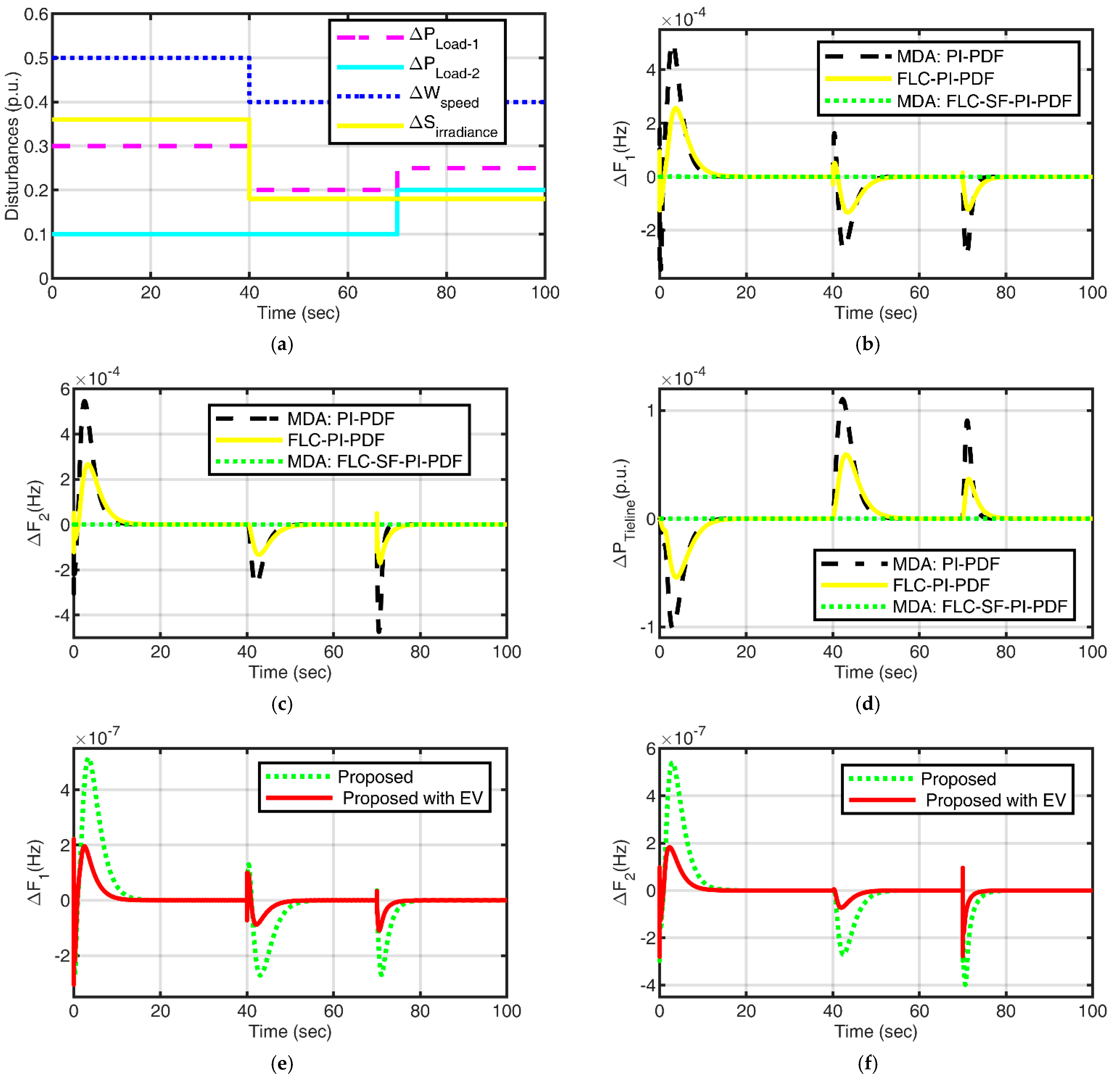
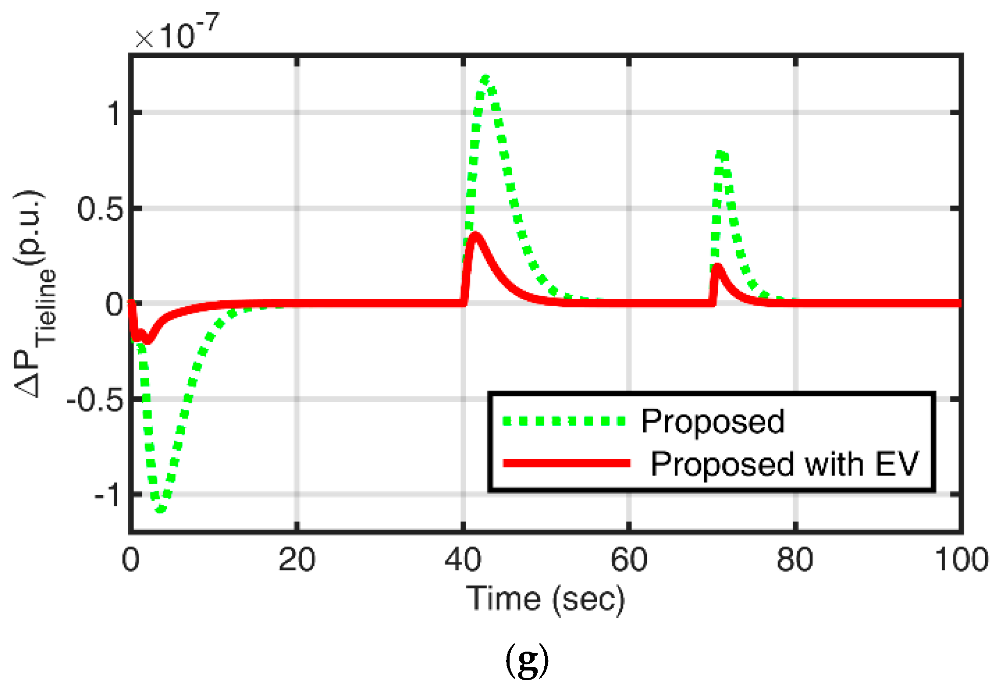
4.1. Case 1: Step Variations

In this case, step variations are considered for load, wind speed, and solar irradiance as presented in Figure 9a and Equations (14)–(16) in the proposed MG. Performance analysis of the controllers, i.e., MDA: PI-PDF, FLC-PI-PDF, MDA: FLC-SF-PI-PDF, and MDA: FLC-SF-PI-PDF with EV was conducted based on the performance indices (Us, Os, IAE, ISE, ITAE, ITSE).
P L o a d 1 = 0.3   p u   t 40 s 0.2   p u   40 s t 70 s 0.25   p u   t 70 s ,   P L o a d 2 = 0.1 p u   t 70 s 0.2 p u   t 70 s
P w i n d = 0.5 p u   t 40 s 0.4 p u   t 40 s
P s o l a r = 0.35 p u   t 40 s 0.15 p u   t 40 s
The obtained frequency and tie-line power responses with MDA: PI-PDF, FLC-PI-PDF, and MDA: FLC-SF-PI-PDF controllers are presented in Figure 9b–d. Furthermore, to attain the minimum integral square error, MDA is proposed. MDA provides the optimal value of the scaling factor of the proposed controller. The optimal values of the scaling factors are as follows: Kp = 14.17, Ki = 24.99, Kpp = 24.96, Kdd = 18.14, Nff = 558.19; and Ka = 1.25, Kb = 1.45, Kp = 21.80, Ki = 17.38, Kpp = 24.13, Kdd = 24.13, Nff = 538.54 for MDA: PI-PDF and MDA: FLC-SF-PI-PIDF controllers, respectively. The frequency and tie-line response with the MDA-tuned fuzzy-modified PI-PDF controller with and without EVs are presented in Figure 9e–g. It is clearly depicted that the suggested MDA-tuned modified fuzzy-based PI-PDF controller has the best performance compared to the fuzzy-based PI-PDF controller. Furthermore, the integration of EVs into the MG and the response of frequency and tie-line power are improved. The comparative analysis of performance indices is presented in Table 3 for the applied disturbances.
From Table 3 and Figure 9b–g (for applied disturbances), it can be observed that performance indices value Us (F1_US (−3.0741 × 10⁻⁷ Hz), F2_US (5.1543 × 10⁻⁷ Hz), Ptie_US (1.9323 × 10⁻⁷ puMW), Os (F1_OS (1.0235 × 10⁻⁶ Hz), F2_OS (4.4396 × 10⁻⁷ Hz), Ptie_OS (1.0797 × 10⁻⁷ puMW), IAE (1.0738 × 10⁻⁵), ISE (2.7032 × 10⁻¹²), ITAE (2.9012 × 10⁻⁴), and ITSE (5.2113 × 10⁻¹¹) with the MDA: fuzzy-SF-PI-PDF controller are lower compared to that of the fuzzy-PI-PDF controller. Furthermore, it is noted that after integration of EVs, performance indices are minimized and the values are as follows: Us (F1_US (−3.0517 × 10⁻⁷ Hz); F2_US (2.2129 × 10⁻⁷ Hz); Ptie_US (2.8031 × 10⁻⁷ puMW)); Os (F1_OS (2.2129 × 10⁻⁷ Hz); F2_OS (1.8254 × 10⁻⁷ Hz); Ptie_OS (3.565 × 10⁻⁸ puMW); IAE (3.0154 × 10⁻⁶); ISE (2.8188 × 10⁻¹³); ITAE (7.4676 × 10⁻⁵); and ITSE (4.6227 × 10⁻¹²). The power contributions of the wind turbine, ORC, BDG, RFB, CES, and EVs for area 1 and area 2 are depicted in Figure 10a and Figure 10b, respectively.
As shown in Figure 10a,b, initially area 1 and area 2 are subjected to a 30% and 10% load disturbance, respectively. To compensate for the increased load demand, BDG, RFB, and EV units of area 1 deliver required power to the MG to fulfill the required demand. Afterwards, wind power generation is enough to fulfill the power demand and to charge the EVs during access generation. In area 2, initially the BDG and CES provide the required power against the demanded power. Afterwards, ORC solar power generation is enough to fulfill load demand and to recharge EVs and CES during access generation. The BDG operates when enough power is not supplied by the renewable sources and the energy storing devices of the microgrid. Therefore, the proposed control strategy provides better frequency regulation and energy management in the microgrid.

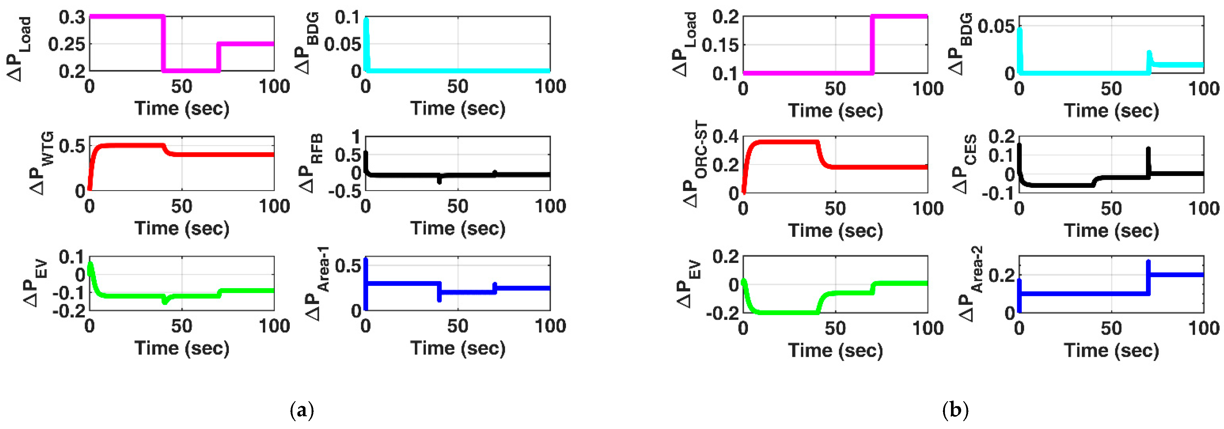
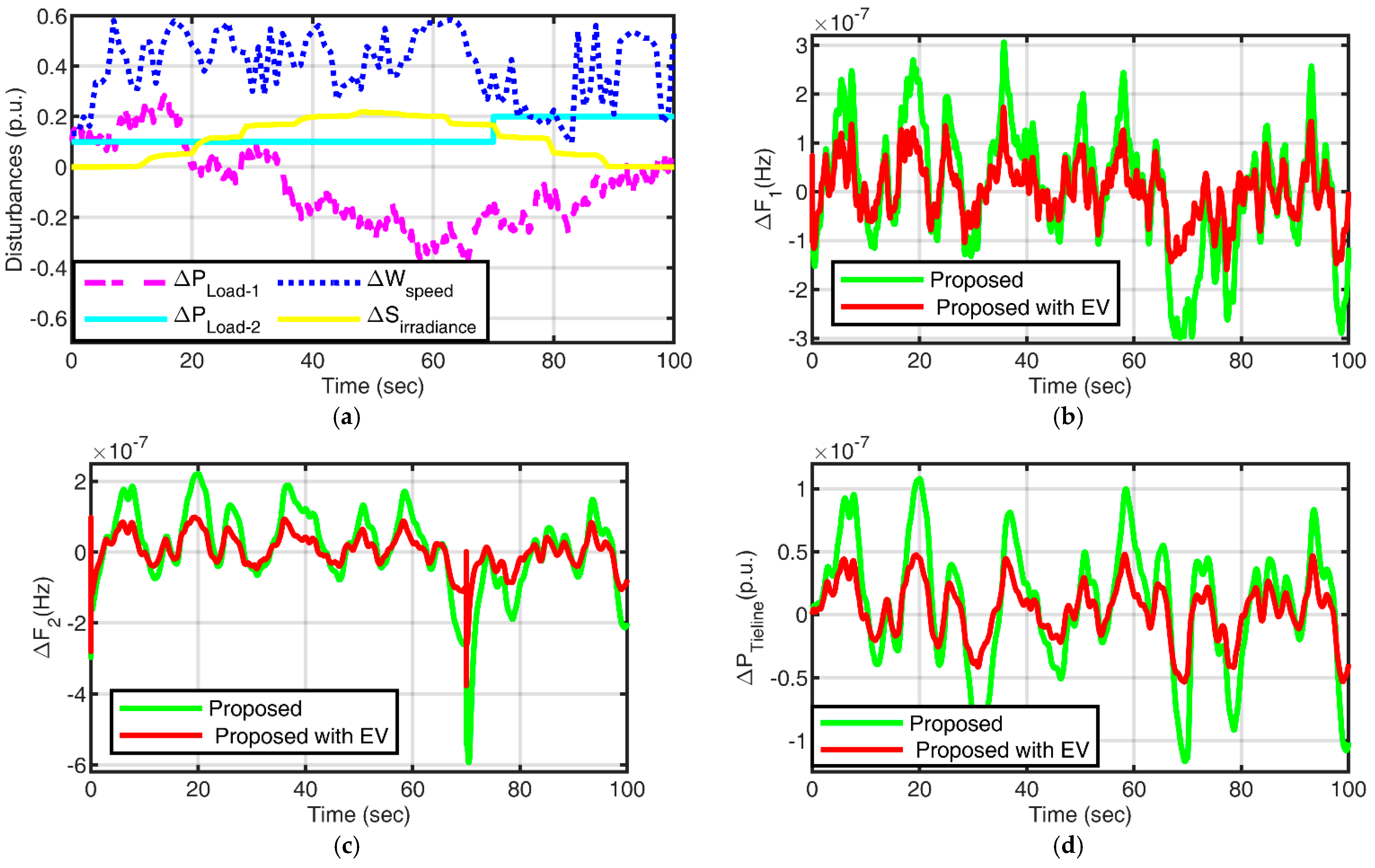
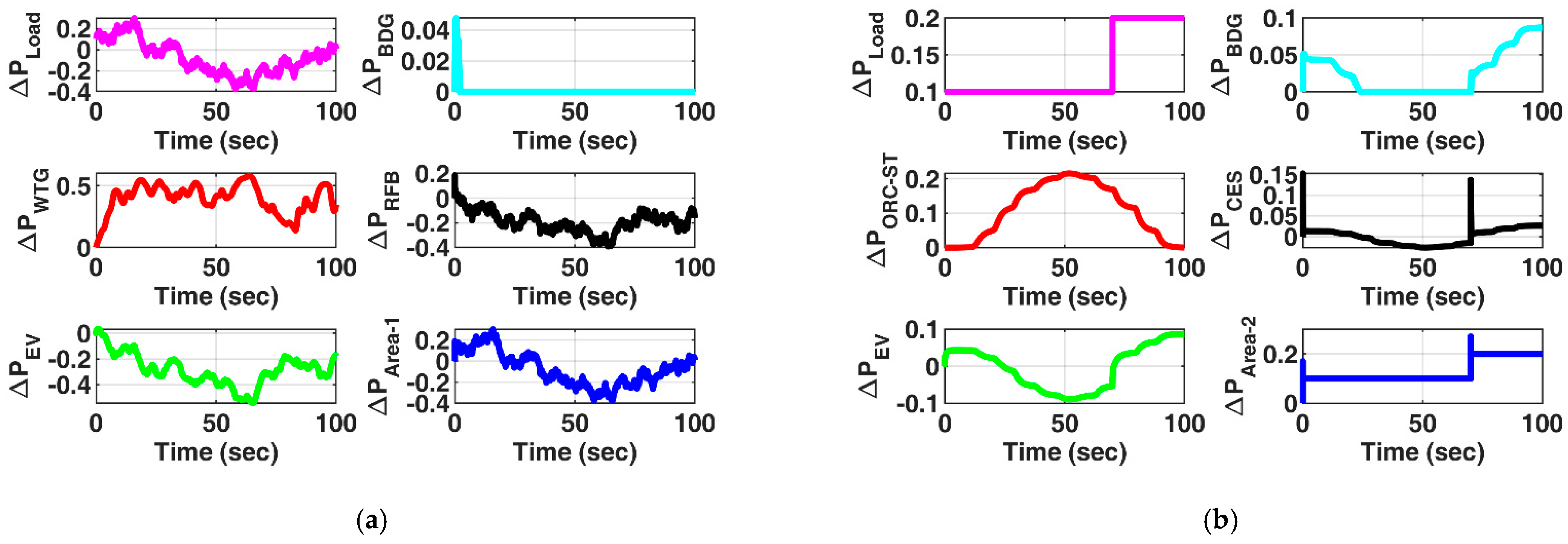
4.2. Case 2: Random Variation

In this case, to analyze the real operation of the MG, the random variations for load in area 1, wind speed, and solar irradiance are considered as presented in Figure 11a. The obtained frequency and tie-line power responses with the proposed controller are presented in Figure 11b–d. The performance indices of proposed strategies are tabulated in Table 4.
It is clearly depicted in Figure 11b–d that after the integration of EVs in the MG, the system performance is enhanced in terms of less variation in frequency and tie-line power. It is clearly depicted in Table 4 that after the integration of EVs, performance indices are minimized and the values are Us (F1_US (−1.5938 × 10⁻⁷ Hz), F2_US (−3.7614 × 10⁻⁷ Hz), Ptie_US (−5.3433 × 10⁻⁸ puMW)), Os (F1_OS (1.7292 × 10⁻⁷ Hz), F2_OS (9.8764 × 10⁻⁸ Hz), Ptie_OS (4.7799 × 10⁻⁸ puMW)), IAE (1.053 × 10⁻⁵), ISE (6.6924 × 10⁻¹³), ITAE (0.00052272), and ITSE (3.4506 × 10⁻¹¹). To balance the power generation and power demand for applied load variations, the participation of wind turbine, ORC, BDG, RFB, CES, and EVs for area 1 and area 2 is depicted in Figure 12a and Figure 12b, respectively.
As shown in Figure 12a,b, area 1 and area 2 are subjected to random and step load variations, respectively. It is clearly depicted in Figure 12 that the maximum power is supplied by the wind unit in area 1. EVs and RFB units are charged from the access power generated by the wind unit. The BDG supplies power only for the instant in which the wind unit is generating less power. Furthermore, in area 2, step load of 0.2 pu is applied at 70 s and demand power is delivered by the solar unit when solar irradiance is available to generate solar power. EVs and CES units are charged during access generation from solar power and supply the power when demand is increased and solar generation is less. The BDG delivers power only when storage units and renewables sources are unable to supply the demand power.

4.3. Sensitivity Analysis

Robustness analysis of the proposed controller with EVs is performed by considering the physical constraints and parametric uncertainties under disturbances shown in Figure 11a.

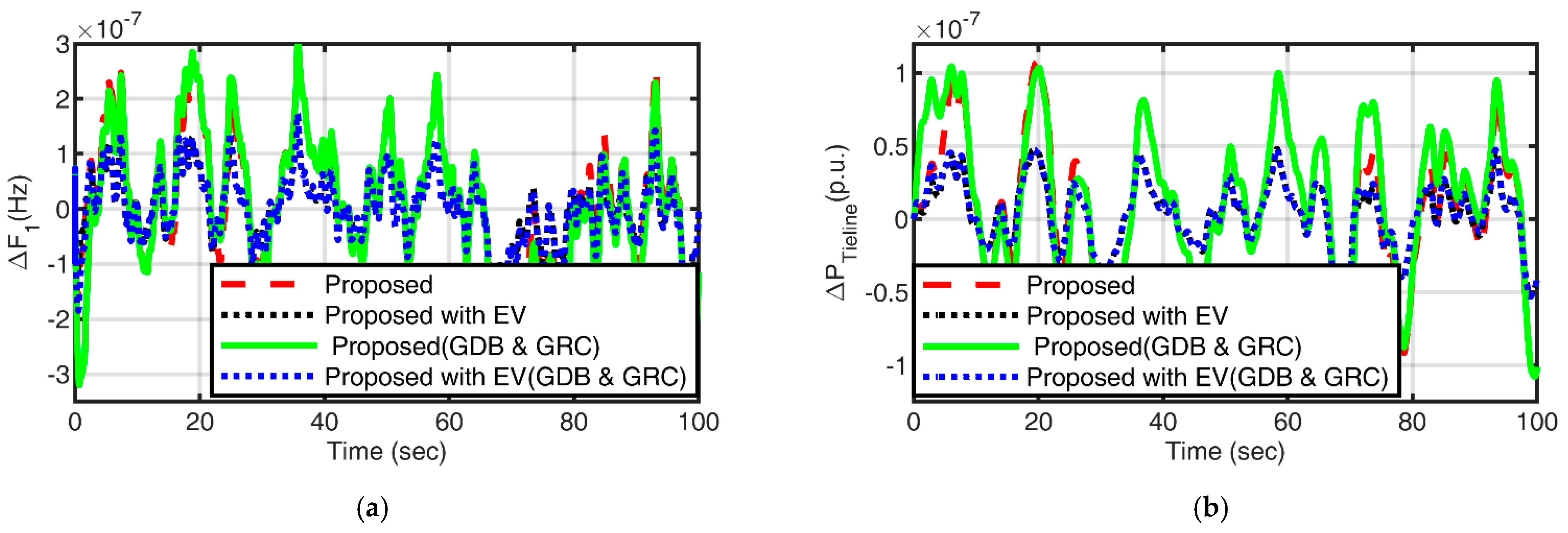
4.3.1. Physical Constraints

In non-linear power systems, the power generated can only vary due to a specified peak rate and refers to mechanical and thermal action constraints as generation rate constraints (GRCs). While the speed governor dead band (GDB) provides position to the governor control valve during operation, the turbine speed may increase or decrease before the valve changes position. The GDB has the ability to partially affect system response. Therefore, the performance of the proposed control approach has been studied considering the GRC (0.0017 pu/s) and GDB effect in biodiesel units. Figure 13a,b displays the dynamic response of the frequency deviation and the tie-line power deviation. From Figure 13, it is clear that even with the GDB and GRC present, the dynamic responses of the system are totally acceptable and within IEEE standard tolerances.

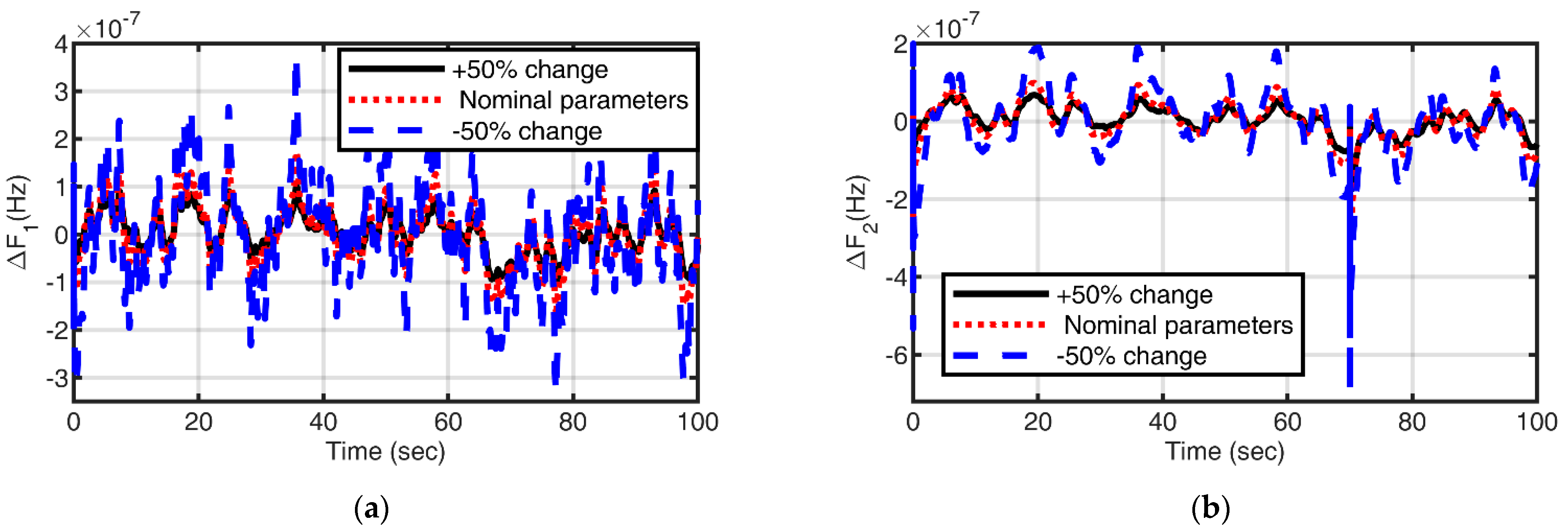
4.3.2. MG Parameter Variations

The parameters of the study system have been varied within a range of ±50% without changing the optimal values of controller gain. Figure 14a,b presents the frequency responses. It can be easily seen in Figure 14 that the settling time and peak overshoot/undershoot values change entirely under the permissible limit of IEEE standards within acceptable limits and are comparable with the respective values obtained within the nominal system parameters. It can therefore be concluded that the proposed control approach has effectively provided a strong and stable control.

4.4. Stability Analysis

The eigenvalues analysis method is deployed to observe the stability of the system. Eigenvalues are investigated to obtain information on stability within the proposed approaches, i.e., FLC-PI-PDF, MDO: FLC-SF-PI-PDF, and MDO: FLC-SF-PI-PDF with EVs. The computed eigenvalues are shown in Table 5 along with their results. Table 5 shows that all of the eigenvalues have negative real portions, demonstrating the stability of the system with the necessary stability margins. The imaginary portion of the eigenvalues, which have a relatively small size, demonstrates the system response’s quick decay. As a result, the study that was conducted shows that the recommended control strategy has increased the system’s stability.

5. Conclusions

The article proposed an MDA-tuned FLC-SF-PI-PDF controller-based frequency control strategy to maintain the reliable operation of the two-area islanded microgrid. An FLC-SF-PI-PDF controller is designed to stabilize system frequency and balance load demand. In addition, the performance of the proposed MG is tested to analyze the effect of EV integration in both areas. The effectiveness of the proposed control strategy has been evaluated by considering different performance indices. Different case studies are performed to analyze the performance of the proposed approach, including sensitivity analysis. Stability analysis has been performed using eigenvalues. The major findings of the study are as follows:
  • The obtained results indicate that tuning the scaling factors using the modified dragonfly algorithm has a great impact on the performance of the fuzzy controller.
  • The FLC-SF-PI-PDF controller tuned with MDA is the most suitable controller for the proposed two-area island microgrid.
  • It is observed from different case studies that after the integration of EVs into MGs, the system performance improves significantly.
  • After the integration of EVs, the percentage advancement in the performance indices of 71.2% (IAE), 74.13% (ITAE), 89.6% (ISE), and 91.2% (ITSE) for case 1 and 54.32% (IAE), 55.79% (ITAE), 63.73% (ISE), and 79.59% (ITSE) for case 2 are observed.
  • The proposed LFC scheme also demonstrates robust performance under variable operating and loading conditions, system parametric uncertainties, and various non-linearities of the system.
  • Eigenvalue analysis confirms the stability of the microgrid system working under the proposed LFC strategy.
The results obtained under various case studies are impressive and support the proposed LFC scheme. In the future, the performance of the proposed controller can be investigated for the integration of other EES devices. The immediate extension of this work is to cogitate real-time analysis using a real-time simulator for experimental verification of the proposed work.

Author Contributions

B.S.: Conceptualization, Software, Validation, Investigation, Visualization, Writing—original draft; M.S.: Structuring the draft, Visualization, Writing and editing; A.S.: Reviewing, Formal analysis, and Supervision; S.K.B.: Methodology, Supervision, Proof-Reading and Reviewing. All authors have read and agreed to the published version of the manuscript.

Funding

This research received no external funding.

Institutional Review Board Statement

Not applicable.

Informed Consent Statement

Not applicable.

Data Availability Statement

Not applicable.

Conflicts of Interest

The authors have no conflict of interest to declare.

Abbreviations

KVA valve gain of biodiesel generator (1)
TVA valve actuator delay (0.05 s)
KBEEngine gain of biodiesel generator (1)
KWTGWind turbine gain constant (1)
TWTGWind turbine time constant (1.5)
KCESCapacitor gain (0.03)
TCESCapacitor time constant (0.0352 s)
KstGain of ORC solar turbine (1)
TstTime constant of ORC solar turbine (1.8 s)
KTGain of ORC solar generator (1)
TTORC solar power plant time constant (0.3)
KRFBGain constant of redox flow battery (0.67)
TRFBTime constant of redox flow battery (0.01 s)
BFrequency bias factor (0.510)
DDamping factor (0.02)
MInertial constant of the system (0.012)
RDroop constant (2.4 Hz/puMW)
T12Synchronizing torque coefficient of two areas (0.08)
ReavEV droop constant (2.4 Hz/puMW)
KeavGain of EV (1)
Tcon_evsTime constant of EV (1 s)
NtTotal number of EVs
∆fChange in frequency
∆PtieChange in tie-line power
Us; OsSetting time, under shoot, over shoot
IAEIntegral absolute error
ITAEIntegral time absolute error
ISEIntegral square error
ITSEIntegral time square error
ACEArea control error

References

  1. Sarkar, T.; Bhattacharjee, A.; Samanta, H.; Bhattacharya, K.; Saha, H. Optimal design and implementation of solar PV-wind-biogas-VRFB storage integrated smart hybrid microgrid for ensuring zero loss of power supply probability. Energy Convers. Manag. 2019, 191, 102–118. [Google Scholar] [CrossRef]
  2. Nayak, P.C.; Prusty, U.C.; Prusty, R.C.; Panda, S. Imperialist competitive algorithm optimized cascade controller for load frequency control of multi-microgrid system. Energy Sources Part A Recover. Util. Environ. Eff. 2021, 00, 1–23. [Google Scholar] [CrossRef]
  3. Semshchikov, E.; Hamilton, J.; Wu, L.; Negnevitsky, M.; Wang, X.; Lyden, S. Frequency control within high renewable penetration hybrid systems adopting low load diesel methodologies. Energy Procedia 2019, 160, 483–490. [Google Scholar] [CrossRef]
  4. Rai, A.; Das, D.K. The development of a fuzzy tilt integral derivative controller based on the sailfish optimizer to solve load frequency control in a microgrid, incorporating energy storage systems. J. Energy Storage 2022, 48, 103887. [Google Scholar] [CrossRef]
  5. Sarkhanloo, M.S.; Bevrani, H.; Mirzaei, R. Environmental Effects A comprehensive coordinated frequency control scheme for double- fed induction generator wind turbine, battery, and diesel generators in islanded microgrids. Energy Sources Part A Recover. Util. Environ. Eff. 2021, 2021, 1–23. [Google Scholar]
  6. Dutta, A.; Prakash, S. Load frequency control of multi-area hybrid power system integrated with renewable energy sources utilizing FACTS & energy storage system. Environ. Prog. Sustain. Energy 2020, 39, 1–13. [Google Scholar]
  7. Rahman, A.; Saikia, L.C.; Sinha, N. Automatic generation control of an interconnected two-area hybrid thermal system considering dish-stirling solar thermal and wind turbine system. Renew. Energy 2017, 105, 41–54. [Google Scholar] [CrossRef]
  8. Singh, P.; Meena, N.K.; Slowik, A.; Bishnoi, S.K. Modified African Buffalo Optimization for Strategic Integration of Battery Energy Storage in Distribution Networks. IEEE Access 2020, 8, 14289–14301. [Google Scholar] [CrossRef]
  9. Sharma, M.; Bansal, R.K.; Prakash, S.; Dhundhara, S. Frequency Regulation in PV integrated Power System using MFO tuned PIDF controller. In Proceedings of the 2018 IEEE 8th Power India International Conference (PIICON), Kurukshetra, India, 10–12 December 2018; pp. 1–6. [Google Scholar]
  10. Sahu, R.K.; Gorripotu, T.S.; Panda, S. Automatic generation control of multi-area power systems with diverse energy sources using Teaching Learning Based Optimization algorithm. Eng. Sci. Technol. Int. J. 2016, 19, 113–134. [Google Scholar] [CrossRef] [Green Version]
  11. Satapathy, P.; Debnath, M.K.; Singh, M.B.; Mohanty, P.K. Design of FPI controller for load frequency control of a nonlinear power system. In Proceedings of the 2018 Technologies for Smart-City Energy Security and Power (ICSESP), Bhubaneswar, India, 28–30 March 2018; Volume 2018-Janua, pp. 1–6. [Google Scholar]
  12. Mohanty, B. TLBO optimized sliding mode controller for multi-area multi-source nonlinear interconnected AGC system Electrical Power and Energy Systems TLBO optimized sliding mode controller for multi-area multi-source nonlinear interconnected AGC system. Int. J. Electr. Power Energy Syst. 2019, 73, 872–881. [Google Scholar] [CrossRef]
  13. Shiva, C.K.; Mukherjee, V. A novel quasi-oppositional harmony search algorithm for AGC optimization of three-area multi-unit power system after deregulation. Eng. Sci. Technol. Int. J. 2016, 19, 395–420. [Google Scholar] [CrossRef] [Green Version]
  14. Kumar, N.; Tyagi, B.; Kumar, V. Deregulated Multiarea AGC Scheme Using BBBC-FOPID Controller. Arab. J. Sci. Eng. 2017, 42, 2641–2649. [Google Scholar] [CrossRef]
  15. Sharma, M.; Prakash, S.; Saxena, S.; Dhundhara, S. Optimal Fractional-Order Tilted-Integral-Derivative Controller for Frequency Stabilization in Hybrid Power System Using Salp Swarm Algorithm. Electr. Power Compon. Syst. 2021, 48, 1912–1931. [Google Scholar] [CrossRef]
  16. Latif, A.; Hussain, S.M.S.; Das, D.C.; Ustun, T.S. Double stage controller optimization for load frequency stabilization in hybrid wind-ocean wave energy based maritime microgrid system. Appl. Energy 2021, 282, 116171. [Google Scholar] [CrossRef]
  17. El-Fergany, A.A.; El-Hameed, M.A. Efficient frequency controllers for autonomous two-area hybrid microgrid system using social-spider optimiser. IET Gener. Transm. Distrib. 2017, 11, 637–648. [Google Scholar] [CrossRef]
  18. Singh, B.; Slowik, A.; Bishnoi, S.K. A Dual-Stage Controller for Frequency Regulation in a Two-Area Realistic Diverse Hybrid Power System Using Bull–Lion Optimization. Energies 2022, 15, 8063. [Google Scholar] [CrossRef]
  19. Cam, E.; Gorel, G.; Mamur, H. Use of the Genetic Algorithm-Based Fuzzy Logic Controller for Load-Frequency Control in a Two Area Interconnected Power System. Appl. Sci. 2017, 7, 308. [Google Scholar] [CrossRef] [Green Version]
  20. Nanda, J.; Mangla, A. Automatic Generation Control of an Interconnected and Fuzzy Logic Controller. In Proceedings of the 2004 IEEE International Conference on Electric Utility Deregulation, Restructuring and Power Technologies, Hong Kong, China, 5–8 April 2004; pp. 372–377. [Google Scholar]
  21. Mohammadikia, R.; Aliasghary, M. A fractional order fuzzy PID for load frequency control of four-area interconnected power system using biogeography-based optimization. Int. Trans. Electr. Energy Syst. 2019, 29, e2735. [Google Scholar] [CrossRef]
  22. Yakout, A.H.; Attia, M.A.; Kotb, H. Marine Predator Algorithm based Cascaded PIDA Load Frequency Controller for Electric Power Systems with Wave Energy Conversion Systems. Alex. Eng. J. 2021, 60, 4213–4222. [Google Scholar] [CrossRef]
  23. Choudhary, A.K.; Prakash, S.; Sharma, M.; Dhundhara, S. Grasshopper optimisation based robust power/frequency regulator for shipboard. IET Renew. Power Gener. 2020, 14, 3568–3577. [Google Scholar] [CrossRef]
  24. Singh, A.; Suhag, S. Frequency regulation in an AC microgrid interconnected with thermal system employing multiverse-optimised fractional order-PID controller. Int. J. Sustain. Energy 2020, 39, 250–262. [Google Scholar] [CrossRef]
  25. Khooban, M.H.; Niknam, T. A new intelligent online fuzzy tuning approach for multi-area load frequency control: Self Adaptive Modified Bat Algorithm. Int. J. Electr. Power Energy Syst. 2015, 71, 254–261. [Google Scholar] [CrossRef]
  26. Aryan, P.; Raja, G.L. Design and Analysis of Novel QOEO Optimized Parallel Fuzzy FOPI-PIDN Controller for Restructured AGC with HVDC and PEV. Iran. J. Sci. Technol. Trans. Electr. Eng. 2022, 46, 565–587. [Google Scholar] [CrossRef]
  27. Esmaeili, M.; Shayeghi, H.; Nooshyar, M.; Aryanpour, H. Design of new controller for load frequency control of isolated microgrid considering system uncertainties. Int. J. Power Energy Convers. 2018, 9, 285. [Google Scholar] [CrossRef]
  28. Khooban, M.H.; Niknam, T.; Shasadeghi, M.; Dragicevic, T.; Blaabjerg, F. Load Frequency Control in Microgrids Based on a Stochastic Noninteger Controller. IEEE Trans. Sustain. Energy 2018, 9, 853–861. [Google Scholar] [CrossRef]
  29. Elsisi, M.; Bazmohammadi, N.; Guerrero, J.M.; Ebrahim, M.A. Energy management of controllable loads in multi-area power systems with wind power penetration based on new supervisor fuzzy nonlinear sliding mode control. Energy 2021, 221, 119867. [Google Scholar] [CrossRef]
  30. Kocaarslan, I.; Çam, E. Fuzzy logic controller in interconnected electrical power systems for load-frequency control. Int. J. Electr. Power Energy Syst. 2005, 27, 542–549. [Google Scholar] [CrossRef]
  31. Arya, Y. Automatic generation control of two-area electrical power systems via optimal fuzzy classical controller. J. Frankl. Inst. 2018, 355, 2662–2688. [Google Scholar] [CrossRef]
  32. Tripathy, D.; Behera, S.; Choudhury, N.B.D. Implementation of Grasshopper optimization algorithm based cascaded fuzzy PD-PI controller for frequency stability in a multi-area power system. J. Interdiscip. Math. 2020, 23, 335–345. [Google Scholar] [CrossRef]
  33. Çelik, E.; Öztürk, N. Novel fuzzy 1PD-TI controller for AGC of interconnected electric power systems with renewable power generation and energy storage devices. Eng. Sci. Technol. Int. J. 2022, 35, 101166. [Google Scholar] [CrossRef]
  34. Annapoorani, K.I.; Rajaguru, V.; Padmanabhan, S.A.; Kumar, K.M.; Venkatachalam, S. Fuzzy logic-based integral controller for load frequency control in an isolated micro-grid with superconducting magnetic energy storage unit. Mater. Today Proc. 2022, 58, 244–250. [Google Scholar] [CrossRef]
  35. Aftab, M.A.; Hussain, S.M.S.; Latif, A.; Das, D.C.; Ustun, T.S. IEC 61850 communication based dual stage load frequency controller for isolated hybrid microgrid. Int. J. Electr. Power Energy Syst. 2021, 130, 106909. [Google Scholar] [CrossRef]
  36. Sharma, M.; Dhundhara, S.; Singh, R. Impact of hybrid electrical energy storage system on realistic deregulated power system having large-scale renewable generation. Sustain. Energy Technol. Assess. 2023, 56, 103025. [Google Scholar] [CrossRef]
  37. Dutta, A.; Debbarma, S. Frequency regulation in deregulated market using vehicle-to-grid services in residential distribution network. IEEE Syst. J. 2018, 12, 2812–2820. [Google Scholar] [CrossRef]
  38. Dutta, A.; Prakash, S. Utilizing Electric Vehicles and Renewable Energy Sources for Load Frequency Control in Deregulated Power System Using Emotional Controller. IETE J. Res. 2022, 68, 1500–1511. [Google Scholar] [CrossRef]
  39. Izadkhast, S.; Garcia-Gonzalez, P.; Frias, P. An Aggregate Model of Plug-In Electric Vehicles for Primary Frequency Control. IEEE Trans. Power Syst. 2015, 30, 1475–1482. [Google Scholar] [CrossRef]
  40. Latif, A.; Das, D.C.; Barik, A.K.; Ranjan, S. Maiden coordinated load frequency control strategy for ST-AWEC-GEC-BDDG-based independent three-area interconnected microgrid system with the combined effect of diverse energy storage and DC link using BOA-optimised PFOID controller. IET Renew. Power Gener. 2019, 13, 2634–2646. [Google Scholar] [CrossRef]
  41. Das, D.C.; Sinha, N.; Roy, A.K. Automatic Generation Control of an Organic Rankine Cycle Solar-Thermal/Wind-Diesel Hybrid Energy System. Energy Technol. 2014, 2, 721–731. [Google Scholar] [CrossRef]
  42. Bhuyan, M.; Barik, A.K.; Das, D.C. GOA optimised frequency control of solar-thermal/sea-wave/biodiesel generator based interconnected hybrid microgrids with DC link. Int. J. Sustain. Energy 2020, 39, 615–633. [Google Scholar] [CrossRef]
  43. Abazari, A.; Monsef, H.; Wu, B. Coordination strategies of distributed energy resources including FESS, DEG, FC and WTG in load frequency control (LFC) scheme of hybrid isolated micro-grid. Int. J. Electr. Power Energy Syst. 2019, 109, 535–547. [Google Scholar] [CrossRef]
  44. Pahasa, J.; Ngamroo, I. Coordinated Control of Wind Turbine Blade Pitch Angle and PHEVs Using MPCs for Load Frequency Control of Microgrid. IEEE Syst. J. 2016, 10, 97–105. [Google Scholar] [CrossRef]
  45. Srinivasarathnam, C.; Yammani, C.; Maheswarapu, S. Load Frequency Control of Multi-microgrid System considering Renewable Energy Sources Using Grey Wolf Optimization. Smart Sci. 2019, 7, 198–217. [Google Scholar]
  46. Singh, B.; Bishnoi, S.K.; Sharma, M.; Singh, P.; Dhundhara, S. An application of nature inspried algorithm based dual-stage frequency control strategy for multi micro-grid system. Ain Shams Eng. J. 2023, 102125. [Google Scholar] [CrossRef]
  47. Kamat, P.V.; Schanze, K.S.; Buriak, J.M. Redox Flow Batteries. ACS Energy Lett. 2017, 2, 1368–1369. [Google Scholar] [CrossRef] [Green Version]
  48. Arya, Y. Effect of electric vehicles on load frequency control in interconnected thermal and hydrothermal power systems utilising CF-FOIDF controller. IET Gener. Transm. Distrib. 2020, 14, 2666–2675. [Google Scholar] [CrossRef]
  49. Masuta, T.; Yokoyama, A. Supplementary load frequency control by use of a number of both electric vehicles and heat pump water heaters. IEEE Trans. Smart Grid 2012, 3, 1253–1262. [Google Scholar] [CrossRef]
  50. Izadkhast, S.; Garcia-Gonzalez, P.; Frias, P.; Ramirez-Elizondo, L.; Bauer, P. Aggregation of plug-in electric vehicles in distribution networks for primary frequency control. In Proceedings of the 2014 IEEE International Electric Vehicle Conference (IEVC), Florence, Italy, 17–19 December 2014; pp. 1–7. [Google Scholar]
  51. Safari, A.; Babaei, F.; Farrokhifar, M. A load frequency control using a PSO-based ANN for micro-grids in the presence of electric vehicles. Int. J. Ambient Energy 2021, 42, 688–700. [Google Scholar] [CrossRef]
  52. Sharma, M.; Bansal, R.K.; Prakash, S.; Asefi, S. MVO Algorithm Based LFC Design of a Six-Area Hybrid Diverse Power System Integrating IPFC and RFB. IETE J. Res. 2021, 67, 394–407. [Google Scholar] [CrossRef]
  53. Latif, A.; Das, D.C.; Ranjan, S.; Barik, A.K. Comparative performance evaluation of WCA-optimised non-integer controller employed with WPG–DSPG–PHEV based isolated two-area interconnected microgrid system. IET Renew. Power Gener. 2019, 13, 725–736. [Google Scholar] [CrossRef]
  54. Sharma, M.; Saxena, S.; Prakash, S.; Dhundhara, S.; Arya, Y. Frequency stabilization in sustainable energy sources integrated power systems using novel cascade noninteger fuzzy controller. Energy Sources Part A Recover. Util. Environ. Eff. 2022, 44, 6213–6235. [Google Scholar] [CrossRef]
  55. Prusty, U.C.; Nayak, P.C.; Prusty, R.C.; Panda, S. An improved moth swarm algorithm based fractional order type-2 fuzzy PID controller for frequency regulation of microgrid system. Energy Sources Part A Recover. Util. Environ. Eff. 2022, 1–23. [Google Scholar] [CrossRef]
  56. Mirjalili, S. Dragonfly algorithm: A new meta-heuristic optimization technique for solving single-objective, discrete, and multi-objective problems. Neural Comput. Appl. 2016, 27, 1053–1073. [Google Scholar] [CrossRef]
  57. Singh, P.; Meena, N.K.; Yang, J.; Bishnoi, S.K.; Vega-Fuentes, E.; Lou, C. Modified Dragonfly Optimisation for Distributed Energy Mix in Distribution Networks. Energies 2021, 14, 5690. [Google Scholar] [CrossRef]
Figure 1. The proposed microgrid (a) schematic and (b) transfer function model.
Energies 16 03407 g001aEnergies 16 03407 g001b
Figure 2. Aggregate model of EVs [39].
Energies 16 03407 g002
Figure 3. State of charging EV battery [51]: (a) EVs’ charging mode; (b) EVs in the idle mode.
Energies 16 03407 g003
Figure 4. Dual-stage PI-PDF controller structures.
Energies 16 03407 g004
Figure 5. FLC-PI-PDF controller structures.
Energies 16 03407 g005
Figure 6. Input MFs of fuzzy system.
Energies 16 03407 g006
Figure 7. Output MFs of fuzzy system.
Energies 16 03407 g007
Figure 8. Proposed FLC-SF-PI-PDF controller structures.
Energies 16 03407 g008
Figure 9. (a) Step variation in load, wind speed, and solar irradiance. (b) Frequency response of area 1 with fuzzy-PI-PDF controller. (c) Frequency response of area 2 with fuzzy-PI-PDF controller. (d) Tie-line Power of area 1 with fuzzy-PI-PDF controller. (e) Frequency response of area 1 with the proposed controller with and without EVs. (f) Frequency response of area 2 with the proposed controller with and without EVs. (g) Tie-Line power with the proposed controller with and without EVs.
Energies 16 03407 g009aEnergies 16 03407 g009b
Figure 10. (a) Power responses of MG components of area 1. (b) Power responses of MG components of area 2.
Energies 16 03407 g010
Figure 11. (a) Random variation in load, solar irradiance, and wind speed. (b) Frequency response of area 1 with the proposed control strategy. (c) Frequency response of area 2 with the proposed control strategy. (d) Tie-line power response with the proposed control strategy.
Energies 16 03407 g011
Figure 12. (a) Power response of microgrid components of area 1. (b) Power response of MG components of area 2.
Energies 16 03407 g012
Figure 13. (a) Frequency response of area 1 with non-linearity. (b) Tie-line power response with non-linearity.
Energies 16 03407 g013
Figure 14. (a) Frequency response of area 1. (b) Frequency response of area 2.
Energies 16 03407 g014
Table 1. Rule of Fuzzy system.
d e d t E
NBNSZZPSPB
NBNBNBNSNSZZ
NSNBNSNSZZPS
ZZNBNSZZPSPB
PSNSZZPSPSPB
PBZZPSPSPBPB
Table 2. Upper and lower limits of the scaling factor.
Scaling KaKbKpKiKppKddNff
Min1110101015500
Max101025252525100
Table 3. Performance indices with step load variation.
Performance IndicatorsMDA: PI-PDFFLC-PI-PDFMDA: FLC-SF-PI-PDF
(Proposed)
MDA: FLC-SF-PI-PDF with EVs
(Proposed with EVs)
IAE0.00854890.00568521.0738 × 10−53.0154 × 10⁻⁶
ITAE0.221190.156470.000290127.4676 × 10−5
ISE2.2071 × 10−67.0244 × 10−72.7032 × 10−122.8188 × 10⁻¹³
ITSE4.4524 × 10−51.3394 × 10−55.2113 × 10−114.6227 × 10⁻¹²
F1_US (Hz)−0.00034756−0.00013462−3.0741 × 10⁻⁷−3.0517 × 10⁻⁷
F1_OS (Hz)0.000505310.000256235.1543 × 10−72.2129 × 10⁻⁷
F2_US (Hz)−0.00047368−0.00016959−3.9833 × 10⁻⁷−2.8031 × 10⁻⁷
F2_OS (Hz)0.000545420.000265685.3916 × 10−71.8254 × 10⁻⁷
Ptie_US (puMW)−0.00010192−5.4275 × 10⁻⁵−1.0797 × 10⁻⁷−1.9628 × 10⁻⁸
Ptie_OS (puMW)0.000110495.9288 × 10−51.1777 × 10−73.565 × 10−8
Table 4. Performance indices with random load and inputs of renewable sources input variation.
Performance IndicatorsMDA: FLC-SF-PI-PDF
(Proposed with EVs)
MDA: FLC-SF-PI-PDF with EVs
(Proposed with EVs)
IAE2.2555 × 10−51.053 × 10⁻⁵
ITAE0.00113130.00052272
ISE1.845 × 10−126.6924 × 10⁻¹³
ITSE1.6906 × 10−103.4506 × 10⁻¹¹
F1_US (Hz)−2.9907 × 10⁻⁷−1.5938 × 10⁻⁷
F1_OS (Hz)3.0613 × 10−71.7292 × 10−7
F2_US (Hz)−5.9329 × 10⁻⁷−3.7614 × 10⁻⁷
F2_OS (Hz)2.2141 × 10−79.8764 × 10−8
Ptie_US (puMW)1.1685 × 10⁻⁷−5.3433 × 10⁻⁸
Ptie_OS (puMW)1.0808 × 10−74.7799 × 10−8
Table 5. Eigenvalues for different control approaches.
ApproachEigenvalues
FLC-PI-PDF−448.2286 + 12038.7973i, −448.2286 − 12038.7973i, −410.3883 + 4277.84193i
−410.3883 − 4277.8419i, −16.5885 + 0.0000i, −15.5475 + 0.0000i, −6.0049 + 0.0000i, −11.1358 + 0.0000i, −1.9742 + 0.0000i, −1.4280 + 0.0000i, −1.4292 + 0.0000i, −0.5933 + 0.0000i, −0.5932 + 0.0000i, −0.6667 + 0.0000i, −3.3333 + 0.0000i, −0.5556 + 0.0000i
Proposed −206255.8326 + 4961853.4894i, −206255.8326 − 4961853.4894i, −206217.9890 + 1759167.9394i, −206217.9890 − 1759167.9393i, −16.5857 + 0.0000i, −6.0112 + 0.0000i, −15.5376 + 0.0000i, −11.1556 + 0.0000i, −1.9711 + 0.0000i, −2.1804 + 0.0000i, −2.1803 + 0.0000i, −0.6317 + 0.0000i, −0.6317 + 0.0000i, −0.6667 + 0.0000i, −3.3333 + 0.0000i, −0.5556 + 0.0000i
Proposed with EV−206255.1091 + 4998808.5231i, −206255.1091 − 4998808.5231i, −206216.7962 + 1860851.4840i, −206216.7962 − 1860851.4840i, −16.1404 + 0.0000i, −14.3903 + 2.1016i, −14.3902 − 2.1016i, −7.6271 + 0.0000i, −0.6319 + 0.0000i, −0.6312 + 0.0000i, −1.2750 + 0.0000i, −1.2973 + 0.0000i, −2.1826 + 0.0000i, −2.1805 + 0.0000i, −1.9716 + 0.0000i −0.6667 + 0.0000i, −3.3333 + 0.0000i, −0.5556 + 0.0000i
Disclaimer/Publisher’s Note: The statements, opinions and data contained in all publications are solely those of the individual author(s) and contributor(s) and not of MDPI and/or the editor(s). MDPI and/or the editor(s) disclaim responsibility for any injury to people or property resulting from any ideas, methods, instructions or products referred to in the content.

