
Supercapacitor Energy Storages in Hybrid Power Supplies for Frequency-Controlled Electric Drives: Review of Topologies and Automatic Control Systems †


Federal State Autonomous Educational Institution of Higher Education, Ural Federal University Named after the First President of Russia B. N. Yeltsin, 620002 Ekaterinburg, Russia
*
Author to whom correspondence should be addressed.
†
This paper is an extended version of our paper published in Polyakov V., Plotnikov I. Application of Supercapacitor Energy Storage Systems in Frequency-Controlled Electric Drives: a Review. In Proceedings of the 2022 4th International Conference on Control Systems, Mathematical Modeling, Automation and Energy Efficiency (SUMMA), Lipetsk, Russia, 9–11 November 2022; pp. 1–7.
Energies 2023, 16(7), 3287; https://doi.org/10.3390/en16073287
Submission received: 28 February 2023
/
Revised: 14 March 2023
/
Accepted: 4 April 2023
/
Published: 6 April 2023
(This article belongs to the Section F1: Electrical Power System)
Abstract
:This article provides an overview of the use of supercapacitor energy storage systems in adjustable AC drives for various purposes. The structures of the power section of combined (hybrid) power supplies for vehicle electric drives (hybrid electric vehicles and public transport vehicles) and general-purpose electric drives of an industrial grade (cranes, freight, and passenger lifts) are given. This review focuses on the problems inherent in conventional solutions adopted in the implementation of the power section, as well as the effect that can be obtained when using supercapacitor energy storage systems in controlled electric drives. The topologies of reversible DC/DC converters for supercapacitor energy storage devices are considered with a comparative assessment of their advantages and disadvantages, as well as their areas of application. This paper provides an overview of the structures of automatic control systems for supercapacitor energy storage devices. The composition and principles of regulating variables, the types of regulators used, and the criteria for setting regulation systems are analysed.
1. Introduction
The development of the global economy is leading to an increase in energy consumption, which, in the context of a finite supply of energy resources, drives the search for new energy sources and developing energy-saving technologies in industrial, agricultural, and transport power plants, where an essential role is assigned to a controlled electric drive.
Electric motors as part of electric drives can have different load diagrams. Many of their duty cycles can be characterised by a start-up period, operation at a constant speed and load, a braking period, and a mechanical pause. The energy consumption from the power supply during these periods of operation differs significantly. In a steady state, the energy consumption from the power source remains virtually unchanged. In the transient mode (during starting and braking), there is a sharp change in energy consumption both upward and downward in relation to energy in steady-state conditions. The kinetic energy supplied to the motor shaft during braking can be utilised beneficially. Therefore, the operation of a power source for an individual electric drive is estimated by both the amount of energy required to provide steady-state operating modes and the amount of power to provide transient modes. For such electric drives, energy-saving technology can be implemented through the use of combined power sources [1], consisting of a main energy source and an auxiliary power source. The energy source provides a steady-state operation, and the power source covers the peak energy consumption typical of the transient mode at start-up, receiving the energy released by the engine during braking. Energy saving can be achieved by using the stored recuperated energy at the start of the load diagram’s next cycle. In addition, in such electric drives, resource saving can be achieved by reducing the power of the main energy source, since peak loads are compensated by the auxiliary power source. Combined energy sources differ from conventional sources in that they eliminate the redundancy of the main energy source’s installed capacity, reduce the consumption of consumed energy (fuel), and increase the main energy source’s service life and the electric drive’s efficiency.
Combined (hybrid) energy sources are currently being created by supplementing conventional sources with an energy storage device based on supercapacitors [2,3], which have a high electrical capacitance density, high electrical energy density, low internal resistance, and fast rates of charge and discharge. Due to the high density of electrical capacitance and the short charge and discharge time, supercapacitors, with an appropriate control system, allow, within a few tenths of a second, to pick up the braking energy and transfer it to the frequency converter’s DC link to implement the drive start mode.
The purpose of this review is to identify typical trends in the development and application of controlled asynchronous electric drives that use supercapacitor energy storage devices to improve energy efficiency. The areas of review are topologies of hybrid power supplies for vehicle and general industrial electric drives, the topology of the power unit, and the structure of automatic control systems for supercapacitor energy storage.
It is important to add that the review is focused specifically on the use of supercapacitors in energy storage devices. This is due to the fact that the operation of electric drive systems, in contrast to transport systems, for example, is characterized by a large number of starts per hour and, accordingly, the cycle time usually does not exceed 10 min. In these cases, the use of supercapacitors with high power density seems to be more promising, since high energy density is not required [3].
2. Topologies of Hybrid Power Supplies for Vehicle Electric Drives
The use of supercapacitor energy storage systems in vehicle electric drives is driven by concerns surrounding environmental pollution and the surging prices for natural fuel [4,5]. Since the main sources of greenhouse gas emissions are various types of vehicles [6], there is a trend in the automotive industry to switch from petrol and diesel vehicles to electric vehicles [7]. Transport-induced pollution is particularly burdensome in urban areas [8].
Road vehicles are among the largest pollutants in the environment and atmospheric air [8,9]. Electric vehicles are an environmentally friendly mode of transport. In developing countries, the percentage of electric transportation in cities is more than 15% [10].
2.1. Hybrid Power Supplies for Electric Drives of Electric Vehicles
A hybrid electric vehicle compares favourably with a purely electric vehicle. In a purely electric vehicle, the only source of energy is a chemical battery, which has a number of problems due to the relatively limited number of charge and recharge cycles, poor transient response, and a reduced range. The above problems can be overcome by hybridizing the battery with auxiliary energy sources, in particular those based on supercapacitors [7,11].
A hybrid electric vehicle is a vehicle that has, in addition to the main source of energy (for example, an internal combustion engine, battery, fuel cell), auxiliary energy sources that act as reversible energy storage devices (supercapacitors, batteries, flywheels). The following features are typical of hybrid energy sources. The main energy source provides the average power to run the vehicle. For this purpose, sources with a high energy density (internal combustion engines, chemical batteries and fuel cells) are used. Auxiliary energy sources are used as a short-term energy store to ensure the vehicle’s dynamic performance. In this case, the auxiliary source should have a high power density. Supercapacitors have this property.
Another feature of hybrid energy sources is that in order to ensure a vehicle’s high dynamic performance, it is necessary to control the distribution of energy between sources. To meet this need, auxiliary sources are supplied with controlled semiconductor converters. With appropriate control of the distribution of the sources’ energy flow, smoothing the peaks of power consumption from the main energy source is ensured.
Hybrid vehicles are increasingly being used, mainly due to higher fuel efficiency, environmental benefits, and a longer service life.
In hybrid electric vehicles, various configurations of combined energy sources are used to provide peak power [11,12,13]. Given below is a single-line version of the power section of controlled electric drives for hybrid electric vehicles, in which energy-saving technologies based on supercapacitor energy storage systems are implemented.
2.1.1. Structures of Hybrid Power Supplies with an Internal Combustion Engine as the Main Energy Source
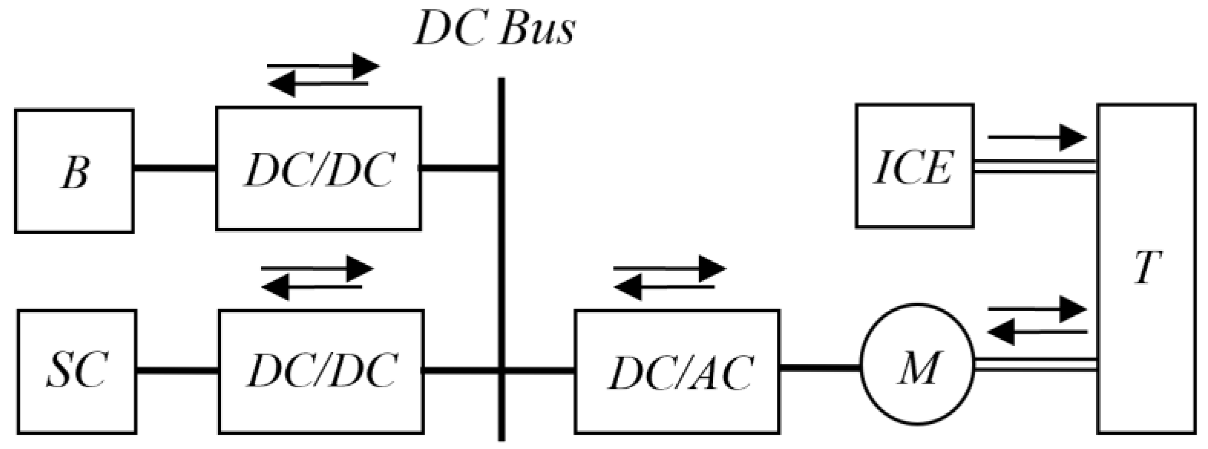
In [14,15], an improved version of a combined source with an energy storage device based on supercapacitors for a vehicle is proposed (Figure 1). The internal combustion engine (ICE) is the main power source; the electrical system, consisting of the electric machine (M), stand-alone inverter (DC/AC), batteries (B), and supercapacitor (SC) unit, constitutes the auxiliary energy source. To increase battery life, the SC unit is used as a power source. The energy stored in the SC unit and the B batteries is controlled by bidirectional DC/DC converters. The mechanical energy from ICE and M is channelled to the transmission (T). From this point onward, arrows show the directions of energy flows.
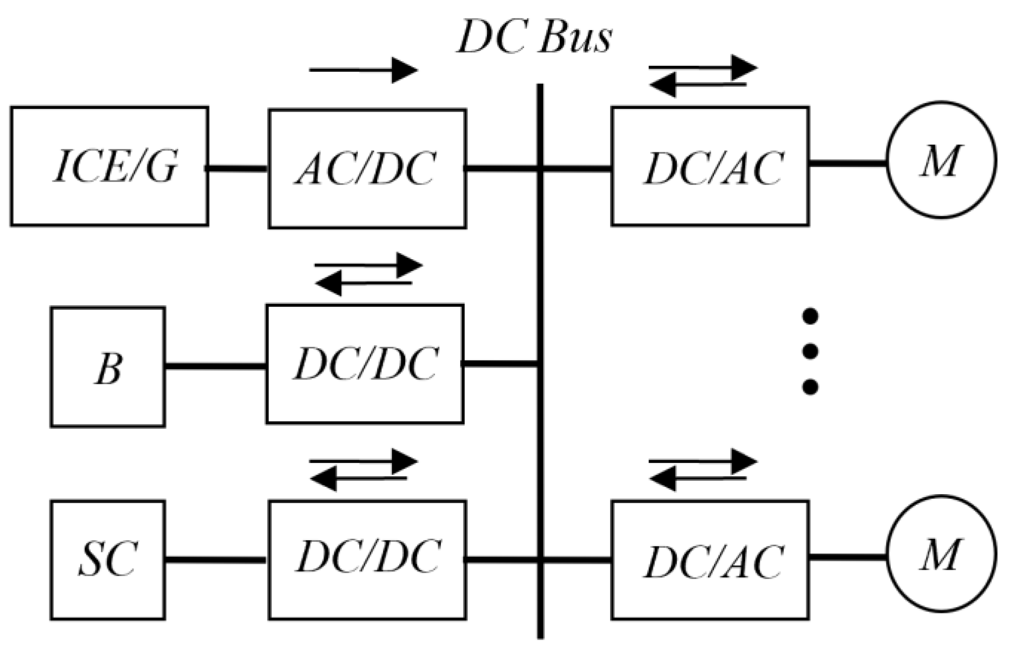
Hybrid energy sources with several auxiliary power sources are presented in [16,17]. Ref. [16] proposes power flow control algorithms for an all-wheel-drive serial hybrid electric vehicle with a diesel generator, a battery pack, and a supercapacitor pack (Figure 2). The diesel generator (ICE/G) is the main source of energy. It provides the average power of a vehicle. The SC supercapacitor bank satisfies the need for power during acceleration and deceleration. Battery B is used as intermediate storage for electric vehicle operation. The presence of three energy sources makes it possible to implement in military applications, not only high dynamic characteristics but also a stealth function.
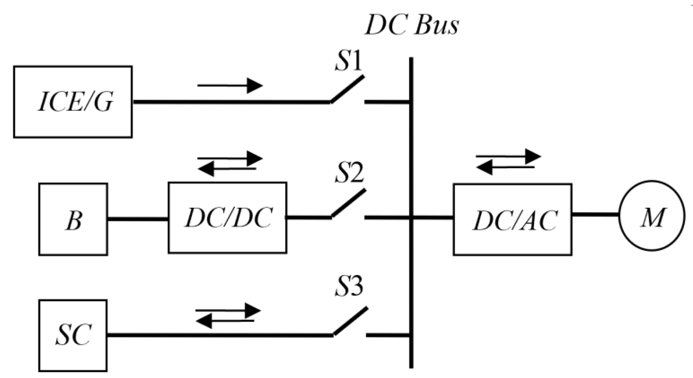
In [17], the strategy of controlling a hybrid power source in relation to the electric drive of combat vehicles is studied. When using a hybrid energy structure (Figure 3) with appropriate control technology, the hybrid energy source’s efficiency is improved. The energy management strategy of the B and SC units has extended battery life and improved system efficiency while delivering fuel savings. It should be noted that the bidirectional DC/DC converter is only in the battery circuit.
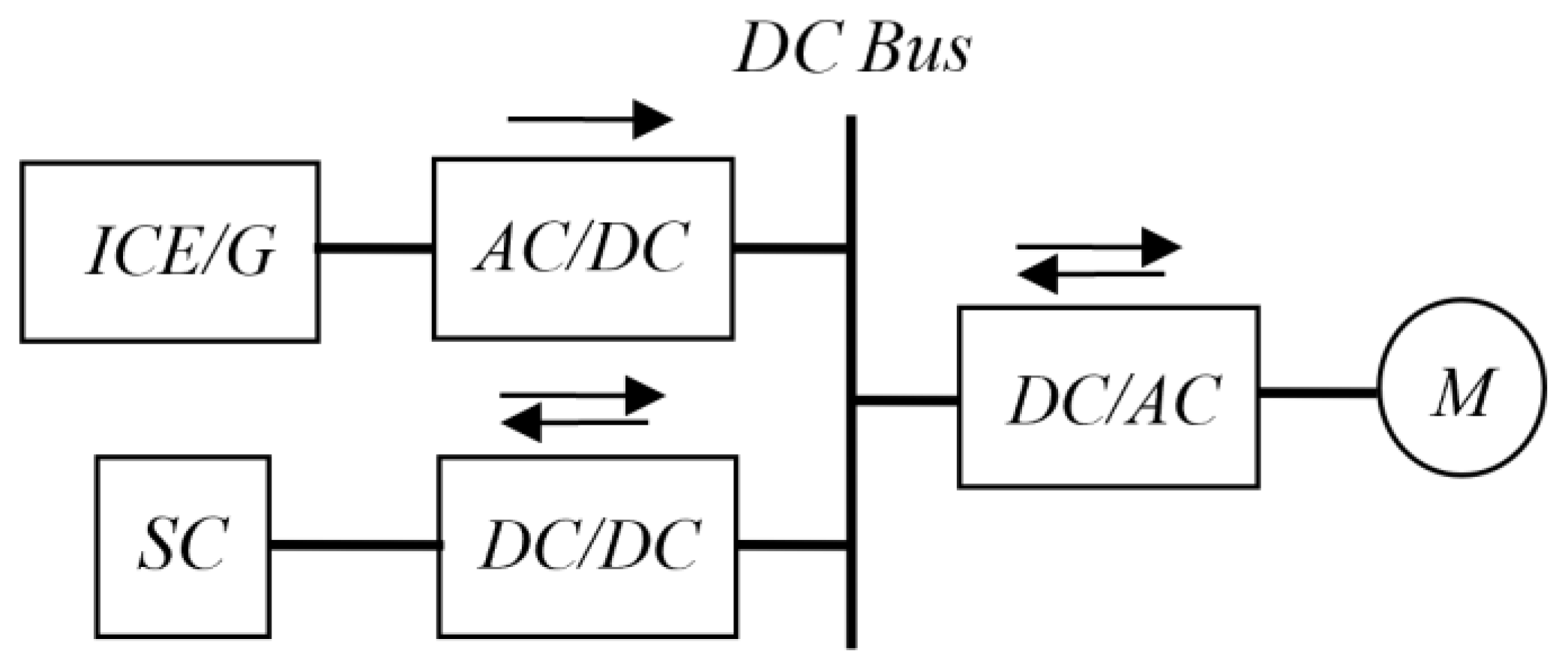
In [18], a diesel–electric drive system for an industrial truck with an energy storage system based on supercapacitors is considered. The energy source of an asynchronous electric drive consists of an ICE/G diesel generator with a rectifier at the AC/DC output, a bidirectional DC/DC converter, an SC supercapacitor module, and a stand-alone DC/AC voltage inverter that feeds the asynchronous motor M (Figure 4).
During the drive’s deceleration, the kinetic energy after conversion by the asynchronous motor is returned to the DC link via the inverter. In order to limit the DC link voltage during braking, regenerative braking energy is transferred to the supercapacitor module SC via a DC/DC converter. The energy stored in the SC module is fed into the DC link, thereby feeding the traction inverter when the induction motor needs more power. Thus, the traction drive’s energy consumption is significantly reduced.
2.1.2. Structures of Hybrid Power Supplies with a Storage Battery as the Main Energy Source
Hybrid energy sources with a battery as the main energy source are considered in [7,11,19,20,21]. These works can be characterised by the structure of a hybrid energy source, as shown in Figure 5. The main source of energy is the battery. It covers the drive’s average load. The SC unit provides, via a bidirectional DC/DC converter, the additional power needed for motor acceleration and takes power from the motor during deceleration.
In [11,20], designing and modelling a hybrid energy storage system used in light battery-powered electric vehicles are considered.
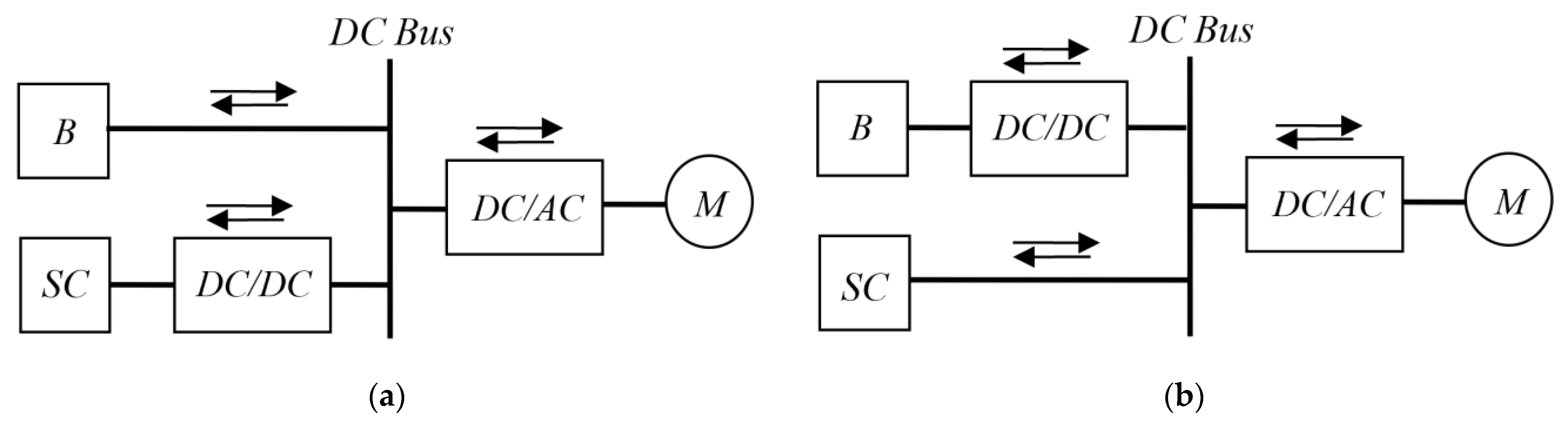
Ref. [21] analyses two semi-active configurations of a combined power source, including a semi-active supercapacitor module and a semi-active storage battery. The energy of one of the storage elements is run by a bidirectional DC/DC converter. The control strategy is based on the division of the power’s dynamic components required by the load. While the supercapacitor effectively provides the fast-acting dynamic power component during acceleration and deceleration, extra power is provided by the battery. The first topology (see Figure 5a) is preferable since it offers advantages in both efficiency and cost.
In [21], an energy storage device with a battery connected to the DC bus through a DC-DC converter and supercapacitors directly connected to the DC bus is analysed (see Figure 5b). The control strategy is also based on the division of the power’s dynamic components required by the load.
The following disadvantages of such a combined energy source can be noted. The inverter DC link voltage limits the SC unit’s output power. If the voltage in the DC link is low, the drive cannot provide the required peak power. In this configuration, all of the battery’s energy should pass through the DC/DC converter and, therefore, its energy efficiency will be reduced. Another disadvantage of this configuration is that a bank of high-voltage supercapacitors is required: the cost of the bank is usually quite high.
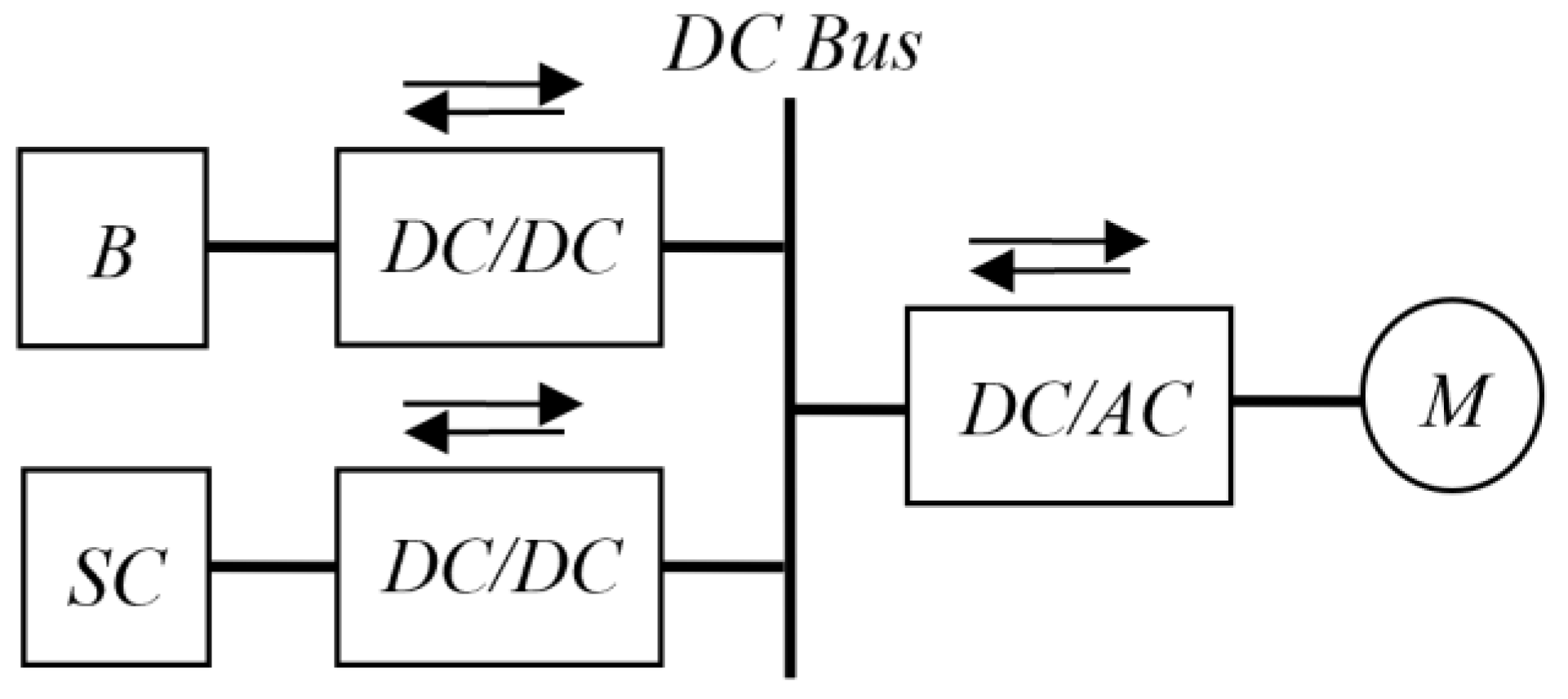
In [22], a traction drive consisting of a permanent magnet synchronous motor connected via a DC/AC converter to the DC bus (Figure 6) is considered. A feature of this circuit is the existence of two bidirectional DC/DC converters. The battery DC/DC converter increases the DC link voltage and provides intelligent battery management.
2.1.3. Structures of Hybrid Power Supplies with a Fuel Cell as the Main Energy Source
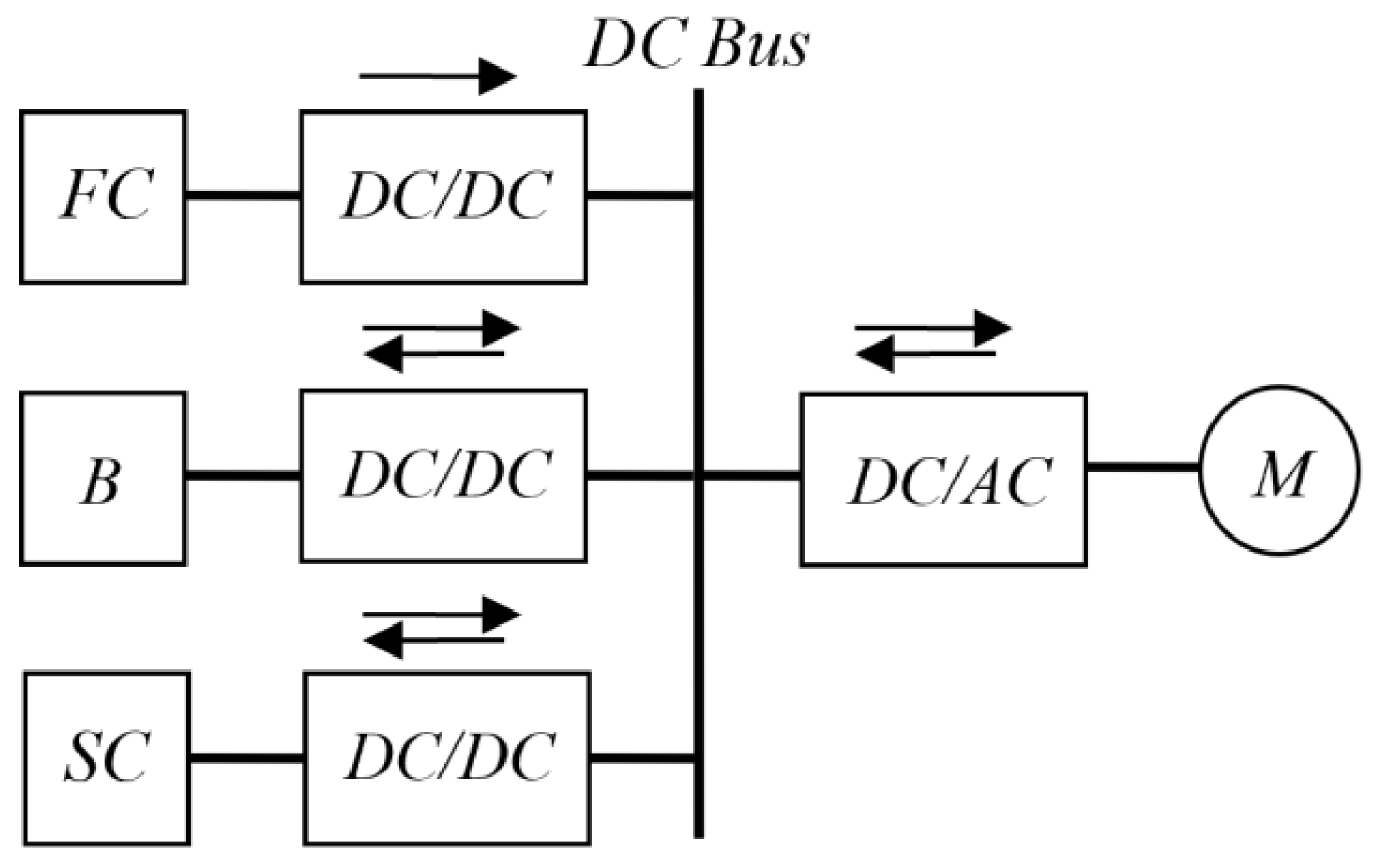
A fuel cell (FC) is an alternative use of green energy in in-vehicle systems. Most often, a hybrid source with a fuel cell is built as shown in Figure 7 [19,23,24,25,26].
A fuel cell as the main source of energy covers the average load of the drive and has a non-reversing DC up-converter that maintains a constant voltage according to a given reference value. An auxiliary SC source provides, through a bidirectional DC/DC converter, the additional energy necessary for the acceleration of the motor and receives energy from the motor during deceleration.
Hybrid vehicles equipped with a fuel cell and supercapacitors have the following advantages [19]:
- The fuel cell provides less current during transient operation;
- The fuel cell’s service life is increased;
- The energy autonomy of a hybrid vehicle is increased.
However, fuel cells have some technical limitations, such as low efficiency at low load levels, a high cost per watt, and slow dynamics in transient situations. For these reasons, fuel cells are not used in hybrid power supplies to meet full load power, especially during start-up and transient periods.
2.2. Hybrid Power Supplies for Public Transport Vehicles
Contemporary light rail vehicles and subway systems have high power peaks during acceleration and can convert energy during braking into electrical energy, feeding it back into the contact network [29,30]. However, this energy can only be used if there are other trains with high energy consumption next to the vehicle in braking mode. If this requirement is not met, then the braking energy will be dissipated predominantly in the vehicle converter’s braking resistors. It is important to store the braking energy in the train in order to use it during later acceleration. In addition, the high currents consumed by trains during acceleration entail large voltage drops on the line, which adversely affects the engine start mode. A reduction in energy consumption can be achieved if kinetic energy is used wherever possible [31]. Some pilot tests were carried out on a prototype commuter train equipped with an onboard supercapacitor energy storage device [32]. The tests show energy savings of around 30%. A typical diagram of an electric drive’s power part is shown in Figure 9. Here the main source of energy is a contact network, usually direct current. The auxiliary source is a set of supercapacitors with a bidirectional DC/DC converter.
The results of the theoretical and experimental studies presented in [29,30,31] show that the use of energy storage devices based on supercapacitors is a technically effective and feasible solution for reducing peak power consumption by up to 50% and energy recovery during braking by up to 30%. The use of supercapacitors makes it possible to reduce the current in the network by more than 50%, which leads to a reduction in losses and a decrease in the voltage drop in the contact network.
The use of an onboard [29] or stationary [33] energy storage device on a metro line makes it possible to ensure the constancy of the network power schedule and reduce energy losses in elements of the power supply system. In addition, energy storage on board can ensure a vehicle will be able to move to the next station in the event of a power outage [34].
2.3. Hybrid Power Supplies for Electric Drives of General Industrial Mechanisms
The electric drives of general-purpose, industrial-grade mechanisms, in which a tangible energy effect can be obtained from the use of supercapacitor energy storage systems, including the electric drives of cranes, passenger lifts, and freight lifts.
2.3.1. Hybrid Power Supplies for Crane Electric Drives
High operating costs present one of the shortcomings of crane electric drives with diesel engines [35,36,37]. This is due to the fact that at low loads, a diesel generator has low performance efficiency, which leads to high fuel consumption and an increase in the atmospheric emission of pollutants.
Another disadvantage is the presence of power peaks [38]. With the conventional power part, the electric drives of the crane’s lifting mechanism can be characterised by a high peak-to-average power ratio. In addition, they have the need to brake at rated power. The braking energy is about 30–40% of the consumed energy, which is dissipated in the braking resistor [35,38]. Finally, contemporary electric drives are sensitive to power failures [35]. The most common cause is voltage dip. The instantaneous root-mean-square voltage drop is in the range of 10% to 90% of the rated voltage, and the duration of the dip can be one minute [39]. Such a power failure can interrupt the electric drive and the process.
The use of hybrid power systems [40] in rubber-tired gantries (RTG) compared to diesel ones can reduce CO2 emissions by 60–80%, and maintenance costs by about 30% [40]. The use of supercapacitor energy storage to reduce peak consumption and gas emissions in RTG crane systems resulted in fuel consumption savings of 35% and CO2 emissions reduction of 40% [41]. The payback period was three years, taking into account the difference in the cost of the engine generator and the future mass production of supercapacitors. In addition, the overall weight and volume are reduced by 15% compared to a conventional diesel generator, even with an additional DC-DC converter and supercapacitor bank. In addition, a DC/DC converter regulates the rectifier current and reduces the drive input current’s total harmonic distortion by up to 30% [35]. The DC bus voltage can stabilise irrespective of the load and mains voltage fluctuations.
In [38], the advantages are noted as follows:
- The possibility of maintaining a continuous electric power supply to the system is improved;
- System functionality, including the braking ability, is not related to network reliability;
- The mains peak power can be regulated, and the influence of the drive on the network is greatly reduced. This is especially important in the case of a weak power supply [37].
Compared to the typical diesel generators used in conventional RTG cranes, a 35% reduction in fuel consumption has been achieved as a result of pilot testing. During the tests, the reduction in fuel consumption was 52.2%.
In [42], the economic efficiency of reducing the peak load in ship-to-shore cranes with an energy storage device based on supercapacitors was studied. A significant reduction in peak consumption was obtained with the levelling of the load curve.
The use of an energy storage system in [43] made it possible to significantly reduce the required power of RTG cranes by reducing the power peaks that occur at the beginning of the lift.
Combined energy sources for cranes with an internal combustion diesel engine as the main energy source are considered in [36,37,41,44]. These works employ the structure of the combined energy source shown in Figure 4.
Ref. [36] proposes an energy storage system based on supercapacitors and batteries to minimise the effect of load changes on a diesel generator by using two bidirectional DC/DC converters to link SC and B. This solution allows the SC and B processes to be controlled independently, respecting the limitations of dynamics. The use of SC and B to support the diesel generator in transient conditions can improve energy performance during rapid load changes.
2.3.2. Hybrid Power Supplies for Electric Drives of Lifts
- The existence of peak power, the ratio of which to average power can exceed a tenfold value [49];
- The reliability of lifts.
One of the possible ways to solve these problems is by using supercapacitor energy storage systems [49,53,54,55]. In lifts, the direction of electricity flows depends on both lifting and lowering the cabin [49,50,51,55,56]. When a lift goes up with a full load or down with an empty load, the maximum amount of energy is consumed. When a lift moves down with a full load or up with no load, the maximum amount of energy is generated. In conventional electric drives, this energy is dissipated in the braking resistor [57]. When an energy storage device is used, the stored energy in the supercapacitor is used to accelerate the drive. In this regard, the power, which should come from the network, will decrease, thereby saving energy [50,58,59]. Combined power supplies for lifts are made according to the diagram shown in Figure 10 [49,51,53,55,56].
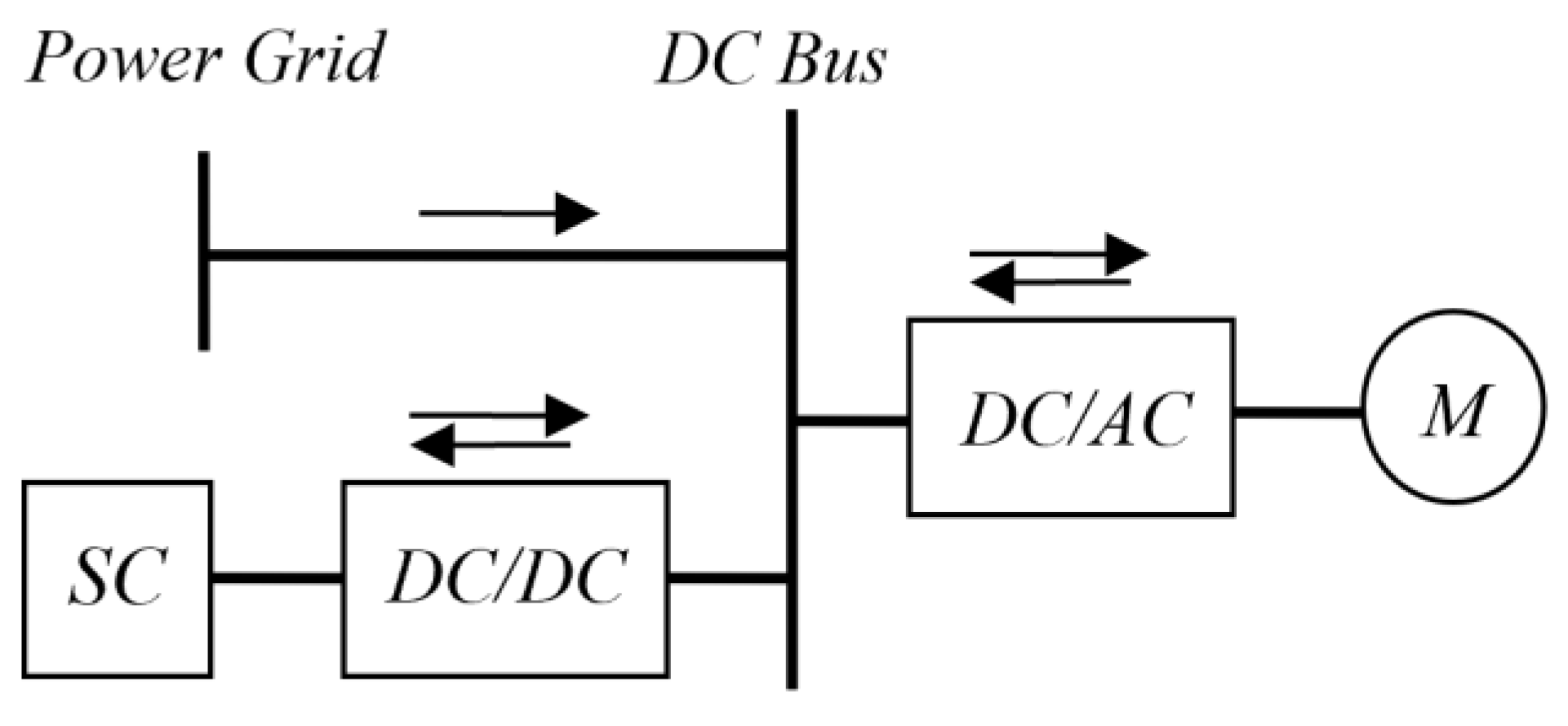
The reliability of lift drives during a power outage can be ensured by introducing a fuel cell into the power supply system as a backup power source [50], as shown in Figure 11.
Smoothing power peaks are considered in [51,57]. It was shown in [52] that the use of supercapacitors provides significant energy savings, which can be up to 47.5% compared to a drive with a braking resistor. In [53], when modelling a lift electric drive with an energy storage system, an energy saving of 58.6% was achieved without taking into account the efficiency of the gear and pulley. Issues relating to improving the energy efficiency of lift electric drives with supercapacitors are also considered in [51,53,56].
2.4. Discussion
A review of the literature shows that the use of supercapacitor energy storage systems is promising in controlled electric drives, the operating cycle of which can be characterised by the existence of starting and braking modes. The energy efficiency of such electric drives can be improved by using combined power sources consisting of an energy source and a power source. The energy source covers the power consumed in the drive’s steady-state operation, and the power source covers the peak energy consumption at start-up; it receives the energy released by the motor during braking.
In circuit solutions for combined power supplies, the role of a power source is performed by supercapacitors, the charge/discharge of which is controlled by a bidirectional DC/DC converter.
Combined power sources with a supercapacitor energy storage system differ from conventional power sources in that they eliminate the redundancy of the installed capacity of the main energy source (diesel generator, battery, fuel cell): the consumption of input energy (fuel) is reduced, while the service life of the main source energy and the efficiency of the electric drive are increased.
The use of energy storage systems based on supercapacitors, in addition to energy saving, also allows a number of other problems to be solved:
- With appropriate management of the distribution of the energy flow of sources, smoothing the peaks of power consumption from the main energy source can be ensured;
- Stabilisation of the voltage level of the main source when the drive load changes;
- Lower operating costs;
- Energy quality problems, which arise if the regenerated energy is fed into the local grid, can be avoided.
3. Auxiliary Power Topologies
3.1. DC-to-DC Boost Converter Topology
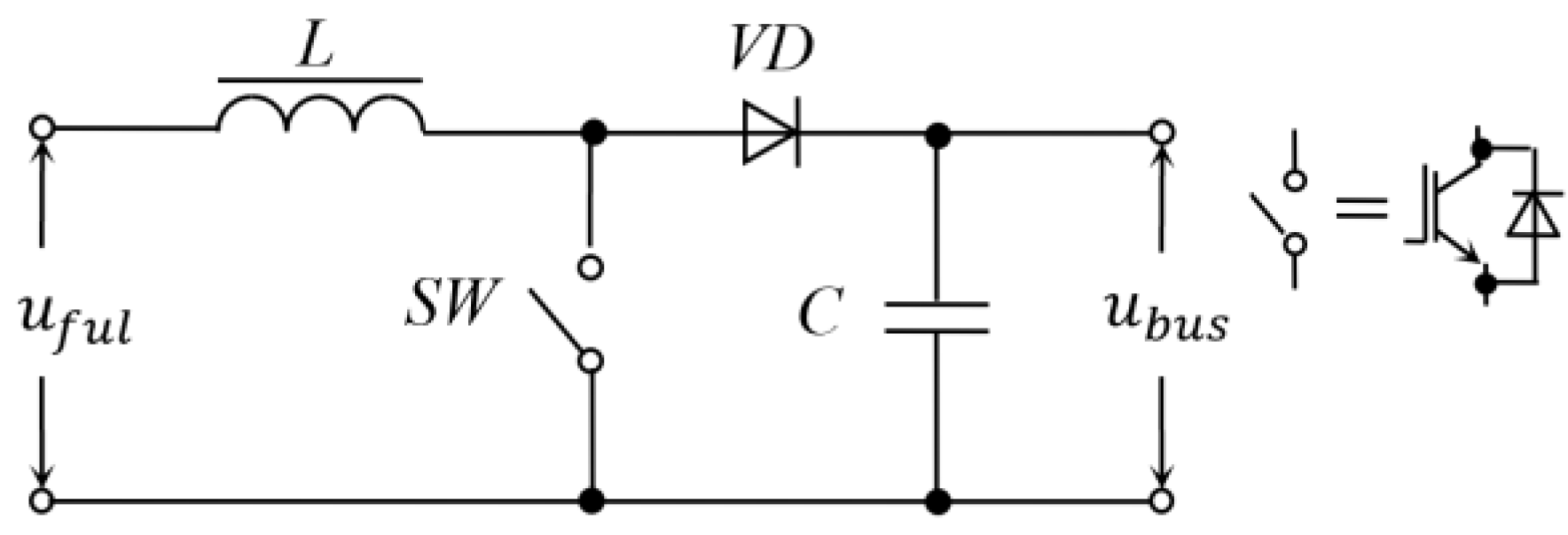
The simplest design used to increase and stabilise the voltage of fuel cells and batteries in the hybrid sources of electric vehicles [19,23,24,25,26,60] and lifts [50] is the circuit shown in Figure 12. A similar circuit is used in electric drives with storage devices to provide power in the event of an interruption in the mains voltage [61].
In such a converter, energy accumulation in the inductance L and the transfer of that energy to the DC link (C capacitance) of the frequency converter is provided separately in time. This process is controlled by a semiconductor switch (SW). The desired voltage transfer coefficient is achieved by changing the ratio between the duration of those two processes.
3.2. Topologies of DC-DC Buck-Boost Converters with a Single-Phase Conversion Method
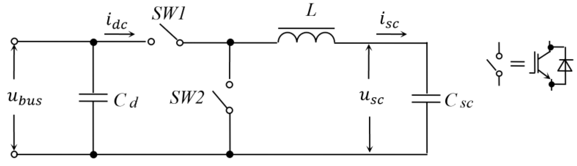
In cases where galvanic isolation between the supercapacitor module and the hybrid power supply’s common DC bus is not required, a simple DC/DC up/down converter is used. Figure 13 shows a diagram of such a converter. In what follows, we will call it the typical topology.
Given certain conditions, current can flow in two directions, from the common bus to the supercapacitor module (Csc) and vice versa. Two semiconductor switches (SW1 and SW2) are used to control the inverter. The principle of the circuit’s operation has been described in many publications, so it is not considered here.
The key advantages of the typical topology are simple structures, high reliability, relatively small dimensions, relatively small power losses due to single energy conversion, and fast response to load changes with an appropriate control system [16,20,62]. Due to these advantages, the typical topology of the DC/DC converter with a single-phase conversion method has become widely used. In particular, it is used in diesel generator sets [36], the rail sector [29,30,31,32], transport systems [11,16,19,23,24,25,26,63,64], cranes of various types [45], and lifts [50,53,56,57].
The type of DC/DC converters with a single-phase conversion method also includes the topology of a three-level converter [20,62,65] for supercapacitor energy storage devices. Figure 14 shows a diagram of a three-level DC/DC converter.
The converter consists of four current bidirectional semiconductor switches SW1-SW4, a filter inductor L in the circuit of the supercapacitor module Csc, and two input filter capacitors Cd1 and Cd2. The input filter capacitors are used as a capacitive voltage divider for the DC link. Key control signals are generated by two pulse-width modulators.
Three-level converters have a number of advantages over two-level converters [65]. The choke inductance L is 25% of a two-level DC/DC converter at the same current ripple, which reduces the choke volume by a factor of four. In this regard, the losses are reduced several times.
Another advantage is the nominal voltage of the switches, which is half that of a conventional two-level converter. This affects the switching losses. The total switching losses are 50–75% of those of a two-level converter. Conduction losses can also be lower depending on the switching technology.
In addition, when using a three-level topology, there is no need to balance the voltages when connecting capacitors in a series with a passive resistive circuit. Finally, in a three-layer topology, electromagnetic compatibility is improved.
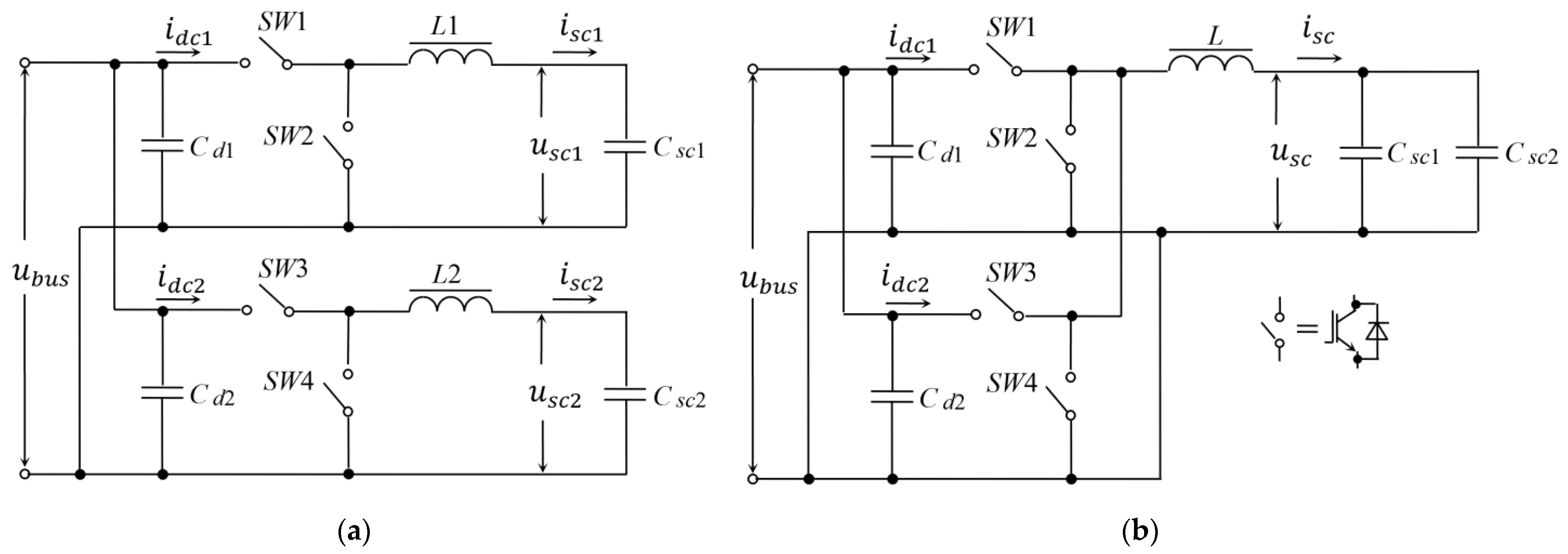
However, as shown in [27], a typical converter topology does not always guarantee the energy needed for a hybrid vehicle. In addition, the efficiency of the typical topology at a power of 216 kW, for example, was below 85%. In this regard, parallel topologies of DC/DC converters have been proposed [27,66], as shown in Figure 4.
The first version of a DC/DC converter parallel topology (Figure 15a) consists of two identical supercapacitor modules, two typical DC/DC converters, two capacitors (Cd1 = Cd2) for filtering the DC bus voltage, two inductors (L1 = L2) for smoothing the current of supercapacitor modules (Csc1 = Csc2). The dynamics of the current control are satisfactory. The efficiency is almost the same as for the typical topology. This topology ensures minimal maintenance costs when one converter or one supercapacitor module fails.
A disadvantage is the possible unbalancing of the converter modules due to differences in their internal resistances or control channels.
In order to reduce the size of the smoothing reactor L in the common circuit of the two supercapacitor modules, a second parallel topology is proposed in [27], as shown in Figure 15b. The topology of the second version of the converter makes it possible to solve the problem of the imbalance of supercapacitor modules. The dynamics of the power supply to the vehicle are improved and the converter control strategy is simplified. This topology is not very sensitive to imbalance if one of the converter modules fails. The efficiency of such a converter coincides with the parallel topology of the converter shown in Figure 15a.
3.3. Topologies of Multiphase Up/Down Converters
Using a single-phase DC conversion method may not be the best solution, as high input current ripple can shorten the energy storage system’s life. The topologies of multiphase converters have aroused much interest in recent years [60,62,67,68,69]. Examples of the use of multiphase converters can be found in modelling and experimental studies of hybrid sources for urban transport [31,34,70,71], electric vehicles [18,21,22,60,72], cranes [41,42,46,47], excavators [73], etc.
The key characteristic of the multiphase conversion method is the organisation of alternation, i.e., phase shift by 360°/n, where n is the number of parallel channels (phases) and 360° is the switching period in the control signals of parallel-connected n single-phase converters. Figure 16 shows the topology of a three-phase DC/DC interleaved converter.
The multiphase interleaved conversion method provides the following advantages [18,41,44,60,62,72,74,75,76]. With it, all single-phase converters operate at the same switching frequency, but due to the phase shift between them, the ripple of the total current of the supercapacitors is significantly reduced. Sharing the total current of a supercapacitor module across multiple phases reduces the overall cost of energy storage. In addition, standard power modules for three-phase loads can be fully utilised in a three-phase design.
In such converters, both uncoupled and magnetically coupled smoothing chokes can be installed. The combination of a multiphase topology with a coupled choke design [75] provides additional benefits. With the same switching frequency, lower choke inductances can be achieved compared to multiphase converters without inductive coupling. This is essential to achieve a small size for mobile applications. In contrast to a multiphase converter with uncoupled chokes, the use of coupled chokes further reduces current ripple. The power losses and peak current requirements of the switches are reduced. In the context of the reduced phase current ripple, it becomes easier to ensure that the magnetic medium of the inductors operates in its linear range, which creates the prerequisites for the development of controllers for control systems that do not take into account changes in the parameters of the converter due to the effects of the saturation of the inductors’ magnetic circuit.
Finally, the benefits of interleaved DC/DC converters include high power capability, modularity, and improved reliability. The modular approach provides fault tolerance for the system in case of the failure of one module. The dimensions of the entire converter are smaller than a single DC/DC converter with a typical topology.
However, interleaved DC/DC converters have disadvantages. Possible non-ideal channels can cause an imbalance of currents in the converter chokes, which will lead to the loss of the advantage of suppressing ripple currents. In this regard, it becomes necessary to control the current of each inductor in order to evenly distribute the input current over all phases of the converter, which complicates the energy storage device’s control system.
3.4. Topologies of Up/Down DC-to-DC Converters with Voltage Level Adaptation via a Transformer
If necessary, the galvanic isolation between the supercapacitor module and the common DC bus of the hybrid source, as well as matching the voltage level between them, the DC/DC converters with a high-frequency electromagnetic transformer are used [49,60,77,78,79].
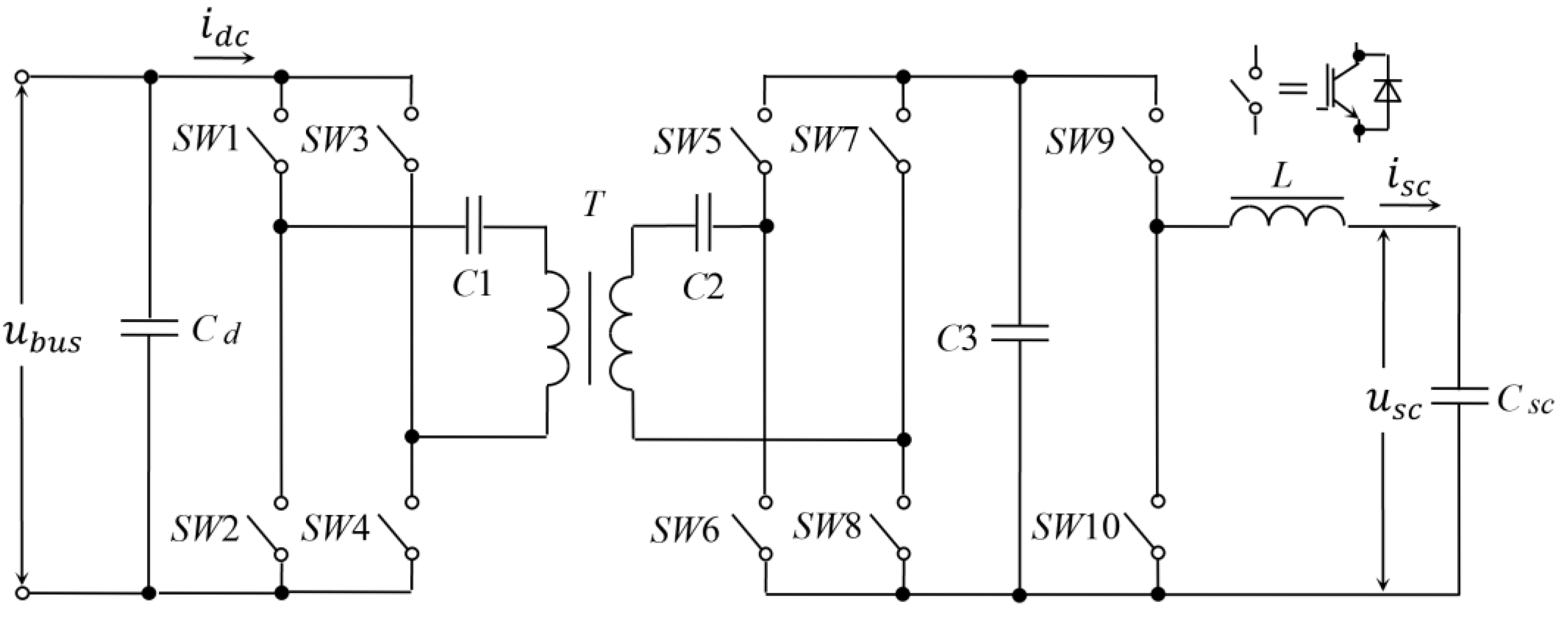
In view of a large number of circuit solutions, we restrict ourselves to two examples [49,77]. One of the possible solutions [77] is shown in Figure 17, where the high-voltage side of the transformer (T) is coupled to the common DC bus via a four-quadrant bridge (SW1–SW4 switches) operating in resonant mode. On the low-voltage side, there is the same bridge (SW5–SW8 switches) and an additional converter (SW9–SW10 switches) for changing the voltage at the terminals of the Csc supercapacitor module during charging and discharging.
The disadvantage of such a converter is threefold energy conversion, which reduces the overall efficiency of the converter [49], and design complexity due to the use of the resonance effect to reduce switching losses.
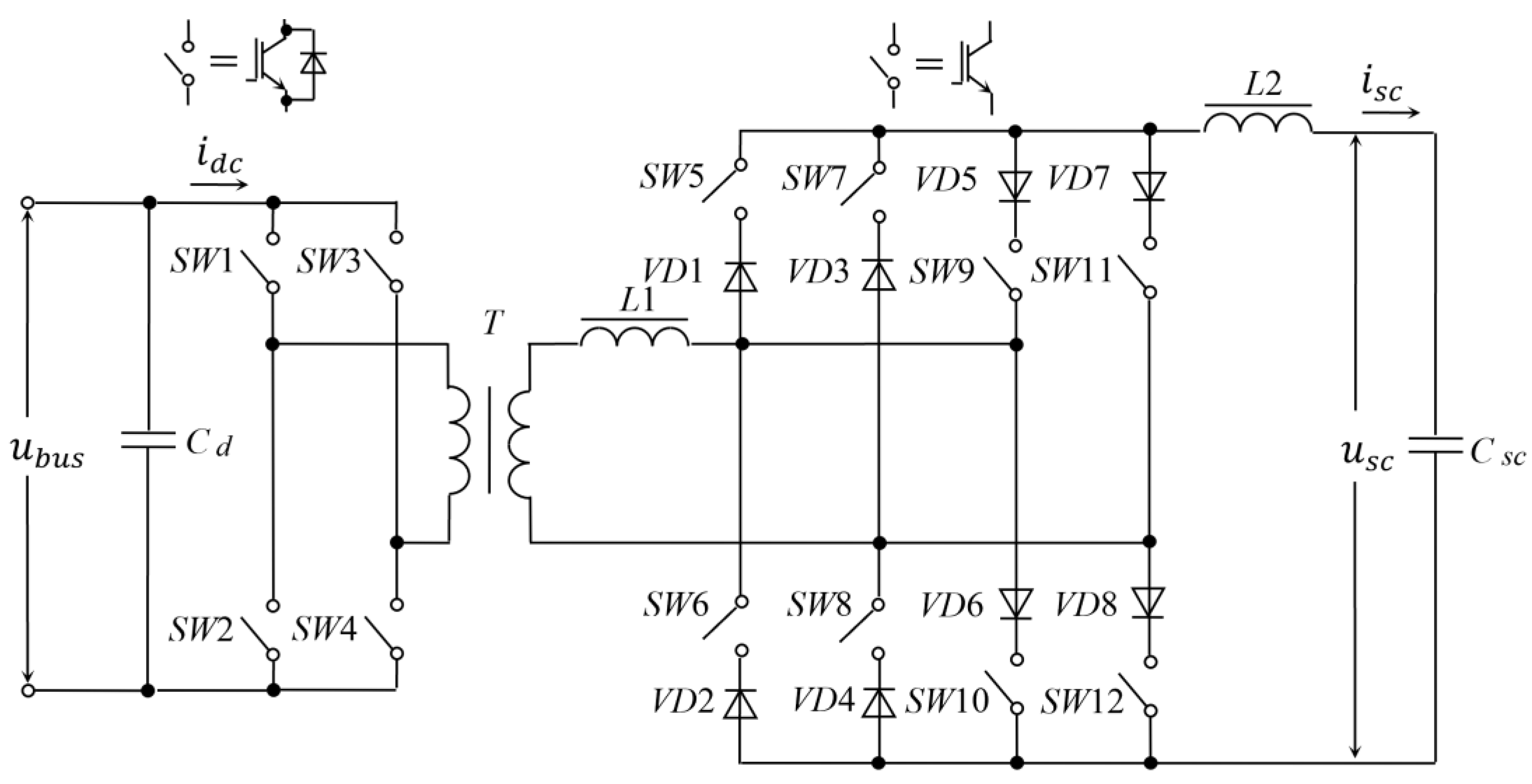
An alternative solution with higher efficiency is the soft-switched converter topology shown in Figure 18. The circuit uses two static converters. A voltage inverter (SW1–SW4 switches) run in the main frequency switching mode is installed on the high side of the transformer T. On the low side of the transformer T, a natural switching current inverter in a reverse topology with two anti-parallel bridges (SW5–SW8 and SW9–SW12 switches, VD1–VD4 and VD5–VD8 diodes, respectively) is used. The storage circuit consists of a series connection of a smoothing choke (L2) and a supercapacitor module Csc. This solution offers good flexibility to optimally select the voltage level of the supercapacitor module and the ability to reduce the number of components in the equalisation circuitry for series-connected supercapacitors.
3.5. Discussion
In low-voltage hybrid power sources for asynchronous controlled electric drives like supercapacitor energy storage devices, two topologies of DC/DC converters are widely used: a typical topology with a single-phase conversion method and topologies with a multiphase conversion method with a phase shift of 360°/n.
In high-voltage hybrid energy sources, a high-frequency transformer is a necessary element of galvanic isolation in supercapacitor energy storage circuits. This makes it easier to match the levels of the input and output voltages when they differ greatly by installing a transformer. The use of resonant inverters reduces the loss of active power at the intervals of turning on and off the switches.
The main design criteria are the minimisation of dimensions and power losses and the reliability of supercapacitor energy storage devices.
4. Structures of Control Systems for Auxiliary Power Sources with Supercapacitors
In regulated electric drives, auxiliary power sources are supplied with automatic control systems (ACS), which address such key challenges [80,81,82] as maintaining the voltage at the input of a stand-alone voltage inverter with a given accuracy to eliminate voltage surge during braking and maintaining the charge/charge current within the specified limits of discharge and voltage at the supercapacitor module’s terminals. This review of ACS for auxiliary power sources will identify the general composition and principles of the regulation of variables, the types of regulators, and the criteria for setting control systems.
As the analysis of the literature on this topic shows, single-circuit [11,18,19,20,23,27,36,41,64,71,72,83,84], double-circuit [16,22,34,53,70,73,85,86], and three-circuit [81,82,86] control systems are most commonly used.
4.1. Composition and Principles of Regulation of Variable Single-Circuit Automatic Control Systems
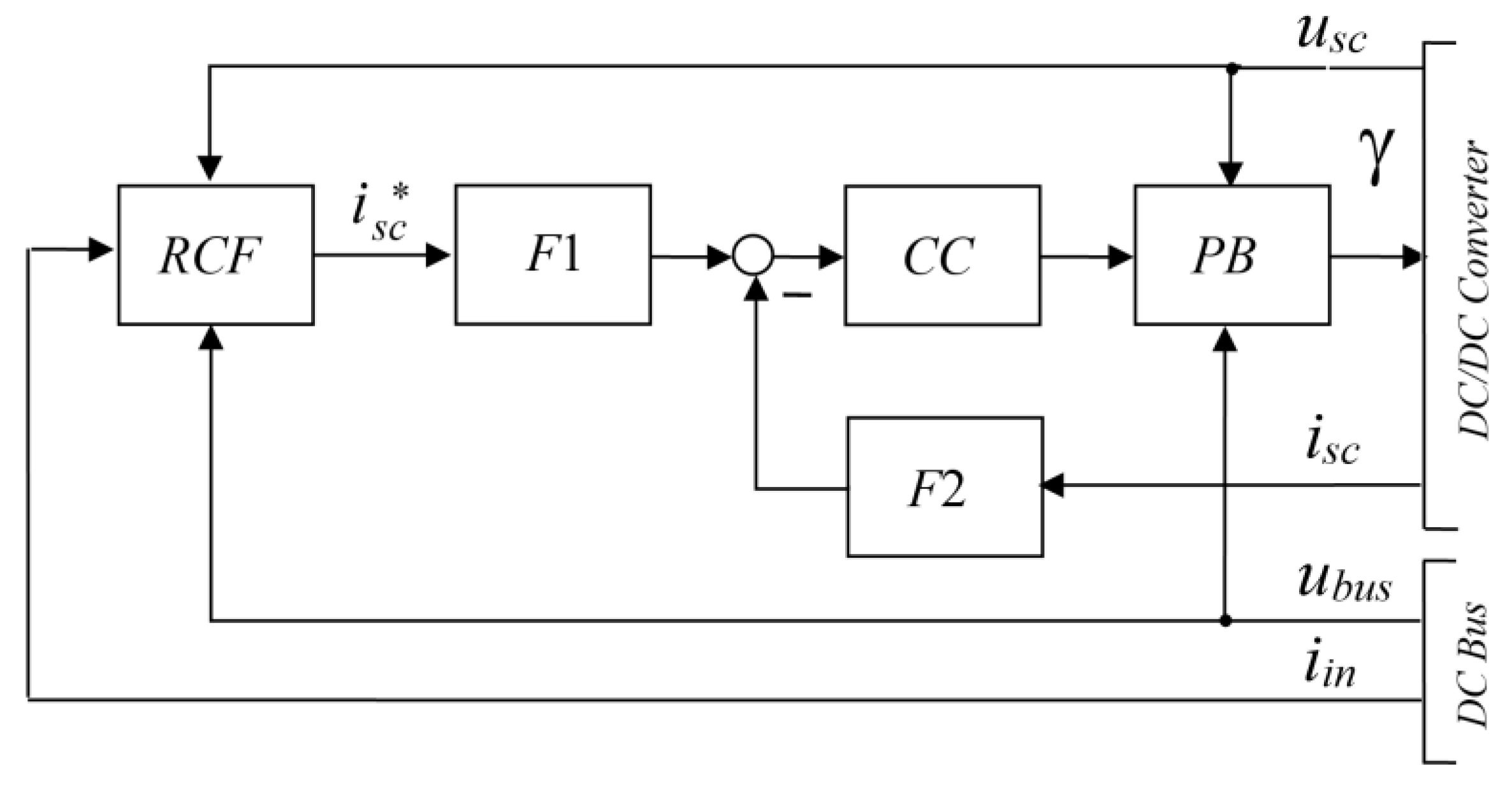
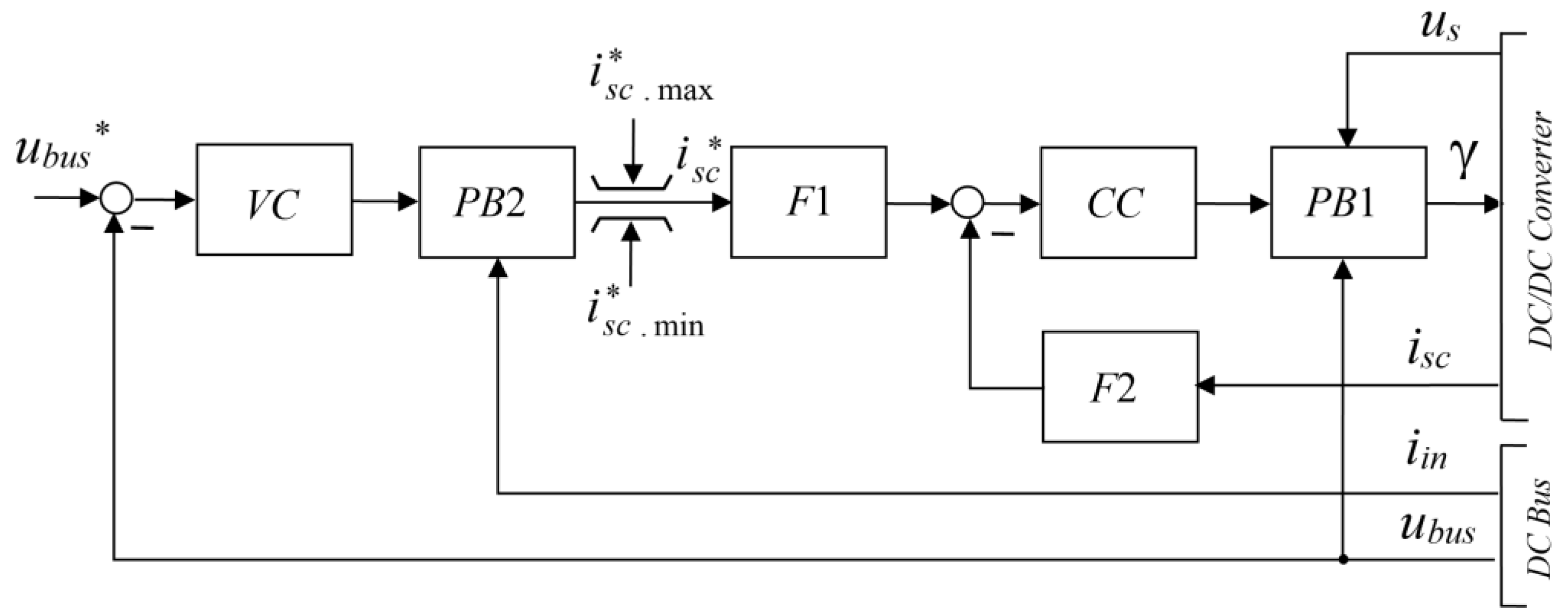
When using a typical DC/DC converter topology (see Figure 2), the controlled variable of single-circuit ACS is the current of the supercapacitor module (isc). It is common to all such structures to use the input current (iin′) of the voltage inverter supplying the asynchronous motor as initial information; additional information is used for calculating the reference current (isc*) of the supercapacitor module. Figure 19 shows a generalised diagram of a single-loop current ACS isc, where CC is a current controller, PB is a pre-emption block, F1 and F2 are filters, and RCF is reference current forming. The designations of the variables in the circuit correspond to Figure 2.
The non-linear properties of the DC/DC converter as a controlled element determine the introduction of perturbation pre-emption into single-circuit ACS, one of which is the DC bus voltage (ubus). For this purpose, the ACS structure has a PB lead block, which increases the current control system’s accuracy. However, if the CR controller is a relay type, the lead block is excluded due to the invariance of relay ACS to disturbances. In single-circuit automatic control systems, the usefulness of installing filters according to the task and in the current feedback channel is substantiated. In this case, the number of degrees of freedom increases, and high-frequency noise is also suppressed.
Differences in the single-circuit ACS current isc are in the algorithms for the creation of the reference current isc*, the structure of the controller, and the criteria for setting the control system.
In [19,23,27,36,64], the reference current isc* is calculated from the input current usc of the voltage inverter, taking into account additional information about the DC bus voltage ubus and the supercapacitor voltage usc. The need for these voltages can be explained by the inequality of the iin and isc currents. The coupling coefficient between these currents is obtained from the power balance equation at the input and output of the DC/DC converter in the absence of losses. In addition, for the distribution of energy between the main and auxiliary sources in the transient modes of the electric drive, the task for the current ACS is calculated, taking into account the release of the high-frequency current component iin.
As far as the structure of the current controller is concerned, a polynomial controller is used here, the setting criterion of which is the minimum of the static error in interference suppression. A polynomial controller is an alternative to a conventional proportional-plus-integral controller. It provides a faster response and effectively suppresses interference compared to a conventional proportional-plus-integral controller [87].
The algorithm for calculating the reference current also provides for limiting the voltage of the supercapacitors at the level of the highest and lowest values in order to avoid wear to the supercapacitors. The proposed limiting strategy is implemented by adding constant offsets to the reference current’s dynamic component. The algorithm for calculating the reference current of supercapacitors is described by the equations [36]:
where isc.d* is a dynamic component of the reference current; isc.o* is the permanent current offset provided by the supercapacitor voltage limiting algorithm; iin* is a high-frequency component of the inverter load current; and F is a filter operator that extracts the mid-frequency component of the load current.
In [27], the reference current isc* in boost mode is also created based on the power balance between the supercapacitor module and the DC bus, taking into account the power losses in the DC/DC converter through its efficiency:
where idc* is the desired value of the external current of the DC/DC converter; udc is the external voltage equal to DC bus voltage; and η is efficiency of the DC/DC converter in boost mode. In buck mode, when the supercapacitors are being charged, the reference current isc* is set as constant.
Thus, in the algorithm for generating the reference current, instead of the load current, the external current of the DC/DC converter is taken, which, with a high-quality ACS, is equal to the iin current to within the tracking error.
Another feature of ACS is that, according to the reference current, a lag filter is installed, providing, with appropriate matching of its time constant with the parameters of the proportional-plus-integral controller, the damping coefficient of the response of the closed automatic control system equal to 0.707, which corresponds to the Butterworth criterion for a second-order filter.
It is noted in [88] that in light transport systems, the reference current of a supercapacitor module depends on the adopted energy strategy. For example, in applying onboard supercapacitor storage, the reference current for charging and discharging the supercapacitors is calculated from a train’s kinetic energy by knowing its actual speed. However, the algorithm for calculating the reference current is not disclosed.
In [83], a supercapacitor energy storage device as a source of peak power for hybrid electric vehicles is designed and simulated. The high-level controller generates the isc* current required by the supercapacitor module using the measurement of the load current iin of the inverter and the supercapacitor module voltage level usc, which corresponds to the state of charge corresponding to peak power. In this case, the load current is divided into the main and peak parts of the load current. The purpose of the ACS is to transfer the first part of the load current to the main power source and extract the peak current component from the auxiliary power source. During vehicle acceleration, both the main power source and the peak power unit provide the necessary power for the electric drive. An increase in current consumption from the main power source will be mitigated by supplying current from the supercapacitors through the boost converter.
In [11], the reference current for the ACS is generated based on the voltage of the battery used as the main power source, the load current iin, the speed of the vehicle, and the state of charge of the supercapacitors.
Sliding mode controllers are also used in single-circuit current ACS. Noteworthy is the active power filtering method developed in [89] to reduce battery current ripples in hybrid electric vehicles in order to extend service life. The DC bus current is decomposed into low-frequency and high-frequency components using an improved real-time fast Fourier transform. The DC/DC converter of the auxiliary power source processes the high-frequency and part of the low-frequency components during the drive transient. In this case, high-frequency current surges and battery ripples are eliminated to a certain extent. Consequently, battery life will increase. Thus, in consuming the peak power of the electric drive, for example, when accelerating or lifting the vehicle, the supercapacitor module also becomes an energy supplier. In this case, the low-frequency components of the DC bus current should be reasonably distributed between the supercapacitor energy storage and the battery as the main energy source, taking into account their respective power density. As in previous works, the current of the supercapacitor module is considered an adjustable variable. In this case, the output signal of the reference current on the high-voltage side of the DC/DC converter is converted into a reference current on the low-voltage side in observance of the law of conservation of power and the calculated efficiency. The sliding control method is also used in [90]. Where the supercapacitors are connected similarly to Figure 4. The energy storage system is used to smooth the peak loads of the generator in the electric aircraft network.
A bidirectional DC-DC converter using chattering-free fixed-boundary-layer sliding mode (FBLSM) control is used to control the DC/DC converter. It is important to note that the FBLSM control strategy is applied in this study to improve the tracking accuracy of the isc* current and the robustness of the ACS of the supercapacitor storage.
If the auxiliary power source is a multiphase topology DC/DC interleaved converter, there are additional differences in the controlled variable. In [18], a method for controlling the current of a three-phase DC/DC converter with alternation is proposed. In the developed approach, only one phase current and two differential currents are directly controlled, that is, the total current of the supercapacitor module is controlled indirectly. Both the DC link voltage and the supercapacitor module voltage need to be measured for monitoring and preemptive control. A proportional-plus-integral controller is installed in the ACS.
Ref. [84] presents a single-circuit version of the ACS of a supercapacitor energy storage device as applied to highly dynamic industrial electric drives. In the single-circuit automatic control system, instead of the controlled variable current of the supercapacitor module, the external current idc of the DC/DC converter is adopted. Then there is no need to recalculate the load current, in which an error is introduced that is unacceptable from the point of view of stabilising the DC bus voltage in industrial electric drives. It was found that a single-circuit automatic control system has an increased sensitivity to errors in the supercapacitor charging mode, which leads to a decrease in the accuracy of stabilising the DC bus voltage during the braking of the electric drive. Another feature is that the current controller is synthesised according to a technique that involves tuning a closed loop to a modular or symmetrical optimum (tuning to a modular optimum is equivalent to tuning according to the Butterworth criterion). In this case, the structure of the current controller differs from the structure of a proportional-plus-integral controller: at the output of a linear corrective link, a signal is generated in the form of a sum of proportional, integral, and integral quadrature components. After the introduction of the compensating signal ubus, the corrected signal is fed to the input of the first-order low-pass filter, which limits the bandwidth of the ACS current and filters high-frequency noise. The introduction of pre-emptive control ensures constant gain in a closed current loop idc when changing the mode of the DC/DC up/down converter.
An essential element of a single-circuit automatic control system is the introduction of the voltage limiting unit usc at the terminals of the supercapacitor module at the pre-charge stage and during the further operation of the electric drive. In addition, a limitation of the charge/discharge current of supercapacitors is introduced.
4.2. Composition and Principles of Regulation of Variable Two-Circuit Automatic Control Systems
In two-circuit ACS, the internal circuit is the current regulation circuit of the isc supercapacitor module or the external current idc DC/DC converter. The external circuit is the voltage regulation circuit ubus of the DC bus. A generalised diagram of the two-circuit ACS is shown in Figure 20, where CC is the current controller, VC is the voltage controller, PB1 and PB2 are pre-emption blocks, and F1 and F2 are filters.
A signal corresponding to the reference desired voltage (ubus*) of the DC bus is applied to the outer circuit input. The output of the voltage controller creates the reference value isc* for the internal current circuit, that is, the cascade topology of the ACS is used. The advantages of two-circuit automatic control systems include the possibility of more effective suppression of disturbances and qualitative limitation of the controlled variables by limiting the reference signals isc* and ubus* of the controlled variables.
Dual-circuit automatic control systems have been applied in hybrid power systems for traction applications [34,70,88,91,92,93], lifts [53,56], excavators [73], industrial drives [80], and hybrid electric vehicles [87].
The main differences between two-circuit automatic control systems of auxiliary sources based on supercapacitors are as follows.
In [56], a lift electric drive is described. The supercapacitor energy storage ACS has two proportional-plus-integral controllers in a cascade topology to control the voltage ubus and current isc. The proposed control chart has a set of two fuzzy logic controllers for adjusting the DC bus reference voltage to take into account the change in the AC mains voltage in combination with the lift’s operating mode. Keeping a record of changes in the supply voltage can be explained as follows. In a traditional dual-circuit ATS, the applied reference voltage in the DC link is constant. If the AC mains voltage is constantly at a nominal value, the energy storage device’s expected performance can usually be achieved. However, if there is a change in the AC mains voltage, and although the energy store can absorb braking energy or supply energy to the motor, the energy store’s performance may be degraded. From this, it is concluded that it is necessary to take into account the change in the AC mains voltage in order to achieve optimal performance for an energy storage device based on supercapacitors. In particular, the maximum absorption of braking energy can be achieved, and the necessary energy can also be provided when accelerating the engine from supercapacitors. Thus, energy consumption from the network is reduced and, consequently, the efficiency of the lift electric drive is improved.
The fuzzy logic controller regulates the reference voltage in the DC link depending on the drive’s load mode. In addition, on-line correction of the parameters of the proportional-integral DC link voltage controller according to the load conditions is provided to improve the performance of the supercapacitor power source.
In [53], two controllers with fuzzy logic are proposed to achieve the following goals of controlling a supercapacitor energy storage:
- Charge/discharge of supercapacitors during engine braking/acceleration;
- Prohibition of charging supercapacitors if the voltage is higher than the maximum value, and prohibition of discharging supercapacitors if the voltage falls below the minimum value;
- Limiting the discharge/charge current of supercapacitors at the level of the highest allowable current;
- Stabilisation of the DC link voltage.
In [80], predictive control for a supercapacitor energy storage device is proposed, which has been tested in the field of automatic cargo storage.
The problems of managing stored energy are thus:
- Monitoring the voltage on the DC bus to avoid excessive voltage surge when the drive is decelerating;
- Use of the energy recovered during the braking phase to reduce the energy given off by the network and increase the electric drive’s overall efficiency.
An auxiliary AC/DC converter is used to determine the DC link voltage reference. Its function is to control the change in the mains voltage in order to avoid introducing incorrect reference values ubus*.
The determination of the supercapacitor reference current isc* is based on an analysis of the instantaneous power required by the capacitors in the DC link. The energy to be exchanged between supercapacitors and DC link smoothing capacitors can be calculated as follows:
where C is the capacitance of DC link capacitors.
After assessing the change in the DC voltage, the average value of the supercapacitor current is determined, which provides the above energy for the period T:
where T is the required length of energy recovery time. Determination of the current value of the current im and time T depends on the sampling time Ts of the control unit, the system parameters, and the operating mode.
Next, we explain the idea of predictive control with the example of calculating the reference current in the boost mode of a DC/DC converter. With the supercapacitor current prediction performed according to an analytical expression, the steepness of the current at the discharge stage is estimated:
where L is the smoothing choke inductance in the supercapacitor circuit.
After determining the relationship:
at a fixed value of Ts, the reference current of the supercapacitors is calculated to transfer the energy necessary to restore the voltage of the DC link capacitor:
For testing isc*, a relay controller with hysteresis is recommended.
The results achieved with modelling and experiments show the feasibility of the proposed predictive control system. There is good tracking of DC bus reference voltage in both boost and buck modes while the overall system efficiency is improved.
Stabilisation of the DC bus voltage ubus becomes especially important when the main source has a high impedance (for example, a fuel cell as the main power source) and the load requires a hard bus voltage [93]. It is noted that the voltage and current controllers should compensate for the influence of disturbances: when regulating the current, it is necessary to compensate for the voltage at the terminals of the supercapacitor module, and the voltage circuit should eliminate errors caused by the load current (to compensate for the influence of voltage usc and load current iin between current and voltage controllers in the structure (Figure 9), PB1 and PB2 feed-forward units are installed, respectively). Therefore, proportional-plus-integral controllers are used to obtain static errors equal to zero. There is a difference in the circuit adjustment criteria. The current controller should follow a constantly changing reference with a slowly changing disturbance. While the function of a voltage controller is usually reduced to maintaining a constant voltage and compensating for a rapidly changing load current. Therefore, the poles of the two circuits are different. In this regard, it is recommended that the current loop be tuned for optimal damping of the response. Good interference suppression can be achieved by placing the poles, resulting in a symmetrical plot of the voltage open-loop logarithmic frequency response.
Ref. [85] presents a power supply system for hybrid electric vehicles. A fuel cell with an appropriate control system is used as the main energy source. The auxiliary power source is a supercapacitor energy storage.
To control the energy exchange between the DC bus and the main and auxiliary sources, three modes of operation are distinguished:
- Charging mode, in which the main source supplies energy to the auxiliary source and the load;
- Discharge mode, in which both the main and auxiliary sources supply energy to the load;
- Recovery mode, in which the load supplies energy to the energy storage device.
The auxiliary power source is equipped with a dual-circuit automatic control system. The relay current controller isc is installed in the internal circuit. A reference value for the internal loop is generated by the DC bus voltage regulation loop, which uses the capacitive energy of the DC bus as a state variable and the power of the supercapacitors to calculate the reference current for the supercapacitor current regulation loop.
The external control loop has a proportional-plus-integral controller of the capacitive energy ebus of the DC bus. A function called “ebus/ubus“ is used to match the reference value and feedback value of the capacitive energy controller with the reference value e*bus and the feedback control value ebus.
The reference current iin* is calculated by dividing the signal from the output of the capacitive energy controller by the voltage usc of the supercapacitors and is limited to keep the voltage usc within the interval [usc.min, usc.max]. In other words, a usc voltage-dependent reference current limit iin* is used.
Ref. [87] describes a two-phase alternating up/down converter coupled with a supercapacitor for stabilising automotive power networks. For rapid regulation of the DC bus voltage, a cascade control topology with an internal current loop isc and an external voltage loop ubus is also chosen here.
Based on the analysis of the averaged model of a DC/DC converter with a supercapacitor module connected through a smoothing choke, the article discusses compensating for non-linearities inherent in an energy storage device as a controlled element. Disturbances caused by voltages on the DC bus and supercapacitors are compensated for (PB1 unit in Figure 9) because they can be measured. At the same time, the perturbation caused by the change in the gain during the transition from the decrease mode to the increase mode is compensated approximately. A feature of the ACS current is that it takes into account the dead time during the transition of the DC/DC converter from the increase mode to the decrease mode and vice versa. The current feedback channel is equipped with a filter to suppress harmonics with the switching frequency since the control is based on an average model. When synthesising the current controller, the dead time and the filter constant are summed. The total time constant characterises the properties of the link that enters the current loop. Based on the dynamic properties of this link, a proportional-plus-integral current controller is obtained.
Another feature is that, in view of the chosen two-phase topology of the DC/DC converter, a strategy for independent regulation of the current of each phase by an individual controller is proposed. The inputs of the current circuits receive the same reference values of the phase currents isc* from the output of the voltage controller. Depending on the mode of the DC/DC converter, the voltage controller can have a different structure, namely a proportional-integral in the increase mode and a proportional one in the decrease mode.
Ref. [73] presents a concept for improving the dynamism, efficiency, productivity, and fuel consumption of hydraulic mining shovels with a high-power supercapacitor energy storage system. The energy storage system is used to increase engine power at peak loads and to store regenerative energy. The energy storage device with a three-phase alternating DC/DC converter has a two-loop control system with an internal phase current loop. A feature of the outer loop is that the current reference for it is generated by a multi-purpose algorithm that controls the rate of change of power and voltage on the DC bus.
In [88], the methodology for designing a supercapacitor energy storage for light transport systems is considered. This provides for the use of a dual-loop ACS, in which the external current control loop idc DC/DC converter is internal instead of the supercapacitor module’s current. Both controllers are proportional-integral structures. Disturbance anticipation is introduced in the internal control loop, which compensates for the influence of the voltage usc at the terminals of the supercapacitor module and the external voltage udc.
4.3. Composition and Principles of Regulation of Variable Three-Loop Automatic Control Systems
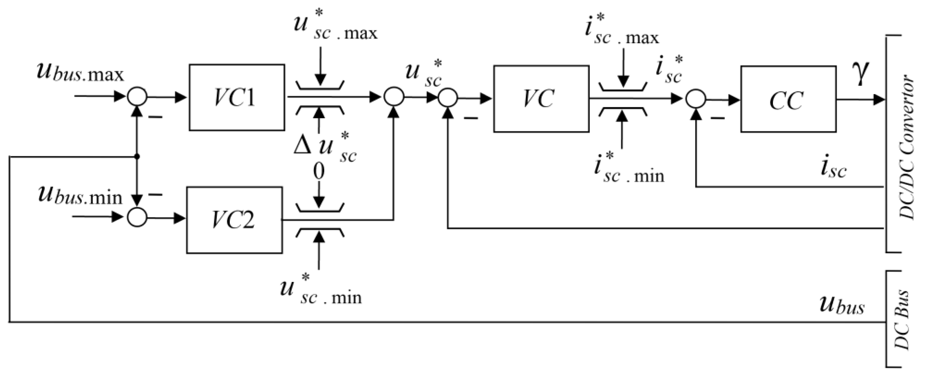
With a three-circuit version of the ACS, a supercapacitor voltage circuit is introduced between the supercapacitor current and DC bus voltage circuits. This is the most versatile version of the ACS structure of an auxiliary power source based on supercapacitors, which makes it possible to implement both basic and additional tasks. The latter includes ensuring the operation of the electric drive in the event of a voltage failure of the main energy source (ride-through mode).
Figure 21 shows the control circuit for the auxiliary power source [81,82]. There is an internal current controller CC and three external voltage controllers, such as a supercapacitor voltage controller (VC) and two DC bus voltage controllers (VC1 and VC2). The internal current controller (CC) regulates the ultracapacitor current isc. The intermediate controller (VC) regulates the voltage of the supercapacitors usc. This controller generates the reference current of the isc* supercapacitors. The DC bus voltage ubus is controlled by two external voltage controllers (VC1 and VC2). VC1 regulates the DC bus voltage when the drive is operating in brake and supercapacitor modes, and VC2 regulates the DC bus voltage when the system is in the ride-through mode. The reference voltage usc* of the supercapacitors is created as the sum of the signals from the outputs of the VC1 and VC2 controllers.
The control algorithm is described in [81,82], taking into account three operating modes that are important from the point of view of control:
- Mains power mode;
- Braking and driving modes from the supercapacitors;
- Ride-through mode.
The control tasks in such a system are as follows. The first task is to stabilise the DC bus voltage. The reference voltage is the maximum voltage ubus.max* = ubus.max when the drive is running in deceleration mode (as well as in energy recovery mode) and the minimum voltage ubus.min* = ubus.min when the mains are interrupted. The second control task is to regulate the state of charge of the supercapacitors depending on the application conditions.
As a result of the synthesis, classical proportional-plus-integral voltage controllers were obtained. The proportional and integral gains of the supercapacitor voltage controller are calculated with the binomial criterion (z = 1), and the DC bus voltage controller with the Butterworth criterion (z = 0.707), where z is the attenuation factor. The structure of the current controller is not presented in [81,82].
Ref. [86] carried out mathematical modelling of a three-loop control system built according to the principles of cascade control with the anticipation of disturbances. The internal current circuit isc of the supercapacitors is subordinated to the voltage circuit usc of the supercapacitors. In turn, the voltage circuit of the supercapacitors is subordinated to the voltage circuit ubus of the DC bus. To prevent disturbances, which increase the speed of the control system, compensating signals are introduced.
To suppress high-frequency noise, low-pass filters are installed in the reference and feedback channels of the isc current controller. The current controller has a structure similar to that of the controller in a single-loop automatic control system described in [84]. The supercapacitor voltage controller is proportional, while the DC bus voltage controller is integral. Synthesis of controllers for a three-loop automatic control system was carried out according to a standard method for synthesizing controllers of one-dimensional systems of subordinate control with the tuning of the loops to a modular (technical) optimum [94]. In this case, all circuits have a standard response to a typical stepwise reference signal.
This control system provides for the limitation of controlled variables and a certain charge sequence for the DC link capacitor of the frequency converter and the supercapacitors of the energy storage.
4.4. Discussion
The most common options for automatic control systems for supercapacitor energy storage devices are single-loop and double-loop control systems. They allow for solving the problems of stabilising the DC bus voltage and maintaining the current and voltage within the specified limits when charging/discharging supercapacitors.
A disadvantage of single-loop automatic control systems is the need to calculate the reference current setting for supercapacitors, at which an error may be introduced depending on the assumptions made. An alternative solution is to use an external current DC/DC converter as a controlled variable. However, there are few publications on this variant.
Another disadvantage of a single-loop automatic control system is that it is difficult to limit the controlled variables. In the works cited, this issue is not adequately covered.
Double-circuit automatic control systems are free from the disadvantages of single-circuit control systems. They are relatively simple and provide acceptable process quality performance in a static mode and over time.
Three-circuit automatic control systems are less common. However, with an appropriate structure, they allow for solving a wider range of problems with a qualitative limitation of the controlled variables. Their disadvantage is the complexity of the control algorithms and the complexity of the settings.
A key objective in the development of automatic control systems for supercapacitor energy storage is to ensure the desired quality indicators of control systems. In this regard, it should be noted that at present there is no generally accepted approach to the synthesis of controllers and the choice of criteria for setting up automatic control systems for supercapacitor energy storage devices. The use of different approaches to the synthesis of controllers and the choice of setting criteria is evidence of this. The reviewed papers reflect the issues of using different types of controllers: proportional and proportional-integral, polynomial, relay, sliding mode, fuzzy logic, and controllers with prediction and adaptation algorithms.
In conclusion, in this review of ACS for energy storage devices, the emphasis is on the analysis of works, the results of which are of practical importance in the modern development of technical means for implementing control algorithms. The review does not contain works devoted to methods for optimising the modes of supercapacitor energy storage devices using, for example, genetic algorithms and artificial neural networks [60].
5. Conclusions
This article presents a comprehensive overview of the use of supercapacitor energy storage systems in adjustable AC drives for various purposes with an emphasis on the implementation of engineering solutions based on state-of-the-art technical aids.
The topologies of the power section of combined power supplies for transport and industrial electric drives are given.
Focus is placed on conventional decisions taken in the implementation of the power part. The effect achieved when supercapacitor energy storage systems are used in controlled electric drives is recorded.
The topologies of reversible DC/DC converters for supercapacitor energy storage devices are considered with a comparative assessment of their advantages and disadvantages, as well as their areas of application. To evaluate DC/DC converters, both private (power losses, ripples in currents, etc.) and generalised (fail-safety, electromagnetic compatibility, etc.) quality indicators are involved.
A review of the structures of ACS for supercapacitor energy storage devices is carried out. The composition and principles of regulation of variables, the types of controllers used, and the criteria for setting control systems are identified.
This review made it possible to identify typical trends and problems. Of the circuit designs for DC/DC up/down converters, the most widely used are the typical topology and multiphase interleaved converters. For industrial electric drives with three-phase motors, there is a tendency to use three-phase DC/DC converters in order to unify the power section. The problem here is the possible phase current imbalance.
In the field of ACS, there are many options, which indicates the absence of a model solution. Despite the use of both single-circuit and multi-circuit ACS, dual-circuit control systems are preferable. With the comparative complexity of the structure of double-circuit ACS, they more effectively solve key control objectives, such as stabilising the DC bus voltage and limiting the current and voltage of the supercapacitor module during charge/discharge.
When analysing problems related to synthesising controllers and choosing setting criteria, various approaches were identified. Despite the complexity of the supercapacitor energy storage as an object of control, in most cases, conventional proportional-plus-integral controllers are used with the damping factor adjusted to the Butterworth filter. In some works, the synthesis of controllers is of a heuristic nature. There are virtually no studies on identifying the parameters of the power section of supercapacitor energy storage devices, automatic controller settings, and digital control features.
This review can be useful in such applications as the development of hybrid power supplies for controlled electric drives in transport systems and general industrial mechanisms. The review can also be used in teaching and learning activities to train specialists in a corresponding field.
Author Contributions
Conceptualization, P.I.; methodology, P.V.; investigation, P.V. and P.I.; writing—original draft preparation, P.V.; writing—review and editing, P.V. and P.I.; supervision, P.I.; project administration, P.I.; funding acquisition, P.I. All authors have read and agreed to the published version of the manuscript.
Funding
The study was supported by a grant from the Russian Science Foundation N° 22-29-01305, https://rscf.ru/en/project/22-29-01305/ (accessed on 4 April 2022).
Data Availability Statement
No data available.
Conflicts of Interest
The authors declare no conflict of interest.
References
- Denshchikov, K.K. Combined power plants based on supercapacitors. In Proceedings of the Conference of the JIHT RAS “Results of fundamental research in the field of energy and their practical significance”, Moscow, Russian, 17–24 August 2008. [Google Scholar]
- Arnet, B.J. A Contribution to the Design and Control of Electric Vehicle Drives; (No. THESIS); EPFL: Lausanne, Switzerland, 1998. [Google Scholar]
- Ivanov, A.M.; Gerasimov, A.F. Molecular energy storage devices based on a double electric layer. Electricity 1991, 8, 16–19. [Google Scholar]
- Ehsani, M.; Gao, Y.; Emadi, A. Modern electric hybrid electric and fuel cell vehicles: Fundamentals. In Theory and Design; CRC Press: Boca Raton, FL, USA, 2010. [Google Scholar]
- Chan, C.C.; Wong, Y.S. Electric vehicles charge forward. IEEE Power Energy Mag. 2004, 2, 24–33. [Google Scholar] [CrossRef]
- United States Environmental Protection Agency EPA. Sources of Green-House Gas Emissions. Available online: https://www.epa.gov/ghgemissions/sources-greenhouse-gas-emissions (accessed on 28 December 2022).
- Kumar, K.A.R.; Sreedevi, M.L.; Mineeshma, G.R.; Chacko, R.V.; Amal, S. Hybrid energy storage system interface for electric vehicles. In Proceedings of the 2020 IEEE International Conference on Power Electronics, Smart Grid and Renewable Energy (PESGRE2020), Cochin, India, 2–4 January 2020; pp. 1–6. [Google Scholar] [CrossRef]
- Van Mierlo, J.; Timmermans, J.M.; Maggetto, G.; Van den Bossche, P.; Meyer, S.; Hecq, W.; Verlaak, J. Environmental rating of vehicles with different alternative fuels and drive trains: A comparison of two approaches. Transp. Res. Part D Transp. Environ. 2004, 9, 387–399. [Google Scholar] [CrossRef]
- Van Mierlo, J.; Favrel, V.; Meyer, S.; Hecq, W. How to Define Clean Vehicles? Environmental Impact Rating of Vehicles. Int. J. Automot. Technol. 2004, 4, 11. [Google Scholar]
- Korotkova, S.D.; Matyash, E.I. Environmental friendliness of public electric transport—Reality or myth? Sci. Today Glob. Chall. Dev. Mech. 2018, 42, Page range. [Google Scholar]
- Bobba, P.B.; Rajagopal, K.R. Modeling and analysis of hybrid energy storage systems used in electric vehicles. In Proceedings of the 2012 IEEE International Conference on Power Electronics, Drives and Energy Systems (PEDES), Bengaluru, India, 16–19 December 2012; pp. 1–6. [Google Scholar] [CrossRef]
- Emadi, A.; Rajashekara, K.; Williamson, S.S.; Lukic, S.M. Topological overview of hybrid electric and fuel cell vehicular power system architectures and configurations. IEEE Trans. Veh. Technol. 2005, 54, 763–770. [Google Scholar] [CrossRef]
- Cao, J.; Emadi, A. A new battery/ultracapacitor hybrid energy storage system for electric, hybrid, and plug-in hybrid electric vehicles. IEEE Trans. Power Electron. 2011, 27, 122–132. [Google Scholar] [CrossRef]
- Yu, H.; Cui, S.; Wang, T. Simulation and performance analysis on an energy storage system for hybrid electric vehicle using ultracapacitor. In Proceedings of the 2008 IEEE Vehicle Power and Propulsion Conference, Harbin, China, 3–5 September 2008; pp. 1–5. [Google Scholar] [CrossRef]
- Xu, W.; Zhu, J.; Guo, Y.; Li, Y.; Wang, Y.; Wang, S. Performance analysis of electric machine drives for plug-in hybrid electric vehicles. In Proceedings of the 2009 International Conference on Applied Superconductivity and Electromagnetic Devices, Chengdu, China, 25–27 September 2009; pp. 60–63. [Google Scholar] [CrossRef] [Green Version]
- Yoo, H.; Sul, S.K.; Park, Y.; Jeong, J. System integration and power-flow management for a series hybrid electric vehicle using supercapacitors and batteries. IEEE Trans. Ind. Appl. 2008, 44, 108–114. [Google Scholar] [CrossRef]
- Cui, S.-M.; Tian, D.-W.; Zhang, Q.-F. Study of hybrid energy control strategy for hybrid electric drive system in all electric combat vehicles. In Proceedings of the 2008 IEEE Vehicle Power and Propulsion Conference, Harbin, China, 3–5 September 2008; pp. 1–5. [Google Scholar] [CrossRef]
- Rudolph, C. Hybrid drive system of an industrial truck using a three-phase DC-DC converter feeding ultra-capacitors. In Proceedings of the 2009 13th European Conference on Power Electronics and Applications, Barcelona, Spain, 8–10 September 2009; pp. 1–10. [Google Scholar]
- Tani, A.; Camara, M.B.; Dakyo, B. Energy management based on frequency approach for hybrid electric vehicle applications: Fuel-cell/lithium-battery and ultracapacitors. IEEE Trans. Veh. Technol. 2012, 61, 3375–3386. [Google Scholar] [CrossRef]
- Huang, X.; Tosiyoki, H.; Yoichi, H. System design and converter control for super capacitor and battery hybrid energy system of compact electric vehicles. In Proceedings of the 2014 16th European Conference on Power Electronics and Applications, Lappeenranta, Finland, 26–28 August 2014; pp. 1–10. [Google Scholar] [CrossRef]
- Liu, X.; Zhang, Q.; Zhu, C. Design of battery and ultracapacitor multiple energy storage in hybrid electric vehicle. In Proceedings of the 2009 IEEE Vehicle Power and Propulsion Conference, Dearborn, MI, USA, 7–11 September 2009; pp. 1395–1398. [Google Scholar] [CrossRef]
- Lopez, M.; Perez, M.A.; Kouro, S. Current control of interleaved dc-dc converter in continuous and discontinuous mode. In Proceedings of the 2018 IEEE International Conference on Electrical Systems for Aircraft, Railway, Ship Propulsion and Road Vehicles & International Transportation Electrification Conference (ESARS-ITEC), Nottingham, UK, 7–9 November 2018; pp. 1–6. [Google Scholar] [CrossRef]
- Tani, A.; Camara, M.B.; Dakyo, B.; Azzouz, Y. DC/DC and DC/AC converters control for hybrid electric vehicles energy management-ultracapacitors and fuel cell. IEEE Trans. Ind. Inform. 2012, 9, 686–696. [Google Scholar] [CrossRef]
- Khan, M.S.; Ahmad, I.; Armaghan, H.; Ali, N. Backstepping sliding mode control of FC-UC based hybrid electric vehicle. IEEE Access 2018, 6, 77202–77211. [Google Scholar] [CrossRef]
- Becherif, M.; Ayad, M.Y.; Miraoui, A. Modeling and passivity-based control of hybrid sources: Fuel cell and supercapacitors. In Proceedings of the Conference Record of the 2006 IEEE Industry Applications Conference Forty-First IAS Annual Meeting, Tampa, FL, USA, 8–12 October 2006; Volume 3, pp. 1134–1139. [Google Scholar] [CrossRef]
- Ayad, M.Y.; Becherif, M.; Djerdir, A.; Miraoui, A. Sliding mode control of DC bus voltage of a hybrid sources using fuel cell and supercapacitors for traction system. In Proceedings of the 2007 IEEE International Symposium on Industrial Electronics, Vigo, Spain, 4–7 June 2007; pp. 383–388. [Google Scholar] [CrossRef]
- Camara, M.B.; Gualous, H.; Gustin, F.; Berthon, A. Design and new control of DC/DC converters to share energy between supercapacitors and batteries in hybrid vehicles. IEEE Trans. Veh. Technol. 2008, 57, 2721–2735. [Google Scholar] [CrossRef]
- Liu, X.; Diallo, D.; Marchand, C. Cycle-based design methodology of hybrid electric vehicle powertrain: Application to fuel cell vehicles. In Proceedings of the 2009 IEEE Vehicle Power and Propulsion Conference, Dearborn, MI, USA, 7–11 September 2009; pp. 1853–1857. [Google Scholar] [CrossRef]
- Steiner, M.; Klohr, M.; Pagiela, S. Energy storage system with ultracaps on board of railway vehicles. In Proceedings of the 2007 European conference on power electronics and applications, Aalborg, Denmark, 2–5 September 2007; pp. 1–10. [Google Scholar] [CrossRef]
- Steiner, M.; Scholten, J. Energy storage on board of DC fed railway vehicles PESC 2004 conference in Aachen, Germany. In Proceedings of the 2004 IEEE 35th Annual Power Electronics Specialists Conference (IEEE Cat. No. 04CH37551), Aachen, Germany, 20–25 June 2004; Volume 1, pp. 666–671. [Google Scholar] [CrossRef]
- Iannuzzi, D.; Tricoli, P. Metro trains equipped onboard with supercapacitors: A control technique for energy saving. In Proceedings of the SPEEDAM 2010, Pisa, Italy, 14–16 June 2010; pp. 750–756. [Google Scholar] [CrossRef] [Green Version]
- Steiner, M.; Scholten, J. Energy storage on board of railway vehicles. In Proceedings of the 2005 European Conference on Power Electronics and Applications, Dresden, Germany, 11–14 September 2005. [Google Scholar] [CrossRef]
- Barrero, R.; Tackoen, X.; Van Mierlo, J. Improving energy efficiency in public transport: Stationary supercapacitor based Energy Storage Systems for a metro network. In Proceedings of the 2008 IEEE Vehicle Power and Propulsion Conference, Harbin, China, 3–5 September 2008; pp. 1–8. [Google Scholar] [CrossRef]
- Mir, L.; Etxeberria-Otadui, I.; de Arenaza, I.P.; Sarasola, I.; Nieva, T. A supercapacitor based light rail vehicle: System design and operations modes. In Proceedings of the 2009 IEEE Energy Conversion Congress and Exposition, San Jose, CA, USA, 20–24 September 2009; pp. 1632–1639. [Google Scholar] [CrossRef]
- Grbovic, P.J.; Delarue, P.; Le Moigne, P.; Bartholomeus, P. A three-terminal ultracapacitor-based energy storage and PFC device for regenerative controlled electric drives. IEEE Trans. Ind. Electron. 2011, 59, 301–316. [Google Scholar] [CrossRef]
- Bellache, K.; Camara, M.B.; Dakyo, B. Transient power control for diesel-generator assistance in electric boat applications using supercapacitors and batteries. IEEE J. Emerg. Sel. Top. Power Electron. 2017, 6, 416–428. [Google Scholar] [CrossRef]
- Bolonne, S.R.; Chandima, D.P. Sizing an energy system for hybrid li-ion battery-supercapacitor RTG cranes based on state machine energy controller. IEEE Access 2019, 7, 71209–71220. [Google Scholar] [CrossRef]
- Grbovic, P.J.; Delarue, P.; Le Moigne, P.; Bartholomeus, P. The ultracapacitor-based regenerative controlled electric drives with power-smoothing capability. IEEE Trans. Ind. Electron. 2012, 59, 4511–4522. [Google Scholar] [CrossRef]
- Von Jouanne, A.; Enjeti, P.N.; Banerjee, B. Assessment of ride-through alternatives for adjustable-speed drives. IEEE Trans. Ind. Appl. 1999, 35, 908–916. [Google Scholar] [CrossRef]
- Yang, Y.C.; Chang, W.M. Impacts of electric rubber-tired gantries on green port performance. Res. Transp. Bus. Manag. 2013, 8, 67–76. [Google Scholar] [CrossRef]
- Kim, S.M.; Sul, S.K. Control of rubber tyred gantry crane with energy storage based on supercapacitor bank. IEEE Trans. Power Electron. 2006, 21, 1420–1427. [Google Scholar] [CrossRef]
- Kermani, M.; Parise, G.; Chavdarian, B.; Martirano, L. Ultracapacitors for port crane applications: Sizing and techno-economic analysis. Energies 2020, 13, 2091. [Google Scholar] [CrossRef]
- Luque, A.; Harrison, I.; Pietrosanti, S.; Alasali, F.M.M.; Holderbaum, W.; Mayer, R.M.; Becerra, V.M. Energy reduction on eRTG. In Proceedings of the 2016 IEEE 16th International Conference on Environment and Electrical Engineering (EEEIC), Florence, Italy, 7–10 June 2016; pp. 1–6. [Google Scholar] [CrossRef]
- Kermani, M.; Shirdare, E.; Parise, G.; Bongiorno, M.; Martirano, L. A Comprehensive Techno-economic Solution for Demand Control in Ports: Energy Storage Systems Integration. IEEE Trans. Ind. Appl. 2022, 58, 1592–1601. [Google Scholar] [CrossRef]
- Iannuzzi, D.; Piegari, L.; Tricoli, P. Use of supercapacitors for energy saving in overhead travelling crane drives. In Proceedings of the 2009 International Conference on Clean Electrical Power, Capri, Italy, 9–11 June 2009; pp. 562–568. [Google Scholar] [CrossRef]
- Di Napoli, A.; Ndokaj, A. Ultracapacitor storage for a 50t capacity gantry crane. In Proceedings of the 2012 XXth International Conference on Electrical Machines, Marseille, France, 2–5 September 2012; pp. 2014–2018. [Google Scholar] [CrossRef]
- Kermani, M.; Parise, G.; Martirano, L.; Parise, L.; Chavdarian, B. Utilization of Regenerative Energy by Ultracapacitor Sizing for Peak Shaving in STS Crane. In Proceedings of the 2019 IEEE International Conference on Environment and Electrical Engineering and 2019 IEEE Industrial and Commercial Power Systems Europe (EEEIC/I&CPS Europe), Genova, Italy, 11–14 June 2019; pp. 1–5. [Google Scholar] [CrossRef]
- Pasquali, M.; Tricoli, P.; Villante, C. Testing methodologies of supercapacitors for load-leveling purposes in industrial applications. In Proceedings of the 2011 International Conference on Clean Electrical Power (ICCEP), Ischia, Italy, 14–16 June 2011; pp. 395–399. [Google Scholar] [CrossRef]
- Rufer, A.; Barrade, P. A supercapacitor-based energy-storage system for elevators with soft commutated interface. IEEE Trans. Ind. Appl. 2002, 38, 1151–1159. [Google Scholar] [CrossRef]
- Shreelakshmi, M.P.; Agarwal, V. An energy efficient and environment friendly elevator system using ultracapacitor and fuel cell with power factor correction. In Proceedings of the 2013 IEEE ECCE Asia Downunder, Melbourne, VIC, Australia, 3–6 June 2013; pp. 721–727. [Google Scholar] [CrossRef]
- Kubade, P.; Umathe, S.K. Enhancing an elevator efficiency by using supercapacitor. In Proceedings of the 2017 Third International Conference on Advances in Electrical, Electronics, Information, Communication and Bio-Informatics (AEEICB), Chennai, India, 27–28 February 2017; pp. 502–505. [Google Scholar] [CrossRef]
- Plotnikov, I.; Braslavsky, I.; Yeltsin, B.N.; Ishmatov, Z. About using the frequency-controlled electric drives with supercapacitors in the hoisting applications. In Proceedings of the 2015 International Siberian Conference on Control and Communications (SIBCON), Omsk, Russia, 21–23 May 2015; pp. 1–9. [Google Scholar] [CrossRef]
- Li, Z.; Ruan, Y. A novel energy saving control system for elevator based on supercapacitor bank using fuzzy logic. In Proceedings of the 2008 International Conference on Electrical Machines and Systems, Wuhan, China, 17–20 October 2008; pp. 2717–2722. [Google Scholar]
- Kim, J.; Han, Z.; Huang, P.; O’Donnell, D.; Kar, N.C. Comparative analysis of the utilization of supercapacitor versus grid-tie inverter regenerative braking methods for elevator systems. In Proceedings of the IECON 2019-45th Annual Conference of the IEEE Industrial Electronics Society, Lisbon, Portugal, 14–17 October 2019; Volume 1, pp. 2535–2540. [Google Scholar] [CrossRef]
- Tominaga, S.; Suga, I.; Araki, H.; Ikejima, H.; Kusuma, M.; Kobayashi, K. Development of energy-saving elevator using regenerated power storage system. In Proceedings of the Power Conversion Conference-Osaka 2002 (Cat. No. 02TH8579), Osaka, Japan, 2–5 April 2002; Volume 2, pp. 890–895. [Google Scholar] [CrossRef]
- Jabbour, N.; Mademlis, C.; Kioskeridis, I. Improved performance in a supercapacitor-based energy storage control system with bidirectional DC-DC converter for elevator motor drives. In Proceedings of the 7th IET International Conference on Power Electronics, Machines and Drives (PEMD 2014), Manchester, UK, 8–10 April 2014; pp. 1–6. [Google Scholar] [CrossRef] [Green Version]
- Jabbour, N.; Mademlis, C. Supercapacitor-based energy recovery system with improved power control and energy management for elevator applications. IEEE Trans. Power Electron. 2017, 32, 9389–9399. [Google Scholar] [CrossRef]
- Kulkarni, A.B.; Nguyen, H.; Gaudet, E.W. A comparative evaluation of fine regenerative and nonregenerative vector controlled drives for AC gearless elevators. In Proceedings of the Conference Record of the 2000 IEEE Industry Applications Conference. Thirty-Fifth IAS Annual Meeting and World Conference on Industrial Applications of Electrical Energy (Cat. No. 00CH37129), Rome, Italy, 8–12 October 2000; Volume 3, pp. 1431–1437. [Google Scholar] [CrossRef]
- Kafalis, K.; Karlis, A.D. Supercapacitors based energy saving mode of electromechanical elevator’s operation. In Proceedings of the 2016 XXII International Conference on Electrical Machines (ICEM), Lausanne, Switzerland, 4–7 September 2016; pp. 1208–1214. [Google Scholar] [CrossRef]
- Chakraborty, S.; Vu, H.N.; Hasan, M.M.; Tran, D.D.; Baghdadi, M.E.; Hegazy, O. DC-DC converter topologies for electric vehicles, plug-in hybrid electric vehicles and fast charging stations: State of the art and future trends. Energies 2019, 12, 1569. [Google Scholar] [CrossRef] [Green Version]
- De Almeida, A.T.; Ferreira, F.J.; Both, D. Technical and economical considerations in the application of variable-speed drives with electric motor systems. IEEE Trans. Ind. Appl. 2005, 41, 188–199. [Google Scholar] [CrossRef]
- Grbović, P.J.; Delarue, P.; Le Moigne, P. Interface converters for ultra-capacitor applications in power conversion systems. In Proceedings of the 2012 15th International Power Electronics and Motion Control Conference (EPE/PEMC), Novi Sad, Serbia, 4–6 September 2012; p. LS7d–1. [Google Scholar] [CrossRef]
- Lemian, D.; Bode, F. Battery-supercapacitor energy storage systems for electrical vehicles: A review. Energies 2022, 15, 5683. [Google Scholar] [CrossRef]
- Pan, L.; Zhang, C. An integrated multifunctional bidirectional AC/DC and DC/DC converter for electric vehicles applications. Energies 2016, 9, 493. [Google Scholar] [CrossRef] [Green Version]
- Grbović, P.J.; Delarue, P.; Le Moigne, P.; Bartholomeus, P. A bidirectional three-level DC–DC converter for the ultracapacitor applications. IEEE Trans. Ind. Electron. 2009, 57, 3415–3430. [Google Scholar] [CrossRef]
- Camara, M.B.; Gualous, H.; Dakyo, B.; Nichita, C.; Makany, P. Buck-Boost converters design for Ultracapacitors and lithium Battery mixing in Hybrid Vehicle Applications. In Proceedings of the 2010 IEEE Vehicle Power and Propulsion Conference, Lille, France, 1–3 September 2010; pp. 1–6. [Google Scholar] [CrossRef]
- Bausière, R.; Labrique, F.; Séguier, G. Power Electronic Converters—DC-DC Conversion; Springer: Berlin, Germany, 1993; 434p. [Google Scholar] [CrossRef]
- Choi, B. Comparative study on paralleling schemes of converter modules for distributed power applications. IEEE Trans. Ind. Electron. 1998, 45, 194–199. [Google Scholar] [CrossRef]
- Zumel, P.; Garcia, O.; Cobos, J.A.; Uceda, J. Magnetic integration for interleaved converters. In Proceedings of the Eighteenth Annual IEEE Appl. Power Electron. Conf. Expo. 2003, 2, 1143–1149. [Google Scholar] [CrossRef]
- Silva, D.F.; Pomilio, J.A.; Villalva, M.G. Hybrid energy storage system and control strategy for an electric urban bus. In Proceedings of the 2018 13th IEEE International Conference on Industry Applications (INDUSCON), Sao Paulo, Brazil, 12–14 November 2018; pp. 453–458. [Google Scholar] [CrossRef]
- Ciccarelli, F.; Del Pizzo, A.; Iannuzzi, D. Improvement of energy efficiency in light railway vehicles based on power management control of wayside lithium-ion capacitor storage. IEEE Trans. Power Electron. 2013, 29, 275–286. [Google Scholar] [CrossRef]
- Amjadi, Z.; Williamson, S.S. Novel control strategy design for multiple hybrid electric vehicle energy storage systems. In Proceedings of the 2009 Twenty-Fourth Annual IEEE Applied Power Electronics Conference and Exposition, Washington, DC, USA, 15–19 February 2009; pp. 597–602. [Google Scholar] [CrossRef]
- Abdel-baqi, O.; Nasiri, A.; Miller, P. Dynamic performance improvement and peak power limiting using ultracapacitor storage system for hydraulic mining shovels. IEEE Trans. Ind. Electron. 2014, 62, 3173–3181. [Google Scholar] [CrossRef]
- Wang, J.; Peng, R.; Cai, C.; Yu, H.; Chen, M.; Liu, Y.; Wu, K.; Tang, S.; Wei, H.; Chen, J. An efficiency optimization control method for three-phase interleaved dc-dc converter. In Proceedings of the 2021 3rd Asia Energy and Electrical Engineering Symposium (AEEES), Chengdu, China, 26–29 March 2021; pp. 285–289. [Google Scholar] [CrossRef]
- Ebisumoto, D.; Kimura, S.; Nanamori, K.; Noah, M.; Ishihara, M.; Imaoka, J.; Yamamoto, M. Analytical investigation of interleaved DC-DC converter using closed-coupled inductor with phase drive control. In Proceedings of the 2017 IEEE International Telecommunications Energy Conference (INTELEC), Broadbeach, QLD, Australia, 22–26 October 2017; pp. 526–529. [Google Scholar] [CrossRef]
- Nandankar, P.; Rothe, J.P. Design and implementation of efficient three-phase interleaved DC-DC converter. In Proceedings of the International Conference & Workshop on Electronics & Telecommunication Engineering (ICWET 2016), Chennai, India, 3–5 March 2016; pp. 1–7. [Google Scholar] [CrossRef]
- Zuber, D. MittelFrequente Resonante DC-DC Wandler Fur Traktions Anwendungen. Ph.D. Thesis, ETHZ, Zurich, Switzerland, 2001. [Google Scholar] [CrossRef]
- Jeong, J.U.; Lee, H.D.; Kim, C.S.; Choi, H.S.; Cho, B.H. A development of an energy storage system for hybrid electric vehicles using supercapacitor. In Proceedings of the The 19th International Battery, Hybrid and Fuel Cell Electric Vehicle Symposium & Exhibition, Busan, Korea, 19–23 October 2022; pp. 1379–1389. [Google Scholar]
- Inoue, S.; Akagi, H. A bidirectional DC–DC converter for an energy storage system with galvanic isolation. IEEE Trans. Power Electron. 2007, 22, 2299–2306. [Google Scholar] [CrossRef]
- Attaianese, C.; Nardi, V.; Tomasso, G. High performances supercapacitor recovery system for industrial drive applications. In Proceedings of the Nineteenth Annual IEEE Applied Power Electronics Conference and Exposition, APEC’04, Anaheim, CA, USA, 22–26 February 2004; Volume 3, pp. 1635–1641. [Google Scholar] [CrossRef]
- Grbovic, P.J.; Delarue, P.; Le Moigne, P.; Bartholomeus, P. Modeling and control of the ultracapacitor-based regenerative controlled electric drives. IEEE Trans. Ind. Electron. 2010, 58, 3471–3484. [Google Scholar] [CrossRef]
- Grbović, P.J.; Delarue, P.; Le Moigne, P.; Bartholomeus, P. The ultracapacitor-based controlled electric drives with braking and ride-through capability: Overview and analysis. IEEE Trans. Ind. Electron. 2010, 58, 925–936. [Google Scholar] [CrossRef]
- Timmermans, J.M.; Zadora, P.; Cheng, Y.; Van Mierlo, J.; Lataire, P. Modelling and design of super capacitors as peak power unit for hybrid electric vehicles. In Proceedings of the 2005 IEEE Vehicle Power and Propulsion Conference, Chicago, IL, USA, 7 September 2005. [Google Scholar] [CrossRef]
- Polyakov, V.; Plotnikov, I.; Postniko, N. Single-Loop Control System for Energy Storage Device in the Frequency-Controlled Electric Drive. In Proceedings of the 2018 X International Conference on Electrical Power Drive Systems (ICEPDS), Novocherkassk, Russia, 3–6 October 2018; pp. 1–5. [Google Scholar] [CrossRef]
- Thounthong, P.; Raël, S.; Davat, B. Control strategy of fuel cell and supercapacitors association for a distributed generation system. IEEE Trans. Ind. Electron. 2007, 54, 3225–3233. [Google Scholar] [CrossRef]
- Polyakov, V.; Plotnikov, I.; Postnikov, N. Comparative analysis of DC/DC converter control systems for variable-frequency drives with supercapacitors. In Proceedings of the 2019 International Ural Conference on Electrical Power Engineering (UralCon), Chelyabinsk, Russia, 1–3 October 2019; pp. 317–323. [Google Scholar] [CrossRef]
- Kloetzl, J.; Gerling, D. An interleaved buck-boost-converter combined with a supercapacitor-storage for the stabilization of automotive power nets. In Proceedings of the 2011 IEEE Vehicle Power and Propulsion Conference, Chicago, IL, USA, 6–9 September 2011; pp. 1–6. [Google Scholar] [CrossRef]
- Iannuzzi, D.; Lauria, D. A new supercapacitor design methodology for light transportation systems saving. In Energy Management Systems; IntechOpen: Rijeka, Croatia, 2011; pp. 183–198. [Google Scholar] [CrossRef] [Green Version]
- Zhang, X.; Yin, C.; Jiang, Y.; Pan, S. A realtime apf method for battery ripple current reduction in hess-based electric vehicles. In Proceedings of the 2014 IEEE Vehicle Power and Propulsion Conference (VPPC), Coimbra, Portugal, 27–30 October 2014; pp. 1–5. [Google Scholar] [CrossRef]
- Russo, A.; Cavallo, A. Supercapacitor stability and control for More Electric Aircraft application. In Proceedings of the 2020 European Control Conference (ECC), St. Petersburg, Russia, 12–15 May 2020; pp. 1909–1914. [Google Scholar] [CrossRef]
- Lhomme, W.; Delarue, P.; Barrade, P.; Bouscayrol, A.; Rufer, A. Design and control of a supercapacitor storage system for traction applications. In Proceedings of the Fourtieth IAS Annual Meeting. Conference Record of the 2005 Industry Applications Conference, Hong Kong, China, 2–6 October; 2005; Volume 3, pp. 2013–2020. [Google Scholar] [CrossRef]
- Wang, L.; Li, H. Maximum fuel economy-oriented power management design for a fuel cell vehicle using battery and ultracapacitor. IEEE Trans. Ind. Appl. 2010, 46, 1011–1020. [Google Scholar] [CrossRef]
- Arnet, B.J.; Haines, L.P. High power DC-to-DC converter for supercapacitors. In Proceedings of the IEMDC 2001. IEEE International Electric Machines and Drives Conference (Cat. No. 01EX485), Cambridge, MA, USA, 17–20 June 2001; pp. 985–990. [Google Scholar] [CrossRef]
- Schreiner, R.T. Systems of Subordinate Regulation of Electric Drives: Textbook; Publishing house of GOU VPO Ros. state prof.-ped. un: Yekaterinburg, Ruassia, 2008; p. 279. [Google Scholar]
Figure 1.
Combined vehicle system with ICE as the main energy source.

Figure 2.
Combined 4WD vehicle system with ICE/G as main power source.

Figure 3.
Combined vehicle system with ICE/G as main power source.

Figure 4.
Combined truck drive system with ICE/G as main power source.

Figure 5.
Combined vehicle system with a battery as the main power source: (a) first topology; (b) second topology.
Figure 5.
Combined vehicle system with a battery as the main power source: (a) first topology; (b) second topology.

Figure 6.
Combined vehicle system with a controlled battery as the main power source.

Figure 7.
Combined vehicle system with FC as the main power source.

Figure 8.
Combined vehicle system with FC as the main energy source and controllable auxiliary sources B and SC.
Figure 8.
Combined vehicle system with FC as the main energy source and controllable auxiliary sources B and SC.

Figure 9.
Combined traction drive system with DC mains as the main power source.

Figure 10.
A combined crane electric drive system with mains supply as the main energy source.

Figure 11.
A combined lift electric drive system with a power supply network as the main energy source and a backup source FC.
Figure 11.
A combined lift electric drive system with a power supply network as the main energy source and a backup source FC.

Figure 12.
DC-to-DC boost converter chart.

Figure 13.
A boost-down converter with super capacitor module.

Figure 14.
Three-level topology of DC/DC converter.

Figure 15.
Parallel topology DC/DC conversion with single-phase conversion method: (a) option 1; (b) option 2.
Figure 15.
Parallel topology DC/DC conversion with single-phase conversion method: (a) option 1; (b) option 2.

Figure 16.
Topology of a three-phase DC/DC interleaved converter.

Figure 17.
Full bridge resonant DC/DC converter topologies.

Figure 18.
ZVT/ZCS converter topologies.

Figure 19.
Generalised single-circuit ACS of a supercapacitor energy storage.

Figure 20.
Generalised two-circuit ACS of supercapacitor energy storage.

Figure 21.
Three-circuit ACS of a supercapacitor energy storage.

Disclaimer/Publisher’s Note: The statements, opinions and data contained in all publications are solely those of the individual author(s) and contributor(s) and not of MDPI and/or the editor(s). MDPI and/or the editor(s) disclaim responsibility for any injury to people or property resulting from any ideas, methods, instructions or products referred to in the content. |
© 2023 by the authors. Licensee MDPI, Basel, Switzerland. This article is an open access article distributed under the terms and conditions of the Creative Commons Attribution (CC BY) license (https://creativecommons.org/licenses/by/4.0/).
Share and Cite
MDPI and ACS Style
Vladimir, P.; Iurii, P. Supercapacitor Energy Storages in Hybrid Power Supplies for Frequency-Controlled Electric Drives: Review of Topologies and Automatic Control Systems. Energies 2023, 16, 3287. https://doi.org/10.3390/en16073287
AMA Style
Vladimir P, Iurii P. Supercapacitor Energy Storages in Hybrid Power Supplies for Frequency-Controlled Electric Drives: Review of Topologies and Automatic Control Systems. Energies. 2023; 16(7):3287. https://doi.org/10.3390/en16073287
Chicago/Turabian StyleVladimir, Polyakov, and Plotnikov Iurii. 2023. "Supercapacitor Energy Storages in Hybrid Power Supplies for Frequency-Controlled Electric Drives: Review of Topologies and Automatic Control Systems" Energies 16, no. 7: 3287. https://doi.org/10.3390/en16073287
Note that from the first issue of 2016, this journal uses article numbers instead of page numbers. See further details here.