Article

Hydromechanical Impacts of CO2 Storage in Coal Seams of the Upper Silesian Coal Basin (Poland)

1
GFZ German Research Centre for Geosciences, 14473 Potsdam, Germany
2
Geoenvironmental Research Centre, School of Engineering, Cardiff University, Cardiff CF24 3AA, UK
3
Central Mining Institute, 40-166 Katowice, Poland
4
Polska Grupa Górnicza S.A., 40-039 Katowice, Poland
5
University of Potsdam, Institute of Geosciences, 14476 Potsdam, Germany
*
Author to whom correspondence should be addressed.
Energies 2023, 16(7), 3279; https://doi.org/10.3390/en16073279
Submission received: 15 March 2023 / Revised: 24 March 2023 / Accepted: 4 April 2023 / Published: 6 April 2023
(This article belongs to the Special Issue Advances in Carbon Capture, Utilization and Storage (CCUS))

Abstract

:
Deep un-mineable coal deposits are viable reservoirs for permanent and safe storage of carbon dioxide (CO2) due to their ability to adsorb large amounts of CO2 in the microporous coal structure. A reduced amount of CO2 released into the atmosphere contributes in turn to the mitigation of climate change. However, there are a number of geomechanical risks associated with the commercial-scale storage of CO2, such as potential fault or fracture reactivation, microseismic events, cap rock integrity or ground surface uplift. The present study assesses potential site-specific hydromechanical impacts for a coal deposit of the Upper Silesian Coal Basin by means of numerical simulations. For that purpose, a near-field model is developed to simulate the injection and migration of CO2, as well as the coal-CO2 interactions in the vicinity of horizontal wells along with the corresponding changes in permeability and stresses. The resulting effective stress changes are then integrated as boundary condition into a far-field numerical model to study the geomechanical response at site-scale. An extensive scenario analysis is carried out, consisting of 52 simulation runs, whereby the impacts of injection pressures, well arrangement within two target coal seams as well as the effect of different geological uncertainties (e.g., regional stress regime and rock properties) is examined for operational and post-operational scenarios. The injection-induced vertical displacements amount in maximum to 3.59 cm and 1.07 cm directly above the coal seam and at the ground surface, respectively. The results further demonstrate that neither fault slip nor dilation, as a potential consequence of slip, are to be expected during the investigated scenarios. Nevertheless, even if fault integrity is not compromised, dilation tendencies indicate that faults may be hydraulically conductive and could represent local pathways for upward fluid migration. Therefore, the site-specific stress regime has to be determined as accurately as possible by in-situ stress measurements, and also fault properties need to be accounted for an extensive risk assessment. The present study obtained a quantitative understanding of the geomechanical processes taking place at the operational and post-operational states, supporting the assessment and mitigation of environmental risks associated with CO 2 storage in coal seams.

1. Introduction

An essential key technology to reduce the amount of carbon dioxide (CO2) released into the atmosphere and mitigate the effects of climate change is the safe and permanent storage of CO2 in the deep geologic subsurface [1]. Anthropogenic CO2 can be injected in porous formations, e.g., deep saline aquifers, depleted oil and gas reservoirs, but also coal beds. Deep un-mineable coal deposits are viable reservoirs for geological time periods, due to their high adsorption potential and large pore volumes [2], related to their characteristic internal structure [3]. Coal beds are naturally fractured sedimentary rocks, which generally consist of a well-defined fracture network (cleats), separating distinct blocks of the coal matrix, which comprises large amounts of macro- and micropores (Figure 1b). Moreover, coal seams are located in areas that are close to major CO2 emissions sources [4,5], what would reduce costs of CO2 transport from the source to the storage site. Whether there are also economic incentives to use coal seams as storage formations remains a topic of future research, as previous studies have only considered CO2 storage in coal beds in combination with ECBM (Enhanced Coal Bed Methane Recovery) [6,7].
Under subsurface conditions, the injected CO2 is partly present as a free phase and partly immobilised by adsorption to the coal matrix, what causes coal swelling. The adsorption-induced swelling of the coal matrix constricts the fluid flow pathways, leading to a reduction in permeability, and can result in a considerable loss of injectivity in the well bore vicinity [8,9,10]. Coal swelling constitutes a major challenge, as experienced in several demonstration projects related to CO2 injection into coal beds [11,12,13]. Fang et al. [14] developed a dynamic matrix- and fracture-permeability model to simulate the CO2-ECBM process, which takes into account the effects of pressure relief, CO2 pressure injection, matrix shrinkage, and swelling on permeability changes. In general, coal swelling is almost proportional to the amount of CO2 adsorbed in its matrix [3]. The capacity for CO2 storage depends on the coal rank and operational conditions [15], such as temperature, pressure and coal moisture content [16,17]. Using horizontal wells could substantially enlarge the coal-CO2 contact area, and establish a good connection to the cleats as dominant flow pathways [18]. Many numerical simulation studies investigated the potential of using horizontal wells in the context of ECBM [19,20,21,22,23], whereas their field applications are rarely reported [24]. Hence, in order to deliver sustained rates of CO2 injection and overcome the challenge posed by coal swelling, this study investigates a horizontal well configuration.
A number of hydromechanical risks is associated with the storage of CO2, such as fault or fracture reactivation, cap rock integrity and ground surface movement. An injection of CO2 into the geological subsurface always induces a pressure build-up, whereby also small changes in reservoir pressure alter the pre-injection stress state and result in geomechanical effects. Even small pore pressure changes may result in microseismic events due to rock heterogeneities, and represent a risk of generating new fractures, what could in turn affect caprock integrity. Larger changes of the recent stress field may reactive critically stressed faults, which then may act as preferential leakage pathways for a buoyancy-driven migration of CO2 into shallower aquifers. To address these geomechanical risks, numerical models can be used to predict the mechanical response related to an injection of CO2 [25,26,27].
In the present study, the hydromechanical impact of a prospective commercial-scale CO2 storage is assessed for a coal deposit. Therefore, a near-field model is used to simulate the injection and migration of CO2 as well as the coal-CO2 interactions for the vicinity of horizontal wells, along with the corresponding changes in permeability and stress. The resulting effective stress changes are then integrated as a boundary condition into a far-field numerical model to study the geomechanical response at site-scale. The far-field model comprises all relevant lithostratigraphic units as well as the exact geometries of the local fault system. This serves as basis for an extensive scenario analysis investigating the effect of different geological uncertainties (e.g., regional stress regime and rock properties). The main aim of the present work is to obtain a quantitative understanding of the geomechanical processes taking place at the operational and post-operational states to assess and mitigate environmental risks, such as ground surface uplift and a fault reactivation.

2. Materials and Methods

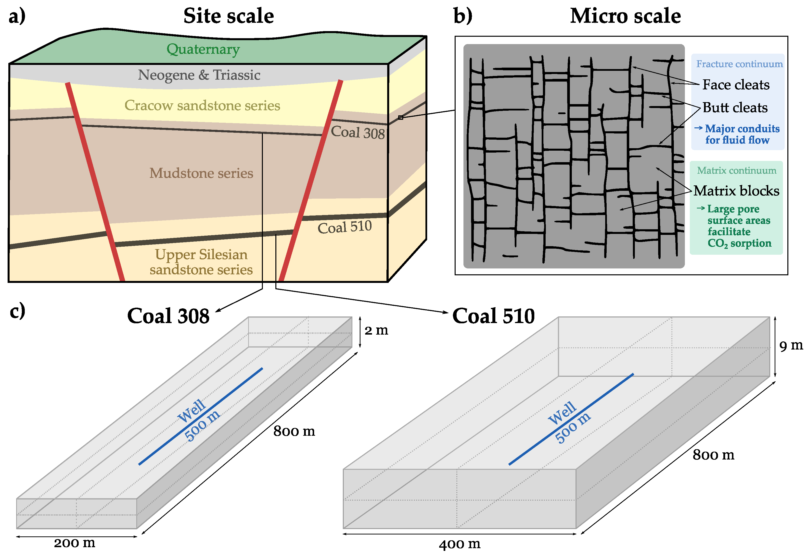
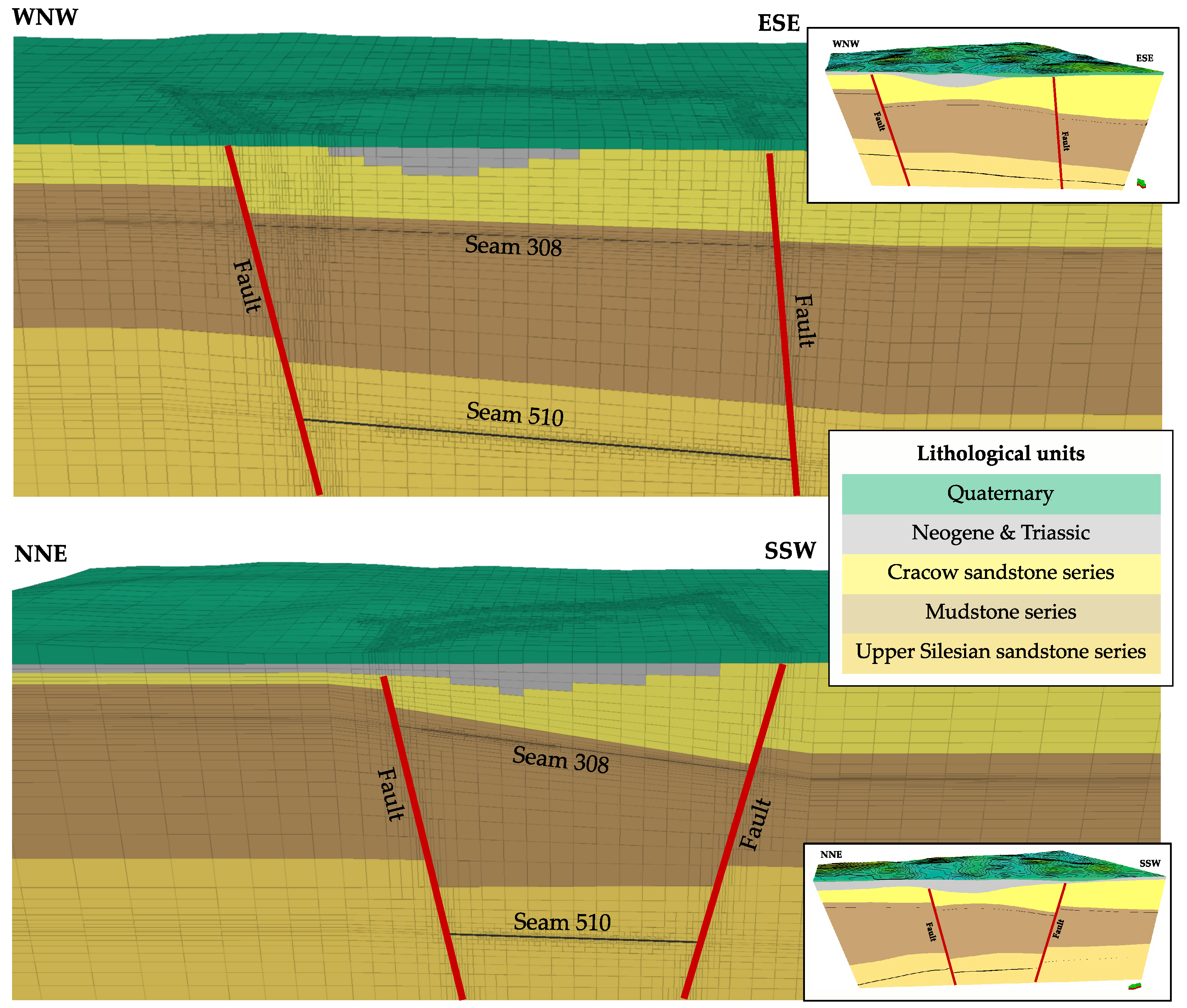
2.1. Geology of the Study Site

The prospective commercial-scale storage site is located in the central part of the Upper Silesian Coal Basin. The lithostratigraphy in the study area includes Quaternary (Pleistocene) and Neogene (Miocene) sediments, lying unconformable on top of Triassic deposits and the Upper Carboniferous. The productive coal-bearing Carboniferous strata consist of the Cracow sandstone series, the Mudstone series as well as the Upper Silesian sandstone series [28].
Two coal seams are found to be suitable for CO2 storage: coal seams 308 and 510 (Figure 1a). Coal seam 308 is situated in the Mudstone series and represents a well studied seam, which has been exploited for decades. It is located at an average depth of 405 m and gently dips towards ESE, whereby its mean thickness is about 2 m. Coal seam 510 is part of the Upper Silesian sandstone series and lies at a considerably greater depth of 1250 m below the ground surface. It gently dips towards SSW and exhibits, with in average 9 m, the highest thickness of all seams in this area [29].
Several steep dipping major faults separate the study area into individual tectonic blocks, whereby each block exhibits a relatively homogeneous internal structure. The tectonic block of interest forms a trench structure, whereby its lateral extent considerably decreases with depth. The dominant strike directions for the four major faults limiting the considered fault block are SW–NE and SE–NW. Moreover, there is a network of minor faults with offsets of up to several meters, which have to be considered for the assessment of fault reactivation and as potential CO2 leakage pathways.

2.2. Near-Field Model Simulating CO2 Injection and Adsorption-Induced Coal Swelling

For the near-field model domain, a coupled hydromechanical model is developed to assess CO2 flow within the target coal seams and coal-CO2 interaction along with the corresponding changes in permeability and stress. Numerical simulations are performed using the parallel finite element-based simulator COMPASS (COde for Modelling PArtially Saturated Soils), which has been developed by Thomas et al. (e.g., [30,31]). The governing equations of flow, deformation and the adsorption/desorption kinetics are included with appropriate couplings to simulate fluid flow through an elastically deformable fractured rock.
The characteristic internal structure of coal is conceptualised using a dual continuum model. The cleat network constitutes the primary flow path, whereas the coal matrix provides available adsorption sites for CO2 (Figure 1b). The fracture system and porous matrix are treated as distinct continua, and flow interactions between both continua are integrated using mass exchange. The following general assumptions are made: (i) CO2 adsorption occurs in the matrix continuum only, (ii) coal is a dry, homogeneous, isotropic and dual poroelastic medium, (iii) strain is small, (iv) coal is isothermal, and (v) Darcy’s law is applied for gas flow in fractures. The reliability of the proposed model has been extensively evaluated by numerous validation studies. The reader is kindly referred to [18,31,32] for all details on the mathematical model implementation and verification benchmarks. These studies demonstrated that simulated gas transport and coal-CO2 interactions are consistent with the respective experimental results.
Two models are set up for the coal seams 308 and 510 at the study site, whereby model dimensions vary accordingly. For both coal seams, the total model length is 800 m, of which 500 m corresponds to the length of the horizontal well (Figure 1c). The model height relates to the respective average thickness of the coal seams and amounts to 2 m and 9 m for seam 308 and 510, respectively. The model width is based on the anticipated maximal CO2 migration distances, and amounts to 200 m and 400 m for coal seams 308 and 510, respectively. Due to the underlying symmetry, only one quarter of the domain is simulated. The model domain is discretised using tetrahedral elements. A zero-flux boundary for gas flow is applied at the external domain boundaries. For coal deformation, a constant volume condition is applied. It is assumed that there is no CO2 present in the model domain prior to the injection. Figure 2 exhibits the adsorption isotherm and adsorption-induced swelling strain based on van Wageningen et al. [33], which are considered for the numerical simulations. Further model parameters and the corresponding references are listed in Table 1.
Three injection scenarios are simulated for respective coal seam, whereby different constant injection pressures are assigned to the horizontal well. These pressures are related to the hydrostatic pressures at the respective seam depths, assuming that the maximum pressure increase is below the 1.5-fold of the hydrostatic pressure. Consequently, constant injection pressures of 0.5 MPa, 1.0 MPa and 1.5 MPa are assumed for coal seam 308. The scenarios for the deeper coal seam 510 are oriented on the hypothetical hydrostatic pressure increase of the scenarios for seam 308 to maintain comparability between the results. Thus, constant injection pressures of 1.5 MPa, 3.0 MPa and 4.5 MPa used at the horizontal well in coal seam 510. The resulting total amounts of injected CO2 for the respective scenarios are listed in Table 2. The injection operation is simulated for a time period of one year (operational state), afterwards CO2 injection is stopped. To evaluate the effectiveness of long-term storage as well as CO2 migration and the evolution of adsorption-induced coal swelling, the total simulation time is extended to 15 years (post-operational state).

2.3. Far-Field Model Assessing the Commercial-Scale Hydromechanical Impact

A hydromechanical model is implemented by means of the numerical simulator FLAC3D [40], aiming at capturing the geomechanical response and evaluating risks of a prospective CO2 injection at field-scale. The model consists of five individual stratigraphic units and two coal seams, which are simplified using the average dipping angle, azimuth, and mean depth for each geological layer. The thickness of all units varies within the model, except for the coal seams, which have a constant thickness of 2 m and 9 m, respectively (Figure 3).
The local fault system, consisting of four major and five minor faults, is implemented using their entire complex geometry. In order to localise zones of potentially reduced mechanical integrity, and thus potential fluid migration pathways at reactivated fault segments, fault zones are implemented into the hydromechanical model as 67,655 ubiquitous joint elements. Ubiquitous joints resemble weak zones within a geomechanical model, whereby dip angles and directions of faults may be individually assigned to each model element at the fault plane. The faults cut the entire Carboniferous strata, while Neogene, Triassic and Quaternary units remain unaffected. Fault displacements are incorporated to consider the effect of rock property changes along the faults. A linear-elastic constitute law is assigned to all lithological layers in the numerical model, whereas the Mohr–Coulomb failure model is used for the ubiquitous joint elements. Fault properties are assigned with zero cohesion, a friction angle of 20° and a dilation angle of 10° to maintain conservative assumptions but not to underestimate potential shear and tensile failure [41]. The resulting numerical model, with the applied simplifications, accurately captures the characteristic geometry of the lithological units and especially the complex fault system (Figure 4).
The model has an extent of 4000 m × 6000 m and is discretised with a lateral resolution of 200 m. The size of the entire model domain (12,000 m × 18,000 m) corresponds to the three-fold of the area of interest to avoid impacts of the applied mechanical boundary conditions on the simulation results as discussed in [42]. Local grid refinements by a factor of three are applied to the elements in the near-field model domain and fault vicinity to accurately account for local hydromechanical effects (Figure 3). Fixed velocities perpendicular to the model bottom and the lateral boundaries are applied, while the model top is defined to remain unconstrained. The model is discretised by 500,000 elements, with grid element sizes decreasing towards the target coal seams and increasing towards the model boundaries.
In order to analyse potential site-specific hydromechanical impacts of the prospective CO2 storage operation, rock parameter uncertainties as well as the regional stress regime are assessed as geological uncertainties. The effect of mechanical rock properties is investigated in two scenarios: a soft and a stiff one (Table 3). The stiffer parameter for the Carboniferous strata refer to averaged data from the Wieczorek mine [41,43], whereas the soft parameters are derived from average values of a few dozen borehole samples from a local coal deposit [44]. Geomechanical parameters of the Quaternary, Neogene, Triassic and the stiff basement are assumed based on their lithologies. Elastic properties of the two coal seams are assigned according to the near-field model with Young’s moduli of 1.8 GPa [36] and 2.2 GPa [44] for coal seam 308 and 510, respectively. These values are maintained constant, since changing elastic moduli of the coal would result in different simulated effective stress changes within the near-field model, what would require dedicated near-field simulations to incorporate the effect of coal property changes.
Additionally, the effect of the regional stress regime is assessed. For the Upper Silesian Coal Basin in Poland, most of hydraulic fracturing tests and focal mechanism data indicate the predominance of a strike-slip stress regime with a maximum horizontal stress orientation in NW-SE direction and a SHmax azimuth of 167° [45], whereby SHmax was reported to be 1.22 SV. By contrast, the analysis of local focal mechanisms around the local coal deposit indicates a predominant normal faulting regime, whereby the azimuth of the maximum horizontal stress orientation is 79° [44]. Both stress regimes are investigated, whereby the vertical stress gradient results from the gravitational load of the overburden. The equilibrated mechanical state of the numerical model serves as starting data set for the respective scenario analysis.

2.4. Workflow to Couple Near- and Far-Field Simulations

Since so far not one numerical simulator is able to assess the complex processes of mechanics, adsorption and multiphase flow across several spatial scales, numerical simulations are performed at both scales separately. The effects of interactions between fluid flow, stress, and gas adsorption in the near-field domain are then implemented within the far-field model to study hydromechanical effects due to adsorption-induced coal swelling and pore pressure increase.
Therefore, a robust and adaptive coupling workflow is developed, which is able to flexibly transfer data between different simulation programs and model grids. Near-field simulations are performed with the numerical modelling code COMPASS, which employs tetrahedral grids for model discretisation. The hydromechanical far-field model is generated with the geomechanical simulator FLAC3D and uses hexahedral elements. Effective stress changes have been chosen as coupling parameter. Due to fixed displacement boundary conditions in the near-field models, effective stresses considerably increase, mainly due to the high surface stresses resulting from the CO2 adsorption. Thus, transferring and implementing effective stress changes enables to investigate hydromechanical effects of the CO2 storage operation in the far-field.
At first, the FLAC3D mesh of the near-field model domain is refined by a factor of three to accurately transfer the near-field simulation results. A Python-based workflow extracts and calculates effective stress changes for the operational and post-operational time step in the near-field and interpolates them to the refined far-field mesh, where effective stress changes are assigned as internal boundary condition. Thus, results for each near-field injection domain are replicate within the target coal seams for several injection wells in the far-field model.

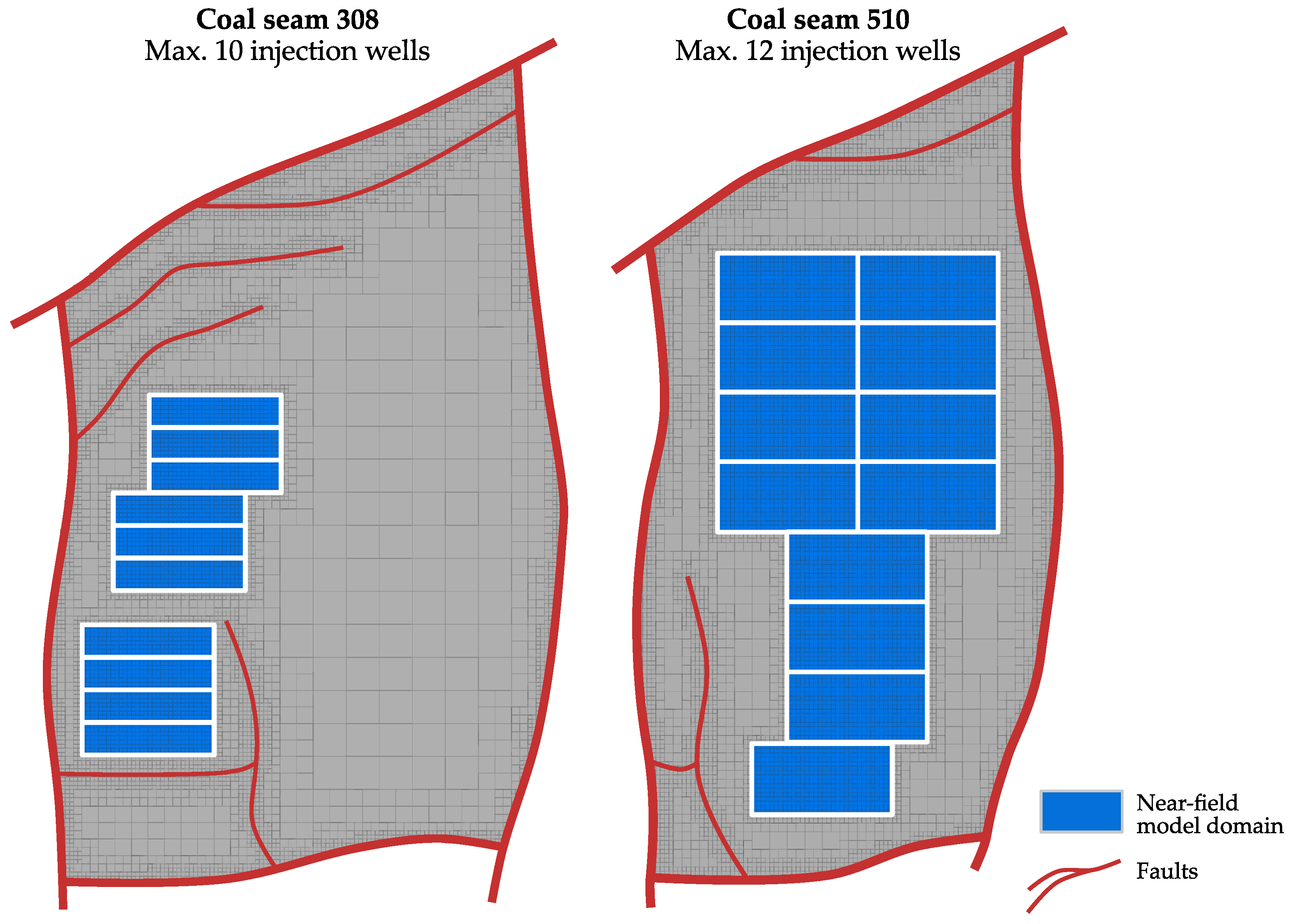
2.5. Injection Well Arrangement

In order to store a preferably high amount of CO2, as many horizontal wells as possible are placed within target coal seams, whereby the total number of panels is an important factor regarding previous economic considerations. An essential criterion to minimise the risk of fault reactivation is the safety distance to the known geological fault zones. It must be chosen carefully in order to not negatively affect the operation and become a concern for health, saftey and the environment. Based on the calculated migration distance of the CO2 from the near-field simulations, a minimum distance of at least 200 m between the horizontal injection blocks (marked in blue in Figure 5) and all nine faults is considered.
Thus, regarding the predefined well length of 500 m, 10 and 12 horizontal wells can be placed within the upper and lower seams, respectively. For coal seam 308, an additional limiting factor exists, since most of the Eastern parts of the coal seam are already mined. Thus, only the Western part of coal seam 308 is taken into consideration for CO2 storage by the present study. Figure 5 shows the resulting injection well arrangement investigated in the numerical simulations: 10 panels can be applied, considering a near-field model domain of 200 m × 800 m. The horizontal extent of coal seam 510 within the tectonic block is smaller and comprises an area of about 2400 m × 4000 m. Due to the respective dip direction, only three of the five minor faults cut the coal seam and must be considered in the well design. Thus, 12 panels can be realised for the investigated near-field domain of 400 m × 800 m lateral size.

3. Results

3.1. Effective Stress Changes in Near-Field Simulations

Two representative simulations were selected from the near-field simulations to assess the hydromechanical impact of CO2 injection for certain stress states: (i) an operational state (1 year), which corresponds to the time of the injection stop, and thus the maximum pressure increase, and (ii) a post-operational state (15 years). Especially changes in effective stress are evaluated, since it has been defined as coupling parameter between the near- and far-field simulations. The changes in effective stress partly result from pore pressure changes due to the injection, and partly from adsorption-induced coal swelling.
For the upper coal seam 308, the highest effective stress change of up to 15.5 MPa occurs for the scenario simulating a constant injection pressure of 1.5 MPa at a simulation time of 1 year. After 15 years of simulation, stresses are relieved and distributed in the near surroundings of the coal seam, since CO2 further migrates after the injection stop. The maximum effective stress increase within the near-field model is still about 7.3 MPa (Figure 6). In this scenario, 2018 t of CO2 are injected per panel (Table 2).
Coal seam 510 is located at a considerably greater depth, resulting in significantly higher injection pressures. The highest effective stress increase amounts to 20.9 MPa for the scenario with a constant injection pressure of 4.5 MPa. After 15 years, the observed maximum effective stress increase within the near-field model is still about 9.4 MPa (Figure 6). The amount of injected CO2 is with 22,139 t per panel, more than ten times higher than that for coal seam 308. This is related to the higher density of CO2 at the given depths, as well as the higher thickness (factor of 4.5) of coal seam 510. The maximum effective stress and the spatial expansion of the pressure increase is considerably lower for scenarios assuming lower injection pressures, as shown in Figure 6.

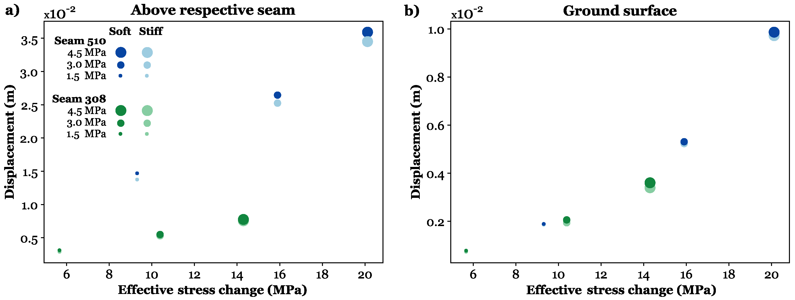
3.2. Vertical Displacements in the Far-Field Simulations

An extensive scenario analysis, consisting of 52 simulations, is conducted to obtain a quantitative understanding of the mechanical processes taking place during the operational and post-operational states. Moreover, the impact of different geological uncertainties, such as the regional stress regime and rock parameter uncertainties are assessed. The elaborated injection well arrangement enables to assess the maximum effect of a CO2 storage operation at the potential commercial-scale site for the 10 and 12 injection panels in coal seam 308 and 510, respectively. A direct hydromechanical effect of CO2 storage is the occurrence of vertical displacements in the rock mass due to considerable changes in the stress field. The results discussed in the following refer to the scenarios considering soft rock properties to present the maximum hydromechanical effects, whereby the impact of rock properties is separately analysed in Section 3.3.

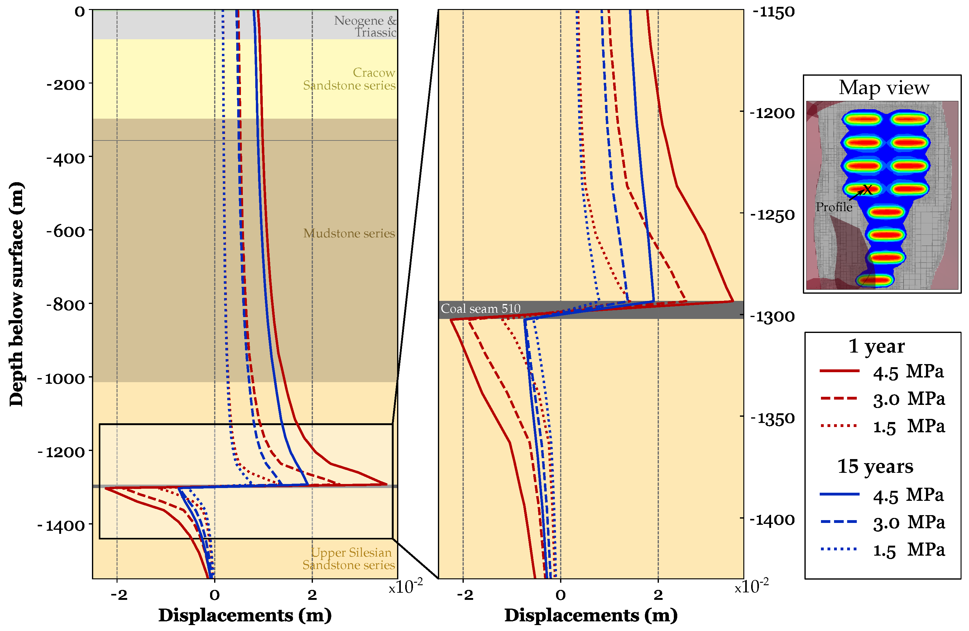
3.2.1. CO2 Injection into Seam 510

Maximum effective pressure changes, and thus vertical displacements occur for a constant injection pressure of 4.5 MPa at a simulation time of 1 year. At this time, the effective pressure change amounts to 20.9 MPa, leading to a maximal vertical displacement of 3.59 cm directly above the coal seam. Due to effective stress changes and the swelling of the coal seam, the rock mass is displaced both, above and below the coal seam, whereby the displacements below the seam are lower due to the higher overburden stresses, and limited ability to displace rock mass into that direction (Figure 7). The dip of the coal seam of 3.1° towards the South is visible within the lateral distribution of vertical displacements, whereby the displacements are slightly higher for the shallower panels. The high displacements directly above the injection well strongly decrease in vertical direction due to the distribution of the stresses, so that the displacements are less localised and occur over a broader area. As Figure 8b,c illustrate, high displacements are also laterally limited to the close vicinity of the injection wells, and strongly decrease within a distance of decametre. Within the Mudstone series, the vertical displacement amounts to circa 1 cm in maximum (Figure 7), and the effect of each single well is not any more recognisable. At the ground surface, the simulated maximum displacement amounts to 0.99 cm. It occurs in the central part of the investigated fault block and slightly decreases towards its boundaries, whereby an area within a distance of 3500 m × 2400 m exhibits a ground surface uplift of more than 0.5 cm. The symmetric structure of the surface displacement is related to the relatively even distribution of horizontal injection wells within coal seam 510.
At the simulation time of 15 years, the maximal vertical displacements directly above the seam are considerably lower, since the CO2 is migrated away from the wells and effective stress distribution in the near-field model domain is less localised (Figure 8). The maximum displacements amount to 1.97 cm and 0.89 cm above coal seam 510 and at the ground surface, respectively. In this scenario, 265,674 t of CO2 are stored within the 12 panels in coal seam 510.
Lower injection pressures of 3.0 MPa and 1.5 MPa result in lower vertical displacements of in maximum 2.64 cm and 1.47 cm above the coal seam, respectively. Moreover, the lower the injection pressure, the lower the difference in vertical displacements between the investigated operational (1 year) and post-operational states (15 years) at the ground surface (Figure 7). The maximum displacements as well as the amounts of injected CO2, depending on the injection pressure for all scenarios, can be found in the Appendix A (Table A1).

3.2.2. CO2 Injection into Seam 308

For all scenarios considering an injection into coal seam 308, the vertical displacements are relatively low compared to those dedicated to seam 510. Maximum effective stress changes occur for the operational state simulating 1.5 MPa constant injection pressure in each of the 10 horizontal wells. Hence, the resulting maximum effective pressure change of 15.5 MPa leads to a vertical displacement of 0.77 cm, which occurs in the centre of each near-field injection panel (Figure 8). At the model top, the ground surface uplift is in maximum 0.34 cm.
At the post-operational state (15 years), the maximal vertical displacements are considerably lower, since the CO2 is migrated away from the wells and the effective stress distribution in the near-field model domain is less localised. In this phase, the maximum displacements are 0.42 cm and 0.25 cm above the coal seam and at the ground surface, respectively. In this scenario, 20,185 t CO2 are stored within the 10 panels in coal seam 308.

3.2.3. CO2 Injection into Both Seams Simultaneously

In order to evaluate the maximum hydromechanical effects of the CO2 storage operation at the selected site, four scenarios are simulated, considering CO2 injection into both coal seams simultaneously. Therefore, the maximum elaborated injection pressures of 1.5 MPa and 4.5 MPa for coal seam 308 and 510 are applied, respectively. Figure 8 illustrates that a CO2 injection into both seams leads to the highest vertical displacements of up to 1.55 cm compared to 0.77 cm and 1.08 cm for the injection operation solely targeting seams 308 and 510, respectively. The maximum ground surface uplift for an injection operation using both seams is 8% higher, with 1.07 cm, compared to the scenario simulating an injection into coal seam 510, only. Moreover, the area exhibiting vertical displacements of more than 0.5 cm is slightly larger with 2500 m × 3000 m, especially in the Western part of the model, where CO2 is injected into seam 308 (Figure 9).
Regarding the changes in rock mass uplift between the operational and post-operational scenario, a clear tendency can be observed: the lower the injection pressure, the lower the difference in ground surface uplift between the operational (1 year) and post-operational states (15 years). For a simultaneous injection into both coal seams, the difference between the operational and post-operational scenarios reduces from 45% above the deeper seam 510 to 23.9% at the shallower seam 308, and 12.1% at the model top. Thus, the hydromechanical impact of CO2 injection is the highest within the immediate surrounding of the injection well, where large and localised effective stress changes occur.
For the simulated storage operation in both coal seams, the injected amount of CO2 is the highest with 285,858 t, whereas the major part of 93% or 265,673 t is injected into coal seam 510, while only 7% or 20,185 t can be stored in coal seam 308. This is related to the higher seam thickness and depth below ground surface, and consequently the higher volume of coal seam 510 and higher density of CO2.

3.3. Effects of Rock Parameter Uncertainties

Elastic rock properties of the main lithological units are varied to assess the effects of parameter uncertainties based on the data available for the study area [43,44]. In the soft rock scenario, the elastic moduli are about half as high as the moduli of the stiff rock scenario (Table 3). Only the properties of the two coal seams are maintained constant, consistent with the near-field simulations.
The vertical displacements are slightly lower in all scenarios, where stiff rock properties are applied (Figure 10). Nevertheless, the differences in vertical displacements amount to 6.4% and 7.3% in maximum above the coal seams 510 and 308, respectively, and are thus relatively small. At the ground surface, the differences are even lower and range between 1.5% and 6.3% for coal seams 510 and 308, respectively. The difference in percentage terms for the vertical displacement above the respective seam decrease with increasing injection pressures and simulation times (Table 4).
Since the integrated effective stress changes lead to coal swelling in the respective target seam, the properties of the surrounding rock mass affect the vertical displacements marginally, only. Nevertheless, elastic properties of the coal seam itself can considerably influence the coal swelling behaviour, and thus the vertical displacements. Due to the previously undertaken extensive field and laboratory investigations, mechanical properties of the coals in the target area are well known, and thus not constitute a systemic uncertainty.

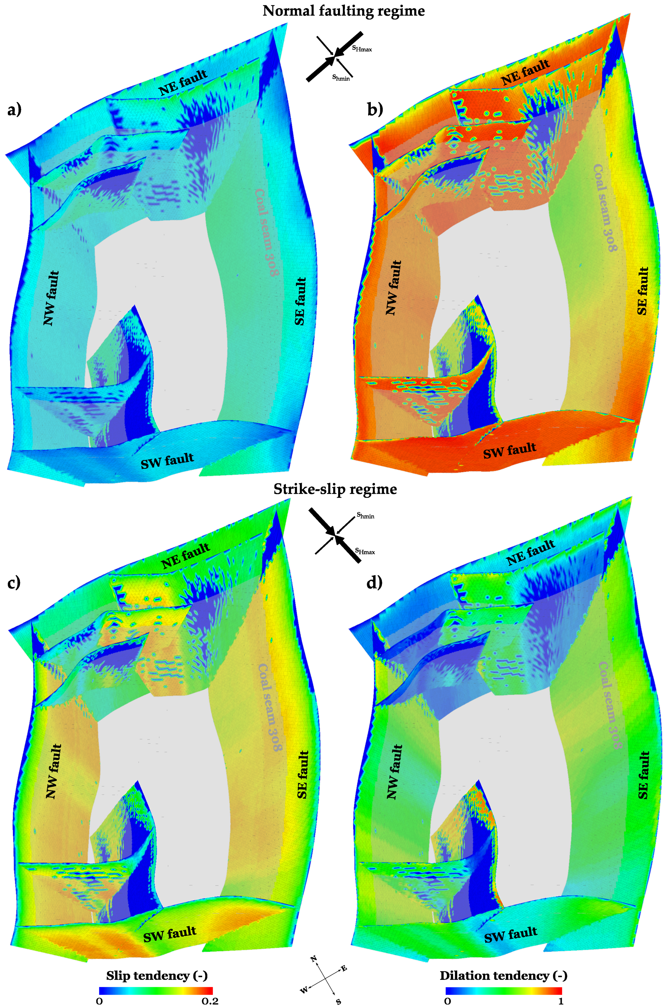
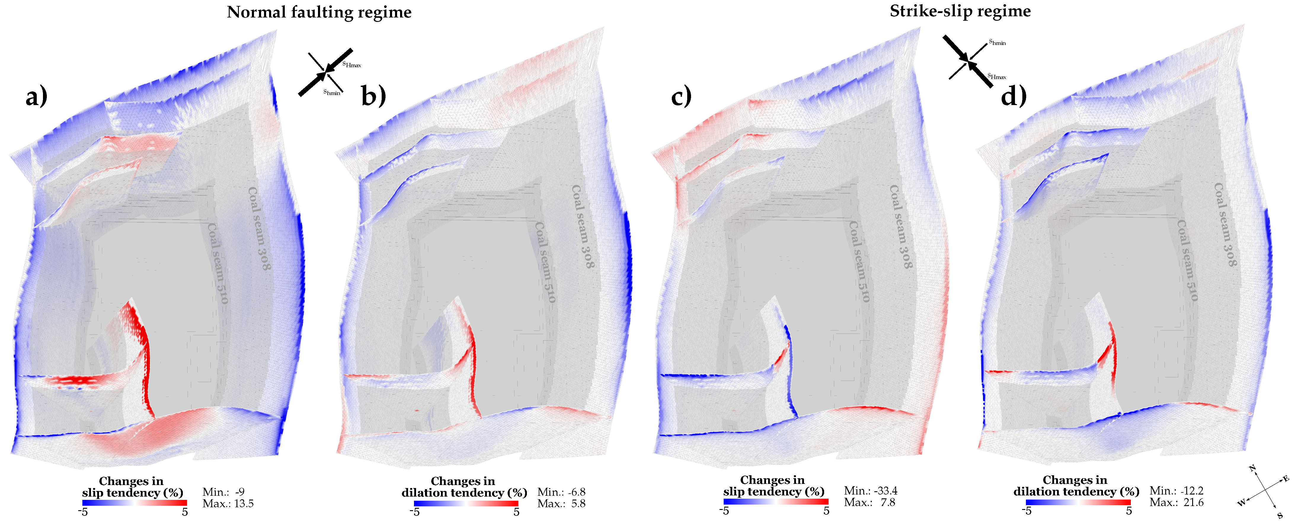
3.4. Stress Field and Fault Reactivation Potential

Besides ground surface uplift, a potential risk of CO2 injection includes the potential reactivation of pre-existing geologic faults due to spatial and temporal changes in the recent stress field. Reactivated faults may then act as preferential leakage pathways for a buoyancy-driven upward migration of CO2. If a pore pressure increase accompanying fluid injection reactivates faults or fault segments, essentially depends on the initial stress state. Therefore, two different stress regimes are assessed as geological uncertainty for the storage site: (i) a normal faulting regime, which has been reported for the local coal deposit, and (ii) a strike-slip regime, which is characteristic for the Upper Silesian Coal Basin. The nine implemented faults present in the study area are examined in the scope of a comprehensive fault slip and dilation tendency analysis. Fault slip tendency is the ratio of resolved shear stress to resolved normal stress at a surface [46], whereby fault dilation tendency is defined by the stress acting normal to a given surface [47]. They describe the likelihood of a plane to slip and to dilate at a certain applied stress state [48]. Both parameters range between 0 and 1, whereby higher values indicate a higher tendency for mechanical failure.
Initial slip and dilation tendencies of the fault system considering a normal faulting regime (SV > SHmax > Shmin) are shown in Figure 11a,b. In this scenario, slip tendencies are generally very low and do not exceed 0.05 in most parts of the fault system. Only the deeper parts of the W-E trending minor faults, as well as the SE fault exhibit slightly higher slip tendencies of up to 0.08. Regarding the dilation tendency, several faults of the system are initially nearly-critically or critically stressed for dilation. Especially the NE and SW faults, and parts of the NW fault exhibit high values of more than 0.85 (Figure 11b). The high dilation tendencies for the assessed normal faulting regime are an indicator for the presence of a conduit behaviour at the respective faults, potentially enabling fluid flow along the fault planes.
Initial slip and dilation tendencies of the fault system considerably vary for a strike-slip regime (SHmax > SV > Shmin) and are displayed in Figure 11c,d. In this scenario, slip tendencies are more than twice the slip tendencies of those of a normal faulting regime, but still relatively low with maximum values of 0.18. There are local variations due to the undulating nature of the faults and the orientation of their fault surfaces, with higher slip tendencies in the deeper parts of the SE and NW faults as well as fault segments striking NW-SE. The dilation tendencies in the strike-slip regime are considerably lower than those in the normal faulting regime. The maximum dilation tendency of 0.92 is only archived in some parts of the NE-SW-trending minor fault in the Southern part of the tectonic block. The SE and NW faults as well as fault segments trending NW-SE show medium dilation tendencies of around 0.5, whereas the NE fault and the W-E-trending minor faults show low dilation tendencies, indicating the presence of a sealing behaviour which prevents fluid migration along the respective fault planes.
Mechanical failure of the ubiquitous joint elements occurs in none of the 52 assessed scenarios. Thus, only the scenarios exhibiting the highest effective stress changes (simultaneous injection into coal seams 308 and 510) are discussed in the following. For the considered normal faulting regime, slip tendency is changing slightly for the operational state. Most of the faults exhibit a minor decrease in slip tendency, especially in the shallower parts, with up to 9% in maximum (Figure 12a). Only along the NW-SE trending parts of the minor faults as well as along the SW fault, a slight increase in slip tendency by 13.5% in maximum is observed. Changes in fault dilation tendencies are even lower, whereby the highest deviations occur in the shallower parts of the faults (Figure 12b). In most parts of the faults, the dilation tendency is slightly reduced by 6.8% in maximum. Only in the NE-SE trending parts of the minor faults, dilation tendency increases by 5.8% in maximum.
For the considered strike-slip regime, slip and dilation tendencies mainly change in the shallower parts of the faults, which located above the coal seam 308 (Figure 12c). The impact of the simulated CO2 injection on the stress regime is still relatively low, with slight changes in slip and dilation tendencies, only. The values for slip tendency in the fault segments in the NE and SW parts of the fault block are reduced by up to 33.4%, whereas values for the fault segments in the SE and NW parts increase by 7.8% in maximum. Nevertheless, even if the initial slip tendencies are higher for the considered strike-slip regime, absolute values are still relatively low. Fault dilation tendencies decrease mostly in the shallower parts of the faults, with 12.2% in maximum (Figure 12d). Some segments of the minor faults in the Southern part of the fault block show an increase in dilation tendency by up to 21.5%. However, the initial values in these areas are relatively low.
Neither fault slip nor dilation, as a potential consequence of slip, arise in the extensive scenario analysis. Consequently, fault reactivation is not expected at any time of CO2 injection in the study area considering the applied injection well arrangement, injection pressures and the given model parametrisation.

4. Discussion

In this study, hydromechanical impacts of a potential CO2 storage in coal beds have been assessed for a commercial-scale operation in the Upper Silesian Coal Basin. Specifically, bandwidths of vertical displacements and fault reactivation depending on the local stress field were investigated as part of a sensitivity analysis, consisting of 52 scenarios. The undertaken analysis allows for obtaining a quantitative understanding of the mechanical processes taking place during the operational and post-operational states. Thereby, these predictive numerical models can increase the safety and sustainability of CO2 storage in coal seams.
The near-field model was employed to simulate CO2 flow within coal seams and coal-CO2 interactions, along with the corresponding changes in permeability and stress. Therefore, a dual porosity modelling approach was applied to represent fluid flow and coal-CO2 interactions within the characteristic microstructure of coal. Although this approach is in general able to express different characteristics of fractures and the rock matrix, conventional dual porosity models are particularly appropriate for reservoirs with highly connected small-scale fractures. For large-scale fractures, hydraulic fractures and highly-localised anisotropy, the dual porosity modelling approach may lead to inaccuracies [23,49]. More attempts are required for an accurate representation of multiscale fractures in fluid flow. In this study, the coal deformation was assumed to be linearly elastic, however, recent work by Chen et al. [50] indicates that nonlinear deformation of fractured coal can also affect the stress field of coal seams. Thus, the nonlinearity of coal deformation should be taken into account in future studies.
The injected amount of CO2 per single panel of 22,139 t in maximum for one year of operation is low compared to the annual emissions of power plants, which are in the range of several Millions of tons CO2. Nevertheless, an injection of CO2 in deep unmineable coal seams can be used to increase the efficiency of coal bed methane recovery [51,52], due to the higher adsorption affinity of CO2 compared to methane [53]. Chećko et al. [51] simulated a CO2 injection into a coal seam of the Upper Silesian Coal Basin combined with enhanced coal bed methane (ECBM) recovery at a depth comparable to that in this study. During a time period of one year, 1,954,213 sm3 (equivalent to 3547 t) of CO2 have been injected via one single horizontal well. When additionally shrinking and swelling of the coal matrix was considered within their model, the aggregate amount of injected CO2 decreased to 625,000 sm3 (equivalent to 1134 t). Taking into account that respective coal seam 405 has a significantly lower thickness of 3 m compared to 9 m for seam 510, the injected amount for one year is in a comparable range to the value reported in this paper. Chećko et al. [51] further showed that a simultaneous injection of CO2 can result in a 50% increase in coal bed methane extraction. Nevertheless, due to the observed reduction in coal permeability, they concluded that hydraulic fracturing is required increase the methane recovery efficiency.
Due to the comparable low aggregate amount of 285,858 t CO2 in maximum, which has been injected via the 22 panels, also the geomechanical impact was limited. The maximum vertical displacements amounted to 3.59 cm and 1.07 cm at the coal seam top and the ground surface, respectively, and no reactivation of the faults zones was to be expected under the given conditions. Nevertheless, the main system-controlling parameters were identified. As expected, the strain increment was proportional to the pressure increase, and thus the injection rate. Magnitude and spatial distribution of displacements further depended on site-specific characteristics, such as seam geometry (e.g., thickness and dip). The simulation results further demonstrated that even considerably lower mechanical properties of the surrounding rock mass exhibited a marginal effect on ground surface uplift, only. Nevertheless, elastic properties of the coal seam itself could considerably influence the coal swelling behaviour, and thus the vertical displacements. Due to the previously undertaken extensive field and laboratory investigations, mechanical properties of the respective coals itself are well known, and thus do not constitute a systemic uncertainty.
The extensive slip and dilation tendency analysis of the fault system in the study area exhibited a fluid conduit behaviour in case of a normal faulting regime for two major faults. Nevertheless, this tendency could not be observed for a strike-slip regime (Section 3.4). Hence, a major uncertainty at potential storage sites is the local stress field, since even if fault integrity is not compromised, faults might be initially hydraulically conductive and could represent local pathways for upward fluid migration. This illustrates the importance in determining the local stress regime as accurately as possible, e.g., via in-situ stress measurements, such as borehole logging, leak-off tests and the recognition of high energy tremors via local focal mechanisms. The results of such analyses can be used to identify the areas and individually known faults of highest reactivation potentials, and thereby guide the operational monitoring at field scale.
Moreover, site-specific modelling assessments of prospective storage sites need to include the entire fault system, whereby especially detailed fault geometries should be integrated. Nevertheless, especially larger faults generally represent highly complex zones, as demonstrated by tectonic field-work studies, e.g., [54,55,56]. Thus, faults zones are composed of various fault segments, Riedel shears, multiple fault strands, dilatational jogs or relay ramps [57]. Parts of these particular fault elements can be sub-seismic, and thus not considered in initial modelling studies. However, they can become extremely relevant within the context of subsurface utilisation, since they represent potential fluid migration pathways in case of reactivation. In this context, also fault properties and their spatial and temporal variability are one of the major unknowns in field-scale hydromechanical simulations. Therefore, the complexity of the fault system and fault parametrisation need to be assessed as part of the extensive risk assessment.

5. Summary and Conclusions

The presented work evaluated the potential hydromechanical effects of CO2 storage in coal seams at a prospective storage site in the Upper Silesian Coal Basin in Poland. In order to examine the complex interacting processes of mechanics, adsorption and multiphase flow with the required accuracy, numerical simulations were performed at near-field and far-field scale. While near-field models of the well bore vicinity have been applied to simulate CO2 injection, adsorption and resulting permeability and stress evolution, the far-field model assessed commercial-scale hydromechanical impacts. Especially, ground surface uplift and the potential reactivation of fault zones were investigated, since faults could act as preferential leakage pathways for the buoyancy-driven upward migration of CO2. In order to flexibly integrate near-field simulation results as internal boundary conditions within the far-field model, a workflow was developed using the effective stress changes as coupling parameter.
The numerical model of the study site, with a spatial extent of 4000 m × 6000 m, comprises five main lithostratigraphic units, two target coal seams as well as the exact geometries of the four major and five minor faults. Two coal seams have been selected as potential storage formations, due to their lateral abundance and sufficient thickness: (i) coal seam 308 has a average thickness of 2 m and is located at an average depth of 405 m, (ii) coal seam 510 is situated at an average depth of 1250 m below the ground surface and has an average thickness of 9 m. A horizontal well configuration, considering a well length of 500 m was examined for injection aiming to enlarged coal-CO2 contact area.
In order to assess the impacts of the injection pressures, well arrangement as well as the effect of different geological uncertainties (regional stress regime and rock properties) for the operational and post-operational states, a comprehensive scenario analysis was conducted, consisting of 52 hydromechanically coupled simulation runs. The highest impact was observed for a simultaneous CO2 injection in both coal seams at constant injection pressures of 1.5 MPa and 4.5 MPa for coal seams 308 and 510, respectively. The resulting maximum vertical displacements amounted to 3.59 cm, 1.27 cm and 1.07 cm directly above the coal seams 510, 308 and at the ground surface, respectively, whereby an area of circa 2500 m × 3000 m exhibited surface uplift of more than 0.5 cm. Hydromechanical impacts of CO2 injection in coal were highest in the immediate surrounding of the injection area, where large and localised effective stress changes occured. Moreover, the larger the distance to the injection location, the smaller the differences between the operational and post-operational states, whereby the differences in ground surface uplift amounted to 10.1%. The storage of 285,858 t of CO2 in maximum was simulated at the prospective commercial-scale site, whereby the major part of 93% or 265,673 t was stored into the deeper coal seam 510, and only 7% or 20,185 t into the shallower seam 308. These differences are related to the considerably higher CO2 density at the depth of coal seam 510, as well as the storage formation volume.
Soft and stiff rock property scenarios were examined, whereby elastic moduli in the soft rock scenario are about 50% of those used in the stiff one. Nevertheless, the differences in vertical displacements above the seams were relatively small with 6.4% and 7.3% in maximum for coal seams 510 and 308 in the operational state, respectively. Hence, the properties of the surrounding rock mass marginally affected the vertical displacements resulting from the pore pressure increase experienced due to CO2 injection.
Moreover, the local fault system present in the study area was examined by means of a comprehensive fault slip and dilation tendency analysis, considering two different stress regimes as geological uncertainty: (i) a strike-slip regime, which is characteristic for the Upper Silesian Coal Basin, as well as (ii) a normal faulting regime, which is reported for the local coal deposit. For the investigated normal faulting regime, slip tendencies were generally very low and did not exceed 0.05 and 0.18 for the normal faulting and strike-slip regime, respectively. Nevertheless, the dilation tendency exhibited high values over 0.85 for the normal faulting regime, indicating potential fluid conduit characteristics of the respective faults, likely enabling CO2 leakage. By contrast, the dilation tendencies were considerably lower in case of a strike-slip regime. Failure of the ubiquitous joint elements representing the fault plane did not occur at any time of CO2 injection considering the applied well design, injection pressures and given parametrisation. Hence, neither fault slip nor dilation, as a potential consequence of the pore pressure increase, were to be expected during the operational or post-operational states, and fault integrity was not compromised at any time of the simulated CO2 storage operation.
Even if fault integrity was not affected, faults may be initially hydraulically conductive and could represent local pathways for upward migration of CO2 or displaced brine. Hence, the local stress regime has to be determined as accurately as possible by in-situ stress measurements. Thereby, regions with the highest fault reactivation potentials or conductive fault segments can be identified to guide the geophysical monitoring during the operational and post-operational phases of the project. The conducted sensitivity analysis enabled to obtain a quantitative understanding of the important mechanical processes during the operational and post-operational phases.
In conclusion, application of numerical models led to specific new insights into hydromechanical processes at a potential CO2 storage site. The coupling of CO2 flow near- and geomechanical far-field modeling approach were proven appropriate for determining hydromechanical impacts at commercial-scale operation. Further, elaborated simulation concept is suitable to identify and quantitatively assess and mitigate these impacts to ensure operational safety. Thereby, the predictive numerical models can contribute to increasing the safety and sustainability of CO2 storage in coal seams. Based on the results presented in this study, assuming that a certain injection pressure (below the 1.5-fold of the hydrostatic pressure) is not exceeded during site operation at the investigated area, it can be concluded that:
  • Vertical surface displacements occur at a tolerable extent with no structural damage of surface infrastructure expected.
  • Parameter variations of rock strength have no significant influence on the hydromechanical impacts of the CO2 storage operation, if conservative rock properties are taken into consideration.
  • Fault reactivation is unlikely and can be further reduced by increasing the amount of in-situ stress measurements to identify regions with high fault reactivation potentials and conductive fault segments.
  • Post-operational impact are unlikely due to the degrading pressure in the reservoir formation.
The presented site-specific findings will contribute to the assessment of potential environmental risks at other CO2 storage sites in coal deposits if CO 2 storage in coal seams becomes economically competitive. The proposed methodology for model coupling across different scales and hydromechanical impact assessment is directly applicable to any coal deposit worldwide.

Author Contributions

Conceptualisation, M.W., T.K. and M.C.; methodology, M.W., T.K. and M.C.; formal analysis, M.W., T.K. and M.C.; investigation, M.W. and M.C.; resources, H.T. and T.K.; data curation, T.U. and B.B.; writing—original draft preparation, M.W. and M.C.; writing—review and editing, C.O. and T.K.; visualisation, M.W.; supervision, T.K. and H.T.; project administration, S.M. All authors have read and agreed to the published version of the manuscript.

Funding

The research was conducted as part of the “Establishing a Research Observatory to Unlock European Coal Seams for Carbon Dioxide Storage (ROCCS)” project. The ROCCS project has received funding from the Research Fund for Coal and Steel under Grant Agreement No. 899336. In addition, supported within the funding programme “Open Access Publikationskosten” Deutsche Forschungsgemeinschaft (DFG, German Research Foundation)—Project Number 491075472. The financial support is gratefully acknowledged.

Data Availability Statement

The data and software will be made available on specific user requests.

Conflicts of Interest

The contact author has declared that none of the authors has any competing interests.

Appendix A

Table A1. All scenarios of the investigated sensitivity analysis regarding initial conditions, maximum displacements and the respective maximum amount of stored CO2.
Coal SeamStress RegimeRock PropertiesInjection Pressure (MPa)Time (years)Max. Displacement above Seam (10−2 m)Max. Displacement at Surface (10−2 m)Amount of CO2 (t)
510SSsoft4.513.590.99265,674
510SSsoft4.5151.970.89265,674
510SSsoft312.640.53150,613
510SSsoft3151.430.50150,613
510SSsoft1.511.470.1960,026
510SSsoft1.5150.820.1860,026
510SSstiff4.513.450.97265,674
510SSstiff4.5151.890.88265,674
510SSstiff312.520.52150,613
510SSstiff3151.370.49150,613
510SSstiff1.511.370.1960,026
510SSstiff1.5150.780.1860,026
510NFsoft4.513.590.99265,674
510NFsoft4.5151.970.89265,674
510NFsoft312.640.53150,613
510NFsoft3151.430.50150,613
510NFsoft1.511.470.1960,026
510NFsoft1.5150.820.1860,026
510NFstiff4.513.450.97265,674
510NFstiff4.5151.890.88265,674
510NFstiff312.520.52150,613
510NFstiff3151.370.49150,613
510NFstiff1.511.370.1960,026
510NFstiff1.5150.780.1860,026
308SSsoft1.510.770.3420,185
308SSsoft1.5150.420.2520,185
308SSsoft110.550.1912,392
308SSsoft1150.340.1712,392
308SSsoft0.510.310.075599
308SSsoft0.5150.210.085599
308SSstiff1.510.760.3620,185
308SSstiff1.5150.410.2620,185
308SSstiff110.530.2112,392
308SSstiff1150.330.1812,392
308SSstiff0.510.290.085599
308SSstiff0.5150.200.085599
308NFsoft1.510.770.3420,185
308NFsoft1.5150.420.2520,185
308NFsoft110.550.1912,392
308NFsoft1150.340.1712,392
308NFsoft0.510.310.075599
308NFsoft0.5150.210.085599
308NFstiff1.510.760.3620,185
308NFstiff1.5150.410.2620,185
308NFstiff110.530.2112,392
308NFstiff1150.330.1812,392
308NFstiff0.510.290.085599
308NFstiff0.5150.200.085599
308 and 510SSsoft1.5 and 4.513.591.07285,858
308 and 510SSsoft1.5 and 4.5151.970.94285,858
308 and 510NFsoft1.5 and 4.513.591.07285,858
308 and 510NFsoft1.5 and 4.5151.970.94285,858
SS—Strike-slip regime, NF—Normal faulting regime.

References

  1. IPCC. Special Report: Carbon Dioxide Capture and Storage; Technical Report; Cambridge University Press: Cambridge, UK, 2005. [Google Scholar]
  2. Masoudian, M.S. Multiphysics of carbon dioxide sequestration in coalbeds: A review with a focus on geomechanical characteristics of coal. J. Rock Mech. Geotech. Eng. 2016, 8, 93–112. [Google Scholar] [CrossRef] [Green Version]
  3. White, C.M.; Smith, D.H.; Jones, K.L.; Goodman, A.L.; Jikich, S.A.; LaCount, R.B.; DuBose, S.B.; Ozdemir, E.; Morsi, B.I.; Schroeder, K.T. Sequestration of carbon dioxide in coal with enhanced coalbed methane recovery—A review. Energy Fuels 2005, 19, 659–724. [Google Scholar] [CrossRef]
  4. Sun, L.; Dou, H.; Li, Z.; Hu, Y.; Hao, X. Assessment of CO2 storage potential and carbon capture, utilization and storage prospect in China. J. Energy Inst. 2018, 91, 970–977. [Google Scholar] [CrossRef]
  5. Vangkilde-Pedersen, T.; Anthonsen, K.L.; Smith, N.; Kirk, K.; Neele, F.; van der Meer, B.; Le Gallo, Y.; Bossie-Codreanu, D.; Wojcicki, A.; Le Nindre, Y.M.; et al. Assessing European capacity for geological storage of carbon dioxide—The EU GeoCapacity project. Energy Procedia 2009, 1, 2663–2670. [Google Scholar] [CrossRef] [Green Version]
  6. Hong, W.Y. A techno-economic review on carbon capture, utilisation and storage systems for achieving a net-zero CO2 emissions future. Carbon Capture Sci. Technol. 2022, 3, 100044. [Google Scholar] [CrossRef]
  7. Dutta, P.; Zoback, M.D. CO2 sequestration into the Wyodak coal seam of Powder River Basin—Preliminary reservoir characterization and simulation. Int. J. Greenh. Gas Control 2012, 9, 103–116. [Google Scholar] [CrossRef]
  8. Van Bergen, F.; Pagnier, H.; Krzystolik, P. Field experiment of enhanced coalbed methane-CO2 in the upper Silesian basin in Poland. Environ. Geosci. 2006, 13, 201–224. [Google Scholar] [CrossRef]
  9. Steadman, E.N.; Anagnost, K.K.; Botnen, B.W.; Botnen, L.A.; Daly, D.J.; Gorecki, C.D.; Harju, J.A.; Jensen, M.D.; Peck, W.D.; Romuld, L.; et al. The Plains CO2 Reduction (PCOR) partnership: Developing Carbon management options for the central interior of North America. Energy Procedia 2011, 4, 6061–6068. [Google Scholar] [CrossRef] [Green Version]
  10. Sheng, Y.; Benderev, A.; Bukolska, D.; Eshiet, K.I.I.; da Gama, C.D.; Gorka, T.; Green, M.; Hristov, N.; Katsimpardi, I.; Kempka, T.; et al. Interdisciplinary studies on the technical and economic feasibility of deep underground coal gasification with CO2 storage in bulgaria. Mitig. Adapt. Strateg. Glob. Chang. 2016, 21, 595–627. [Google Scholar] [CrossRef] [Green Version]
  11. Fujioka, M.; Yamaguchi, S.; Nako, M. CO2-ECBM field tests in the Ishikari Coal Basin of Japan. Int. J. Coal Geol. 2010, 82, 287–298. [Google Scholar] [CrossRef]
  12. Van Bergen, F.; Krzystolik, P.; van Wageningen, N.; Pagnier, H.; Jura, B.; Skiba, J.; Winthaegen, P.; Kobiela, Z. Production of gas from coal seams in the Upper Silesian Coal Basin in Poland in the post-injection period of an ECBM pilot site. Int. J. Coal Geol. 2009, 77, 175–187. [Google Scholar] [CrossRef]
  13. Van Bergen, F.; Winthaegen, P.; Pagnier, H.; Krzystolik, P.; Jura, B.; Skiba, J.; van Wageningen, N. Assessment of CO2 storage performance of the Enhanced Coalbed Methane pilot site in Kaniow. Energy Procedia 2009, 1, 3407–3414. [Google Scholar] [CrossRef] [Green Version]
  14. Fang, H.; Sang, S.; Liu, S. Establishment of dynamic permeability model of coal reservoir and its numerical simulation during the CO2-ECBM process. J. Pet. Sci. Eng. 2019, 179, 885–898. [Google Scholar] [CrossRef]
  15. Busch, A.; Gensterblum, Y. CBM and CO2-ECBM related sorption processes in coal: A review. Int. J. Coal Geol. 2011, 87, 49–71. [Google Scholar] [CrossRef]
  16. Cai, Y.; Pan, Z.; Liu, D.; Zheng, G.; Tang, S.; Connell, L.; Yao, Y.; Zhou, Y. Effects of pressure and temperature on gas diffusion and flow for primary and enhanced coalbed methane recovery. Energy Explor. Exploit. 2014, 32, 601–619. [Google Scholar] [CrossRef] [Green Version]
  17. Pone, J.D.; Halleck, P.M.; Mathews, J.P. Sorption capacity and sorption kinetic measurements of CO2 and CH4 in confined and unconfined bituminous coal. Energy Fuels 2009, 23, 4688–4695. [Google Scholar] [CrossRef]
  18. Masum, S.A.; Chen, M.; Hosking, L.J.; Stańczyk, K.; Kapusta, K.; Thomas, H.R. A numerical modelling study to support design of an in-situ CO2 injection test facility using horizontal injection well in a shallow-depth coal seam. Int. J. Greenh. Gas Control 2022, 119, 103725. [Google Scholar] [CrossRef]
  19. Ridha, S.; Pratama, E.; Ismail, S. Performance assessment of CO2 sequestration in a horizontal well for enhanced coalbed methane recovery in deep unmineable coal seams. Chem. Eng. Trans. 2017, 56, 589–594. [Google Scholar]
  20. Ren, J.; Zhang, L.; Ren, S.; Lin, J.; Meng, S.; Ren, G.; Gentzis, T. Multi-branched horizontal wells for coalbed methane production: Field performance and well structure analysis. Int. J. Coal Geol. 2014, 131, 52–64. [Google Scholar] [CrossRef]
  21. Connell, L.D.; Pan, Z.; Camilleri, M.; Meng, S.; Down, D.; Carras, J.; Zhang, W.; Fu, X.; Guo, B.; Briggs, C.; et al. Description of a CO2 enhanced coal bed methane field trial using a multi-lateral horizontal well. Int. J. Greenh. Gas Control 2014, 26, 204–219. [Google Scholar] [CrossRef]
  22. Gentzis, T.; Bolen, D. The use of numerical simulation in predicting coalbed methane producibility from the Gates coals, Alberta Inner Foothills, Canada: Comparison with Mannville coal CBM production in the Alberta Syncline. Int. J. Coal Geol. 2008, 74, 215–236. [Google Scholar] [CrossRef]
  23. Sams, W.; Bromhal, G.; Jikich, S.; Odusote, O.; Ertekin, T.; Smith, D. Simulating Carbon Dioxide Sequestration/ECBM Production in Coal Seams: Effects of Permeability Anisotropies and Other Coal Properties; SPE 84423; Society of Petroleum Engineers: Richardson, TX, USA, 2003. [Google Scholar]
  24. Zhang, J.; Feng, Q.; Zhang, X.; Hu, Q.; Wen, S.; Chen, D.; Zhai, Y.; Yan, X. Multi-fractured horizontal well for improved coalbed methane production in eastern Ordos basin, China: Field observations and numerical simulations. J. Pet. Sci. Eng. 2020, 194, 107488. [Google Scholar] [CrossRef]
  25. Liu, G.; Smirnov, A.V. Carbon sequestration in coal-beds with structural deformation effects. Energy Convers. Manag. 2009, 50, 1586–1594. [Google Scholar] [CrossRef]
  26. Connell, L.D.; Detournay, C. Coupled flow and geomechanical processes during enhanced coal seam methane recovery through CO2 sequestration. Int. J. Coal Geol. 2009, 77, 222–233. [Google Scholar] [CrossRef]
  27. Chen, Z.; Liu, J.; Elsworth, D.; Connell, L.D.; Pan, Z. Impact of CO2 injection and differential deformation on CO2 injectivity under in-situ stress conditions. Int. J. Coal Geol. 2010, 81, 97–108. [Google Scholar] [CrossRef]
  28. Kedzior, S. Accumulation of coal-bed methane in the south-west part of the Upper Silesian Coal Basin (southern Poland). Int. J. Coal Geol. 2009, 80, 20–34. [Google Scholar] [CrossRef]
  29. Smoliński, A.; Rompalski, P.; Cybulski, K.; Chećko, J.; Howaniec, N. Chemometric study of trace elements in hard coals of the upper Silesian Coal Basin, Poland. Sci. World J. 2014, 2014, 234204. [Google Scholar] [CrossRef] [Green Version]
  30. Thomas, H.R.; Rees, S.W.; Sloper, N.J. Three-dimensional heat, moisture and air transfer in unsaturated soils. Int. J. Numer. Anal. Methods Geomech. 1998, 22, 75–95. [Google Scholar] [CrossRef]
  31. Chen, M.; Masum, S.A.; Thomas, H.R. 3D hybrid coupled dual continuum and discrete fracture model for simulation of CO2 injection into stimulated coal reservoirs with parallel implementation. Int. J. Coal Geol. 2022, 262, 104103. [Google Scholar] [CrossRef]
  32. Chen, M.; Masum, S.; Sadasivam, S.; Thomas, H. Modelling anisotropic adsorption-induced coal swelling and stress-dependent anisotropic permeability. Int. J. Rock Mech. Min. Sci. 2022, 153, 105107. [Google Scholar] [CrossRef]
  33. Van Wageningen, W.F.; Wentinck, H.M.; Otto, C. Report and modeling of the MOVECBM field tests in Poland and Slovenia. Energy Procedia 2009, 1, 2071–2078. [Google Scholar] [CrossRef] [Green Version]
  34. Konecny, P.; Kozusnikova, A. Influence of stress on the permeability of coal and sedimentary rocks of the Upper Silesian basin. Int. J. Rock Mech. Min. Sci. 2011, 48, 347–352. [Google Scholar] [CrossRef]
  35. Pagnier, H.; van Bergen, F.; Krzystolik, P.; Skiba, J.; Jura, B.; Hadro, J.; Wentink, P.; De-Smedt, G.; Kretzschmar, H.J.; Fröbel, J.; et al. Reduction of CO2 Emission by Means of CO2 Storage in Coal Seams in the Silesian Coal Basin of Poland; RECOPOL (Final Report); 2006. Available online: https://ieaghg.org/docs/General_Docs/Reports/2006-10%20Final%20RECOPOL%20Report.pdf (accessed on 3 April 2023).
  36. Majewska, Z.; Majewski, S.; Zietek, J. Swelling of coal induced by cyclic sorption/desorption of gas: Experimental observations indicating changes in coal structure due to sorption of CO2 and CH4. Int. J. Coal Geol. 2010, 83, 475–483. [Google Scholar] [CrossRef]
  37. Chen, M.; Hosking, L.J.; Sandford, R.J.; Thomas, H.R. Dual porosity modelling of the coupled mechanical response of coal to gas flow and adsorption. Int. J. Coal Geol. 2019, 205, 115–125. [Google Scholar] [CrossRef] [Green Version]
  38. Reeves, S.R.; Taillefert, A. Reservoir Modeling for the Design of the RECOPOL CO2 Sequestration Project, Poland; Topical Report, DOE Contract No. DE-FC26-00NT40924; 2002. Available online: https://www.adv-res.com/Coal-Seq_Consortium/ECBM_Sequestration_Knowledge_Base/Coal-Seq%20Topical%20Reports/Topical%20Report%20-%20RECOPOL%20Design%20Modelling.pdf (accessed on 3 April 2023).
  39. Hol, S.; Spiers, C.J. Competition between adsorption-induced swelling and elastic compression of coal at CO2 pressures up to 100 MPa. J. Mech. Phys. Solids 2012, 60, 1862–1882. [Google Scholar] [CrossRef]
  40. Itasca Consulting Group, Inc. FLAC3D Software Version 5.01. User’s Manual. Advanced Three-Dimensional Continuum Modelling for Geotechnical Analysis of Rock, Soil and Structural Support; Itasca Consulting Group, Inc.: Minneapolis, MN, USA, 2014. [Google Scholar]
  41. Otto, C.; Kempka, T.; Kapusta, K.; Stańczyk, K. Fault reactivation can generate hydraulic short circuits in underground coal gasification—New insights from regional-scale thermo-mechanical 3D modeling. Minerals 2016, 6, 101. [Google Scholar] [CrossRef] [Green Version]
  42. Kempka, T.; Nielsen, C.M.; Frykman, P.; Shi, J.Q.; Bacci, G.; Dalhoff, F. Coupled hydro-mechanical simulations of CO2 storage supported by pressure management demonstrate synergy benefits from simultaneous formation fluid extraction. Oil Gas Sci. Technol. 2015, 70, 599–613. [Google Scholar] [CrossRef] [Green Version]
  43. Chećko, J. Analysis of geological, hydrogeological and mining conditions in the area of the developed georeactor located in KWK Wieczorek mine. Prz. Górn. 2013, 69, 37–45. [Google Scholar]
  44. Dubinski, J.; Stec, K.; Bukowska, M. Geomechanical and tectonophysical conditions of mining-induced seismicity in the Upper Silesian Coal Basin in Poland: A case study. Arch. Min. Sci. 2019, 64, 163–180. [Google Scholar] [CrossRef]
  45. Jarosiński, M. Recent tectonic stress field investigations in Poland: A state of the art. Geol. Q. 2006, 50, 303–321. [Google Scholar]
  46. Morris, A.; Ferrill, D.A.; Henderson, D.B. Slip-tendency analysis and fault reactivation. Geology 1996, 24, 275–278. [Google Scholar] [CrossRef]
  47. Ferrill, D.A. Stressed rock strains groundwater at Yucca Mountain, Nevada. GSA Today 1999, 9, 1–8. [Google Scholar]
  48. Hobbs, B.E.; Means, W.D.; Williams, P.F. An Outline of Structural Geology; Wiley: New York, NY, USA, 1976; Volume 25. [Google Scholar]
  49. Moinfar, A.; Varavei, A.; Sepehrnoori, K.; Johns, R.T. Development of a coupled dual continuum and discrete fracture model for the simulation of unconventional reservoirs. In Proceedings of the SPE Reservoir Simulation Symposium, The Woodlands, TX, USA, 18–20 February 2013; Volume 2, pp. 978–994. [Google Scholar] [CrossRef]
  50. Chen, M.; Masum, S.A.; Thomas, H.R. Three-dimensional cleat scale modelling of gas transport processes in deformable fractured coal reservoirs. Gas Sci. Eng. 2023, 110, 204901. [Google Scholar] [CrossRef]
  51. Chećko, J.; Urych, T.; Magdziarczyk, M.; Smolinski, A. Research on the processes of injecting CO2 into coal seams with CH4 recovery using horizontal wells. Energies 2020, 13, 416. [Google Scholar] [CrossRef] [Green Version]
  52. Wong, S.; Gunter, W.D.; Mavor, M.J. Economics of CO2 sequestration in coalbed methane reservoirs. In Proceedings of the SPE/CERI Gas Technology Symposium 2000, GTS 2000, Calgary, AB, Canada, 3–5 April 2000. [Google Scholar] [CrossRef]
  53. Godec, M.; Koperna, G.; Gale, J. CO2-ECBM: A review of its status and global potential. Energy Procedia 2014, 63, 5858–5869. [Google Scholar] [CrossRef] [Green Version]
  54. Price, N.J.; Cosgrove, J.W. Analysis of Geological Structures; Cambridge University Press: Cambridge, UK, 1990. [Google Scholar]
  55. Van der Zee, W. Dynamics of Fault Gouge Development in Layered Sand-Clay Sequences; Shaker Verlag GmbH: Dueren, Germany, 2002. [Google Scholar]
  56. Koledoye, B.A.; Aydin, A.; May, E. A new process-based methodology for analysis of shale smear along normal faults in the Niger Delta. AAPG Bull. 2003, 87, 445–463. [Google Scholar] [CrossRef]
  57. Ligtenberg, J.H. Detection of fluid migration pathways in seismic data: Implications for fault seal analysis. Basin Res. 2005, 17, 141–153. [Google Scholar] [CrossRef]
Figure 1. (a) Schematic illustration of the characteristic lithological sequence including the two selected target coal seams. (b) Typical coal microstructure consisting of a cleat network and a matrix, whereby both are considered in the near-field model by a dual porosity approach. (c) Dimensions of the near-field model domain simulating CO 2 injection and coal-CO 2 interactions in the borehole vicinity.
Energies 16 03279 g001
Figure 2. CO 2 adsorption isotherm (blue line) and adsorption-induced swelling strain (orange line) used in the simulations [33].
Energies 16 03279 g002
Figure 3. Numerical model of the potential storage site. The entire model domain has the three-fold size of the tectonic block to avoid mechanical impacts on the lateral model boundary conditions. The thickness of all layers, aside from the coal seams, varies within the model as a result of the varying dip directions and angles of the lithostratigraphic top surfaces.
Energies 16 03279 g003
Figure 4. Comparisons of WNW-ESE (above) and NNE-SSW (bottom) cross sections of the numerical model with the respective cross-sections of the structural geologic model (illustrated cut-outs on the right).
Energies 16 03279 g004
Figure 5. Injection well arrangement for coal seams 308 and 510 with 10 and 12 panels, respectively. The near-field model domain (blue) has an extent of 200 m × 800 m and 400 m × 800 m for seams 308 and 510, respectively.
Energies 16 03279 g005
Figure 6. Effective stress changes in coal seams (a) 308 and (b) 510 for the investigated scenarios at simulation times of 1 year (operational state) and 15 years (post-operational state).
Energies 16 03279 g006
Figure 7. Vertical profile from the model top through one of the horizontal injection panels of coal seam 510 exhibiting the simulated vertical displacements for constant injection pressures of 4.5 MPa, 3.0 MPa and 1.5 MPa during the operational (1 year) and post-operational state (15 years).
Energies 16 03279 g007
Figure 8. Vertical displacements (a) at the ground surface, (b) the top of coal seam 308, and (c) seam 510 for a CO 2 injection into seam 308, 510 and both seams simultaneously considering the operational and post-operational scenarios.
Energies 16 03279 g008
Figure 9. Simulated vertical displacements in (a) map view above coal seam 510, (b) at the ground surface and (c) along a NNE-SSW trending cross section as for an injection in both coal seams with the respective maximum injection pressures for the operational state (1 year).
Energies 16 03279 g009
Figure 10. Maximum vertical displacements (a) above the respective coal seams as well as (b) the ground surface compared for the scenarios with soft and stiff rock properties for the operational state (1 year).
Energies 16 03279 g010
Figure 11. (a) Simulated slip and (b) dilation tendencies for the fault system of the study area for a normal faulting regime, as well as (c) slip and (d) dilation tendencies for a predominant strike-slip regime.
Energies 16 03279 g011
Figure 12. Simulated changes in (a) slip and (b) dilation tendencies at the operational state (1 year) for a normal faulting regime and a CO 2 storage within both coal seams. (c) Slip and (d) dilation tendencies for a strike-slip regime.
Energies 16 03279 g012
Table 1. Hydrochemical parameters of the near-field model.
Parameter ValueReference
Intrinsic permeability (mD)Seam 3081.0[34]
Seam 5100.3[35]
Initial fracture porosity (-)Seam 3080.015[34]
Seam 5100.006[35]
Matrix porosity (-) 0.04[36]
Gas viscosity (Pa·s) 1.84 × 10⁻⁵[37]
Unstressed fracture compressibility (MPa−1) 0.029[38]
Matrix elastic modulus (GPa) 11.5[39]
Langmuir pressure constant (MPa) 2.6[33]
Langmuir volume constant (mol/kg) 0.76[33]
Table 2. Injection and effective pressures as well as the amount of injected CO2 per single well for the six near-field scenarios.
Coal SeamConstant Injection Pressure (MPa)Pressure Increase in Relation to Respective Hydrostatic Pressure (-)Amount of Injected CO2 (t)Maximum Effective Pressure Change (MPa)
1 year15 years
3081.51.36201815.57.3
1.01.24123911.86.3
0.51.125607.24.4
5104.51.3722,13920.99.4
3.01.2912,55117.17.6
1.51.12500211.25.2
Table 3. Geomechanical parameters used for the undertaken scenario analysis.
Property QuaternaryNeogene and TriassicCracow Sandstone SeriesMudstone SeriesCoal (308)Upper Silesian SandstoneCoal (510)Stiff Basement
Young’s modulusSoft223.33.61.85.92.280
(GPa)Stiff557.58.11.88.42.280
Poisson’s ratio (-)0.40.250.210.260.30.230.30.27
Tensile strength (MPa)0.01.02.02.60.62.60.63.8
Cohesion (MPa)0.02.014.918.13.814.03.810.9
Friction angle (°)3531313131313131
Density (kg/m3)21002200211524181388237813882465
Table 4. Percentage deviation in maximum displacements between the soft and stiff rock property scenarios.
Constant Injection Pressure (MPa)Max. Displacements for the Stiff Property Scenario (%)
Above Coal SeamAt Ground Surface
1 year15 years1 year15 years
Coal seam 3081.5−2.5−1.7−6.1−5.5
1.0−3.4−2.5−6.2−5.9
0.5−7.3−4.6−6.3−6.3
Coal seam 5104.5−3.9−3.9−1.5−1.4
3.0−4.6−3.7−1.5−1.5
1.5−6.4−4.9−1.5−1.5
Disclaimer/Publisher’s Note: The statements, opinions and data contained in all publications are solely those of the individual author(s) and contributor(s) and not of MDPI and/or the editor(s). MDPI and/or the editor(s) disclaim responsibility for any injury to people or property resulting from any ideas, methods, instructions or products referred to in the content.

