
A Review on Recent Developments of RCCI Engines Operated with Alternative Fuels

 , , ,
, , ,  and
and 
Abstract
:1. Introduction
1.1. Basics of CI Engine Operation
1.2. Fundamentals of RCCI
Heat Release
2. Effect of Operating Parameters on Emissions of RCCI Engine
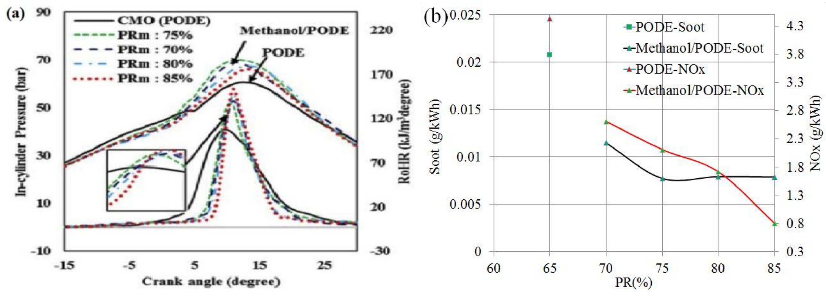
2.1. Low-Reactive Fuels
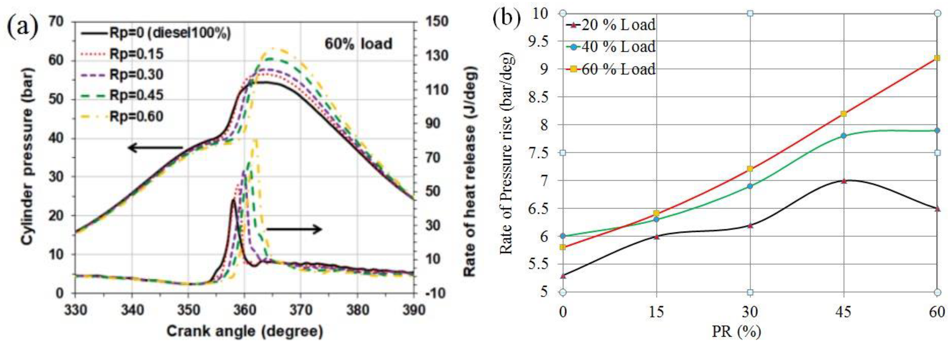
2.2. Premixing Ratio
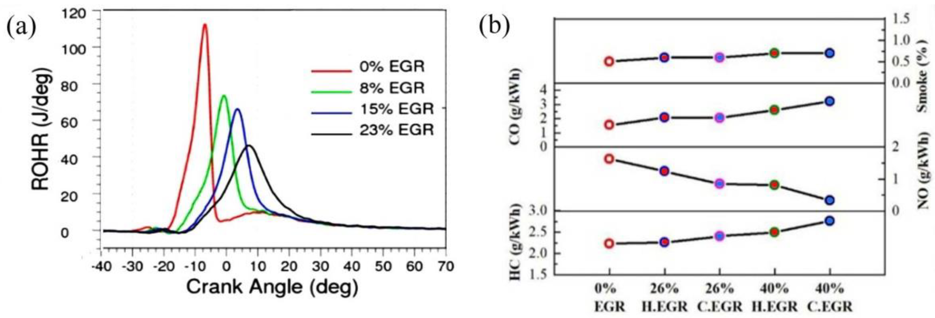
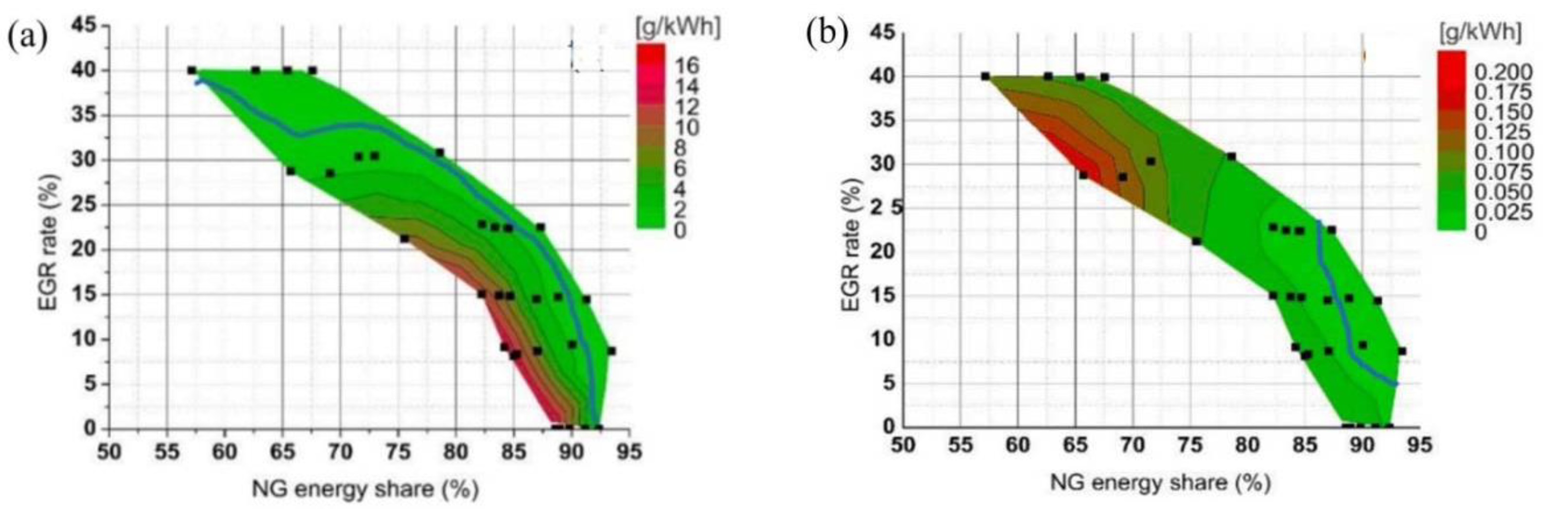
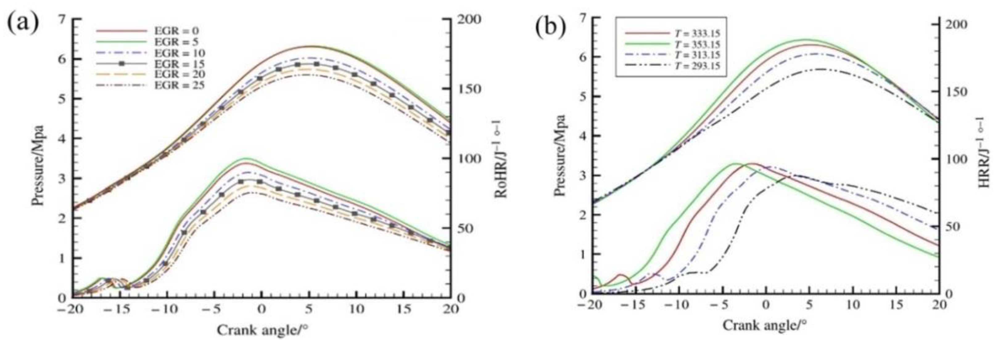
2.3. EGR Rate
2.4. Compression Ratio

| Authors | LRF/HRF | CR | PR%/EGR% | IMEP Bar | NOx % | Soot % | HC/CO % |
|---|---|---|---|---|---|---|---|
| [64] | Biomass/diesel | 12–18 | 34–48/NA | 3.17, 4.23 | NA | NA | +/+ |
| [62] | CNG/diesel | 14 & 17 | 63.4−88.9/42, 51 | 7, 9, 10 | − | − | +/+ |
| [65] | Gasoline/diesel | 14.4 & 11 | 75 & 80–70/NA | 6.9 & 14–23 | − | − | +/+ |
| [66] | CO2/diesel | 20 | 25–45/NA | 6.5 | 44 + | 10 + | 18/6 +/+ |
| [67] | CNG/safflower biodiesel | 13–19 | 5–15/NA | 17.34 | 50 − | 39 − | 1/4 +/+ |

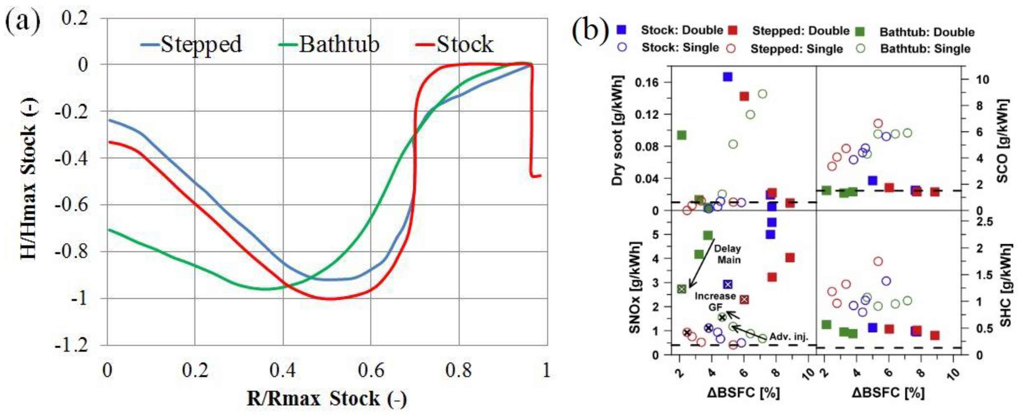
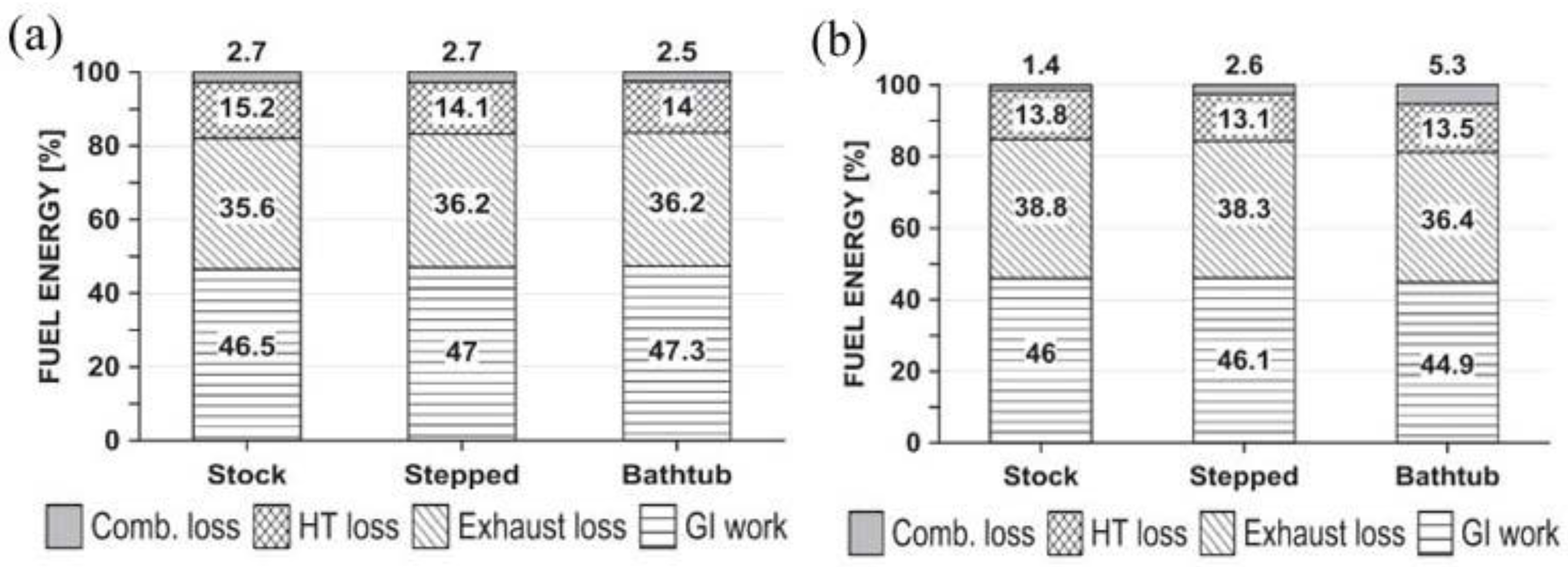
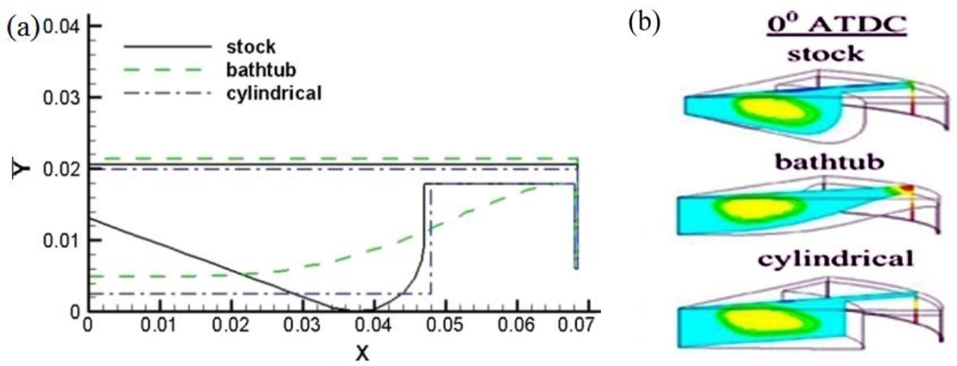
2.5. Bowl Geometry
2.6. High Load Operation of RCCI
3. Discussion and Directions for Future Research
4. Conclusions
Author Contributions
Funding
Data Availability Statement
Conflicts of Interest
Abbreviations
| BMEP | Brake mean effective pressure |
| BSFC | Brake-specific fuel consumption |
| CA | Crank angle |
| CDC | Conventional diesel combustion |
| CH3OH | Methanol |
| CI | Compression ignition |
| CNG | Compressed natural gas |
| CO | Carbon monoxide |
| CO2 | Carbon dioxide |
| CR | Compression ratio |
| DI | Direct injection |
| EGR | Exhaust gas recirculation |
| HC | Hydrocarbon |
| HCCI | Homogeneous charge compression Ignition |
| HRR | Heat release rate |
| HRF | High-reactivity fuel |
| HTHR | High-temperature heat release |
| ID | Ignition delay |
| IVC | Inlet valve closing |
| LRF | Low-reactivity fuel |
| LTC | Low-temperature combustion |
| LTHR | Low-temperature heat release |
| NOx | Nitrogen oxide |
| NTC | Negative-temperature coefficient |
| PCCI | Premixed charge compression ignition |
| PFI | Port fuel injection |
| PODE | Polyoxy methylene dimethyl ethers |
| PR | Premixing ratio |
| RPM | Revolution per minute |
| RCCI | Reactivity-controlled compression ignition |
| SI | Spark ignition |
| SOC | Start of combustion |
| SOI | Start of injection |
| TDC | Top dead center |
References
- Prasad, R.; Bella, V.R. A review on diesel soot emission, its effect and control. Bull. Chem. React. Eng. Catal. 2010, 5, 69. [Google Scholar] [CrossRef]
- Bhandarkar, S. Vehicular pollution, their effect on human health and mitigation measures. Veh. Eng. 2013, 1, 33–40. [Google Scholar]
- Reitz, R.D. Directions in internal combustion engine research. Combust. Flame 2013, 160, 1–8. [Google Scholar] [CrossRef]
- Lindqvist, K. Emission standards for light and heavy road vehicles. AirClim Factsheet 2012, Volume 25. Available online: https://www.airclim.org/sites/default/files/documents/Factsheet-emission-standards.pdf (accessed on 16 January 2023).
- Zimmermann, K.; Haefeli, R.; Ganser, M. Engine performances with advanced common rail injector Design. In Proceedings of the ASME 2017 Internal Combustion Engine Division Fall Technical Conference, Washington, DC, USA, 15–18 October 2017; American Society of Mechanical Engineers: New York, NY, USA, 2017; p. 58318. [Google Scholar] [CrossRef]
- Yu, R.C.; Shahed, S.M. Effects of injection timing and exhaust gas recirculation on emissions from a DI diesel engine. SAE Trans. 1981, 90, 3873–3883. [Google Scholar] [CrossRef]
- Brandi, F.K.; Affenzeller, J.; Thien, G.E. Some strategies to meet future noise regulations for truck engines. SAE Trans. 1987, 96, 1510–1521. [Google Scholar] [CrossRef]
- Reddy, D.S.K.; Ghodke, P.; Velusamy, R. Indigenous Knowledge Generation in the Design of Automotive Engines. In Proceedings of the India International Science Festival, Department of Science and Technology, Government of India, New Delhi, India, 4–8 December 2015. Paper No. 120. [Google Scholar]
- Shaik, R.; Kumar, A.; Padmavathi, R.; Jagan, G.; Anshul, A.; Ganguly, G.; Dwarshala, K.; Ravishankar, S.S. Computational and Experimental Investigations to Improve Performance, Emissions and Fuel Efficiency of a Single Cylinder Diesel Engine; SAE Technical Paper; SAE: Warrendale, PA, USA, 2015; Paper No. 99. [Google Scholar]
- Jackson, M.W. Effect of catalytic emission control on exhaust hydrocarbon composition and reactivity. SAE Trans. 1978, 87, 2304–2327. [Google Scholar]
- Abthoff, J.; Schuster, H.D.; Langer, H.J.; Loose, G. The Regenerable Trap Oxidizer—An Emission Control Technique for Diesel Engines. SAE Trans. 1985, 94, 128–138. [Google Scholar] [CrossRef]
- Kummer, J.T. Catalysts for automobile emission control. Prog. Energy Combust. Sci. 1980, 6, 177–199. [Google Scholar] [CrossRef]
- Wilson, D.E. The design of a low specific fuel consumption turbocompound engine. SAE Trans. 1986, 1, 445–459. [Google Scholar] [CrossRef]
- Heywood, J.B. Internal Combustion Engine Fundamentals; McGraw-Hill Education: New York, NY, USA, 2018. [Google Scholar]
- Pachiannan, T.; Zhong, W.; Rajkumar, S.; He, Z.; Leng, X.; Wang, Q. A literature review of fuel effects on performance and emission characteristics of low-temperature combustion strategies. Appl. Energy 2019, 251, 113380. [Google Scholar] [CrossRef]
- Jain, A.; Singh, A.P.; Agarwal, A.K. Effect of split fuel injection and EGR on NOx and PM emission reduction in a low temperature combustion (LTC) mode diesel engine. Energy 2017, 122, 249–264. [Google Scholar] [CrossRef]
- Kokjohn, S.L.; Hanson, R.M.; Splitter, D.A.; Reitz, R.D. Fuel reactivity-controlled compression ignition (RCCI): A pathway to controlled high-efficiency clean combustion. Int. J. Engine Res. 2011, 12, 209–226. [Google Scholar] [CrossRef]
- Ministry of Petroleum; Natural Gas; Government of India. 1 September 2022. Available online: https://ppac.gov.in/ (accessed on 16 January 2023).
- El-Emam, S.H.; Desoky, A.A. A study on the combustion of alternative fuels in spark-ignition engines. Int. J. Hydrogen Energy 1985, 10, 497–504. [Google Scholar] [CrossRef]
- Gabele, P.A.; Baugh, J.O.; Black, F.; Snow, R. Characterization of emissions from vehicles using methanol and methanol-gasoline blended fuels. J. Air Pollut. Control. Assoc. 1985, 35, 1168–1175. [Google Scholar] [CrossRef]
- De Carvalho, A.V., Jr. Natural gas and other alternative fuels for transportation purposes. Energy 1985, 10, 187–215. [Google Scholar] [CrossRef]
- Napolitano, P.; Guido, C.; Beatrice, C.; Di Blasio, G. Study of the effect of the engine parameters calibration to optimize the use of bio-ethanol/RME/diesel blend in a Euro5 light duty diesel engine. SAE Int. J. Fuels Lubr. 2013, 6, 263–275. [Google Scholar] [CrossRef]
- Murray, R.; Wyse-Mason, R. Investigation of methanol-biodiesel-coconut oil ternary blends as an alternative fuel for CI engines. Eng. Sci. Technol. Int. J. 2018, 21, 1056–1066. [Google Scholar] [CrossRef]
- Zhang, Z.H.; Balasubramanian, R. Influence of butanol addition to diesel–biodiesel blend on engine performance and particulate emissions of a stationary diesel engine. Appl. Energy 2014, 119, 530–536. [Google Scholar] [CrossRef]
- Banapurmath, N.R.; Tewari, P.G.; Yaliwal, V.S.; Kambalimath, S.; Basavarajappa, Y.H. Combustion characteristics of a 4-stroke CI engine operated on Honge oil, Neem and Rice Bran oils when directly injected and dual fuelled with producer gas induction. Renew. Energy 2009, 34, 1877–1884. [Google Scholar] [CrossRef]
- Plotnikov, L.V.; Ulman, N.V. Computational and analytical evaluation of the efficiency of using hydrogen as a fuel in an internal combustion engine. IOP Conf. Ser. Earth Environ. Sci. 2021, 723, 052018. [Google Scholar] [CrossRef]
- Maurya, R.K.; Agarwal, A.K. Experimental study of combustion and emission characteristics of ethanol fuelled port injected homogeneous charge compression ignition (HCCI) combustion engine. Appl. Energy 2011, 88, 1169–1180. [Google Scholar] [CrossRef]
- Inagaki, K.; Fuyuto, T.; Nishikawa, K.; Nakakita, K.; Sakata, I. Dual-Fuel PCI Combustion Controlled by in-Cylinder Stratification of Ignitability; SAE Technical Paper; SAE: Warrendale, PA, USA, 2006. [Google Scholar]
- Splitter, D.; Hanson, R.; Kokjohn, S.; Reitz, R.D. Reactivity Controlled Compression Ignition (RCCI) Heavy-Duty Engine Operation at Mid-and High-Loads with Conventional and Alternative Fuels; SAE Technical Paper; SAE: Warrendale, PA, USA, 2011. [Google Scholar] [CrossRef]
- Agarwal, A.K.; Singh, A.P.; Maurya, R.K. Evolution, challenges and path forward for low temperature combustion engines. Prog. Energy Combust. Sci. 2017, 61, 1–56. [Google Scholar] [CrossRef]
- Tompkins, B.T.; Jacobs, T.J. Low-temperature combustion with biodiesel: Its enabling features in improving efficiency and emissions. Energy Fuels 2013, 27, 2794–2803. [Google Scholar] [CrossRef]
- Bergthorson, J.M.; Thomson, M.J. A review of the combustion and emissions properties of advanced transportation biofuels and their impact on existing and future engines. Renew. Sustain. Energy Rev. 2015, 42, 1393–1417. [Google Scholar] [CrossRef]
- Thangaraja, J.; Kannan, C. Effect of exhaust gas recirculation on advanced diesel combustion and alternate fuels-A review. Appl. Energy 2016, 180, 169–184. [Google Scholar] [CrossRef]
- Jiaqiang, E.; Pham, M.; Zhao, D.; Deng, Y.; Le, D.; Zuo, W.; Zhu, H.; Liu, T.; Peng, Q.; Zhang, Z. Effect of different technologies on combustion and emissions of the diesel engine fueled with biodiesel: A review. Renew. Sustain. Energy Rev. 2017, 80, 620–647. [Google Scholar] [CrossRef]
- Ganesan, V. Internal Combustion Engines, 3rd ed.; McGraw Hill Education (India) Pvt Ltd.: New York, NY, USA, 2012. [Google Scholar]
- Dec, J.E. A conceptual model of DL diesel combustion based on laser-sheet imaging. SAE Trans. 1997, 106, 1319–1348. [Google Scholar] [CrossRef] [Green Version]
- Reddy, D.S.K.; Kumar, P. Application of CFD in the Design of Reciprocating Engine for Light Commercial Vehicle Applications. In Alternative Fuels and Advanced Combustion Techniques as Sustainable Solutions for Internal Combustion Engines; Springer: Singapore, 2021; pp. 347–375. [Google Scholar] [CrossRef]
- Wissink, M.L. Direct Injection for Dual Fuel Stratification: Improving the Control of Heat Release in Advanced IC Engine Combustion Strategies. Ph.D. Thesis, University of Wisconsin-Madison, Madison, WI, USA, 2015. [Google Scholar]
- Olmeda, P.; Garcia, A.; Monsalve-Serrano, J.; Sari, R.L. Experimental investigation on RCCI heat transfer in a light- duty diesel engine with different fuels: Comparison versus conventional diesel combustion. Appl. Therm. Eng. 2018, 144, 424–436. [Google Scholar] [CrossRef]
- Murugan, R.; Ganesh, D.; Nagarajan, G. An integrated effort of medium reactivity fuel, in-cylinder, and after-treatment strategies to demonstrate potential reduction in challenging emissions of reactivity-controlled compression ignition combustion. Proc. Inst. Mech. Eng. Part D J. Automob. Eng. 2020, 234, 1260–1278. [Google Scholar] [CrossRef]
- Nieman, D.E.; Dempsey, A.B.; Reitz, R.D. Heavy-duty RCCI operation using natural gas and diesel. SAE Int. J. Engines 2012, 5, 270–285. [Google Scholar] [CrossRef]
- Qian, Y.; Ouyang, L.; Wang, X.; Zhu, L.; Lu, X. Experimental studies on combustion and emissions of RCCI fueled with n-heptane/alcohols fuels. Fuel 2015, 162, 239–250. [Google Scholar] [CrossRef]
- Jo, S.; Park, S.; Kim, H.J.; Lee, J.T. Combustion improvement and emission reduction through control of ethanol ratio and intake air temperature in reactivity controlled compression ignition combustion engine. Appl. Energy 2019, 250, 1418–1431. [Google Scholar] [CrossRef]
- Okcu, M.; Varol, Y.; Altun, Ş.; Fırat, M. Effects of isopropanol-butanol-ethanol (IBE) on combustion characteristics of a RCCI engine fueled by biodiesel fuel. Sustain. Energy Technol. Assess. 2021, 47, 101443. [Google Scholar] [CrossRef]
- Ghaffarzadeh, S.; Toosi, A.N.; Hosseini, V. An experimental study on low temperature combustion in a light duty engine fueled with diesel/CNG and biodiesel/CNG. Fuel 2020, 262, 116495. [Google Scholar] [CrossRef]
- Ganesh, D.; Ayyappan, P.R.; Murugan, R. Experimental investigation of isobutanol /diesel reactivity-controlled compression ignition combustion in a non-road diesel engine. Appl. Energy 2019, 242, 1307–1319. [Google Scholar] [CrossRef]
- Duraisamy, G.; Rangasamy, M.; Govindan, N.A. comparative study on methanol/diesel and methanol/PODE dual fuel RCCI combustion in an automotive diesel engine. Renew. Energy 2020, 145, 542–556. [Google Scholar] [CrossRef]
- Pan, S.; Liu, X.; Cai, K.; Li, X.; Han, W.; Li, B. Experimental study on combustion and emission characteristics of iso-butanol/diesel and gasoline/diesel RCCI in a heavy-duty engine under low loads. Fuel 2020, 261, 116434. [Google Scholar] [CrossRef]
- Harari, P.A.; Banapurmath, N.R.; Yaliwal, V.S.; Khan, T.Y.; Soudagar, M.E.M.; Sajjan, A.M. Experimental studies on performance and emission characteristics of reactivity-controlled compression ignition (RCCI) engine operated with gasoline and Thevetia Peruviana biodiesel. Renew. Energy 2020, 160, 865–875. [Google Scholar] [CrossRef]
- Liu, H.; Ma, G.; Hu, B.; Zheng, Z.; Yao, M. Effects of port injection of hydrous ethanol on combustion and emission characteristics in dual-fuel reactivity-controlled compression ignition (RCCI) mode. Energy 2018, 145, 592–602. [Google Scholar] [CrossRef]
- Biswas, S.; Kakati, D.; Chakraborti, P.; Banerjee, R. Assessing the potential of ethanol in the transition of biodiesel combustion to RCCI regimes under varying injection phasing strategies: A performance-emission-stability and tribological perspective. Fuel 2021, 304, 121346. [Google Scholar] [CrossRef]
- Isik, M.Z.; Aydın, H. Analysis of ethanol RCCI application with safflower biodiesel blends in a high load diesel power generator. Fuel 2016, 184, 248–260. [Google Scholar] [CrossRef]
- Wang, H.; Tong, L.; Zheng, Z.; Yao, M. Experimental study on high-load extension of gasoline/PODE dual-fuel RCCI operation using late intake valve closing. SAE Int. J. Engines 2017, 10, 1482–1490. [Google Scholar] [CrossRef]
- Zhao, W.; Zhang, Y.; Huang, G.; He, Z.; Qian, Y.; Lu, X. Experimental investigation on combustion and emission characteristics of butanol/biodiesel under blend fuel mode, dual fuel RCCI and ICCI modes. Fuel 2021, 305, 121590. [Google Scholar] [CrossRef]
- Baskovic, U.Z.; Opresnik, S.R.; Seljak, T.; Katrasnik, T. RCCI combustion with renewable fuel mix–Tailoring operating parameters to minimize exhaust emissions. Fuel 2022, 311, 122590. [Google Scholar] [CrossRef]
- Duraisamy, G.; Rangasamy, M.; Nagarajan, G. Effect of EGR and Premixed Mass Percentage on Cycle to Cycle Variation of Methanol/Diesel Dual Fuel RCCI Combustion; SAE Technical Paper; SAE: Warrendale, PA, USA, 2019; Volume 26, p. 260090. [Google Scholar] [CrossRef]
- Motallebi Hasankola, S.S.; Shafaghat, R.; Jahanian, O.; TaleshAmiri, S.; Shooghi, M. Numerical investigation of the effects of inlet valve closing temperature and exhaust gas recirculation on the performance and emissions of an RCCI engine. J. Therm. Anal. Calorim. 2020, 139, 2465–2474. [Google Scholar] [CrossRef]
- Khatamnejad, H.; Khalilarya, S.H.; Jafarmadar, S.; Mirsalim, M. The effect of high-reactivity fuel injection parameters on combustion features and exhaust emission characteristics in a natural gas–diesel RCCI engine at part load condition. Int. J. Green Energy 2018, 15, 874–888. [Google Scholar] [CrossRef]
- Benajes, J.; Molina, S.; García, A.; Monsalve-Serrano, J. Effects of low reactivity fuel characteristics and blending ratio on low load RCCI (reactivity controlled compression ignition) performance and emissions in a heavy-duty diesel engine. Energy 2015, 90, 1261–1271. [Google Scholar] [CrossRef]
- Poorghasemi, K.; Saray, R.K.; Ansari, E.; Irdmousa, B.K.; Shahbakhti, M.; Naber, J.D. Effect of diesel injection strategies on natural gas/diesel RCCI combustion characteristics in a light duty diesel engine. Appl. Energy 2017, 199, 430–446. [Google Scholar] [CrossRef]
- Kakaee, A.H.; Nasiri-Toosi, A.; Partovi, B.; Paykani, A. Effects of piston bowl geometry on combustion and emissions characteristics of a natural gas/diesel RCCI engine. Appl. Therm. Eng. 2016, 102, 1462–1472. [Google Scholar] [CrossRef]
- Jia, Z.; Denbratt, I. Experimental investigation of natural gas-diesel dual-fuel RCCI in a heavy-duty engine. SAE Int. J. Engines 2015, 8, 797–807. [Google Scholar] [CrossRef]
- Xu, G.; Jia, M.; Li, Y.; Chang, Y.; Liu, H.; Wang, T. Evaluation of variable compression ratio (VCR) and variable valve timing (VVT) strategies in a heavy-duty diesel engine with reactivity controlled compression ignition (RCCI) combustion under a wide load range. Fuel 2019, 253, 114–128. [Google Scholar] [CrossRef]
- Sharma, M.; Kaushal, R. Performance and exhaust emission analysis of a variable compression ratio (VCR) dual fuel CI engine fuelled with producer gas generated from pistachio shells. Fuel 2021, 283, 118924. [Google Scholar] [CrossRef]
- Benajes, J.; Pastor, J.V.; García, A.; Monsalve-Serrano, J. An experimental investigation on the influence of piston bowl geometry on RCCI performance and emissions in a heavy-duty engine. Energy Convers. Manag. 2015, 103, 1019–1030. [Google Scholar] [CrossRef]
- Dalha, I.B.; Said, M.A.; Karim, Z.A.A.; El Adawy, M. Effects of port mixing and high carbon dioxide contents on power generation and emission characteristics of biogas-diesel RCCI combustion. Appl. Therm. Eng. 2021, 198, 117449. [Google Scholar] [CrossRef]
- Aydin, H. An innovative research on variable compression ratio in RCCI strategy on a power generator diesel engine using CNG-safflower biodiesel. Energy 2021, 231, 121002. [Google Scholar] [CrossRef]
- Benajes, J.; García, A.; Pastor, J.M.; Monsalve-Serrano, J. Effects of piston bowl geometry on Reactivity Controlled Compression Ignition heat transfer and combustion losses at different engine loads. Energy 2016, 98, 64–77. [Google Scholar] [CrossRef]
- Dempsey, A.B.; Curran, S.; Reitz, R.D. Characterization of reactivity controlled compression ignition (RCCI) using premixed gasoline and direct-injected gasoline with a cetane improver on a multi-cylinder engine. SAE Int. J. Engines 2015, 8, 859–877. [Google Scholar] [CrossRef]
- Splitter, D.; Wissink, M.; Kokjohn, S.; Reitz, R.D. Effect of compression ratio and piston geometry on RCCI load limits and efficiency. SAE World Congr. Exhib. 2012, 01, 0383. [Google Scholar] [CrossRef]
- Hanson, R.; Curran, S.; Wagner, R.; Kokjohn, S.; Splitter, D.; Reitz, R. Piston bowl optimization for RCCI combustion in a light-duty multi-cylinder engine. SAE Int. J. Engines 2012, 5, 286–299. [Google Scholar] [CrossRef]
- Wategave, S.P.; Banapurmath, N.R.; Sawant, M.S.; Soudagar, M.E.M.; Mujtaba, M.A.; Afzal, A.; Sajjan, A.M. Clean combustion and emissions strategy using reactivity controlled compression ignition (RCCI) mode engine powered with CNG- Karanja biodiesel. J. Taiwan Inst. Chem. Eng. 2021, 124, 116–131. [Google Scholar] [CrossRef]
- Wang, H.; Liu, D.; Ma, T.; Tong, L.; Zheng, Z.; Yao, M. Thermal efficiency improvement of PODE/Gasoline dual-fuel RCCI high load operation with EGR and air dilution. Appl. Therm. Eng. 2019, 159, 113763. [Google Scholar] [CrossRef]
- Benajes, J.; García, A.; Monsalve-Serrano, J.; Boronat, V. Achieving clean and efficient engine operation up to full load by combining optimized RCCI and dual-fuel diesel-gasoline combustion strategies. Energy Convers. Manag. 2017, 136, 142–151. [Google Scholar] [CrossRef]
- Dadsetan, M.; Chitsaz, I.; Amani, E. A study of swirl ratio effects on the NOxformation and mixture stratification in an RCCI engine. Energy 2019, 182, 1100–1114. [Google Scholar] [CrossRef]
- Sathyamurthy, R.; Balaji, D.; Gorjian, S.; Muthiya, S.J.; Bharathwaaj, R.; Vasanthaseelan, S.; Essa, F.A. Performance, combustion and emission characteristics of a DI-CI diesel engine fueled with corn oil methyl ester biodiesel blends. Sustain. Energy Technol. Assess. 2021, 43, 100981. [Google Scholar] [CrossRef]
- Kadian, A.K.; Khan, M.; Sharma, R.P. Performance enhancement and emissions mitigation of DI-CI engine fuelled with ternary blends of jatropha biodiesel-diesel-heptanol. Mater. Sci. Energy Technol. 2022, 5, 145–154. [Google Scholar] [CrossRef]
- Nanthagopal, K.; Ashok, B.; Saravanan, B.; Pathy, M.R.; Sahil, G.; Ramesh, A.; Nabi, M.N.; Rasul, M.G. Study on decanol and Calophyllum Inophyllum biodiesel as ternary blends in CI engine. Fuel 2019, 239, 862–873. [Google Scholar] [CrossRef]
- Rahnama, P.; Paykani, A.; Bordbar, V.; Reitz, R.D. A numerical study of the effects of reformer gas composition on the combustion and emission characteristics of a natural gas/diesel RCCI engine enriched with reformer gas. Fuel 2017, 209, 742–753. [Google Scholar] [CrossRef]
- Pedrozo, V.B.; May, I.; Lanzanova, T.D.; Zhao, H. Potential of internal EGR and throttled operation for low load extension of ethanol–diesel dual-fuel reactivity controlled compression ignition combustion on a heavy-duty engine. Fuel 2016, 179, 391–405. [Google Scholar] [CrossRef]
- Splitter, D.; Wissink, M.; DelVescovo, D.; Reitz, R.D. RCCI Engine Operation towards 60% Thermal Efficiency; SAE Technical Paper; SAE: Warrendale, PA, USA, 2013. [Google Scholar] [CrossRef]
- Zheng, Z.; Xia, M.; Liu, H.; Shang, R.; Ma, G.; Yao, M. Experimental study on combustion and emissions of n-butanol/biodiesel under both blended fuel mode and dual fuel RCCI mode. Fuel 2018, 226, 240–251. [Google Scholar] [CrossRef]
- Beatrice, C.; Denbratt, I.; Di Blasio, G.; Di Luca, G.; Ianniello, R.; Saccullo, M. Experimental assessment on exploiting low carbon ethanol fuel in a light-duty dual-fuel compression ignition engine. Appl. Sci. 2020, 10, 7182. [Google Scholar] [CrossRef]
- Inaba, K.; Ojima, Y.; Masuko, Y.; Kobashi, Y.; Shibata, G.; Ogawa, H. Thermal efficiency improvement with super-charging and cooled exhaust gas recirculation in semi-premixed diesel combustion with a twin peak shaped heat release. Int. J. Engine Res. 2019, 20, 80–91. [Google Scholar] [CrossRef]
- Okcu, M.; Fırat, M.; Varol, Y.; Altun, Ş.; Kamışlı, F.; Atila, O. Combustion of high carbon (C7-C8) alcohol fuels in a reactivity controlled compression ignition (RCCI) engine as low reactivity fuels and ANN approach to predict RCCI emissions. Fuel 2022, 319, 123735. [Google Scholar] [CrossRef]
- Koc, M.A.; Şener, R. Prediction of emission and performance characteristics of reactivity-controlled compression ignition engine with the intelligent software based on adaptive neural-fuzzy and neural-network. J. Clean. Prod. 2021, 318, 128642. [Google Scholar] [CrossRef]
- Reitz, R.D.; Ogawa, H.; Payri, R.; Fansler, T.; Kokjohn, S.; Moriyoshi, Y.; Agarwal, A.K.; Arcoumanis, D.; Assanis, D.; Bae, C.; et al. IJER editorial: The future of the internal combustion engine. Int. J. Engine Res. 2020, 21, 3–10. [Google Scholar] [CrossRef] [Green Version]
- Schreiber, A.; Marx, J.; Zapp, P.; Hake, J.F.; Voßenkaul, D.; Friedrich, B. Environmental impacts of rare earth mining and separation based on eudialyte: A new European way. Resources 2016, 5, 32. [Google Scholar] [CrossRef] [Green Version]
- Makwarimba, C.P.; Tang, M.; Peng, Y.; Lu, S.; Zheng, L.; Zhao, Z.; Zhen, A.G. Assessment of recycling methods and processes for lithium-ion batteries. Iscience 2022, 25, 104321. [Google Scholar] [CrossRef]
- Rajesh, R.; Kanakadhurga, D.; Prabaharan, N. Electronic waste: A critical assessment on the unimaginable growing pollutant, legislations and environmental impacts. Environ. Chall. 2022, 7, 100507. [Google Scholar] [CrossRef]
- Goel, S.; Sharma, R.; Rathore, A.K. A review on barrier and challenges of electric vehicle in India and vehicle to grid optimisation. Transp. Eng. 2021, 4, 100057. [Google Scholar] [CrossRef]
- Ritchie, H.; Roser, M.; Rosado, P. CO2 and greenhouse gas emissions. Our World in Data. 2020. Available online: https://ourworldindata.org/co2-emissions?utm_source=tri-city%20news&utm_campaign=tricity%20news%3A%20outbound&utm_medium=referral (accessed on 16 January 2023).
- Elumalai, P.V.; Pradeepkumar, A.R.; Murugan, M.; Saravanan, A.; Reddy, M.S.; Sree, S.R.; Sundaram, G.M. Analysis of performance, combustion, and emission parameters in a reactivity-controlled combustion ignition (RCCI) engine–an intensive review. Int. J. Ambient. Energy 2022, 43, 6839–6848. [Google Scholar] [CrossRef]
- Murugesan, P.; Hoang, A.T.; Venkatesan, E.P.; Kumar, D.S.; Balasubramanian, D.; Le, A.T. Role of hydrogen in improving performance and emission characteristics of homogeneous charge compression ignition engine fueled with graphite oxide nanoparticle-added. Int. J. Hydrogen Energy 2021, 47, 37617–37634. [Google Scholar] [CrossRef]
- Parthasarathy, M.; Ramkumar, S.; Isaac JoshuaRamesh Lalvani, J.; Elumalai, P.V.; Dhinesh, B.; Krishnamoorthy, R.; Thiyagarajan, S. Performance analysis of HCCI engine powered by tamanu methyl ester with various inlet air temperature and exhaust gas recirculation ratios. Fuel 2020, 282, 118833. [Google Scholar] [CrossRef]


| Authors | LRF/HRF | PR % | Latent Heat of Vaporization kJ/kg | ID % | NOx % | Soot % | HC/CO % |
|---|---|---|---|---|---|---|---|
| [42] | Ethanol, n-butanol, n-amyl alcohol/diesel | 45–85 | 840, 584, 427 | NA | NA | NA | NA |
| [43] | Ethanol/diesel | 0–40 | 840 | 30 + | 80 − | NA | 84/70 +/+ |
| [44] | Isopropanol + butanol + ethanol (3:6:1)/biodiesel | 0–66 | 632 | 22 + | 4.8 − | 25 − | 96/80 +/+ |
| [45] | CNG+ H2 (30%)/sunflower biodiesel | 60–80 | NA | 12 + | − | NA | +/+ |
| [46] | Isobutanol/diesel | 43–71 | 578 | 68 + | − | − | +/+ |
| [47] | Methanol/PODE | 45–85 | 630 | 60 + | 71 − | 55 − | 94/79 +/+ |
| Authors | LRF | HRF | PR % | Operating Conditions | BTE/ ITE | NOx | HC | CO | Soot |
|---|---|---|---|---|---|---|---|---|---|
| [48] | Gasoline | Diesel | 40–60% | 2.4 bar IMEP, IP-800 bar | − | 4 | 13.7 | 67.5 | − |
| Iso-butanol | Diesel | 40–60% | 2.9 bar IMEP, IP-800 bar | − | 3.8 | 11 | 46 | − | |
| [49] | Gasoline | Diesel | 10–50% | 3.14 bar BMEP, IP-900 bar | 23 | 2.7 | 0.9 | 0.72 | 4.1 |
| Gasoline | Thevetia peruviana biodiesel | 10–50% | 3.14 bar BMEP, IP-900 bar, B20 | 21 | 2.55 | 1.15 | 0.78 | 4.4 | |
| [47] | Methanol | Diesel | 70–85% | 3.4 BMEP, IP-480 bar, EGR 26 | 30.75 | 1.2 | 2.6 | 4.5 | 0.016 |
| Methanol | PODE | 70–85% | 3.4 BMEP, IP-480 bar, EGR-26 | 31.1 | 2.15 | 1.6 | 1.8 | 0.009 |
| Authors | HRF | PR % | BMEP (Bar)/CR | Injection Timing (bTDC) | NOx % | Soot % | HC/CO % |
|---|---|---|---|---|---|---|---|
| [42] | Diesel | 47, 57, & 67 | 6.1/18.5 | 60 & 30 | − | + | +/+ |
| [50] | Diesel | 60 & 80 | 9.6/16 | 14–11 | − | − | +/+ |
| [51] | Mahua biodiesel | 10–90 | 6.3/17.5 | 55–23 | − | − | +/NA |
| [52] | Safflower Biodiesel | 30 & 50 | 7.6/17 | 15 | 50 − | NA | 76/25 +/+ |
| Authors | LRF/HRF | IMEP Bar | PR% | EGR% | NOx% | Soot% | HC/CO% |
|---|---|---|---|---|---|---|---|
| [46] | Iso-butanol/ diesel | 2.7 | 43–71 | 22 | − | − | +/+ |
| [54] | Butanol/biodiesel | 4–12 | 60–80 | 20–47 | − | + | +/+ |
| [56] | Methanol/diesel | 3.4 & 5.1 | 57–90 | 0–40 | − | − | +/+ |
| [59] | E20-95/B7 | 7.5 | 49–79 | 41–53 | − | NA | +/− |
| [60] | Natural gas/diesel | 4–6 | 55–95 | 15, 20 | − | NA | +/+ |
| [61] | Natural gas/diesel | 4, 9, 23 | 35 | 0–48 | − | + | +/+ |
| Authors | LRF | HRF | PR%/ EGR% | IMEP Bar | ROPR (Bar/Deg) | NOx % | Soot % | HC/CO % |
|---|---|---|---|---|---|---|---|---|
| [29] | E85 | Diesel | 83/47 | 16.5 | 10 | − | − | − |
| [70] | Ethanol | Diesel | 85/40 | 17 | 10 | NA | NA | −/− |
| [73] | Gasoline | PODE | 70/42, 65 | 13.5 | 12 | − | − | NA/NA |
| [74] | Gasoline | Diesel | 0–80/NA | 20 | 15 | 85 − | NC ↔ | NA/NA |
| [75] | Gasoline | n-Heptane | 89/41 | 14.6 | − | − | − | NA/NA |
| Reference | Operated Conditions | Fuel | Performance | Combustion | Emissions | ||
|---|---|---|---|---|---|---|---|
| A-BTE | D-BTE % | NOx % | Smoke % | ||||
| [76] | CR of 17.5 in CDC mode at 6 bar with 1500 rpm | Corn oil (B10) | 34.5 | 1.27 ↓ | Negligible change in pressure and heat release compared to diesel | 1 ↑ | - |
| [77] | CR of 18 in CDC mode at 4.5 bar with 1800 rpm | Diesel + jatropha + heptanol (40 + 20 + 40) | 38 | 5 ↓ | - | 14 ↑ | 41.6 ↓ |
| [78] | CR of 17.5 in CDC mode at 6 bar with 1500 rpm | Diesel + calophyllum inophyllum Decanol (50 + 10 + 40) | 34.5 | 0.15 ↓ | Slight increase in cylinder peak pressure compared to diesel | 35 ↑ | 44 ↓ |
| [79] | CR of 16.1 RCCI at 4 bar with 1300 rpm | LRF-methane/ HR F–diesel, PR-85 | 50.7 GIE | 3.37 ↑ | Advancement of peak pressure occurs at RCCI mode. | 97 | 98 ↓ |
| [80] | CR 16.8 of RCCI at 5 bar with 1200 rpm, EGR-12.5-26 | Fuel–LR-ethanol /HR–diesel | 46 | 2 ↓ | CDC mode has higher ROHR compared to RCCI mode. | 88 ↓ | 55 ↓ |
| [81] | CR 14.9 of RCCI at 6.5 bar with 1300 rpm, EGR-42 | LRF-E85 + EHN3/ HRF–diesel | 59.1 GIE | - | - | - | - |
| [17] | CR of 16.1 RCCI at 9.3 bar with 1300 rpm, EGR-41, | LRF-gasoline/ HR F–diesel, PR-89 | 56.1 GIE | 14 ↑ | Increased PRRR (49%) and ROHR compared to CDC mode of operation | 99 ↓ | 84 ↓ |
| [82] | CR of 16 RCCI at 10 bar with 1500 rpm, EGR-0-50 | LRF-butanol/ HR F–biodiesel, PR-20-80 | 48.5 | 4 ↑ | For maximum premixing Ratio leads to maximum peak pressure and ROHR. | 38 ↓ | 2 ↑ |
| [83] | CR 16 of RCCI at 9.2 bar with 2000 rpm, EGR-0-50 | LRF-ethanol/ HR F–diesel, PR-55–87 | 46.5 | 2 ↑ | Increased ROHR with increased injection pressure | - | 59 ↓ |
Disclaimer/Publisher’s Note: The statements, opinions and data contained in all publications are solely those of the individual author(s) and contributor(s) and not of MDPI and/or the editor(s). MDPI and/or the editor(s) disclaim responsibility for any injury to people or property resulting from any ideas, methods, instructions or products referred to in the content. |
© 2023 by the authors. Licensee MDPI, Basel, Switzerland. This article is an open access article distributed under the terms and conditions of the Creative Commons Attribution (CC BY) license (https://creativecommons.org/licenses/by/4.0/).
Share and Cite
Dwarshala, S.K.R.; Rajakumar, S.S.; Kummitha, O.R.; Venkatesan, E.P.; Veza, I.; Samuel, O.D. A Review on Recent Developments of RCCI Engines Operated with Alternative Fuels. Energies 2023, 16, 3192. https://doi.org/10.3390/en16073192
Dwarshala SKR, Rajakumar SS, Kummitha OR, Venkatesan EP, Veza I, Samuel OD. A Review on Recent Developments of RCCI Engines Operated with Alternative Fuels. Energies. 2023; 16(7):3192. https://doi.org/10.3390/en16073192
Chicago/Turabian StyleDwarshala, Siva Krishna Reddy, Siva Subramaniam Rajakumar, Obula Reddy Kummitha, Elumalai Perumal Venkatesan, Ibham Veza, and Olusegun David Samuel. 2023. "A Review on Recent Developments of RCCI Engines Operated with Alternative Fuels" Energies 16, no. 7: 3192. https://doi.org/10.3390/en16073192