1. Introduction
Cemented liners are widely used to realize well integrity and reduce costs in well construction. The liner is the casing that does not come back to the surface but rather is hung using a liner hanger from the bottom of the prior run casing. These liners are usually hung approximately 200 ft up inside the prior cemented-in casing. The liner hanger is defined as “a device used to attach a liner from the internal wall of a set casing/conduit string” [
1]. Typically, the liner is set 200–300 ft above the casing shoe of the host casing [
2,
3,
4]. Liners are typically fixed by toothed slips which are located on liner hangers within a wellbore [
5,
6,
7]. They are cost effective, require less time for tripping into the hole, improve cementation job, and provide more space to install completion tools above the liner [
8,
9,
10].
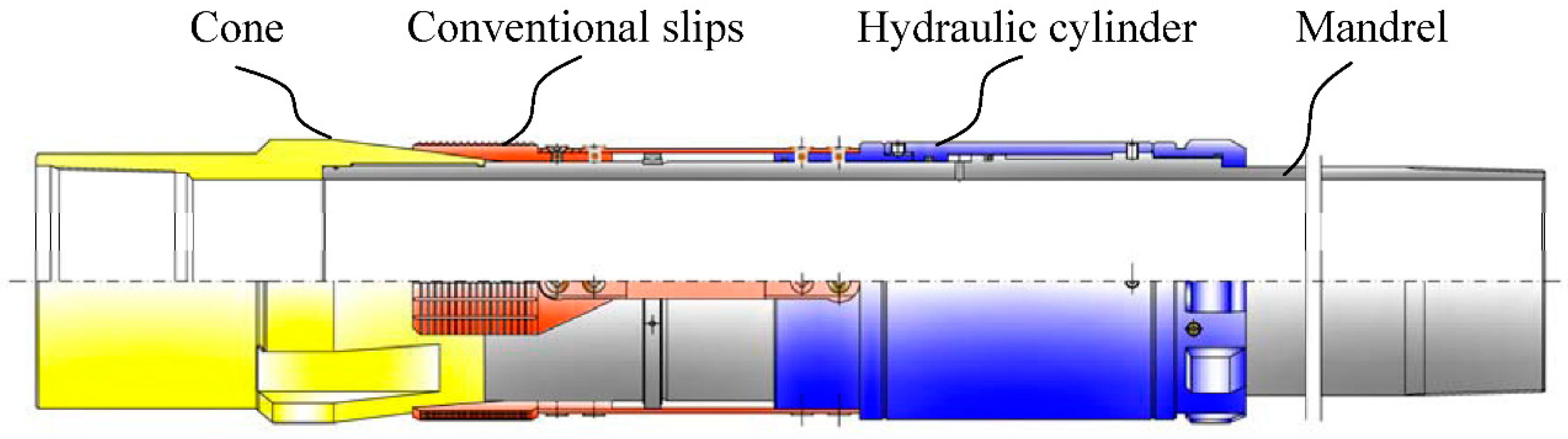
The conventional liner hanger can be set by engaging the slip and cone (
Figure 1) [
11,
12,
13,
14]. Basic conventional liner hanger has slips with teeth and tapped bottom by acting as a wedge. The slips will distribute the liner weight evenly on the tapered swivel cone. The teeth have hardness greater than the casing wall to penetrate the casing surface and anchor the liner [
15,
16].
When the slips are set and reach up to the inner wall of casing, its working surface produce the pre-tightening force. As the liner is released, the liner weight held by the drilling pipe is transferred to the liner hanger during the liner setting process. The liner weight forces the slips to move downward and imposes a radial and expansive force on the inner wall of the casing, and then the slip teeth can bite into casing with dents left [
17,
18]. Finally, the liner weight is fully supported by liner hanger which is set by engaging slip and cone in conventional version [
19,
20].
Failure of liner hanger and casing is often responsible for well control incidents [
21,
22,
23,
24]. The penetration depth of slip teeth depends on the penetration force and plays a crucial role in setting liner hanger. Under a small penetration force, the slips cannot hold the casing due to the shallow penetration depth. Conversely, the liner weight exerts a much larger force on slips and drives the slips to penetrate deeper into the casing wall, leaving a permanent damage [
25,
26].
The outer diameter of liner hangers is normally close to the casing drift diameter. The convention slips are installed on the cone body without any protection, and they are accidentally impacted by fraction and debris during running the liner into the hole [
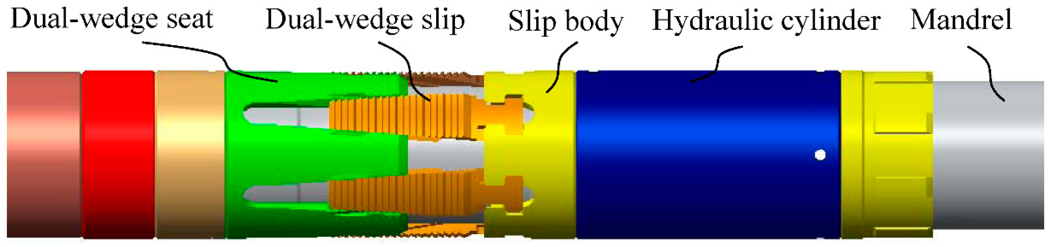
27]. The novel liner hanger systems with special slips are designed to reduce the risks of the premature setting related to the conventional liner hangers, and the dual-wedge slips type liner hanger with high reliability is among those hanger systems. The geometry of dual-wedge slips is different to conventional ones, and the guide rails instead of cones are used to redirect the slips [
28,
29] (
Figure 2). The longitudinal fluid bypass channels between the dual-wedge slips and the mandrel increase the annular flow area, and the pressure loss and the risk of lost circulation can be reduced.
How to calculate the maximum hanging weight of liner hanger is important for casing and liner string design. The slips of liner hanger work as anchors in the casing wall. Once the liner hanger fails or fractures, the whole line string with a length of thousands of meters will lose its support and fall into the bottom of well, which will seriously affect wellbore stability and drilling safety. To solve the reliability problem of slip after hanging of the liner string, the current methods are mainly based on empirical formulas and experiments. The reliability problem of slip mainly depends on the penetrate force and the depth. Compared to conventional slips, the design and manufacture of dual-wedge shaped slips are very difficult, so they do not widely be used in cementing. Few researchers carried out some research about the force transfer mechanism of dual-wedge shaped slips for Liner Hanger, and there is no method to predict the penetration force of the special slips.
2. Theoretical Study on Force Transfer Characteristics of Hanging Mechanism
2.1. Mechanical Model of Conventional Slips and Cone
The liner hanger features slips that lands into the con seat to suspend the liner weight. The conventional slip has a tapped bottom (
Figure 3). The load is carried by the top and bottom surfaces, which are the operating surfaces. The conventional slip has a non-uniform thickness and a uniform width, which is an axisymmetric body under the action of axisymmetric force, and the spatial problem is considered as an axisymmetric one [
30,
31,
32,
33]. Forces generated by the hanging mechanism and acting on the slips are shown in
Figure 3.
The penetration force
P between the casing and convention slips can be calculated as follows [
34,
35]:
where
WL is the liner weight,
n is the slip number,
θ is taper of slips and hanger angle,
φ is the friction angle.
2.2. Mechanical Model of Dual-Wedge Slips and Slip-Seat
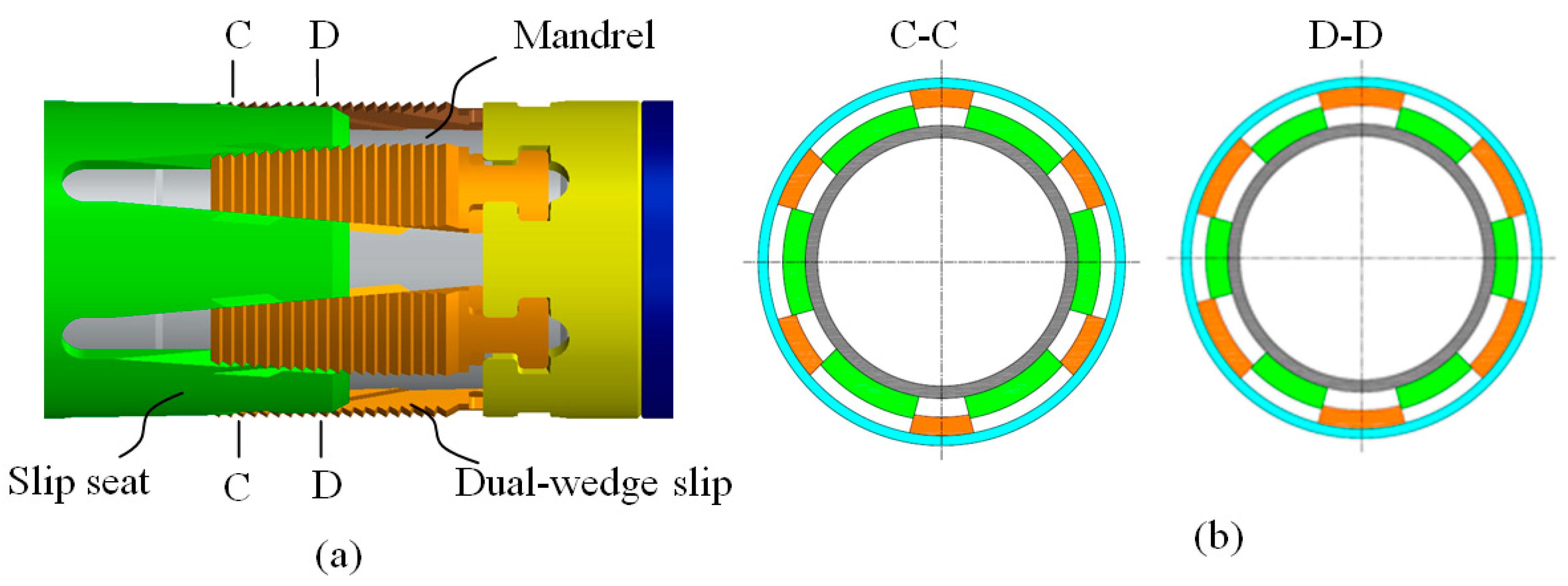
The dual-wedge slips are mechanically contained under the tool outer diameter and protected in the slip seat. Since, as already noted, the main objective of this work is to study the surface configurations and force transfer mechanism of dual-wedge shaped slips. The dual-wedge slip has a uniform thickness and a non-uniform width (
Figure 4). The load is carried by the sides of dual-wedge slip. Both camping surfaces of slip and slip-seat press each other, and the axial force is transferred to the radial force.
After the liner hanger is set, the loading force changes from the axial force (liner weight) to the radial force (penetration force) acted on the slips that penetrate into inner wall of the casing with an opposite force. The dual-wedge slip is not an axisymmetric body, and it is difficult to predict the penetration force due to the complex shape of slips. The calculation of penetration force for dual-wedge slip is three dimensional problems. The object of this study is to obtain an analytical solution to the mathematical model and calculate the penetration force of dual-wedge slips under different liner weights.
The geometry shape of slips and slip-seat is complicated, and the ineffective geometry factors unrelated to load transfer such as slip teeth and guide rails (tongue and groove) are ignored. The structure of dual-wedge slips hanging mechanism is illustrated in
Figure 5.
2.2.1. Main Geometrical Parameters and Force Analysis
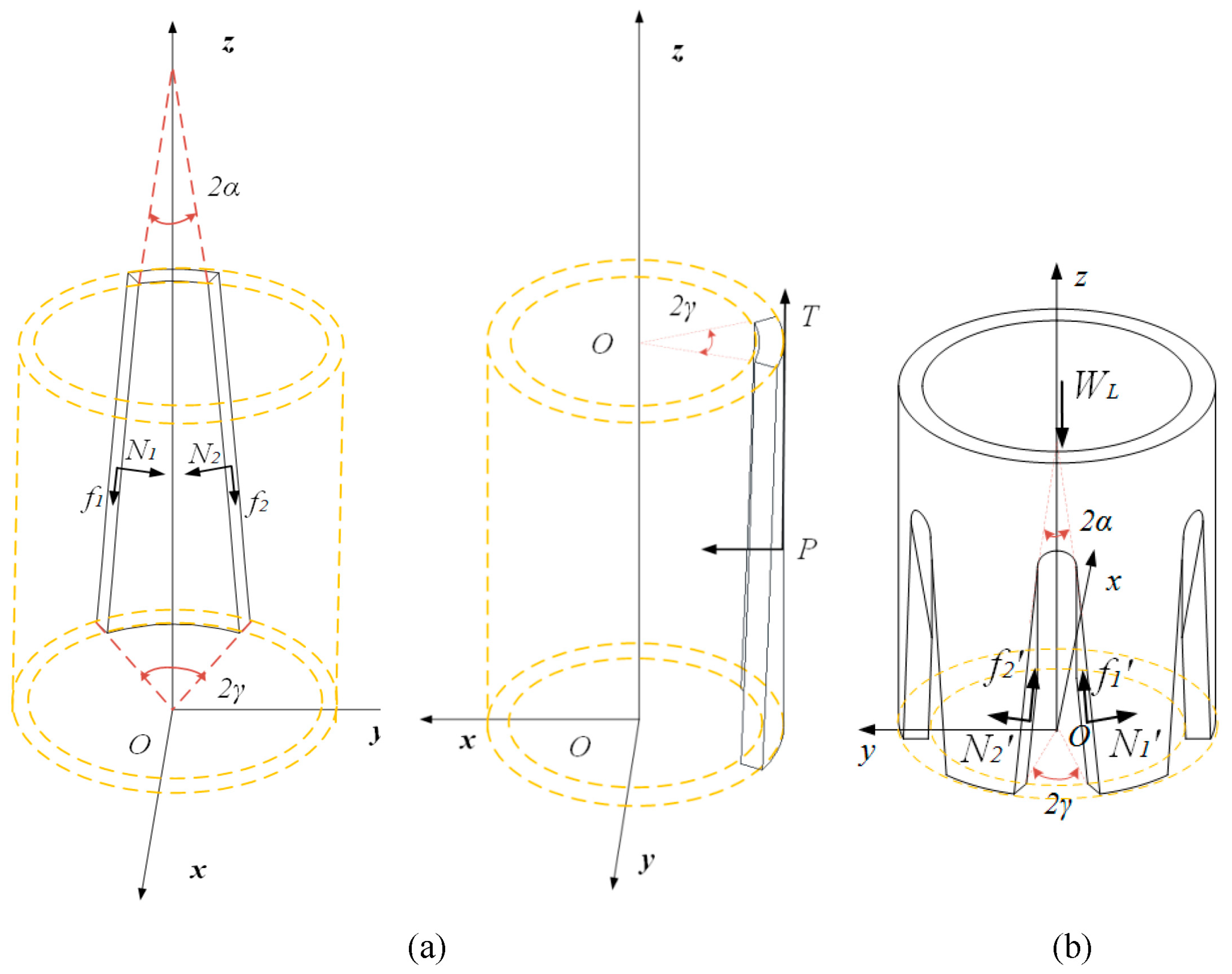
Compared to conventional slips, the dual-wedge slips are difficult to be designed and manufactured. In order to study the mechanical properties of the moving pair composed of dual-wedge slip and slip-seat, a coordinate system is established to describe their geometric parameters, motion, and contact, as shown in
Figure 5.
The wedge sides of slip and slip-seat are rotated on the XZ plane. They can also be manufactured with the milling cutter rotation by numerically controlling the milling machine. The inclined plane can be considered as the Eulerian angle α, β, and γ about the x, y, and z axes respectively.
Combining with the geometric parameters of slips and slip-seat, the force transfer model and interaction between slip and slip-seat can be analyzed through transformation of coordinates with the matrix method. The force of slips and slip-seat was analyzed respectively (
Figure 5). Six forces acted on each slip:
f1 and
f2 are the friction forces that acted on the wedge faces of the slip;
N1 and
N2 are the normal forces that acted on the wedge faces of the slip;
N is the radial force that acted on the top face of the slip by casing;
P is the penetration force of the slip;
T is the axial force that acted on the top face of slip by casing;
WL is the weight of liner.
2.2.2. Force Vectors and Rotation Matrix Multiplication
The slip and slip-seat are plane-symmetric, and the two ramped surface are inclined at equal angles and in the opposite direction.
The force vectors acting on the wedge sides are described through real orthogonal 3 × 3 rotation matrix multiplication applied to the basis vectors (1, 0, 0), (0, 1, 0), and (0, 0, 1) followed by translation movement commonly parameterized by Eulerian angle
α and
γ. The matrix can be decomposed as follow:
The normal force vectors on contact surfaces are calculated as follows:
The frictional force vectors are calculated as follows:
The normal force and friction force acted on the wedge faces are equal in magnitude:
In the axial direction, the magnitude of support force acted on each slip can be expressed as:
2.2.3. Static Equilibrium
The dual-wedge slip is under the equilibrium condition. The forces acting on the slips are balanced, and they are expressed as
In the axial direction, the mechanical equilibrium relationship is expressed as follows:
In the radial direction, all forces are projected and balanced to obtain the following formula:
The formula calculating the penetration force can be derived by integrating Equations (7)–(15):
where
P is the penetration force,
WL is the liner weight,
n is the slip number,
α is Eulerian angle about the
x axe,
γ is Eulerian angle about the
z axe, and
μ is the friction coefficient.
3. Numerical Simulation of Interaction between Dual-Wedge Slips and Casing
3.1. Finite Element Model
The interaction and strength analysis for hanging system are carried out based on finite element method. ABAQUS 6.14 software was used to conduct numerical simulation of the dual-wedge slip hanger assembly. The ineffective geometry factors unrelated to load transfer such as slip teeth and guide rails (tongue and groove) are ignored, and finite element model for the dual-wedge slip hanger assembly was established in
Figure 6. The finite element mesh was formed by ABAQUS-C3D8R (Eight-node brick element with reduced integration) which has better convergence and accuracy for the contact problems.
The type of constraint between slip and casing was Contact, which was the same as that in the theoretical study.
The geometric parameters of hanging mechanism are listed in
Table 1. The material of liner hanger system is ASME A193 B2 alloy steel (Chinese designation: 35CrMo). To describe the mechanical behavior of the hanging mechanism, we used an elastic material model, and mechanical parameters are listed in
Table 2.
3.2. Simulation Results
The strength of hanging mechanism under different axial load is calculated with the finite element (FE) method. The von Mises stress distribution of hanging system under the liner weight (axial load) of 1000 kN and the friction coefficient of steel to steel surfaces in drilling mud 0.1 is shown in
Figure 7.
The distribution of von-mises stress can evaluate the safety of the hanging mechanism. It shows that the stress of slip hanger assembly is basically within the elastic range, and the maximum stress of slip-seat is 591.6 MPa. The FE analysis also reveals an uneven stress distribution on the inner wall of the casing under the contact force. The hanging system including slips and slip-seat and the upper casing can withstand the weight of the liner hanging. The radial slip/casing load is circumferentially distributed by the slip to the seat. And stress of the inner face is lower than outer surface of the seat, which shows this type of hanger loading protects the liner pipe from collapse loads.
The radial penetration force and depth of slip to casing is also an important parameter to the capacity of liner hanger, which depends on the contact force between slip and casing. The contact forces can be obtained from the contact pairs in the ABAQUS/Standard data, as shown in
Table 3. The contact loads from the theoretical calculation and numerical simulation are compared, as shown in
Figure 8.
According to
Figure 8, the results from numerical simulation are comparable with those calculated in Equation (16). This confirms the validity of the formula proposed in this study and the formula is applicable in predicting the slip penetration forces under different liner weights.
4. Experimental Research
The tensile load due to the liner weight and the load from the pressure in the liner are the main loads of the hanger. In order to verify the theoretical model and investigate the force transfer mechanism of dual-wedge shaped slips liner hanger, the tensile experiment was carried out. The contact force and stress between slip and casing is difficult to obtain directly, but it can be calculated indirectly by the circumferential stress of the casing outer surface. Strain gauges were placed on the contact area of casing outer surface.
4.1. Experimental Setup and Equipment
The tests were carried out by using the equipment in
Figure 9. The test machine is displacement-controlled and mainly consists of the horizontal hydraulic loading system for axial load and the liner hanger system. The load of hydraulic jacks can reach up to 5000 kN.
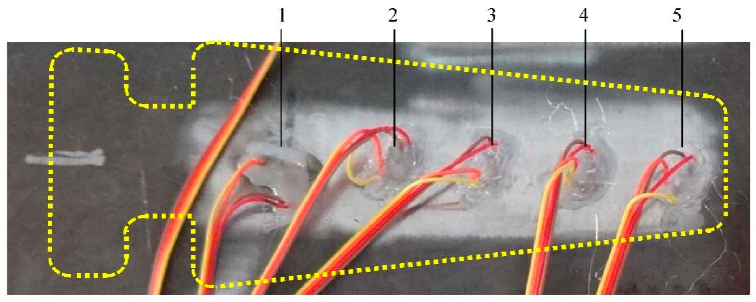
More stress-monitoring points will get more data and better results, but the number of stress-monitoring points is limited to the size of strain gauges and data collection channels. Five pairs of strain gauges were attached to contact area of casing outer surface along the axial direction in
Figure 10.
4.2. Experimental Results
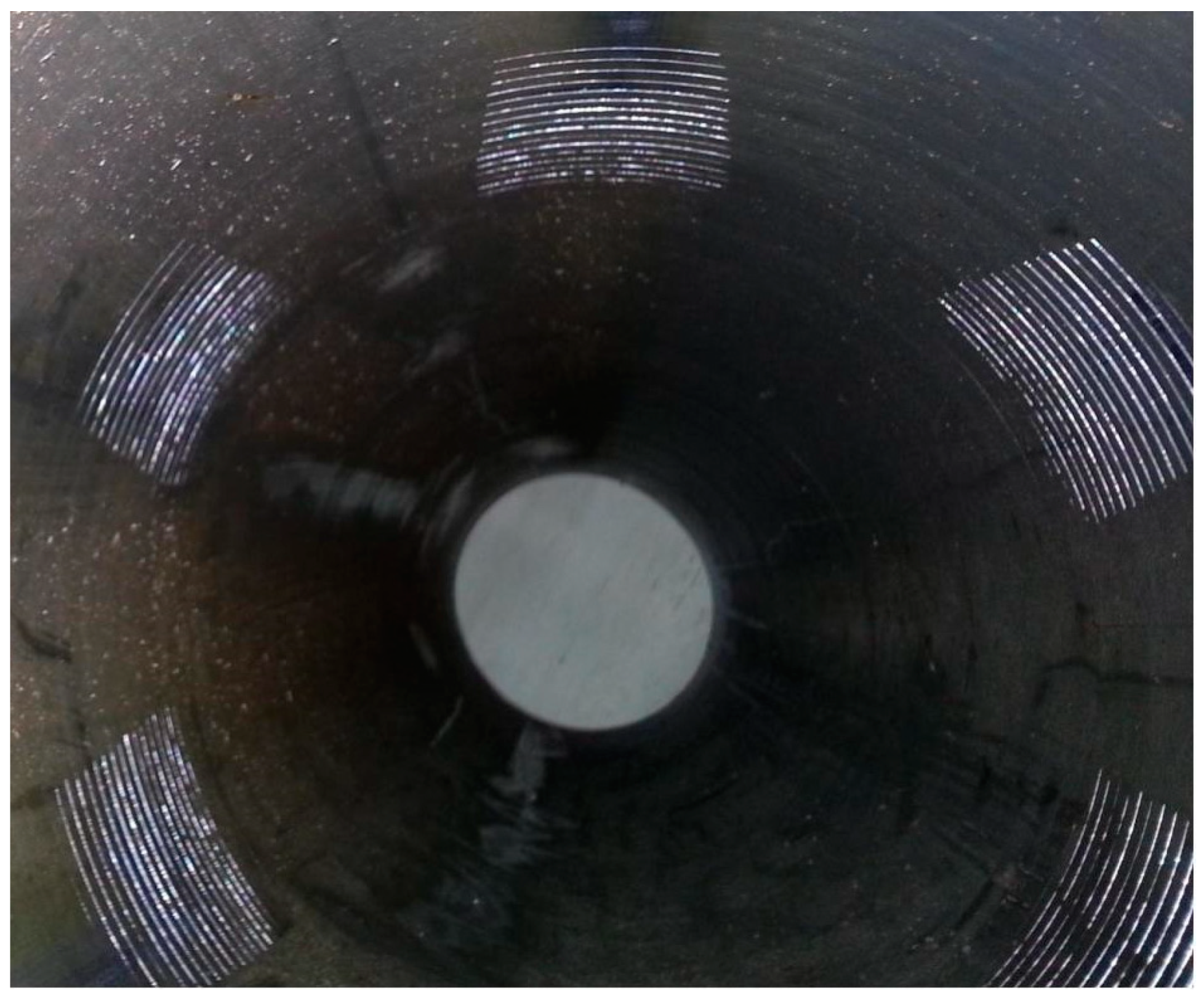
After the hanger was set up, axial tension loads of 500 kN, 1000 kN, 1500 kN, 2000 kN were applied by the tensile testing machine. The axial load exerts a radial force on slips, which drives the slips to penetrate into the casing wall, and leaving dents, which are shown in
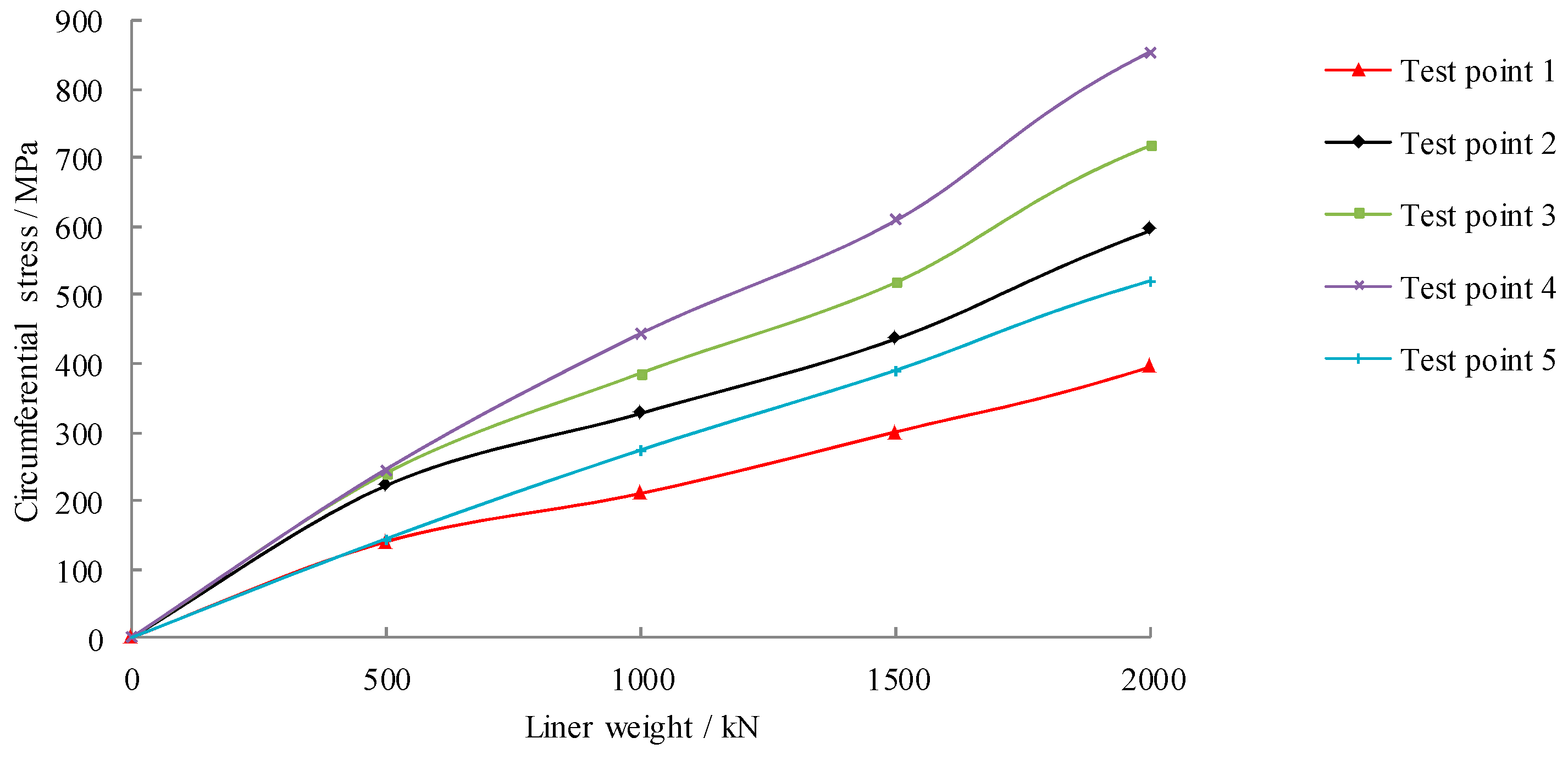
Figure 11. The circumferential strains of the casing outer surface were collected in
Figure 12.
It shows that liner hanger worked well, and six dual-wedge slips all penetrated into the inner wall of casing. It can be assumed that the tensional load has transferred uniformly from the slip-seat to every slip, based on which we carry out further calculation.
The stress is directly proportional to the liner weight (
Figure 12), and the stress increases with an increase in the tension load. The penetration force of slips leads to an uneven stress distribution on the contact area. The stress on points 1 and 5 is lower than that on other points, which indicates that it has higher circumferential stress in the middle area and lower circumferential stress in both ends along the axial direction, which are also consistent with the numerical simulation in
Figure 7.
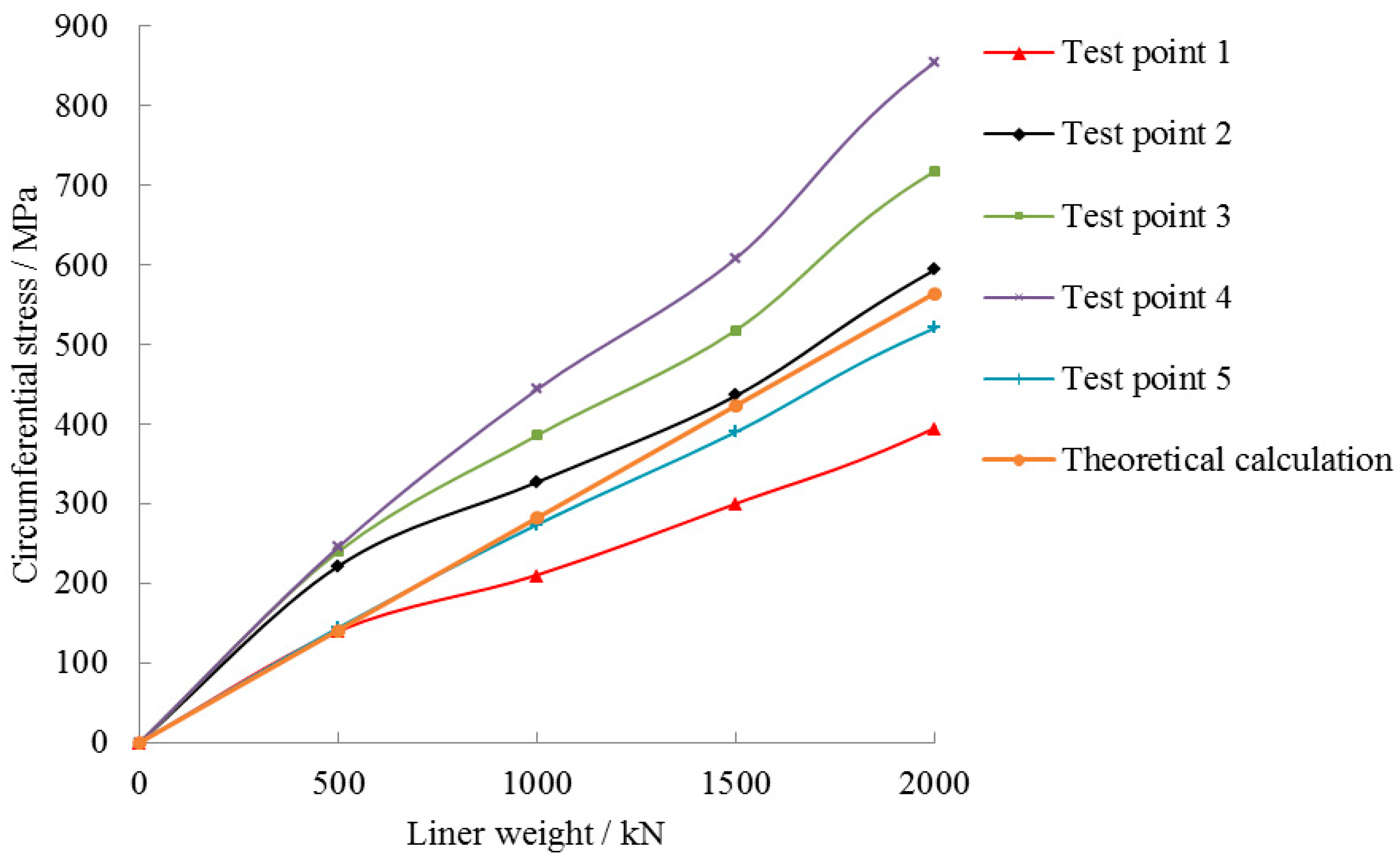
4.3. Comparison of Theoretical Calculation and Test Results
It is assumed that the contact load (penetration force) is uniformly distributed over the inner face of contact area between the slips and casing. The average contact stress between dual-wedge slips and casing can be written as:
where
q is the average contact stress,
P is contact load (penetration force) between slip and casing,
S is the contact area between slip and casing.
The circumferential stress components of casing outer wall can be calculated with Lame formula.
where
θφ is the circumferential stress,
a is the inner diameter of casing,
b is the outer diameter of casing,
q is the average contact stress.
The results of theoretical calculation and test are compared as
Figure 13.
It shows that the calculated value well coincide with the measured mean values, which can verify the accuracy of the theoretical model for predicting the penetration force of the dual-wedge slip.
5. Discussion
5.1. Effects of Geometrical Parameters on the Slip Penetration Force
Equation (16) shows that the penetration force P depends on several parameters such as geometric parameters α and γ and liner weight WL and friction coefficient μ. In order to study the effects of several parameters on the penetration force P, the control variate method was introduced.
5.1.1. Eulerian Angle α
The liner weight
WL, the second Eulerian angle
γ, and friction coefficient
μ are considered as constants, the relationship between the penetration force
P and the first Eulerian angle
α is expressed as Equation (19), and the curve is shown in
Figure 14.
Figure 14 shows the penetration force P decreases with an increase in the first Eulerian angle α, and it decreases significantly within the range of 0–30°. The slope of the function curves is also affected by the Eulerian angle γ. The Eulerian angle α has significant influences on the penetration force when the first Eulerian angle α is less than 60°, and has less significant effects when the first Eulerian angle α is higher than 60°.
5.1.2. Eulerian Angle γ
The liner weight
WL, the first Eulerian angle
α, and friction coefficient
μ are considered as constants, and the relationship between the penetration force
P and the second Eulerian angle
γ is expressed as Equation (20), and the curve is shown in
Figure 15.
The penetration force P is a sinusoidal function of the second Eulerian angle γ, and the penetration force P increases with an increase in γ. The slope of the sinusoidal function curves are affected by the Eulerian angle α. The second Eulerian angle γ has significant influences on the penetration force when the first Eulerian angle α is less than 30°, and has less significant effects when the first Eulerian angle α is higher than 30°.
It can be seen from
Figure 14 and
Figure 15 that the slips and slip-seats can be designed by changing the geometry of the slip edges to adjust the penetration force.
5.2. Effects of Friction Coefficient on the Slip Penetration Force
The liner weight
WL, the Eulerian angle
α and
γ are considered as constants, and the relationship between the penetration force
P and the friction coefficient
μ is expressed as Equation (21), and the curve is shown in
Figure 16.
The penetration force P decreases with an increase in the friction coefficient μ, and it decreases significantly within the range of 0–0.1. The friction coefficient μ can also affect the penetration force during the liner hanger setting process, and the friction coefficient can be changed by changing the surface roughness during design and manufacturing processes. Adding a friction reducer to the slip seat also can be a good design to provide a smoother slip ride along the slip seat.
5.3. Effect of Liner Weight WL
The Eulerian angle
α,
γ and friction coefficient
μ are considered as a constant, and the relationship between the penetration force
P and liner weight
WL can be expressed as:
According to Equation (22) and
Figure 17, it shows the positive correlation between the penetration force
P and the liner weight
WL. As the liner weight increases, the penetration force of the slips increases, and the slips are inserted deeper into the inner wall of the upper casing. When the light liner is tripped into the borehole, the weight is insufficient to achieve the action of slips, and a pre-determined minimum gripping force must be applied to avoid slippage of liner.
6. Conclusions
This study presents the analytical solution to the mathematical model to explain the force transfer mechanism of dual-wedge slips for liner hanger. Numerical simulation and experimental study were carried out to verify the mathematical model. The conclusions are obtained as follows:
- (1)
The formula of calculating the penetration force for dual-wedge slip was presented. The formula shows that the penetration force is affected by several parameters such as geometric parameters α and γ, liner weight WL and friction coefficient μ.
- (2)
The penetration force of dual-wedge slips increases with an increase in the liner weight and Eulerian angle γ, and it decreases with an increase in Eulerian angle α and friction coefficient. The sensitive range of Eulerian angle α is (0, 30), and the sensitive range of Eulerian angle γ is (0, 60). The geometric parameters of the dual-wedge slip can be designed to obtain an optimal penetration force, and ensure that the slip teeth penetrate into the inner wall of casing without any damage to the casing.
- (3)
The simulation and experimental results demonstrate that the penetration force leads to an uneven stress distribution on the casing. By optimizing the bearing surface of dual-wedge slip and seat, the radial slip/casing load can be circumferentially distributed by the slip to the seat with minimal stress concentration, and this protect the liner pipe and hanger mandrel from collapse loads.
The research about the force transfer mechanism for liner hanger is based on linear elastic material models. The formula cannot apply to elastic–plastic materials, and the collapse model of casing under large penetration force is not clear, which needs to be further studied in the future.
Author Contributions
F.H.: theoretical study, experimentation, conceptualization; data curation; analysis, original draft; H.H.: numerical simulation; P.Z.: original draft; Y.Z.: analysis, original draft; J.H.: reviewing/editing the draft; L.X.: conceptualization, supervision, writing—reviewing and editing. All authors have read and agreed to the published version of the manuscript.
Funding
This research was funded by [Beijing Science and Technology Plan Project] grant number [KM202010017004] and [National Key Research and Development Program of China] grant number [2022YFB4701105].
Institutional Review Board Statement
The study did not require ethical approval.
Informed Consent Statement
The study did not involve humans.
Acknowledgments
The authors are grateful for financial support from the Beijing Science and Technology Plan Project (No. KM202010017004) and National Key Research and Development Program of China (No. 2022YFB4701105).
Conflicts of Interest
The authors declare that they have no competing financial interests or personal relationships that could appear to influence the work reported in this paper.
References
- API SPEC 19LH; Liner Hanger Equipment. 1st ed. API: Washington, DC, USA, 2019.
- API STD 65-Part 2; Standard for Isolating Potential Flow Zones during Well Construction. 2nd ed. API: Washington, DC, USA, 2010.
- Ramadan, M.A.; Salehi, S.; Ezeakacha, C.; Teodoriu, C. Analytical and experimental investigation of the critical length in casing–liner overlap. Sustainability 2019, 11, 6861. [Google Scholar] [CrossRef] [Green Version]
- Ahmed, S.; Patel, H.; Salehi, S. Effects of wait on cement, setting depth, pipe material, and pressure on performance of liner cement. J. Petrol. Sci. Eng. 2021, 196, 108008. [Google Scholar] [CrossRef]
- Jiminez, C.; Soto, S.; Leon, A.; Batocchio, M.A.P.; Marval, P.; Schoener-Scott, M.F. Case histories—Implementation of new liner hanger technology in south central Venezuela significantly improves operations in complex wells. In Proceedings of the Abu Dhabi International Petroleum Exhibition and Conference, Abu Dhabi, United Arab Emirates, 3–6 November 2008. [Google Scholar]
- Berge, T.; Mathisen, K.D.; Storebø, O.; Muir, M. Expandable liner hanger milling: North Sea case histories. In Proceedings of the SPE/IADC Drilling Conference, Amsterdam, The Netherlands, 5–7 March 2013. [Google Scholar]
- Zhong, A.; Moeller, D.; Maddux, S. Development of a high hang weight expandable liner hanger for deepwater applications. In Proceedings of the Offshore Technology Conference, Houston, TX, USA, 1–4 May 2017. [Google Scholar]
- Ahmed, S.; Salehi, S.; Ezeakacha, C.P.; Teodoriu, C. Evaluation of liner hanger seal assembly and cement sheath as a dual barrier system: Implications for industry standards. J. Petrol. Sci. Eng. 2019, 178, 1092–1103. [Google Scholar] [CrossRef]
- Kelsey, M.; Stautzenberger, A.; Einervoll, O.; Dietz, W.; Lajesic, B.; Stokes, M. Multilateral expandable metal anchoring packer design, development, and application in the North Sea. In Proceedings of the Offshore Technology Conference, Houston, TX, USA, 4–7 May 2020. [Google Scholar]
- Stolyarov, S.; Bagci, S.; Gomez, R.; Wright, B.; Yang, J. Application of cemented multi-entry frac sleeves in multistage stimulation: A case study. In Proceedings of the SPE Russian Petroleum Technology Conference, Virtual, 26–29 October 2020. [Google Scholar]
- Walvekar, T.; Jackson, A.T. Expandable technology improves reliability of conventional liner hanger systems. In Proceedings of the IADC/SPE Drilling Conference, Miami, FL, USA, 21–23 February 2006. [Google Scholar]
- Walvekar, S.; Jackson, T. Development of an expandable liner-hanger system to improve reliability of liner installations. In Proceedings of the Offshore Technology Conference, Houston, TX, USA, 30 April–3 May 2007. [Google Scholar]
- Patel, H.; Salehi, S.; Teodoriu, C.; Ahmed, R. Performance evaluation and parametric study of elastomer seal in conventional hanger assembly. J. Petrol. Sci. Eng. 2019, 175, 246–254. [Google Scholar] [CrossRef]
- Ahmed, S.; Patel, H.; Salehi, S. Numerical modeling and experimental study of elastomer seal assembly in downhole wellbore equipment: Effect of material and chemical swelling. Polym. Test. 2020, 89, 106608. [Google Scholar] [CrossRef]
- Cai, M.J.; Cao, Y.P.; Wang, X. Analysis of interaction between HTHP completion packer’s slip and the Casing Wall. Appl. Mech. Mater. 2013, 423–426, 866–870. [Google Scholar] [CrossRef]
- Royer, E.S.; Turney, R.A. HPHT expandable liner hanger technology with superior pressure integrity. In Proceedings of the Offshore Technology Conference, Houston, TX, USA, 6–9 May 2019. [Google Scholar]
- Cao, Y.; Tong, S.; Dou, Y. Analysis of limit setting force of casing inside slips based on cylindrical shell theory. Open Mech. Eng. J. 2014, 8, 234–237. [Google Scholar] [CrossRef] [Green Version]
- Byrom, T.G. Casing and Liners for Drilling and Completion, 2nd ed.; Gulf Professional Publishing: Houston, TX, USA, 2014. [Google Scholar]
- Patel, H.; Salehi, S. Comparative evaluation of elastomer seal energization in conventional and expandable hanger assembly. In Proceedings of the ASME 2019 38th International Conference on Ocean, Offshore and Arctic Engineering, Glasgow, Scotland, UK, 9–14 June 2019. [Google Scholar]
- Ahmed, S.; Salehi, S.; Ezeakacha, C. Review of gas migration and wellbore leakage in liner hanger dual barrier system: Challenges and implications for industry. J. Nat. Gas Sci. Eng. 2020, 78, 103284. [Google Scholar] [CrossRef]
- Munshi, A.A.; O’Connor, K.; McMahon, S.; Carmody, M. Development of a remotely activated liner hanger system while minimizing operational risks. In Proceedings of the SPE/IATMI Asia Pacific Oil & Gas Conference and Exhibition, Jakarta, Indonesia, 17–19 October 2017. [Google Scholar]
- Patel, H.; Salehi, S. Development of an advanced finite element model and parametric study to evaluate cement sheath barrier. J. Energy Resour. Technol. 2019, 141, 092902. [Google Scholar] [CrossRef]
- Zhang, Z.; Sang, P.; Sang, Z.; Hou, D.; Lv, Y.; Zheng, Y.; Zhang, C. Analyzing failure of casing head slip hanger. Eng. Fail. Anal. 2020, 108, 104301. [Google Scholar] [CrossRef]
- Ahmed, S.; Salehi, S. Failure mechanisms of the wellbore mechanical barrier systems: Implications for well integrity. J. Energy Resour. Technol. 2021, 143, 073007. [Google Scholar] [CrossRef]
- Robinson, S.; Littleford, T.; Luu, T.; Wardynski, K.; Evans, A.; Horton, B.; Oman, M. Acoustic imaging of perforation erosion in hydraulically fractured wells for optimizing cluster efficiency. In Proceedings of the SPE Hydraulic Fracturing Technology Conference and Exhibition, The Woodlands, TX, USA, 4–6 February 2020. [Google Scholar]
- Stolyarov, S.; Casanova, G.; Xu, Y.Q.; Deng, G.; Holmes, K.; Gomez, R.; Young, A. How much can you afford to ignore casing failure during hydraulic fracturing the search for a non-damaging frac-plug. In Proceedings of the SPE Annual Technical Conference and Exhibition, Virtual, 26–29 October 2020. [Google Scholar]
- Tang, X.; Qian, B.; Li, B.; Liu, Y.; Zhang, Y. Development and application of a packer-type drilling-free liner hanger. Nat. Gas Ind. B 2014, 1, 125–128. [Google Scholar] [CrossRef] [Green Version]
- Fay, P. Embedded Flex-Lock Slip Liner Hanger. U.S. Patent 2006/0278404 A1, 14 December 2006. [Google Scholar]
- Mohamed, A.O.; Al-Zuraigi, A. Liner hangers technology advancement and challenges. In Proceedings of the SPE Middle East Oil and Gas Show and Conference, Manama, Bahrain, 10–13 March 2013. [Google Scholar]
- Dou, Y.; Pan, H.; Tong, S.; Cao, Y.; Gao, W. Study on the interaction mechanism of packer slips and thick wall casing. Open Mech. Eng. J. 2014, 8, 230–233. [Google Scholar] [CrossRef] [Green Version]
- Sinha, P.; Ranjan, A.; Srivastava, P.; Doodraj, S.; Lang, C. Unitized wellheads for rajasthan onshore development drilling—Proven safer and economical wellhead design compared to bowl and slip wellheads. In Proceedings of the IADC/SPE Asia Pacific Drilling Technology Conference, Singapore, 22–24 August 2016. [Google Scholar]
- Tikhonov, V.; Gelfgat, M.; Ring, L.; Bukashkina, O. Refinement of the drillpipe-slip mechanical model. In Proceedings of the SPE Russian Petroleum Technology Conference, Moscow, Russia, 16–18 October 2017. [Google Scholar]
- Liu, Y.; Lian, Z.; Shi, T.; Sang, P. Fracture failure analysis and research on slip of casing head. Eng. Fail. Anal. 2019, 97, 589–604. [Google Scholar] [CrossRef]
- Okstad, E.H.; Sangesland, S. Integrity assessment of well barriers threatened by increasing casing hanger loads. SPE Drill. Completion 2009, 24, 286–292. [Google Scholar]
- Zhang, L.; Zhang, L.; Liang, W. Casing safety evaluation for setting liner hanger. J. Nat. Gas Sci. Eng. 2014, 19, 58–61. [Google Scholar] [CrossRef]
Figure 1.
Conventional liner hanger.
Figure 1.
Conventional liner hanger.
Figure 2.
Liner hanger with dual-wedge slips.
Figure 2.
Liner hanger with dual-wedge slips.
Figure 3.
Conventional liner hanger profile. (a) Prototype model of slips and cone; (b) the forces acted on the slip.
Figure 3.
Conventional liner hanger profile. (a) Prototype model of slips and cone; (b) the forces acted on the slip.
Figure 4.
Concept of hanging mechanism with dual-wedge slips. (a) 3-D CAD model; (b) cross sectional view.
Figure 4.
Concept of hanging mechanism with dual-wedge slips. (a) 3-D CAD model; (b) cross sectional view.
Figure 5.
Mechanical model and main geometrical parameters of (a) slip and (b) slip-seat.
Figure 5.
Mechanical model and main geometrical parameters of (a) slip and (b) slip-seat.
Figure 6.
Finite element model of hanging mechanism. (a) Assembly; (b) part; (c) mesh.
Figure 6.
Finite element model of hanging mechanism. (a) Assembly; (b) part; (c) mesh.
Figure 7.
Von-Mises stress distribution of (a) casing, (b) slip, and (c) slip-seat.
Figure 7.
Von-Mises stress distribution of (a) casing, (b) slip, and (c) slip-seat.
Figure 8.
Comparison of results from theoretical calculation and numerical simulation.
Figure 8.
Comparison of results from theoretical calculation and numerical simulation.
Figure 9.
Experimental setup for liner hanger test. (a) Test device schematic diagram; (b) the liner hanger; (c) machine used to conduct the experiments.
Figure 9.
Experimental setup for liner hanger test. (a) Test device schematic diagram; (b) the liner hanger; (c) machine used to conduct the experiments.
Figure 10.
Strain gauges location.
Figure 10.
Strain gauges location.
Figure 11.
Leaving dents.
Figure 11.
Leaving dents.
Figure 12.
Circumferential stress of outer casing under liner weight.
Figure 12.
Circumferential stress of outer casing under liner weight.
Figure 13.
Comparison of theoretical calculation and test results.
Figure 13.
Comparison of theoretical calculation and test results.
Figure 14.
Relationship between the penetration force P and Eulerian angle α.
Figure 14.
Relationship between the penetration force P and Eulerian angle α.
Figure 15.
Relationship between the penetration force P and Eulerian angle γ.
Figure 15.
Relationship between the penetration force P and Eulerian angle γ.
Figure 16.
Relationship between the penetration force P and fiction coefficient μ.
Figure 16.
Relationship between the penetration force P and fiction coefficient μ.
Figure 17.
Relationship between penetration force P and liner weight WL.
Figure 17.
Relationship between penetration force P and liner weight WL.
Table 1.
Geometric parameter of hanging mechanism.
Table 1.
Geometric parameter of hanging mechanism.
| Casing | Slip and Slip-Seat |
|---|
Outer Diameter
(mm) | Inner Diameter
(mm) | Eulerian Angle α (°) | Eulerian Angle γ (°) | Contact Area (mm2) |
|---|
| 365 | 337 | 5 | 30 | 1.8e4 |
Table 2.
Mechanical parameters of the material of the hanging mechanism.
Table 2.
Mechanical parameters of the material of the hanging mechanism.
| Density (kg/m3) | Elastic Modulus (GPa) | Poisson’s Ratio | Yield Stress (MPa) | Tensile Strength (MPa) |
|---|
| 7860 | 210 | 0.3 | 835 | 985 |
Table 3.
Contact force between slips and slip-seat under different axial force.
Table 3.
Contact force between slips and slip-seat under different axial force.
| Axial force (kN) | 100 | 200 | 300 | 400 | 500 | 600 | 700 | 800 | 900 | 1000 |
| Contact force (kN) | 265.1 | 530.2 | 795.3 | 1060.4 | 1325.4 | 1590.5 | 1855.6 | 2120.7 | 2385.8 | 2650.9 |
| Disclaimer/Publisher’s Note: The statements, opinions and data contained in all publications are solely those of the individual author(s) and contributor(s) and not of MDPI and/or the editor(s). MDPI and/or the editor(s) disclaim responsibility for any injury to people or property resulting from any ideas, methods, instructions or products referred to in the content. |
© 2023 by the authors. Licensee MDPI, Basel, Switzerland. This article is an open access article distributed under the terms and conditions of the Creative Commons Attribution (CC BY) license (https://creativecommons.org/licenses/by/4.0/).


