Article

Analysis of Cantilever Triple-Layer Piezoelectric Harvester (CTLPH): Non-Resonance Applications

by
Mojtaba Ghodsi
1,*,
Morteza Mohammadzaheri
2 and
Payam Soltani
2
1
School of Energy and Electronic Engineering, University of Portsmouth, Portsmouth PO1 3DJ, UK
2
School of Engineering and the Built Environment, Birmingham City University, Birmingham B4 7XG, UK
*
Author to whom correspondence should be addressed.
Energies 2023, 16(7), 3129; https://doi.org/10.3390/en16073129
Submission received: 6 March 2023 / Revised: 26 March 2023 / Accepted: 28 March 2023 / Published: 29 March 2023

Abstract

:
In this research, a design guideline for a kinetic energy converter using a cantilever triple-layer piezoelectric harvester (CTLPH) for low-frequency applications is presented. By combining the constitutive and internal energy equations, the analytical equations for harvested voltage and power were developed. It was also found that frequency of motion, applied tip force, piezoelectric coefficients, geometrical dimensions, and mechanical properties of layers play significant roles in the performance of the harvester. Having characterised the voltage regulator module, LTC3588, the dependency of output voltage on both the storage and output capacitors of the LTC3588 was investigated. An experimental measurement using the optical method was carried out to determine the applied tip force. Furthermore, the performance of the CTLPH in low frequencies (<3.3 Hz) for various resistive loads was investigated. It was found that both excitation frequency and external resistance load are effective on the maximum generated power. The developed CTLPH shows the optimum power of 17.31 μ W at the external resistance of 20 kΩ, which is highly appropriate for micropower devices with at least 3.2 Hz of kinetic vibration in their environment.

1. Introduction

Research on the creation of micropower generators was recently driven by biomedical implants, the internet of things (IoT), and the monitoring of the health of structures in severe environments [1]. Micro-power-consuming devices of the next generation include CMOS, biomedical implants, and MEMS sensors [2]. Even while high energy density lithium-ion batteries are now reasonably priced to use in the majority of electrical equipment, replacing them can be difficult in specific situations. To address the problem of battery replacement, researchers are working to create self-powered modules using carbon nanotubes [3]. For instance, detecting sensors are essential components to alert about the possibility of fire in inaccessible mountainous areas. It is nearly impossible to replace or recharge the batteries of these sensors due to their remote locations. To address the ever-increasing need for battery power replacement via harvesters, researchers developed various devices to convert environmental energy to electricity via small solar panels, electrostatic, electromagnetic, reverse electrowetting effects [4], and smart materials. However, each system comes with its specific drawbacks. Solar is not suitable for cloudy days or nights, whereas electrostatic is limited by its low-energy density [5]. Most electromagnetic harvesters suffer from bulky coils [6], and reverse electrowetting requires a complex and costly structure [7]. Among smart materials, piezoelectric shows the highest energy density and is used as a harvester, actuator [8,9], sensor [1], and vibration absorber for lightweight structures [10,11,12,13], etc.
Despite high energy density, piezoelectric harvesters suffer from low longevity. The main reason for the short life span is microstructural cracks. It was shown that triple-layer structures could be a potential solution to enhance the output voltage and the life span of piezoelectric harvesters [14]. For example, the effectiveness of energy harvesters in vivo environments, with an excitation frequency of 2 Hz, was demonstrated by coupling the pacemaker’s battery with the harvester. Since the required power of the pacemaker is roughly 30 µW, the array of 100-harvester was helpful to elongate the pacemaker’s longevity by 1.5 years [15]. As another application, Shi proposed an ultra-low frequency (<1.4 Hz) energy harvester floating on the water’s surface using a piezoelectric cantilever beam and generating 6.32 mW [16]. However, no analytical design procedure was proposed for the harvester in this research. Qin et al [17] proposed a branch structure mechanism to apply force to a two-layer piezoelectric harvester to enhance the output voltage. Despite low-frequency excitation, it suffers from a complex structure.
In terms of modelling, Smits et al [18] derived the constitutive equations for piezoelectric bimorph with both series and parallel electrical branch structure mechanisms. DeVoe et al [19] presented a model to predict the static behavior of a cantilever beam made of elastic and piezoelectric layers. However, the matrix inversion used in the presented method complicates the model. Weinburge presented a simpler mathematical model while the effect of the electromechanical coupling coefficient was ignored; it was because of the small value electromechanical coupling coefficient of a maximum of 12% for lead zirconate titanate (PZT) [20]. Wang et al. employed internal energy and constitutive equations to estimate the tip deflection of the cantilever triple-layer actuators with a series of electrical connections of electrodes [21]. The development of new materials with higher electromechanical coupling coefficients (e.g., K31 = 0.38 for PZT-5H) directed Tadmor et al to reform Weinburge and Wang equations by highlighting the effect of large electromechanical coupling coefficients in the equations [22]. Ismail et al corrected the model by considering the geometry of the beam [23]. A model for a multi-layer energy piezoelectric harvester using carbon and glass fibers was developed by Lu et al [24]. However, the analysis of this harvester is based excitation, which is suitable for high-frequency applications.
In this paper, we aim to provide a guideline for designing a low-frequency cantilever triple-layer piezoelectric harvester (CTLPH) with tip excitation and tip mass. Moreover, the piezoelectric layers are electrically connected in parallel. Therefore, in the first step, we will investigate the effective parameters of the output voltage of the energy storage module, which is coupled with the CTLPH. We will find the relationship between the output voltage and applied tip force, the geometrical and electromechanical properties, and the length of the harvester. To verify the derived analytical equations, the tip force will be measured with an optical method using a laser displacement sensor. Finally, the voltage and power of a prototype CTLPH for various resistance loads and frequencies will be measured.

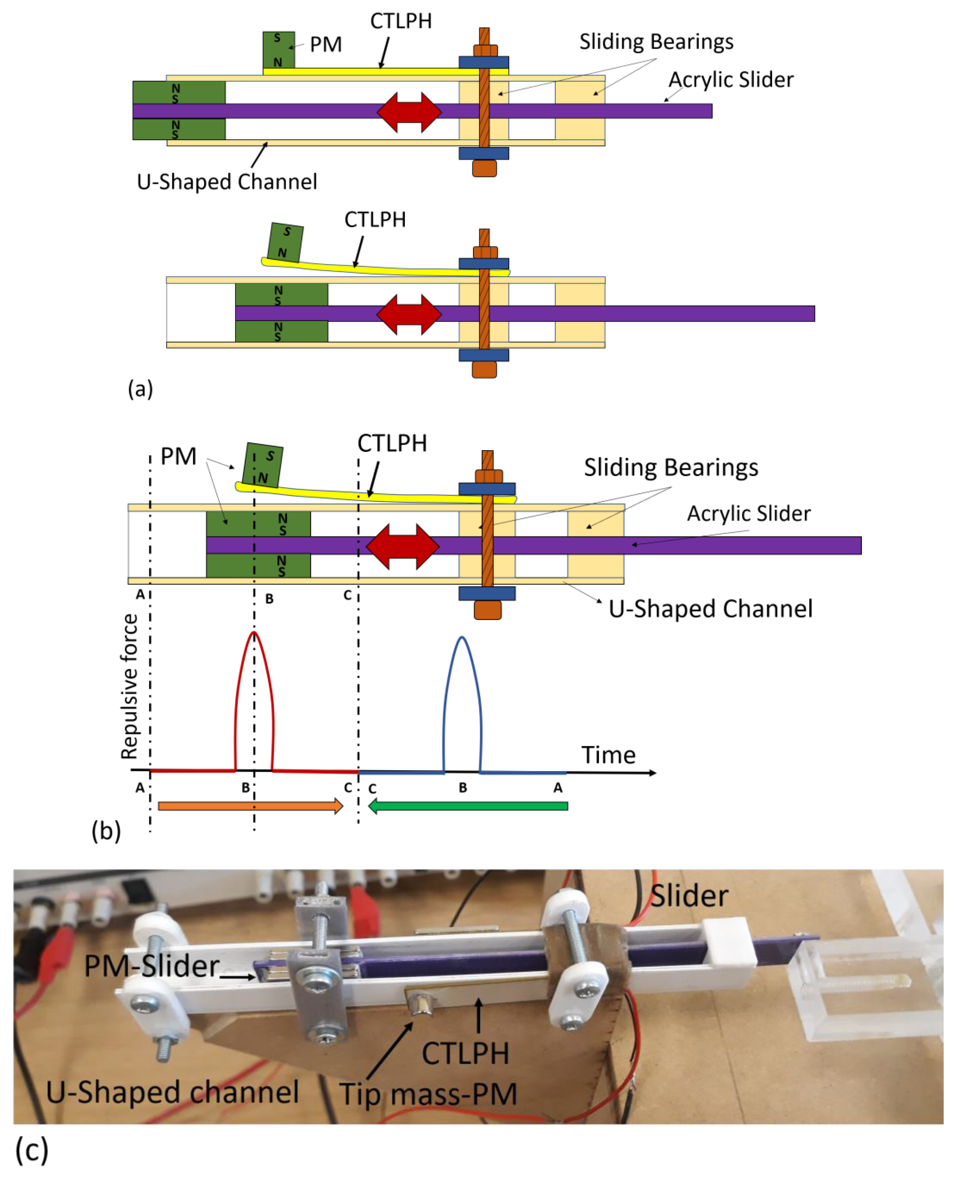
2. Principle of Operation

The schematic structure of the developed energy converter device consists of an active element (i.e., CTLPH), and its excitation mechanism is shown in Figure 1a. The excitation mechanism is an acrylic slider connected to a Scotch yoke to make a reciprocated mechanism. The CTLPH is made of an elastic substrate sandwiched by two piezoelectric layers with a tip mass that is fixed on the wall of a U-shaped acrylic channel. The tip mass of the cantilever beam is a cylindrical permanent magnet (NdFeB-N35, 5 × 5 mm). The slider is made of a permeant magnet bound to an acrylic slider. The directions of the polarity of permanent magnets, on both the slider and CTLPH, are a way that there is a repulsive force between them. The reciprocating motion (Figure 1b) of the slider causes the bending deflection of CTLPH.
This deflection leads to the accumulation of charges on the electrodes and induces a voltage across the electrodes. The real photo of the structure is shown in Figure 1c.

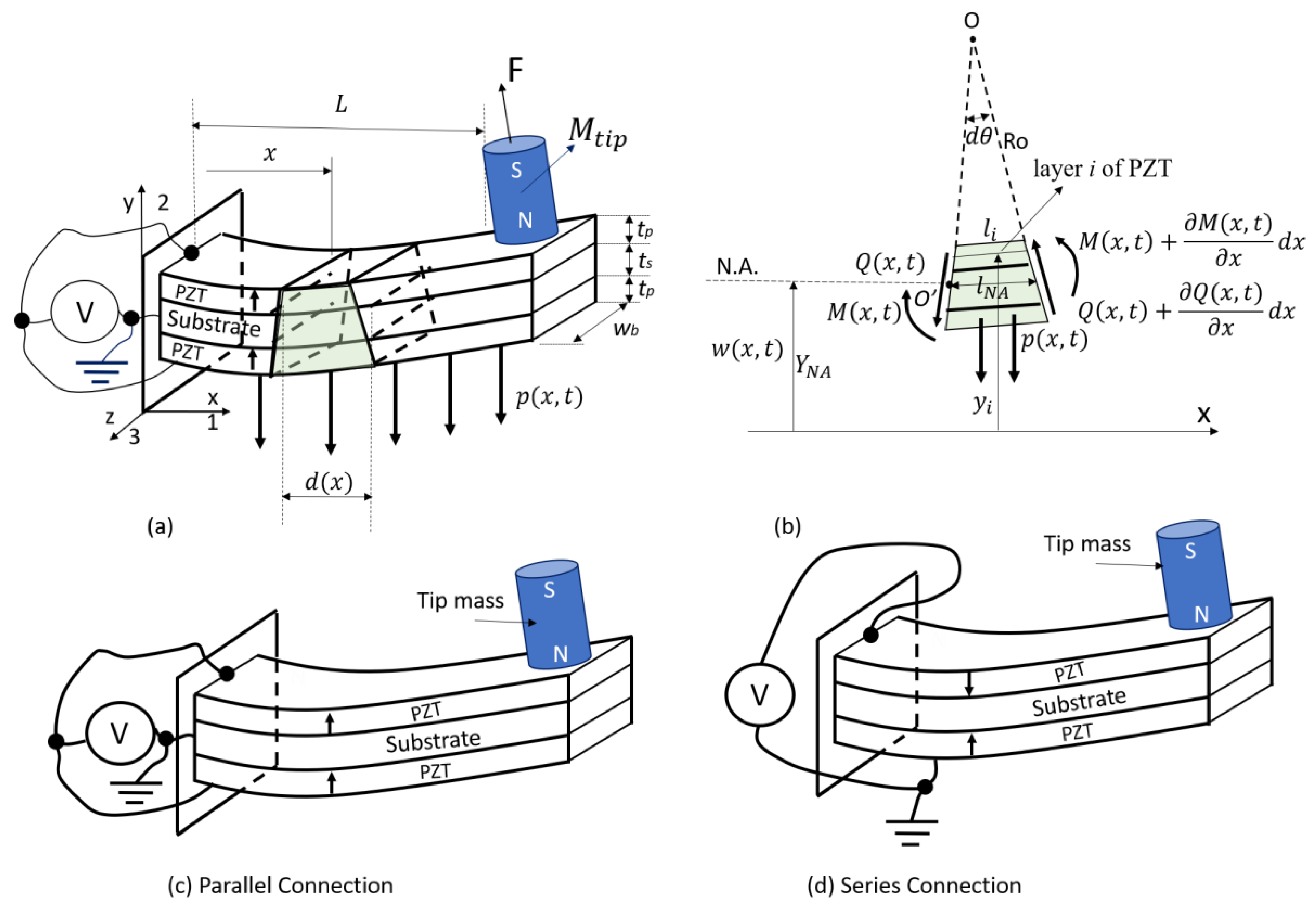
3. Theoretical Analysis

3.1. Assumptions and Constitutive Equations

In this research, a symmetrical cantilever triple-layer piezoelectric harvester with a tip mass was designed, built, and modelled. The CTLPH (Figure 2a) can be modelled by the Euler–Bournoulli beam with effective length (L) and width (Wb). This beam is deformed by a uniformly distributed body force of p(x) and an applied tip force of F . The tip force is caused by a repulsive force between the slider magnet and the tip magnet of the CTLPH. The coordinate system is in a way that x or 1 axis is in the length direction, y or 2 axis is in the width direction, and z or 3 axis is in the thickness direction of the CTLPH. The transverse vibration causes the deflection of w(x,t) in the y-direction. The beam has an arbitrary cross-section, A(x), and is made of three layers of piezoelectric–substrate–piezoelectric. Considering I (x) as the moment of inertia about the z-axis and E(x) as the effective elastic modulus of the triple-layer beam, the bending stiffness of the beam is EI(x). The CTLPH is loaded by a mechanical force that causes a distribution of shear force Q(x,t) and moment M(x,t) along the CTLPH. Figure 2b shows a side view of an infinitesimal element of the CTLPH positioned at x. Based on the selected coordinate system, the tip force and lateral vibration are in the y direction. The central layer is a substrate made of an elastic material with a thickness of ts. The substrate is coated with piezoelectric layers with thickness tp. As with [19,20], we assume that the layers are bonded strongly so that there is no slip between them. Moreover, each part of the CTLPH is in static equilibrium. The radius of curvature (Ro (x)) induced by the applied tip force is much larger than the CTLPH’s thickness, and the cross-section of the CTLPH is constant in a rectangular shape. Figure 2c,d also indicates the different arrangements of the CTLPH in terms of the polarization direction of piezoelectric layers and their electrical connections. The CTLPH is called parallel if the piezoelectric layers are electrically connected, as shown in Figure 2c, and the piezoelectric layers have the same polarization direction. However, if electrical connections are similar to Figure 2d, and the piezoelectric layers have the anti-polarization direction, the CTLPH is called a series. The electrodes of piezoelectric layers are perpendicular to the y direction. Both length (L) and width (Wb) of the CTLPH are much larger than the total thickness (ts + 2tp). If a tip force is applied to the beam, the electromechanical equations for the piezoelectric layers are [18]:
the   upper   layer ,   { e u p = σ u p E u p d 31 E 3                                                                 ( a )   D 3 p = d 31 σ u p + ε 33 σ E 3                                                 ( b ) }
the   lower   layer ,   { e l p = σ l p E l p + d 31 E 3                                                           ( a ) D 3 p = d 31 σ l p + ε 33 σ E 3                                               ( b ) }
where the superscripts p represent the piezoelectric elements, while subscripts u and l indicate the upper and lower layers. The e u p and σ u p are the strain and stress of the lower piezoelectric layer in x or 1 direction, which is along with the length of the CTLPH; d 31 , E u p , and ε 33 σ are transverse piezoelectric coefficient, the elastic modulus of the upper piezoelectric constant electric field, and the permittivity at constant stress, respectively. D 3 p and E 3 are electric displacement and electric field across electrodes in z or 3 direction. The substrate is made of homogeneous elastic material without coupling effect to other fields. Then, the relationship between strain and stress for the substrate can be obtained by Equation (3).
the   substrate   layer ,   e s = σ s   E s   .
where the superscript ‘s’ represents the substrate elastic elements, and e s ,   σ s   and   E s are the strain, stress, and elastic modulus of the substrate layer.

3.2. Bending Stiffness

When a tip force is applied to the CTLPH, it will bend. Due to the strong glue between layers, the positive strain of the lower/upper layer will continuously change to the negative strain in the upper/lower layer. The neutral axis (NA) with zero strain is located in the mid of the substrate layer. Assuming that the coordinate system is coincident with the mid-plane of the substrate, YNA = 0. If the curvature radius of the neutral plane at position x is Ro(x), the strain of the ith piezoelectric layer can be calculated from Equation (4) [25]:
e 1 p = L i L N A L N A = ( R o ( x ) y ) θ R o ( x ) θ R o ( x ) θ = y R o   ( x )   .
The bending moment of the internal stresses of an infinitesimal element in the CTLPH with the length of dx and cross-section of w b d y can be derived by Equation (5).
M = ( t p + t s 2 ) ( t s 2 ) σ l w b y d y t s 2 t s 2 σ s w b y d y t s 2 t p + t s 2 σ u w b y d y   .
Substituting (1b) in (1a) and considering the same piezoelectric material for the upper and lower layers ( E u p = E l p = E p ) , leads to
D 3 p = y E p R o ( x ) d 31 + ( ε 33 σ d 31 2 E p ) E 3   .
By substituting Equation (6) in (1b), the σ u can be obtained from
σ u = y R o ( x ) E p + d 31 E p E 3   .
Similarly, the stress of the lower layer, σ l , can be found in Equation (8):
σ l = y R o ( x ) E p d 31 E p E 3   .
By replacing stress from Equations (3), (7), and (8) in Equation (5), M(x) can be calculated from
M ( x ) = ( t p + t s 2 ) ( t s 2 ) ( y R o ( x ) E p d 31 E p E 3 ) w b y d y t s 2 t s 2 ( y R o ( x ) ) E s w b y d y t s 2 t p + t s 2 ( y R o ( x ) E p + d 31 E p E 3 ) w b y d y   .
After simplification, M(x) can be presented by (10):
M ( x ) =   w b 12 R o   ( x ) [ 2 E p ( 3 t s 2   t p + 6 t p 2   t s + 4 t p 3 ) + E s t s 3 ] d 31 E p   w b E 3 (   t s   t p + t p 2 )   .
or by Equation (11) in a simpler form:
M ( x ) =   w b 12 R o   ( x ) λ Δ .
where λ and Δ are functions of geometrical dimensions and the elastic modulus of layers, defined by Equations (12) and (13).
λ = def 2 E p ( 3 t s 2   t p + 6 t p 2   t s + 4 t p 3 ) + E s t s 3 .
Δ = def d 31 E p   w b E 3 (   t s   t p + t p 2 ) .
The explicit relationship for radius curvature, R o   ( x ) , can be derived from Equation (11).
1 R o   ( x ) = 12 [ M ( x ) + Δ ) ]   w b λ   .
It is well known that the relationship between the applied bending moment, M(x,t), and the bending deformation w(x,t) can be calculated by Equation (15) [26].
M ( x , t ) = E I ( x ) 2 w ( x , t ) x 2 = E I ( x ) R o   ( x )
The bending stiffness for the harvester ( E 3 = 0 ) can be deduced from a comparison of Equations (10) and (15). Then EI(x) can be simplified by Equation (16):
E I ( x ) =   w b 12 [ 2 E p ( 3 t s 2   t p + 6 t p 2   t s + 4 t p 3 ) + E s t s 3 ] =   w b 12 λ   .

3.3. Output Voltage and Power
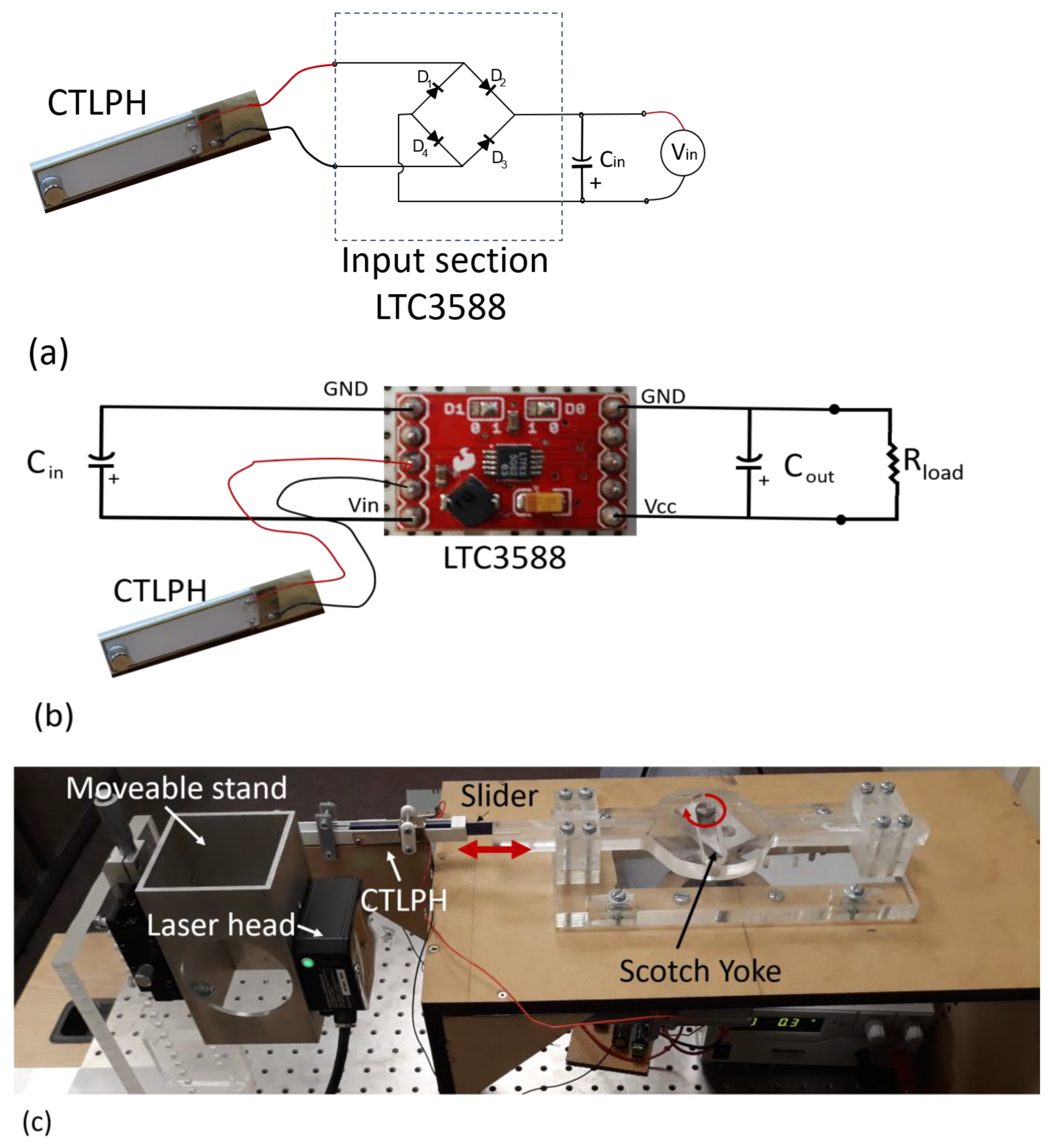
Based on the thermodynamic equilibrium equations, the internal energy of any differential volume element of the triple-layer harvester positioned at x, can be calculated by the internal energy of the upper piezoelectric, substrate, and lower piezoelectric layers given by Equation (17) [21].
d U b e a m = d U u p + d U s + d U l p   .
The individual internal energy of the upper piezoelectric layer can be calculated by
d U u p = 1 2 e u p σ u p + 1 2 D 3 p E 3   .
Replacing e u p and D 3 p by Equation (1), yields to
d U u p = 1 2 σ u p 2 E p d 31 σ u p E 3 + 1 2 ε 33 σ E 3 2   .
Substituting (1a) and Equation (4) in Equation (19) yields to
d U u p = 1 2 ( y 2 R o 2 E p d 31 2 E p E 3 2 + ε 33 σ E 3 2 )   .
The same process for lower piezoelectric and substrate yields to
d U l p = 1 2 e l p σ l p + 1 2 D 3 p E 3 = 1 2 ( y 2 R o 2 E p d 31 2 E p E 3 2 + ε 33 σ E 3 2 )  
and
d U s = 1 2 e s σ s = 1 2 E s e s 2 = y 2 2 R o 2 E s   .
The total internal energy of the beam can be calculated by spatial integrating Equation (17) over the whole volume of the beam:
U b e a m = 0 L 0   w b [ ( t s 2 + t p ) t s 2 d U l p + t s 2 t s 2 d U s + t s 2 t s 2 + t p d U l p ] d x d y d z   .
Replacing Equations (20)–(22) in Equation (23) leads to
U b e a m = 0 L 0 w b [ ( t s 2 + t p ) t s 2 1 2 ( y 2 R o 2 E p d 31 2 E p E 3 2 + ε 33 σ E 3 2 ) + t s 2 t s 2 ( y 2 2 R o 2 E s )           + t s 2 t s 2 + t p 1 2 ( y 2 R o 2 E p d 31 2 E p E 3 2 + ε 33 σ E 3 2 ) ] d x d y d z .
As stated in Equation (14), the curvature radius is a function of the moment. The applied periodic tip force causes a moment at each section in x, presented by Equation (25). The diameter of the tip mass magnet is neglected in Equation (25).
M ( x ) = F ( L x )   .
Substituting Equation (25) in Equation (14) yields to
1 R o   ( x ) = 12 ( F L F x + Δ )   w b λ   .
By considering the electromechanical coupling coefficient, k 31 ( = d 31 2 E p / ε 33 σ ) , the total internal energy of the beam, Equation (24), can be simplified by
U b e a m = 0 L [ λ   w b 24 ( R o   ( x ) ) 2 w b ε 33 σ t p E 3 2 ( 1 k 31 2 ) ] d x   .
For parallel electrical connection of electrodes we have ( E 3 = V / t p ) , where V is externally applied voltage, V, substituting Equations (13) and (26) in Equation (27) and integrating over the length of the beam, yields to
U b e a m = 2 F 2 L 3   w b λ + 6 L 2 λ d 31 E p (   t s + t p ) F V + [ ε 33 σ t p   w b L ( 1 k 31 2 ) + 6 L λ d 31 2 E p 2   w b (   t s + t p ) 2 ] V 2 .
The generated charge value on the electrodes because of externally applied voltage, V, and tip force, F, can be calculated by differentiating internal energy to V:
Q = U b e a m V = 6 L 2 λ d 31 E p (   t s + t p ) F + 2 [ ε 33 σ t p   w b L ( 1 k 31 2 ) + 6 L λ d 31 2 E p 2   w b (   t s + t p ) 2 ] V .
For a harvester under external tip force with no external applied voltage (V = 0), the generated charge can be calculated by Equation (30):
Q = U b e a m V = 6 L 2 λ d 31 E p (   t s + t p ) F   .
The tip deflection, δ , of the beam under externally applied voltage, V, and tip force F can be calculated as
δ = U b e a m F = 4 F L 3   w b λ + 6 L 2 λ d 31 E p (   t s + t p ) V   .
Thus, for the harvester under external tip force with no external applied voltage (V = 0), tip deflection can be calculated by Equation (32):
δ = 4 F L 3   w b λ   .
By replacing Equations (12) and (16) in Equation (32), the well-known relationship between tip deflection and tip force can be confirmed in Equation (33) [26]:
δ = F L 3 3 E I   .
In the energy regulator module (Figure 3a), the generated voltage by the CTLPH is rectified by a germanium bridge diode. The rectified voltage is stored in a parallel capacitor called a storage capacitor, Cin. With the use of Equation (30) and considering ( L   w b ) as the surface of the electrode, the voltage across the storage capacitor can be calculated as [27]
V i n = Q C p i e z o + C i n   .
By substituting Equation (30) in Equation (34) and assuming C p i e z o C i n , Equation (34) can be presented as Equation (35):
V i n = 6 L 2 d 31 E p (   t s + t p ) F λ C i n   .
It is obvious that any piezoelectric material with a larger d 31 can generate a higher voltage. As shown in Figure 3b, the external load, a purely electrical resistance, is parallel to the output capacitor (Cout) of the voltage regulator module, LTC3588. In Figure 4, the discharging voltage level of the Cout, Δ V o u t , is the voltage difference between the fully charged condition (i.e., point A) and the partially discharged condition (i.e., point B). Based on the energy conservation principle, the stored energy in Cout is equal to the dissipated energy on the external load, E o u t , which can be calculated by Equation (36):
E o u t = 1   2 C o u t ( Δ V o u t ) 2   .
Depending on the resistor values in the RC circuit of Figure 3b, the discharge period,   T d i s , varies. Therefore, the power dissipated on the resistor can be calculated by Equation (37):
P = E o u t T d i s = C o u t ( Δ V o u t ) 2 2   T d i s

4. Methodology

To examine Equation (35), the effect of Cin on Vin, the input section of LTC3588 should be simulated by using a diode bridge. Then, a germanium diode bridge (1N34A) was employed to rectify the CLTPH output and store it in various Cin, (Figure 3a). LTC 3588 was also used to regulate the output voltage of the CLTPH (Figure 3b). To investigate the performance of the harvester, a reciprocated mechanism, depicted in Figure 3c, was employed. In this mechanism, a slider with a tip magnet is coupled with a Scotch yoke to generate a reciprocated motion with adjustable frequency. The variable low frequency (1–3.2 Hz) of the reciprocating motion is achievable by changing the energizing voltage of the DC motor. The specifications of the employed CTLPH are presented in Table 1. As shown in Figure 3c, a very sensitive laser displacement sensor, model HK-052, measures the vibration amplitude at the tip of the beam and the tip displacement (δ) without mechanical contact [28]. To collect the data, the National Instrument data acquisition card BNC-2110 was employed. To compare the results, the triple-layer harvester is composed of a brass strip (ts = 0.11 mm, Es= 110 GPa) that is sandwiched between two PZT-5H layers (ts = 0.225 mm, Ep = 60 GPa). The material constants of PZH-5H are given by d31 = −270 × 10−12 C/N, k31 = 0.38, and ε 33 σ / ε 0 = 3500 [29].

5. Results and Discussion

5.1. Tip Force

The analytical relationship of Equation (35) predicts the effect of applied force, F, material properties (i.e., elastic modulus, electromechanical coupling coefficient), geometrical dimensions (i.e., the thickness of layers and length of the beam), and the storage capacitance (Cin) on generated voltage by the harvester. The values of all of the parameters can be found in the catalog of the piezoelectric material manufacturer or can be measured. Figure 5 shows the tip deflection of the CTLPH when the slider reciprocates at various low frequencies. The maximum deflection for all frequencies is about 2.7 mm. In the next step, considering the values in Table 1, bending stiffness, EI, can be computed as 0.0088 N·m2 using Equation (16). By replacing the bending stiffness value (EI = 0.0088 N·m2) and maximum tip deflection δ m a x = 2.7   mm , in (33), the maximum applied tip force can be specified, F = 3 E I × δ / L 3 = 3 × 0.0088 × 0.0027 / 0.035 3 = 1.66   N .

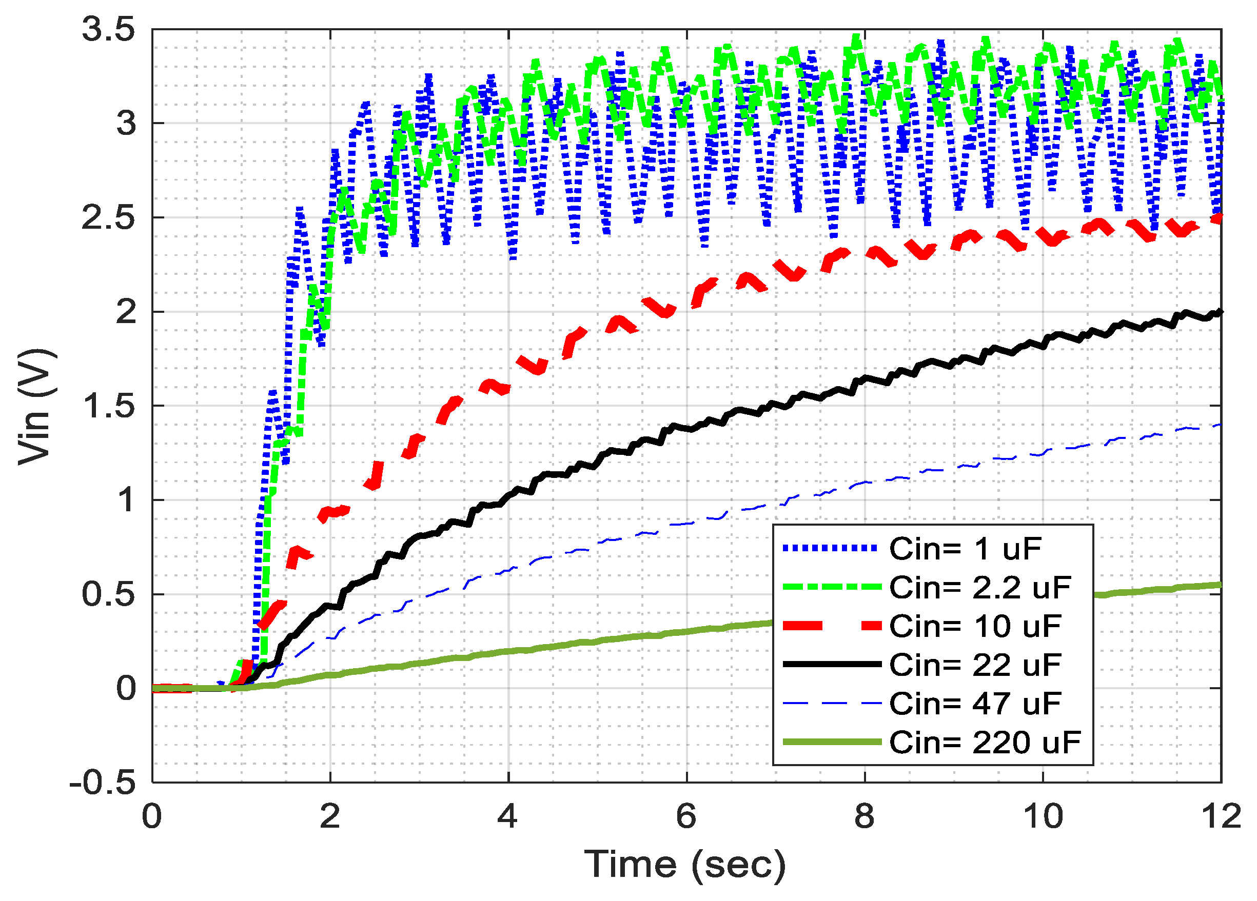
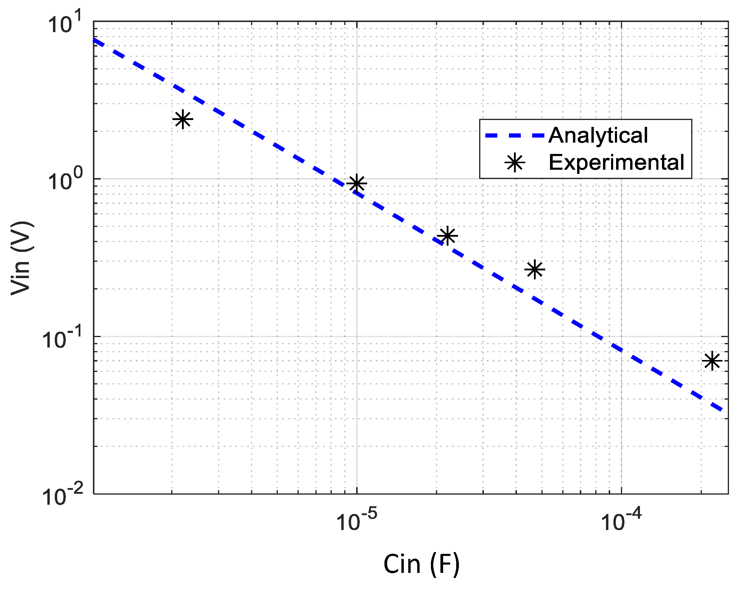
5.2. Storage or Input Voltage

In this section, the performance of the employed CTLPH (specifications in Table 1) was investigated when it was connected to the germanium diode bridge. As depicted in Figure 4a by changing the storage capacitors (Cin), the voltage across the storage capacitors (Vin) was measured. Figure 6 shows Vin versus time for a variety of Cin values; the higher Cin, the lower the storage voltage. Figure 7 shows Vin versus Cin at a given time of 2 s. This figure confirms that the stored voltage (Vin) has a reverse relationship with Cin, as Equation (35) suggests.

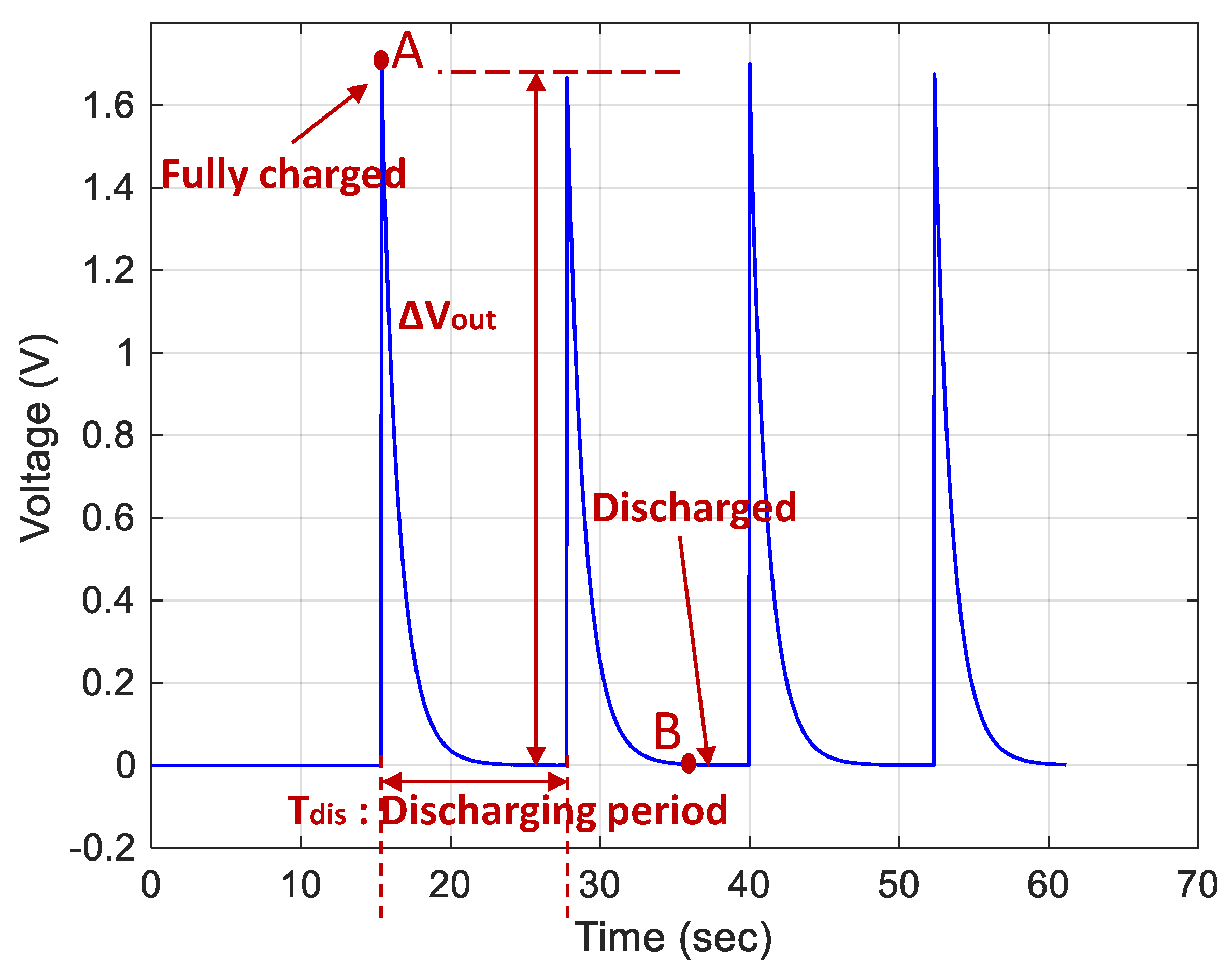
5.3. Output Voltage and Power with LTC3588

In this section, an energy storage module, LTC3588, is employed to regulate the output harvested voltage and power. Since the employed storage module is commercialised and its simulator is not available, it was required to characterise it. Then, the output terminals of the CTLPH were connected to the input terminals of the LTC3588 and the effect of the variable parameters, such as motion frequencies (up to 3.2 Hz), storage capacitors (Cin), output capacitors (Cout), and resistive loads were investigated. The rectified voltage (after the germanium diode bridge) is stored in the storage capacitor (Cin). In each reciprocated motion, generated by the Scotch Yoke, the bending deflection of the CTLPH increases the accumulated charges on the Cin, which is proportional to Vin.

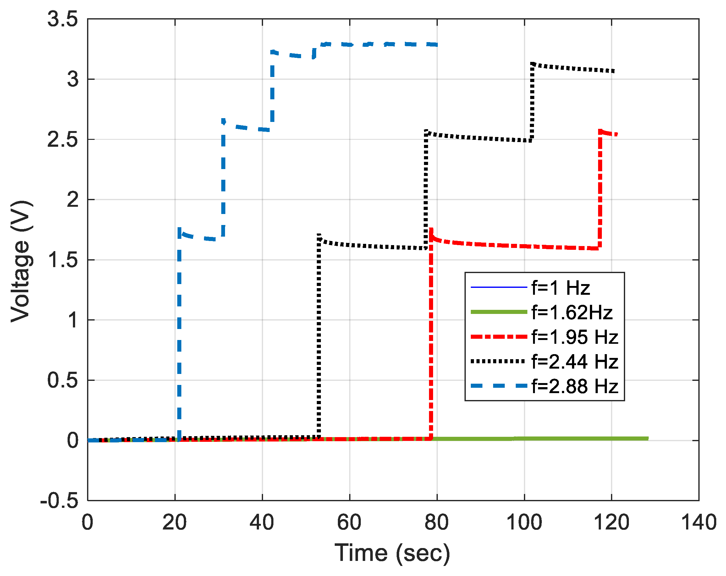
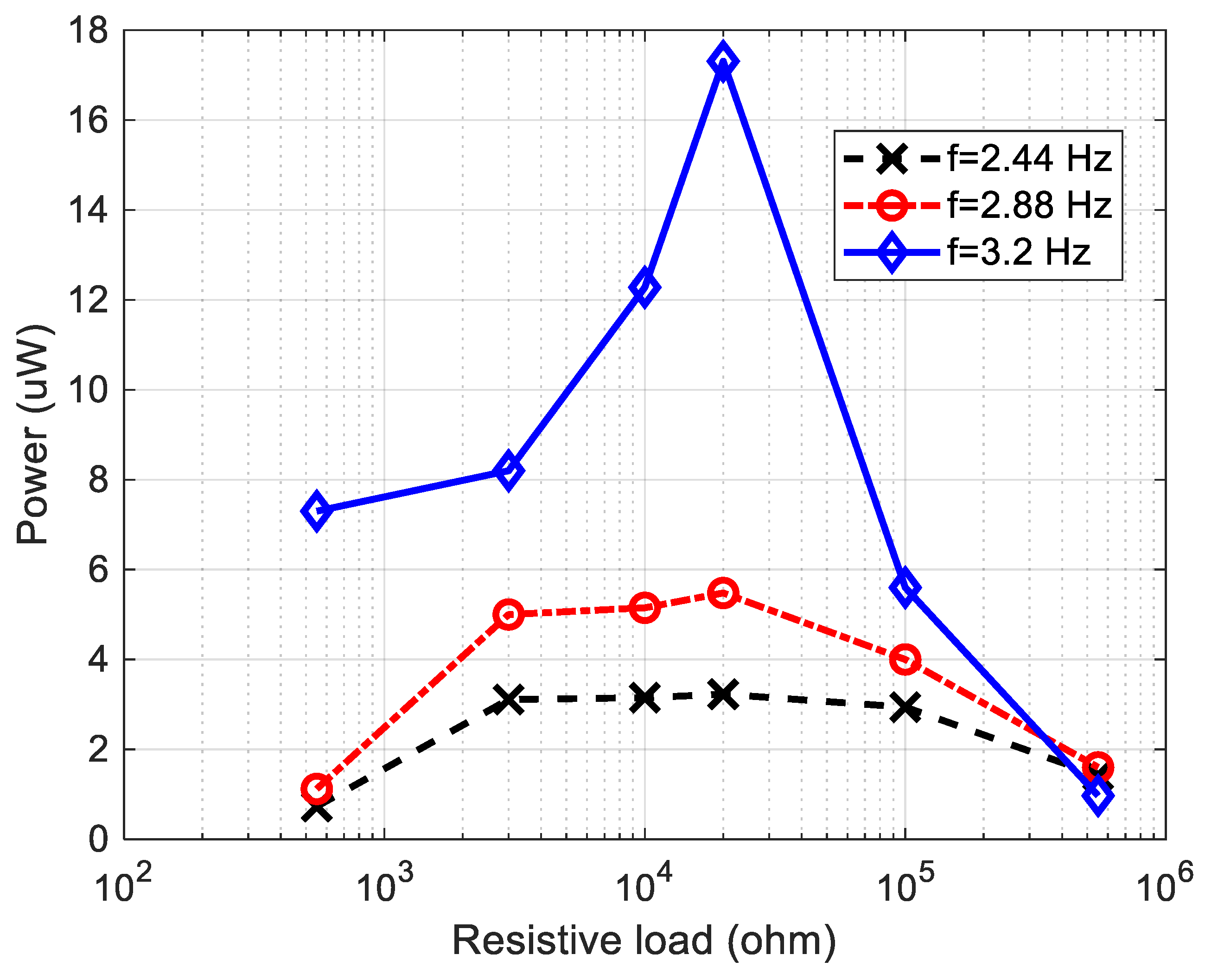
5.3.1. Effect of Frequency

Figure 8 shows that the output voltage increases steeply across the Cout terminals when the CTLPH is bent by variable frequency. Since the output voltage of LTC3588 is set at 3.3 V, the output voltage cannot exceed this value. This figure highlights that higher frequency causes faster charging and reaches the set value of 3.3 V. The generated charge in low frequency (e.g., f = 1.62 and 1 Hz) does not generate a voltage in the monitoring period of 120 s.

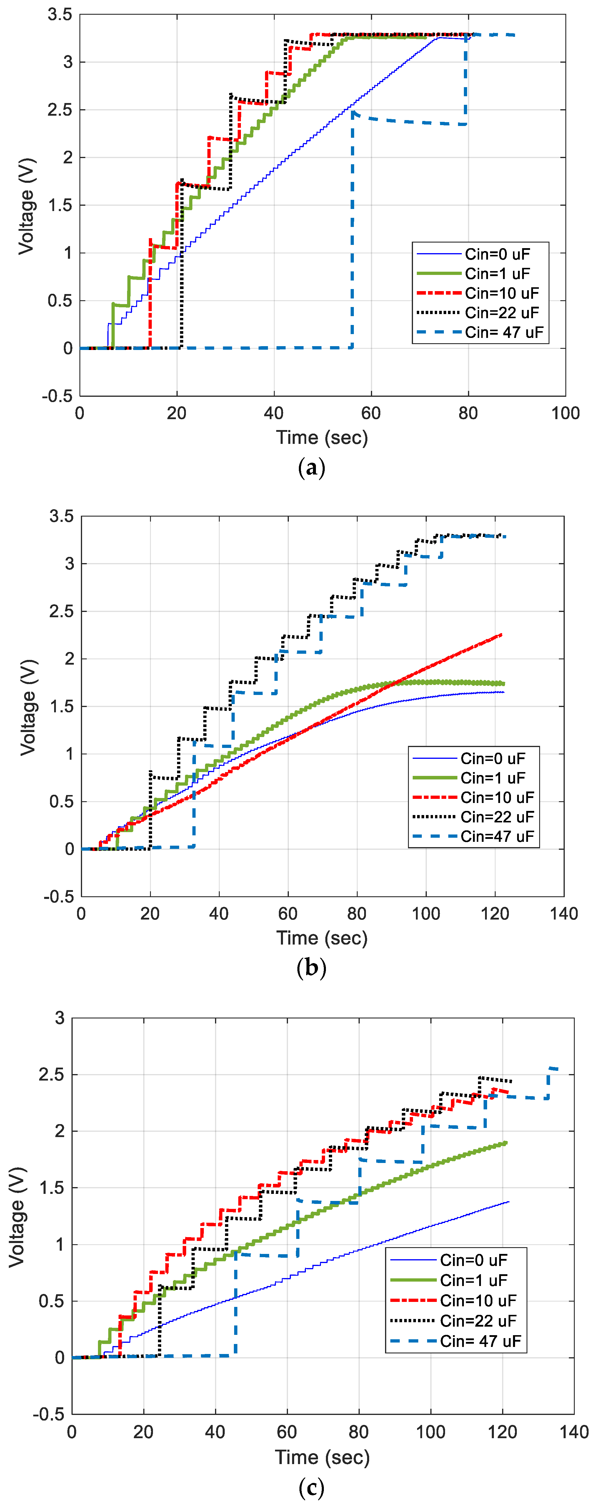
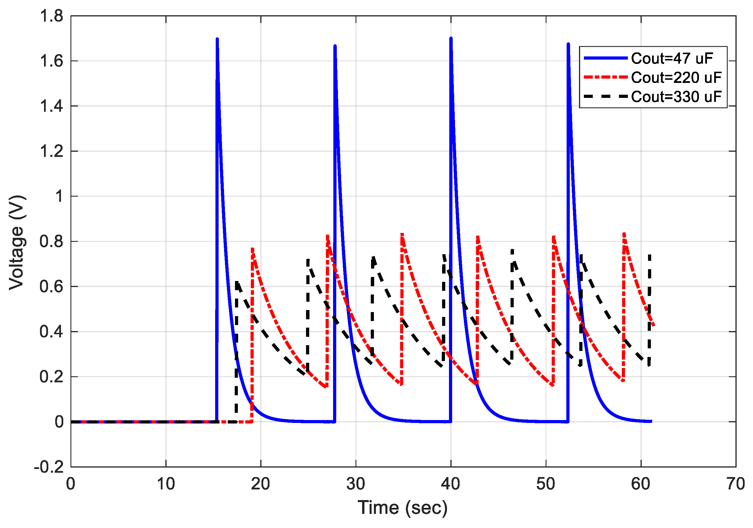
5.3.2. Effect of Storage and Output Capacitors

The effect of the storage capacitor, Cin, and output capacitor, Cout, on the output voltage (Vout) is manifested in Figure 9 when the slider moves at 2.88 Hz in an open circuit condition. For the same charge generated by the CTLPH, a lower Cin, causes a larger Vin. By increasing the Cin, more charges need to be stored to reach the threshold voltage value. In other words, a higher charging period causes later charge transportation to the output capacitor. Comparison of Figure 9a–c for any Cin (e.g., for Cin = 22 μ F) show lower Cout, which leads to higher Vout.

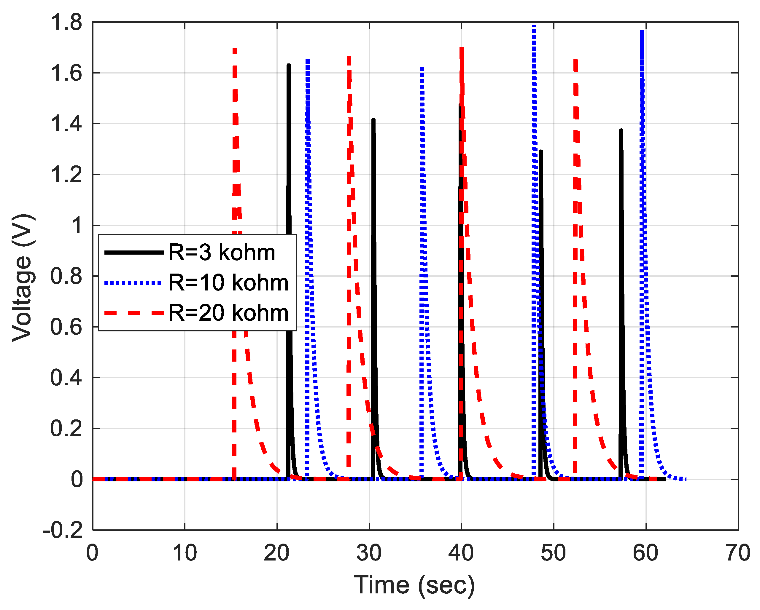
5.3.3. Effect of Resistive Load

To investigate the effect of load (i.e., resistive type) on the output power of the CTLPH, we measured the generated energy and power for one discharging period, Tdis. Figure 10 emphasises again the role of Cout to provide output voltage with a lower ripple or smaller Δ V o u t .
Figure 11 also highlights the electrical resistive load effect on the discharging period, Tdis, where larger resistance increases Tdis. Changing load value affects both the Δ V o u t and Tdis. By substituting the measured values of Δ V o u t and Tdis in Equation (37), the generated power of each resistive load,   R l o a d , can be calculated (Figure 12). When the load is small, the voltage drop across the load is low (e.g., in a short circuit condition the output voltage is zero). By increasing the external resistive load, the output voltage (voltage drop across the external load) varies. Furthermore, higher excitation frequency causes a faster storage or voltage raise. Figure 12 shows that the power will reach its maximum value in a specific resistance and mitigates in the higher values. As an example, Δ V o u t was measured at 1.9 V for R = 20 kΩ at the frequency of 3.2 Hz. By substituting the measured value of Δ V o u t in (36), the discharge energy from the output capacitor (Cout = 47 µF) is 84.83 μ J . Considering Tdis = 4.9 s, it causes a power of 17.31 µW. Similarly, the maximum power for 2.44 and 2.88 Hz at 20 kΩ would be 2.23 and 5.48 µW, respectively. In other words, the maximum output power of the CTLPH combined with LTC3588 module is realised when it is connected to a 20 kΩ external load. In other words, the proposed CTLPH in this research with 17.31 µW output power is a good candidate to empower microelectronic sensors or biomedical implants (e.g., 30 µW pacemakers). Compared with other harvesters presented in Table 2, the highest power density of this work (i.e., 77.2 µW/cm3) can be related to many factors, such as piezoelectric coefficient (d31) or amplitude of applied tip force (as shown in Equation (35)). Although higher applied force can generate higher voltage, it leads to more microstructural cracks and lower longevity of the harvester. Therefore, a trade-off between lifespan and power density should be considered for real-life applications.

6. Conclusions

A design guideline for kinetic energy conversion of a cantilever triple-layer piezoelectric harvester (CTLPH) for a low-frequency excitation is presented. The effective parameters of CTLPH were determined by combining constitutive equations with internal energy equations, resulting in the prediction of output voltage and power generated by the harvester. The model revealed that the frequency of motion, applied tip force, piezoelectric coefficients, geometrical dimensions, and mechanical properties of the layers are all critical to the performance of the CTLPH. Furthermore, the dependency of output voltage on the storage (Cin) and output capacitor of the energy storage module, LTC3588, is investigated. An impractical measurement method without mechanical contact is employed to specify the applied tip force. The performance of the CTLPH in low frequencies (<3.3 Hz) for various resistive loads is also investigated. It was demonstrated that both the excitation frequency and external resistance load have an impact on the maximum generated power. The developed CTLPH generates the optimum power of 17.31 µW at the external resistance of 20 kΩ, which is suitable for micropower implanted devices operating in environments with a minimum vibration frequency of 3.2 Hz.

Author Contributions

Conceptualization, M.G.; methodology, M.G. and M.M.; software, M.G., M.M. and P.S.; validation, M.G. and M.M.; formal analysis, M.G., M.M. and P.S.; investigation, M.G.; resources, M.G.; data curation, M.G.; writing—original draft preparation, M.G.; writing—review and editing, M.G.; M.M. and P.S.; visualization, M.G. and M.M.; supervision, M.G.; project administration, M.G.; funding acquisition, M.G. All authors have read and agreed to the published version of the manuscript.

Funding

This research was funded by the University of Portsmouth, School of Energy and Electronic Engineering—Internal Funding.

Data Availability Statement

All data are available upon request from the corresponding author.

Acknowledgments

The work was performed with the equipment of the University of Portsmouth. The authors also thank Geoff Britton and William Keeble for their help in the Machining Workshop.

Conflicts of Interest

The authors declare no conflict of interest.

References

  1. Hoshyarmanesh, H.; Ghodsi, M.; Kim, M.; Cho, H.H.; Park, H.-H. Temperature effects on electromechanical response of deposited piezoelectric sensors used in structural health monitoring of aerospace structures. Sensors 2019, 19, 2805. [Google Scholar] [CrossRef] [PubMed] [Green Version]
  2. Du, S.; Jia, Y.; Zhao, C.; Amaratunga, G.A.; Seshia, A.A. A nail-size piezoelectric energy harvesting system integrating a mems transducer and a CMOS SSHI circuit. IEEE Sens. J. 2019, 20, 277–285. [Google Scholar] [CrossRef] [Green Version]
  3. Zhang, M.; Cai, W.; Wang, Z.; Fang, S.; Zhang, R.; Lu, H.; Aliev, A.E.; Zakhidov, A.A.; Huynh, C.; Gao, E. Mechanical energy harvesters with tensile efficiency of 17.4% and torsional efficiency of 22.4% based on homochirally plied carbon nanotube yarns. Nat. Energy 2023, 8, 203–213. [Google Scholar] [CrossRef]
  4. Adhikari, P.R.; Tasneem, N.T.; Reid, R.C.; Mahbub, I. Electrode and electrolyte configurations for low frequency motion energy harvesting based on reverse electrowetting. Sci. Rep. 2021, 11, 5030. [Google Scholar] [CrossRef]
  5. Li, M.; Luo, A.; Luo, W.; Wang, F. Recent progress on mechanical optimization of mems electret-based electrostatic vibration energy harvesters. J. Microelectromech. Syst. 2022, 31, 726–740. [Google Scholar] [CrossRef]
  6. Miao, G.; Fang, S.; Wang, S.; Zhou, S. A low-frequency rotational electromagnetic energy harvester using a magnetic plucking mechanism. Appl. Energy 2022, 305, 117838. [Google Scholar] [CrossRef]
  7. Tasneem, N.T.; Biswas, D.K.; Adhikari, P.R.; Gunti, A.; Patwary, A.B.; Reid, R.C.; Mahbub, I. A self-powered wireless motion sensor based on a high-surface area reverse electrowetting-on-dielectric energy harvester. Sci. Rep. 2022, 12, 3782. [Google Scholar] [CrossRef]
  8. Mohammadzaheri, M.; Soltani, P.; Ghodsi, M. Micro/nanopositioning systems with piezoelectric actuators and their role in sustainability and ecosystems. In Ecomechatronics: Challenges for Evolution, Development and Sustainability; Springer: Berlin/Heidelberg, Germany, 2022; pp. 233–250. [Google Scholar]
  9. Lim, C.; He, L. Three-dimensional exact solutions for the electromechanical response of triple-layer piezoelectric actuators. Smart Mater. Struct. 2004, 13, 1050. [Google Scholar] [CrossRef]
  10. Soltani, P.; Kerschen, G.; Tondreau, G.; Deraemaeker, A. Piezoelectric vibration damping using resonant shunt circuits: An exact solution. Smart Mater. Struct. 2014, 23, 125014. [Google Scholar] [CrossRef] [Green Version]
  11. Soltani, P.; Kerschen, G. The nonlinear piezoelectric tuned vibration absorber. Smart Mater. Struct. 2015, 24, 075015. [Google Scholar] [CrossRef] [Green Version]
  12. Makowski, M.; Knap, L. Study of a controlled piezoelectric damper. Sensors 2021, 21, 3509. [Google Scholar] [CrossRef]
  13. Marakakis, K.; Tairidis, G.K.; Koutsianitis, P.; Stavroulakis, G.E. Shunt piezoelectric systems for noise and vibration control: A review. Front. Built Environ. 2019, 5, 64. [Google Scholar] [CrossRef]
  14. Fang, S.; Chen, K.; Lai, Z.; Zhou, S.; Liao, W.-H. Analysis and experiment of auxetic centrifugal softening impact energy harvesting from ultra-low-frequency rotational excitations. Appl. Energy 2023, 331, 120355. [Google Scholar] [CrossRef]
  15. Dong, L.; Closson, A.B.; Oglesby, M.; Escobedo, D.; Han, X.; Nie, Y.; Huang, S.; Feldman, M.D.; Chen, Z.; Zhang, J.X. In Vivo cardiac power generation enabled by an integrated helical piezoelectric pacemaker lead. Nano Energy 2019, 66, 104085. [Google Scholar] [CrossRef]
  16. Shi, G.; Tong, D.; Xia, Y.; Jia, S.; Chang, J.; Li, Q.; Wang, X.; Xia, H.; Ye, Y. A piezoelectric vibration energy harvester for multi-directional and ultra-low frequency waves with magnetic coupling driven by rotating balls. Appl. Energy 2022, 310, 118511. [Google Scholar] [CrossRef]
  17. Qin, W.; Liu, Q.; Wang, Y.; Xie, Z.; Zhou, Z. Increase output of vibration energy harvester by a different piezoelectric mode and branch structure design. J. Phys. D Appl. Phys. 2022, 56, 034001. [Google Scholar] [CrossRef]
  18. Smits, J.G.; Dalke, S.I.; Cooney, T.K. The constituent equations of piezoelectric bimorphs. Sens. Actuators A Phys. 1991, 28, 41–61. [Google Scholar] [CrossRef]
  19. DeVoe, D.L.; Pisano, A.P. Modeling and optimal design of piezoelectric cantilever microactuators. J. Microelectromech. Syst. 1997, 6, 266–270. [Google Scholar] [CrossRef]
  20. Weinberg, M.S. Working equations for piezoelectric actuators and sensors. J. Microelectromech. Syst. 1999, 8, 529–533. [Google Scholar] [CrossRef]
  21. Wang, Q.-M.; Cross, L.E. Constitutive equations of symmetrical triple layer piezoelectric benders. IEEE Trans. Ultrason. Ferroelectr. Freq. Control 1999, 46, 1343–1351. [Google Scholar] [CrossRef]
  22. Tadmor, E.B.; Kósa, G. Electromechanical coupling correction for piezoelectric layered beams. J. Microelectromech. Syst. 2003, 12, 899–906. [Google Scholar] [CrossRef] [Green Version]
  23. Ismail, M.R.; Omar, F.K.; Ajaj, R.; Ghodsi, M. Correction factor of lumped parameter model for linearly tapered piezoelectric cantilever. J. Intell. Mater. Syst. Struct. 2022, 33, 474–488. [Google Scholar] [CrossRef]
  24. Lu, Q.; Liu, L.; Scarpa, F.; Leng, J.; Liu, Y. A novel composite multi-layer piezoelectric energy harvester. Compos. Struct. 2018, 201, 121–130. [Google Scholar] [CrossRef]
  25. Meirovitch, L. Fundamentals of Vibrations; Waveland Press: Long Grove, IL, USA, 2010. [Google Scholar]
  26. Inman, D.J. Engineering Vibration, 4th ed.; Pearson Education Ltd.: London, UK, 2014. [Google Scholar]
  27. ANSI/IEEE Std 176-1987; IEEE Standard on Piezoelectricity. The Institute of Electrical and Electronics Engineers: New York, NY, USA, 1988.
  28. Ghodsi, M.; Ziaiefar, H.; Mohammadzaheri, M.; Omar, F.K.; Bahadur, I. Dynamic analysis and performance optimization of permendur cantilevered energy harvester. Smart Struct. Syst. 2019, 23, 421–428. [Google Scholar]
  29. Available online: https://www.steminc.com (accessed on 6 June 2022).
  30. Wu, Y.; Qiu, J.; Zhou, S.; Ji, H.; Chen, Y.; Li, S. A piezoelectric spring pendulum oscillator used for multi-directional and ultra-low frequency vibration energy harvesting. Appl. Energy 2018, 231, 600–614. [Google Scholar] [CrossRef]
  31. Wei, X.; Zhao, H.; Yu, J.; Zhong, Y.; Liao, Y.; Shi, S.; Wang, P. A tower-shaped three-dimensional piezoelectric energy harvester for low-level and low-frequency vibration. Int. J. Precis. Eng. Manuf.-Green Technol. 2021, 8, 1537–1550. [Google Scholar] [CrossRef]
  32. Zhang, Q.; Liu, Z.; Jiang, X.; Peng, Y.; Zhu, C.; Li, Z. Experimental investigation on performance improvement of cantilever piezoelectric energy harvesters via escapement mechanism from extremely low-frequency excitations. Sustain. Energy Technol. Assess. 2022, 53, 102591. [Google Scholar] [CrossRef]
  33. Li, M.; Zhou, J.; Jing, X. Improving low-frequency piezoelectric energy harvesting performance with novel x-structured harvesters. Nonlinear Dyn. 2018, 94, 1409–1428. [Google Scholar] [CrossRef]
Figure 1. The CTLPH (a) A schematic, (b) bending deflection in a reciprocating motion, and (c) a real mechanism.
Energies 16 03129 g001
Figure 2. (a) A cantilever triple-layer piezoelectric harvester in transverse vibration. (b) Free-body diagram of a small element. (c) Parallel connection. (d) Series connection.
Energies 16 03129 g002
Figure 3. Performance evaluation. (a) Germanium diode bridge (1N34A) of the input section of LTC3588. (b) Connection of energy regulator module, LTC3588. (c) Driving and measurement setup.
Energies 16 03129 g003
Figure 4. Discharging voltage versus time when LTC3588 is connected to the external load Rload = 20 k Ω ; Cin = 22 μ F; Cout = 47 μ F; and f = 2.88 Hz.
Energies 16 03129 g004
Figure 5. Tip deflection measurement of CTLPH at various slider frequencies.
Energies 16 03129 g005
Figure 6. Storage voltage (Vin) vs. time for various storage capacitors (Cin); f = 3.3 Hz.
Energies 16 03129 g006
Figure 7. Effect of the storage capacitor (Cin) on the storage voltage (Vin) after 2 s; f = 3.3 Hz.
Energies 16 03129 g007
Figure 8. Frequency effect on the open circuit output voltage of LTC3588; Cin = 22 μ F, Cout = 47 μ F.
Energies 16 03129 g008
Figure 9. The output voltage of LTC3588 versus time for different values of Cin and for open circuit; f = 2.88 Hz (a) Cout = 47 µF, (b) Cout =220 µF, and (c) Cout = 330 µF.
Energies 16 03129 g009
Figure 10. The output voltage of LTC3588 versus time for different values of Cout, when LTC3588 is connected to the external load Rload = 20 k Ω ; Cin = 22 μ F; and f = 2.88 Hz.
Energies 16 03129 g010
Figure 11. Sample of discharging voltage of LTC3588 when connected to the various external load; Cin = 22 μ F; Cout = 47 μ F; and f = 2.88 Hz.
Energies 16 03129 g011
Figure 12. Generated power versus external resistance load for different motion frequencies; Cin = 22 μ F; and Cout = 47 μ F.
Energies 16 03129 g012
Table 1. Parameters of employed CTLPH sample in the experiment.
Substrate LayerPiezoelectric LayerTip MassTiple-Layer Beam
MaterialBrassPZT-5HNdFeB-N35PZT-Brass-PZT
Dimensions (mm) 40 × 10 × 0.1140 × 10 × 0.225 5 × 5 40 × 10 × 0.56
Elastic modulus (GPa)1106038----
Density (kg/m3)7800 65007500----
Mass (kg)0.000340.000580.00075 0.0015
Table 2. Comparison of the output power of similar piezoelectric harvester.
Ref. Dimensions (mm)MaterialFrequency (Hz)Power (µW)Resistance (MΩ)Power Density (µW/cm3)
[30]160 × 85 × 85Unknow PZT2.03132900.5411.5
[31]40 × 70 × 35PVDF3.465.8150.67
[32]48 × 10 × 65Unknow PZT13531.12
[33]300 × 200 × 250PZT 5J2.51460.50.00973
This work40 ×10 × 0.56PZT-5H3.2 17.310.0277.2
Disclaimer/Publisher’s Note: The statements, opinions and data contained in all publications are solely those of the individual author(s) and contributor(s) and not of MDPI and/or the editor(s). MDPI and/or the editor(s) disclaim responsibility for any injury to people or property resulting from any ideas, methods, instructions or products referred to in the content.

