

In-Wheel Motor Drive Systems for Electric Vehicles: State of the Art, Challenges, and Future Trends
 , ,
, ,  , and
, and
Abstract
:1. Introduction
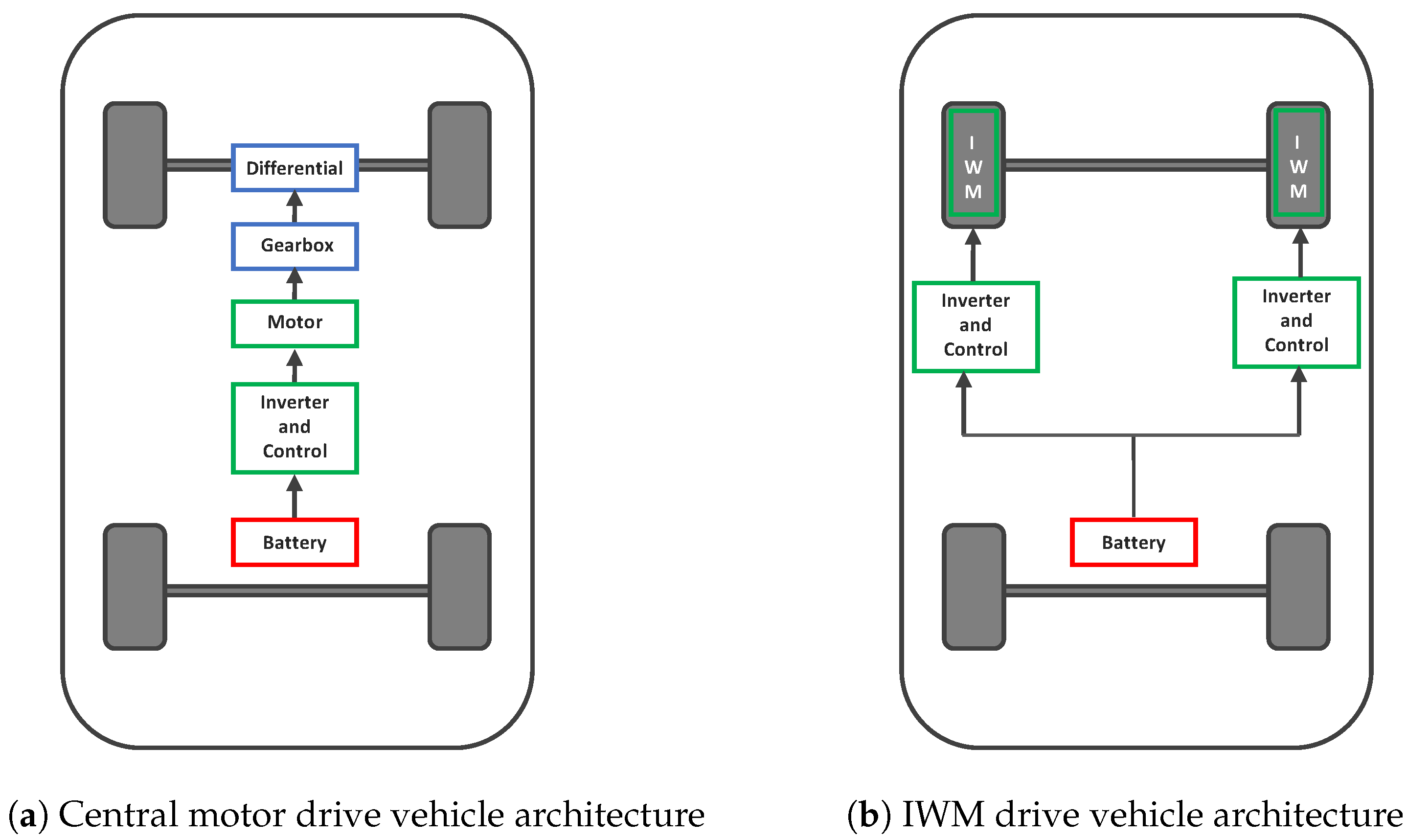
1.1. In-Wheel Motor Drives vs. Central-Motor Drives
- A larger number of components introduced from transmission;
- Over 10% of vehicle weight is contributed due to transmission components;
- 15% losses contributed from transmission and slip efficiency;
- Decreased space for passenger, cargo, and battery.
- Compact structure with short axial length;
- Largest possible diameter of airgap for a given wheel size. Outer rotor topologies are suitable;
- High efficiency at lower speeds as the wheel is driven directly by the motor without reduction gearbox;
- High torque density; achieved through by utilizing high pole pair number;
- Light weight to reduce unsprung mass;
- Robust and fault tolerant to endure the aggressive and harsh operating environment of IWM.
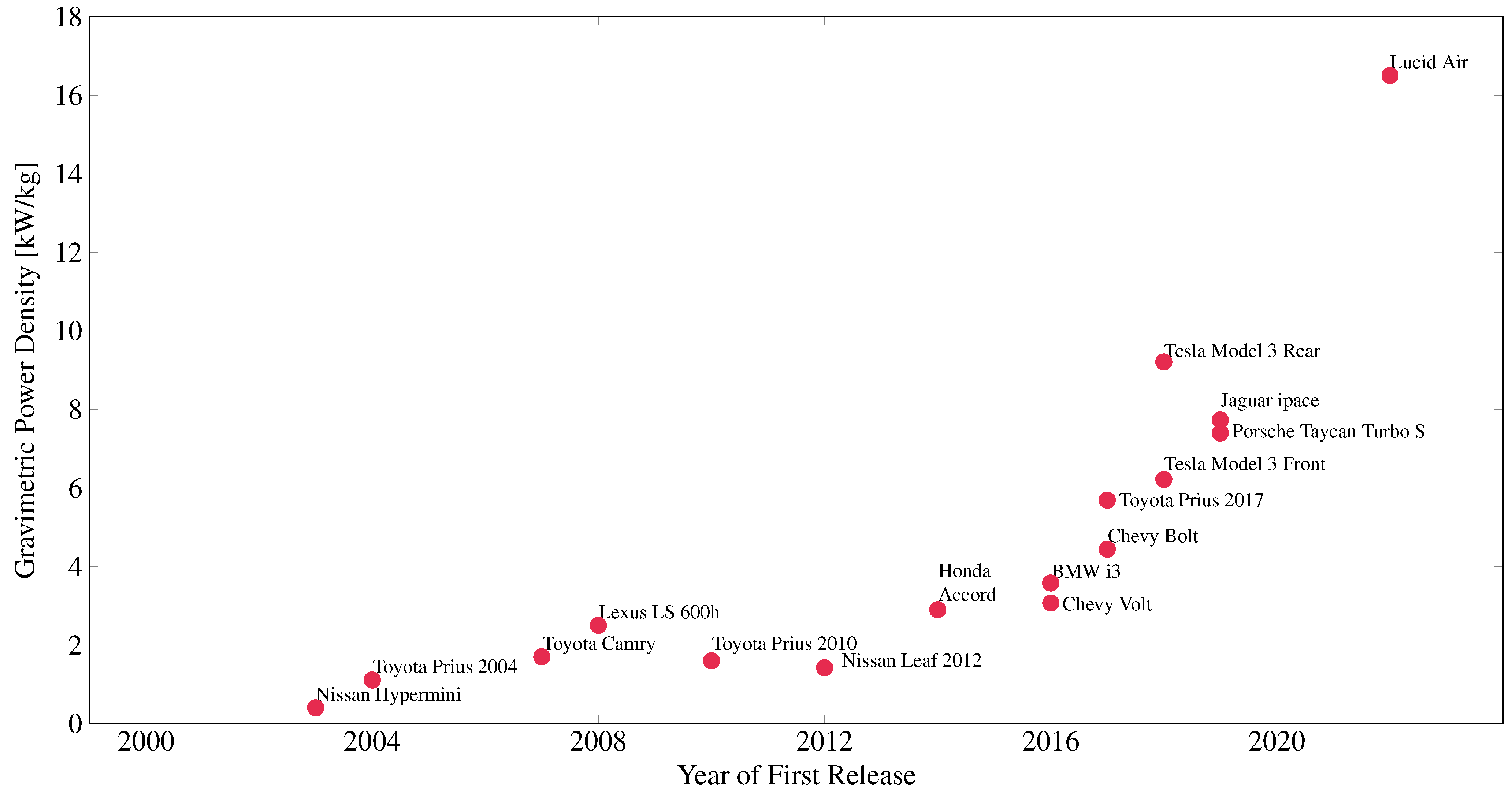
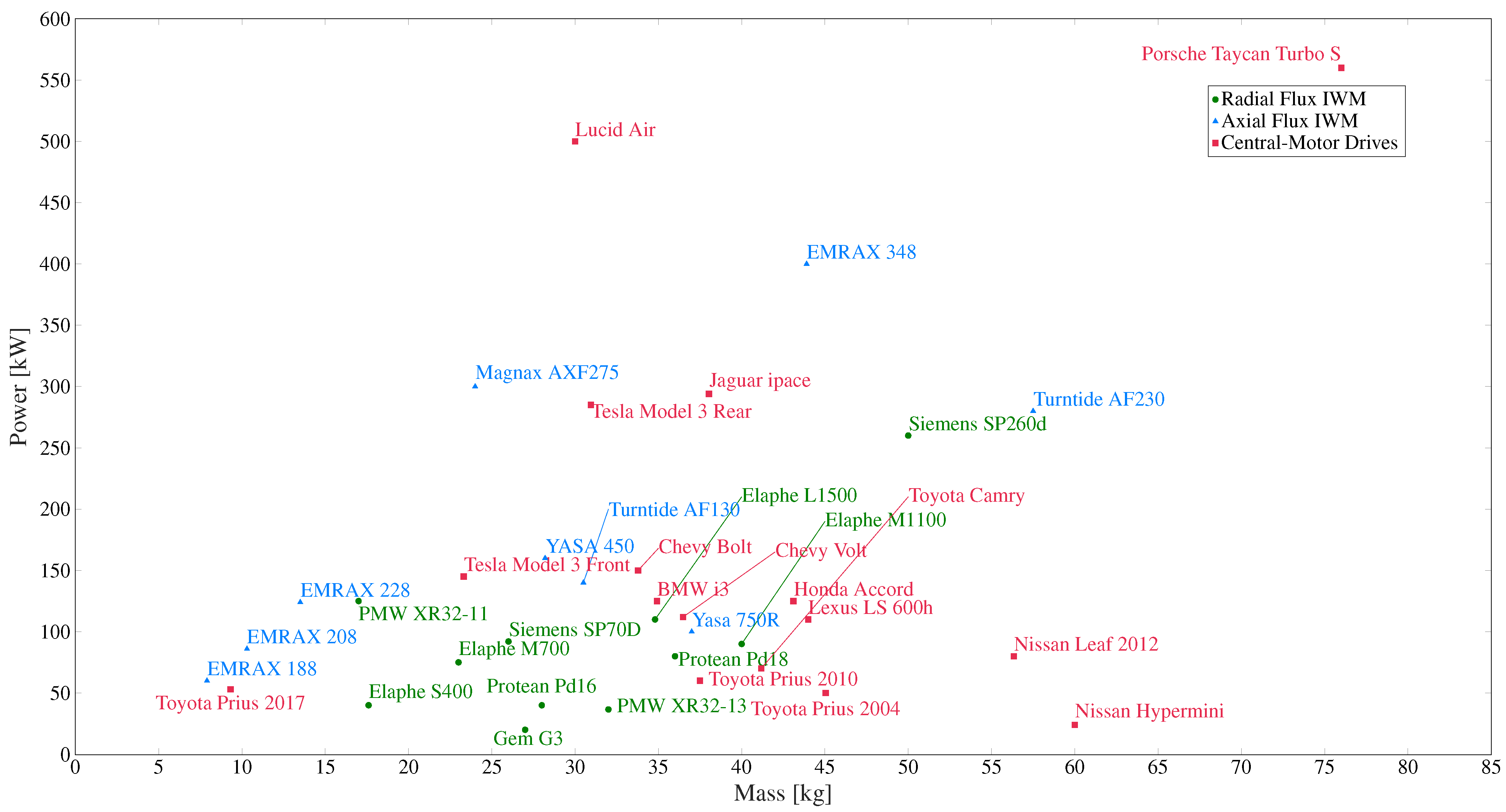
1.2. State of the Art in Central-Motor Drive EVs
2. Motor Topologies for IWMs
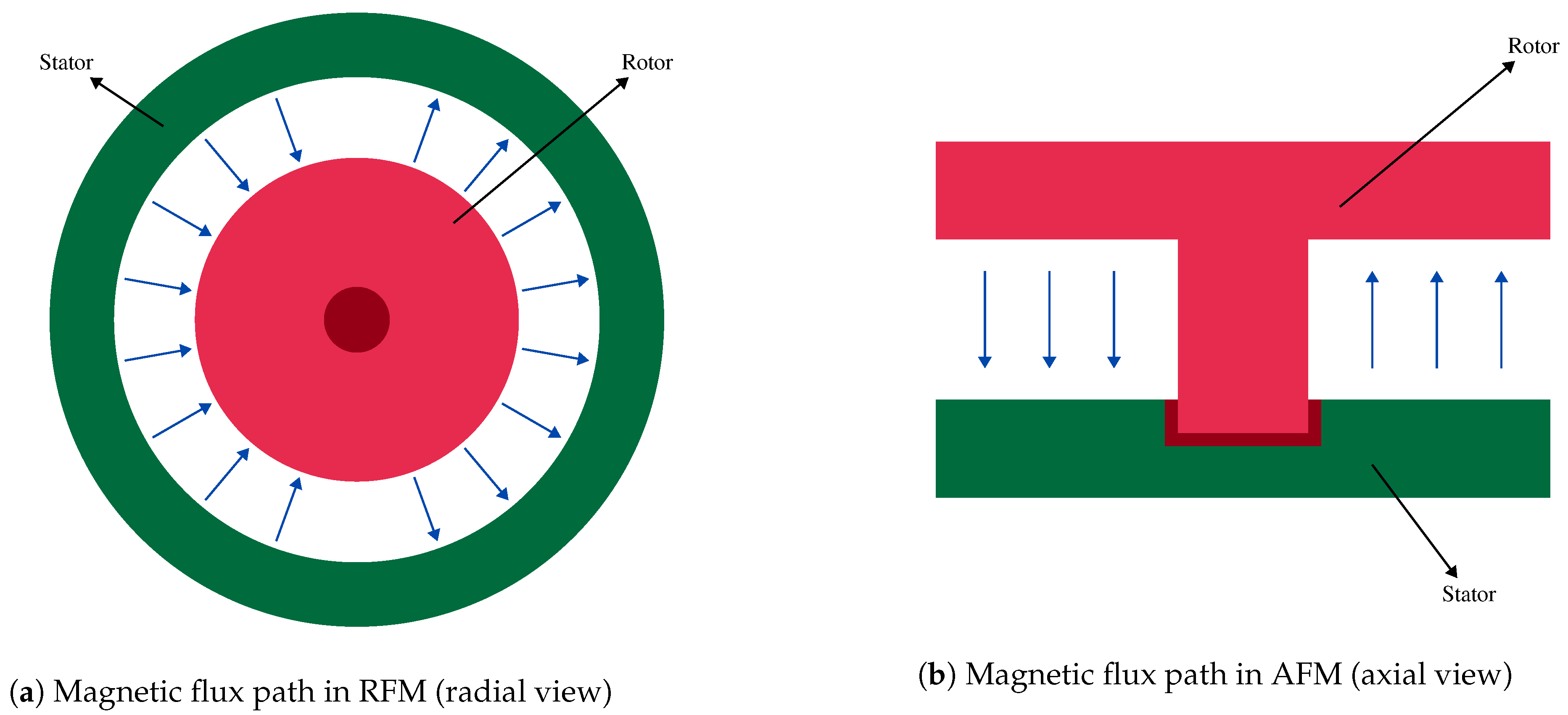
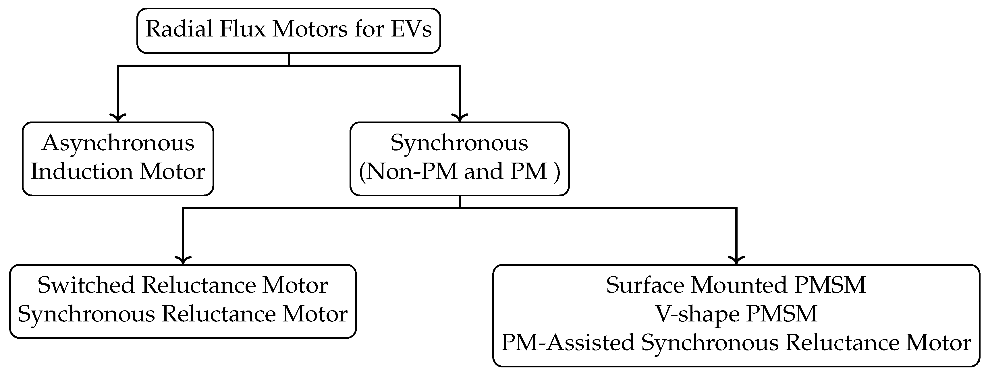
2.1. Radial Flux Motors
2.1.1. Topologies of Radial Flux Motors in IWMs
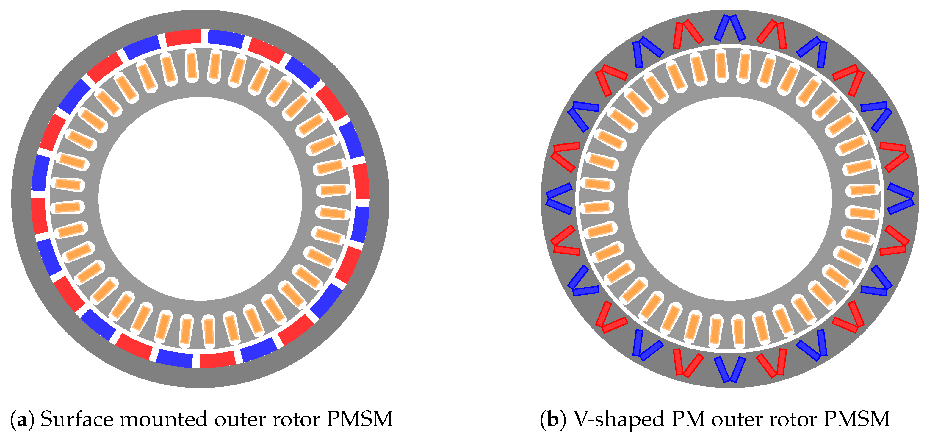
Permanent Magnet Synchronous Motors
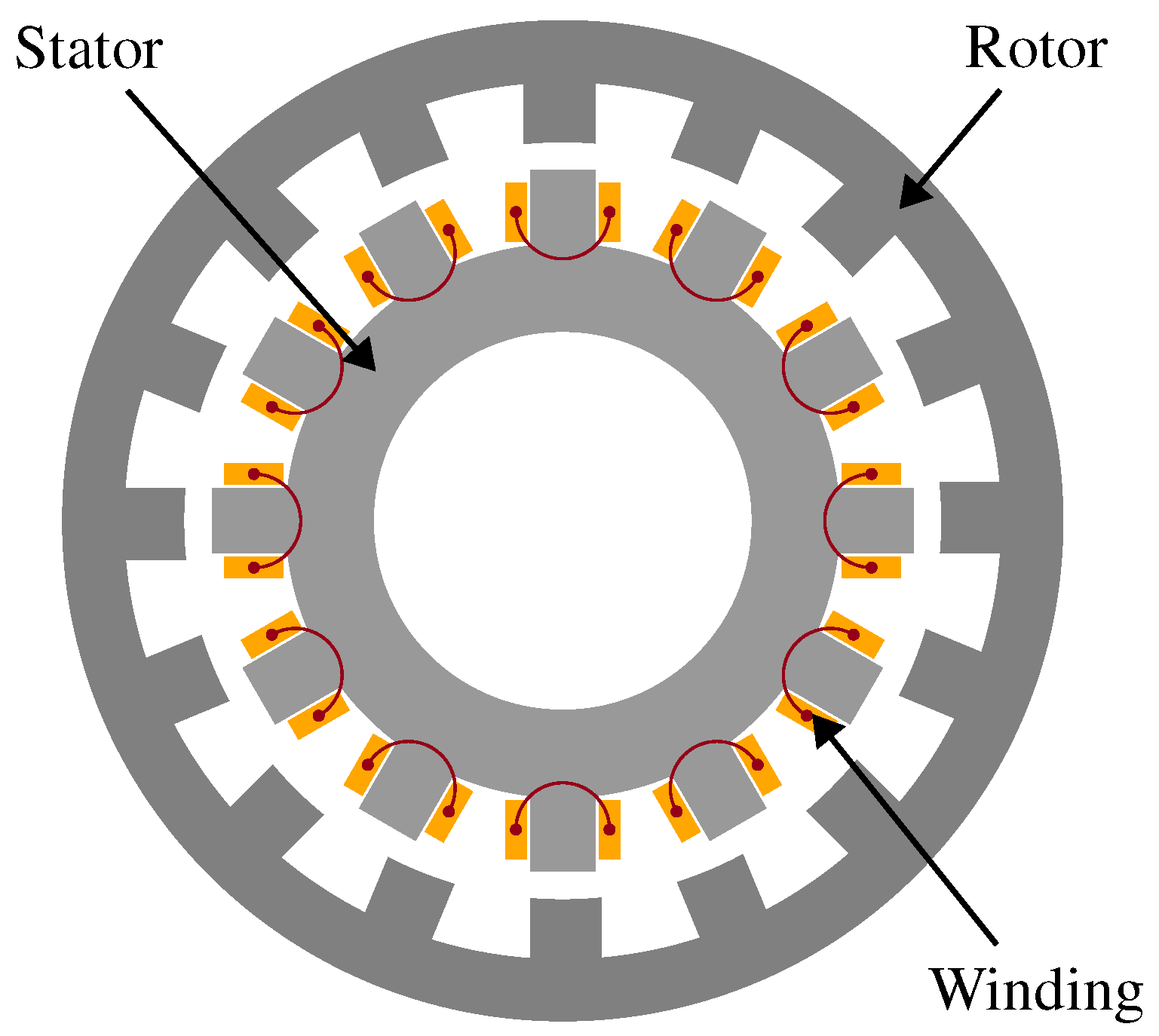
Switched Reluctance Motor
Synchronous Reluctance Motor
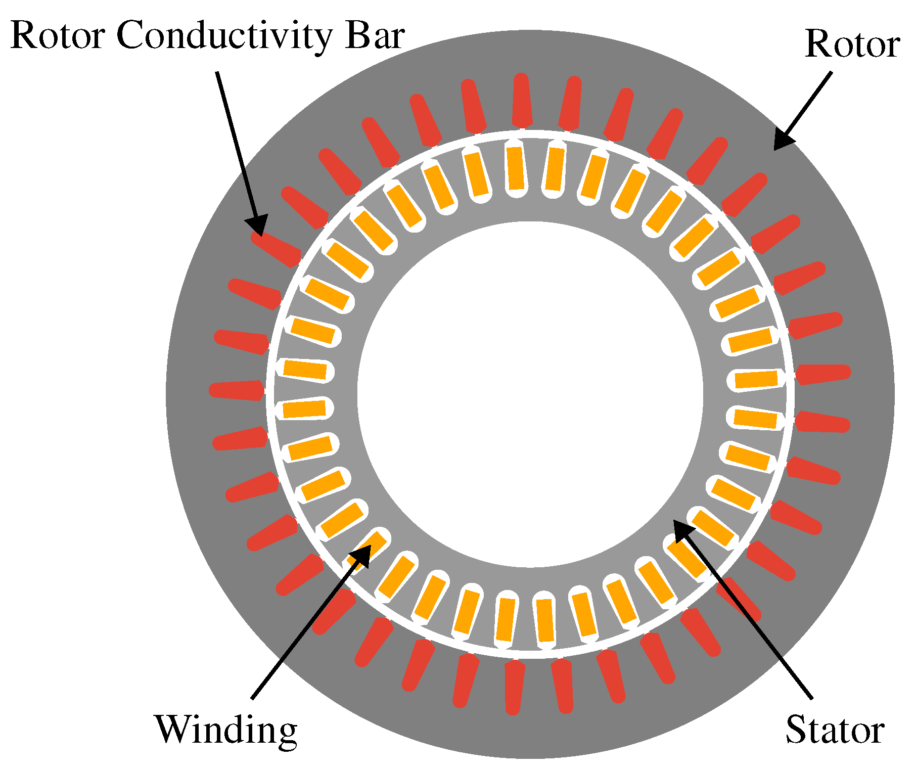
Induction Motor
2.1.2. Industrial State of the Art in Radial Flux Motors for IWMs
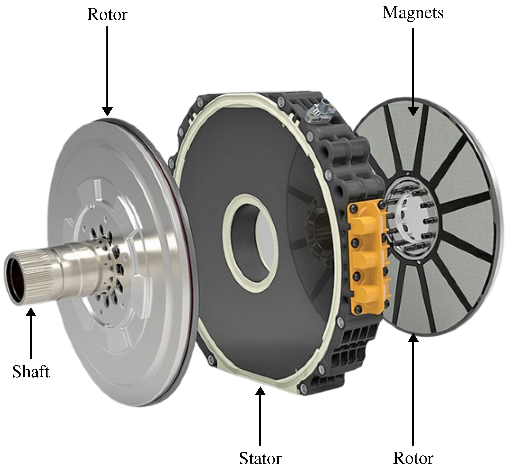
2.2. Axial Flux Motors
- Compact structure, especially short axial sizes which is ideal for IMW technology;
- Small stator core volume, therefore reduced stator core loss;
- Low weight;
- High torque density;
- High power density;
- Flexible and modular structure; motors can be stacked axially to increase the torque and power;
- Small end-winding hence lower copper losses.
- Manufacturing and assembly problems due to complicated structure;
- Higher cost;
- Prone to non-uniform airgap due to strong axial magnetic forces between stator and rotor.
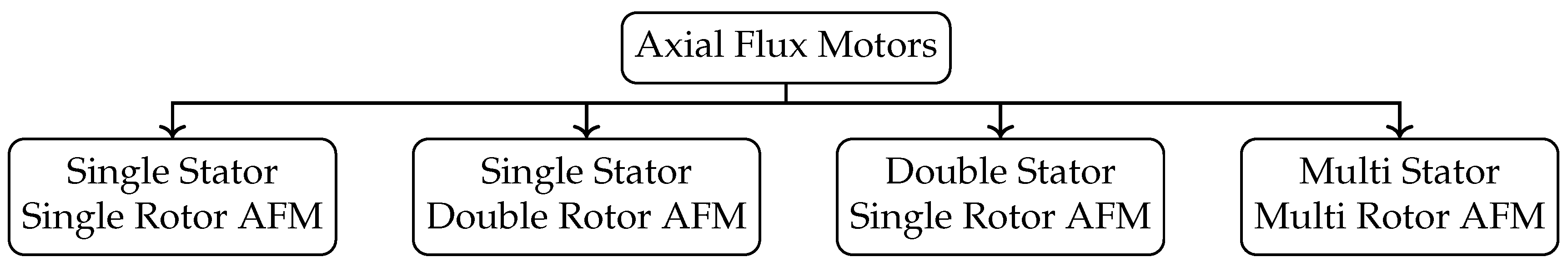
2.2.1. Topologies of Axial Flux Motors
Single-Stator Single-Rotor (SSSR)
Single-Stator Double-Rotor (SSDR)
Double-Stator Single-Rotor (DSSR)
Multi-Stator Multi-Rotor (MSMR)
2.2.2. Industrial State of the Art in Axial Flux Motors
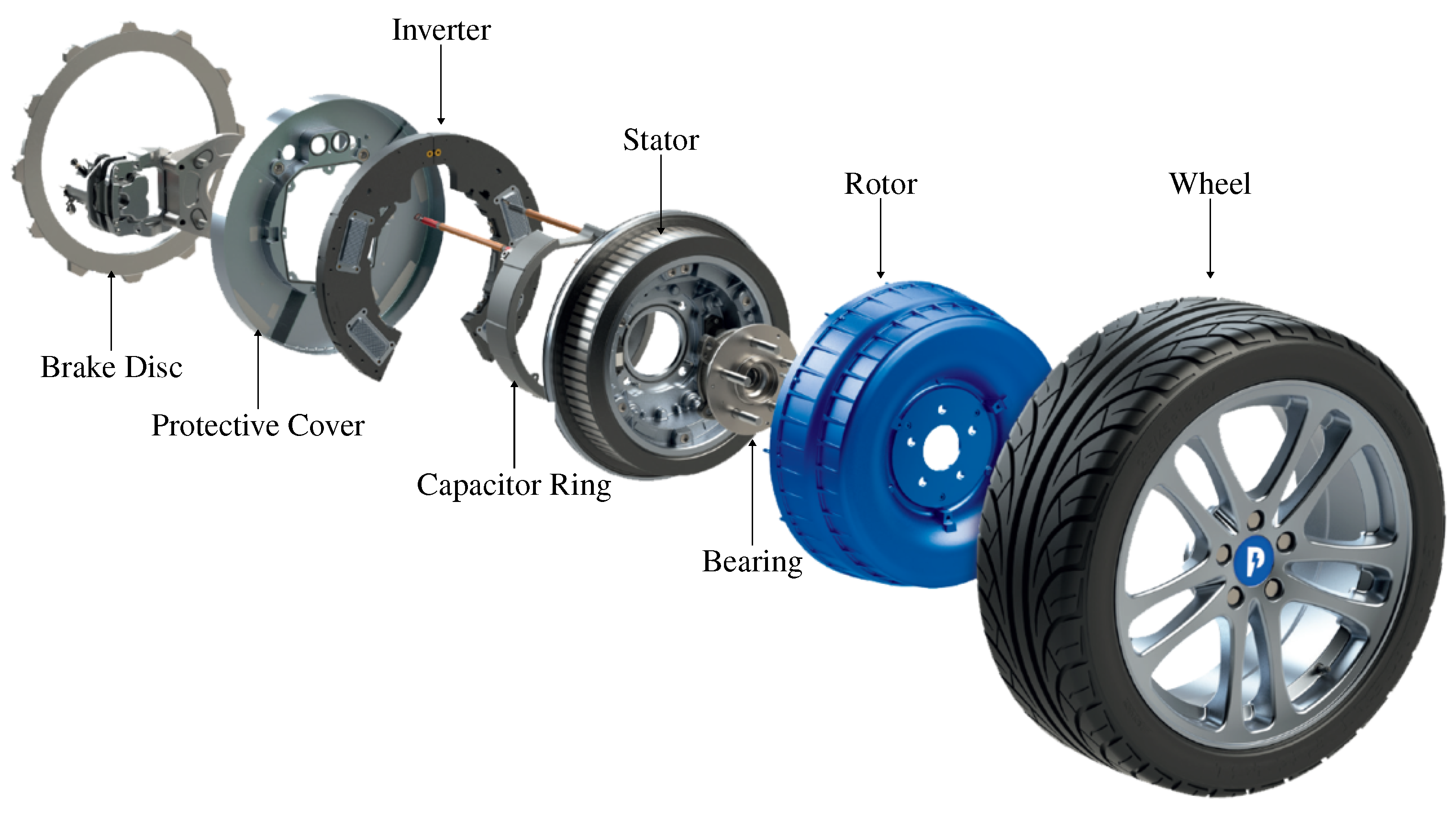
3. Integrated Power Electronics in IWMs
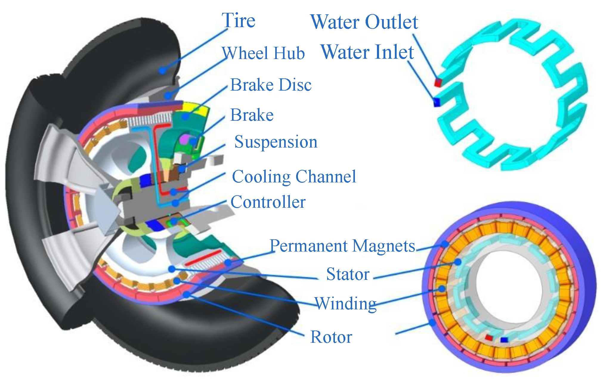
4. Cooling of IWMs
4.1. Air Cooling
4.2. Oil Cooling
4.3. Water Cooling
5. Control Methods Used for IWMs and IWM Driven EVs
5.1. Control of the IWMs
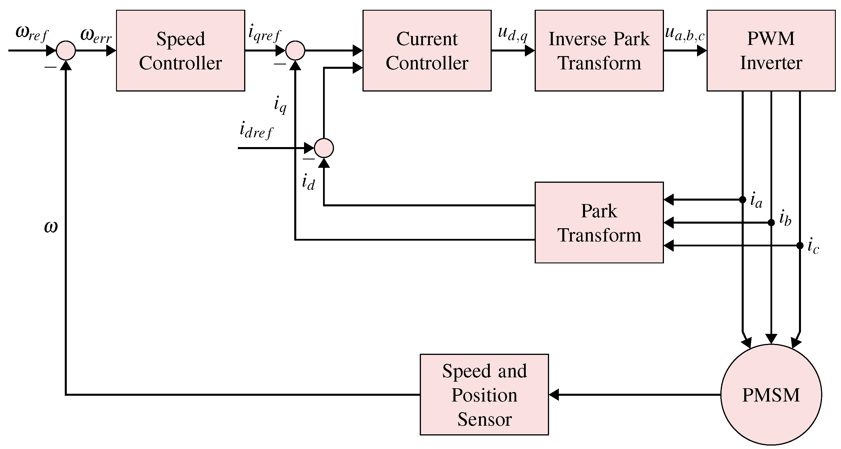
5.1.1. Field Oriented Control (FOC)
5.1.2. Direct Torque Control (DTC)
5.1.3. Model Predictive Control (MPC)
5.2. Control of Vehicle with IWMs: Torque Vectoring and Torque Distribution
- Non-linearity in the vehicle dynamics due to the coupling of longitudinal, lateral, and yaw dynamics, as well as the non-linear tire longitudinal and lateral characteristics;
- The issue of over-actuation occurs due to the fact that there are four control inputs (torques on four wheels) which exceed the number of states requiring control. As a result, it is necessary to allocate torque based on specified objectives.
- Active front steering (AFS) control: AFS offers an electronically controlled superimposition of an angle to the steering wheel angle, allowing for a continuous and driving-situation dependent adaptation of the steering characteristics. This additional degree of freedom enables the optimization of steering comfort, effort, and dynamics [102,103,104].
6. Mechanical Failures and Challenges in IWMs Driven EVs
- Increased unsprung mass results in poorer vehicle dynamics;
- Thermomechanical influences, caused by the variation in expansion of the materials in an assembly, which results in a subsequent stress-strain state;
- Sudden and unanticipated external impacts can cause the structural elasticity to become distorted;
- The effect of torque pulsation-related vibrations on acoustics and structural fatigue;
- Bearing system faults leading to mechanical breakdowns.;
- Static or dynamic eccentricity induced mechanical defects;
- Challenges for sealing of IWM.
6.1. Unsprung Mass
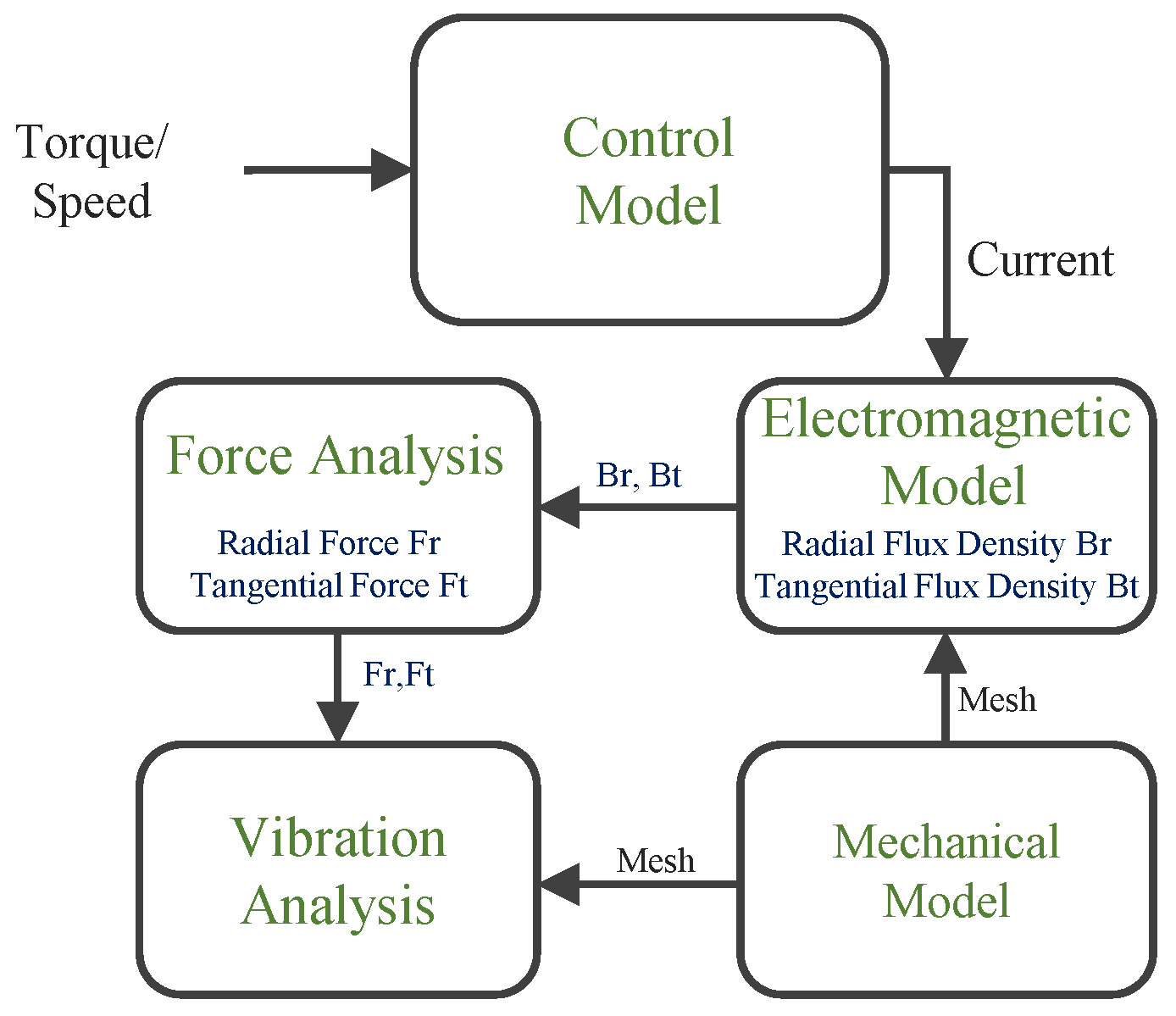
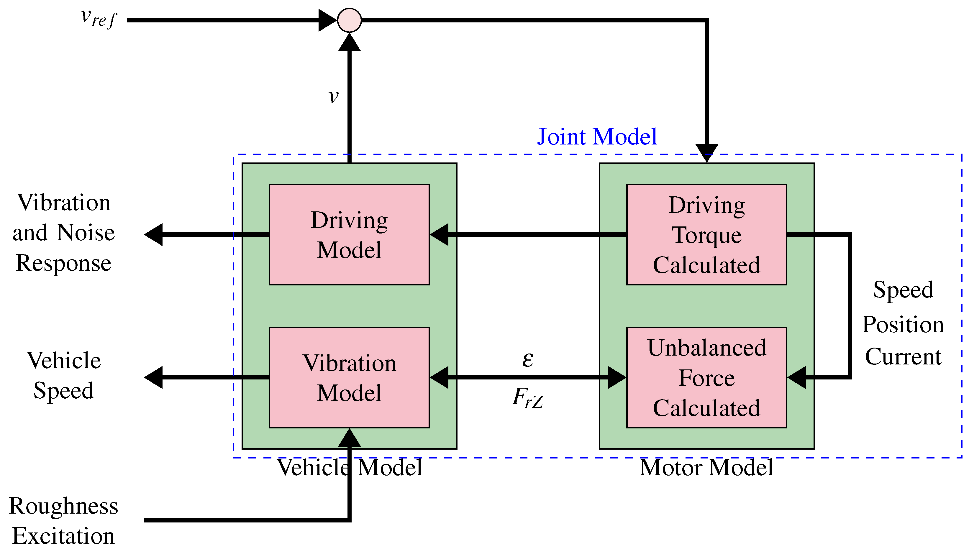
6.2. Vibrations Sources
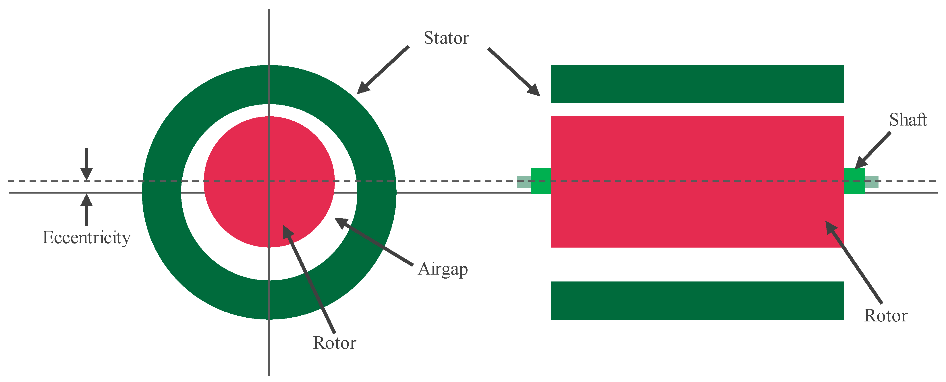
6.3. Eccentricity
6.4. Bearing Faults
6.5. Sealing
7. Next Trends
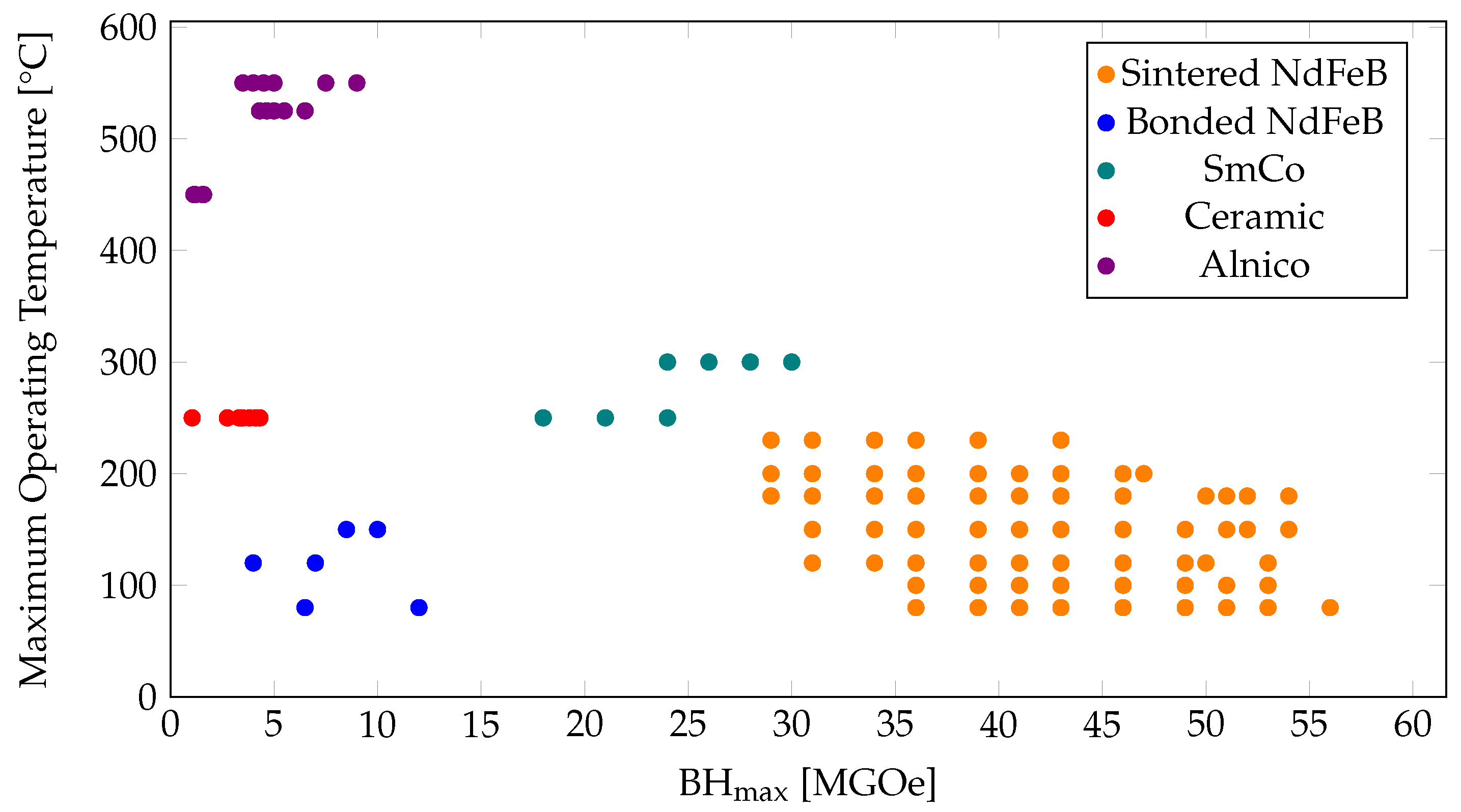
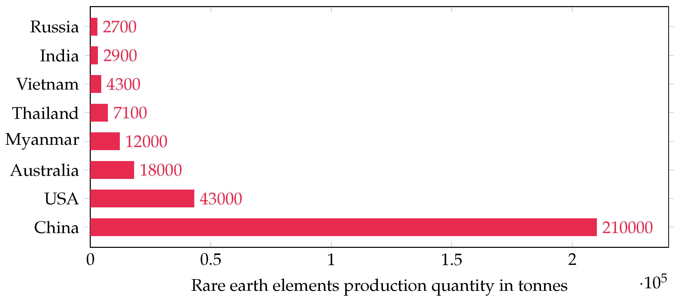
7.1. Magnet Price Crisis and Rare Earth Magnets Availability
- Ferrite magnets;
- Alnico magnets;
- Neodymium magnets;
- Samarium cobalt magnets.
- Remanence, B: measures the strength of the magnetic field;
- Coercivity, H: is the resistance of the material to being demagnetized;
- Maximum energy product (BHmax): is the density of magnetic energy is determined by the product of the maximum value of magnetic flux density (B) and magnetic field strength (H);
- Curie temperature: the temperature at which the material loses its magnetism completely;
- Maximum operating temperature: the normal operating range of magnet; below this temperature demagnetization is reversible.
7.2. Alternatives to RE Based IWMs
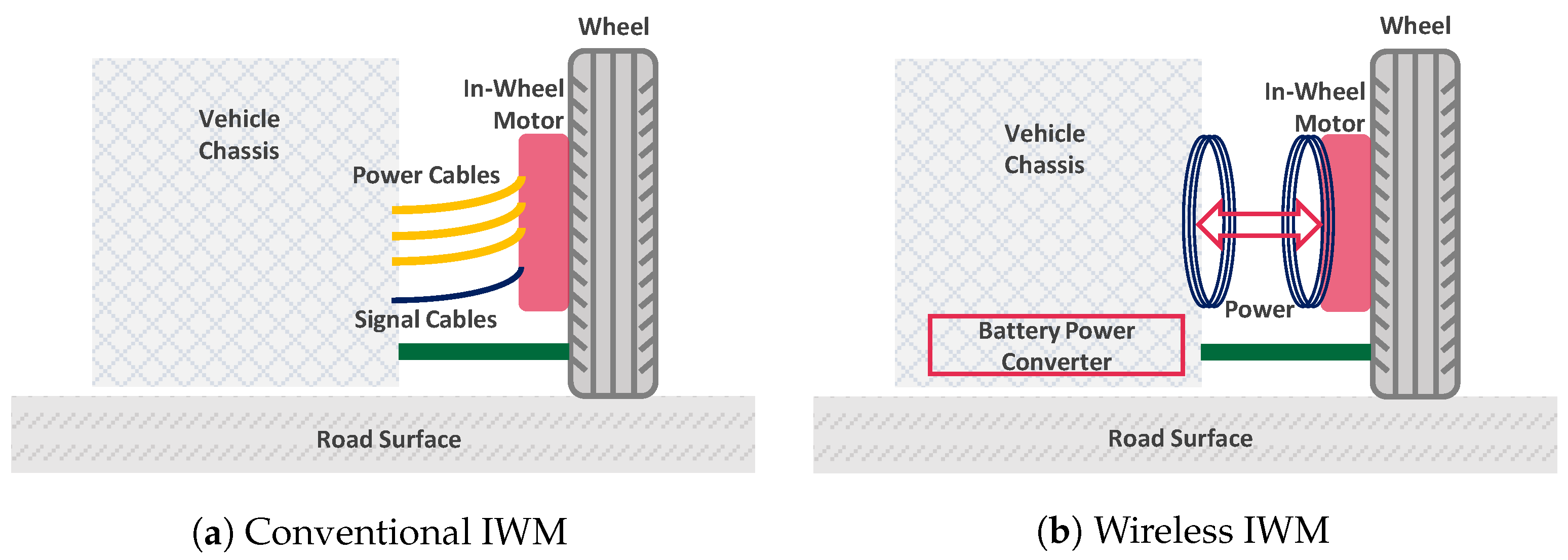
7.3. Wireless IWMs
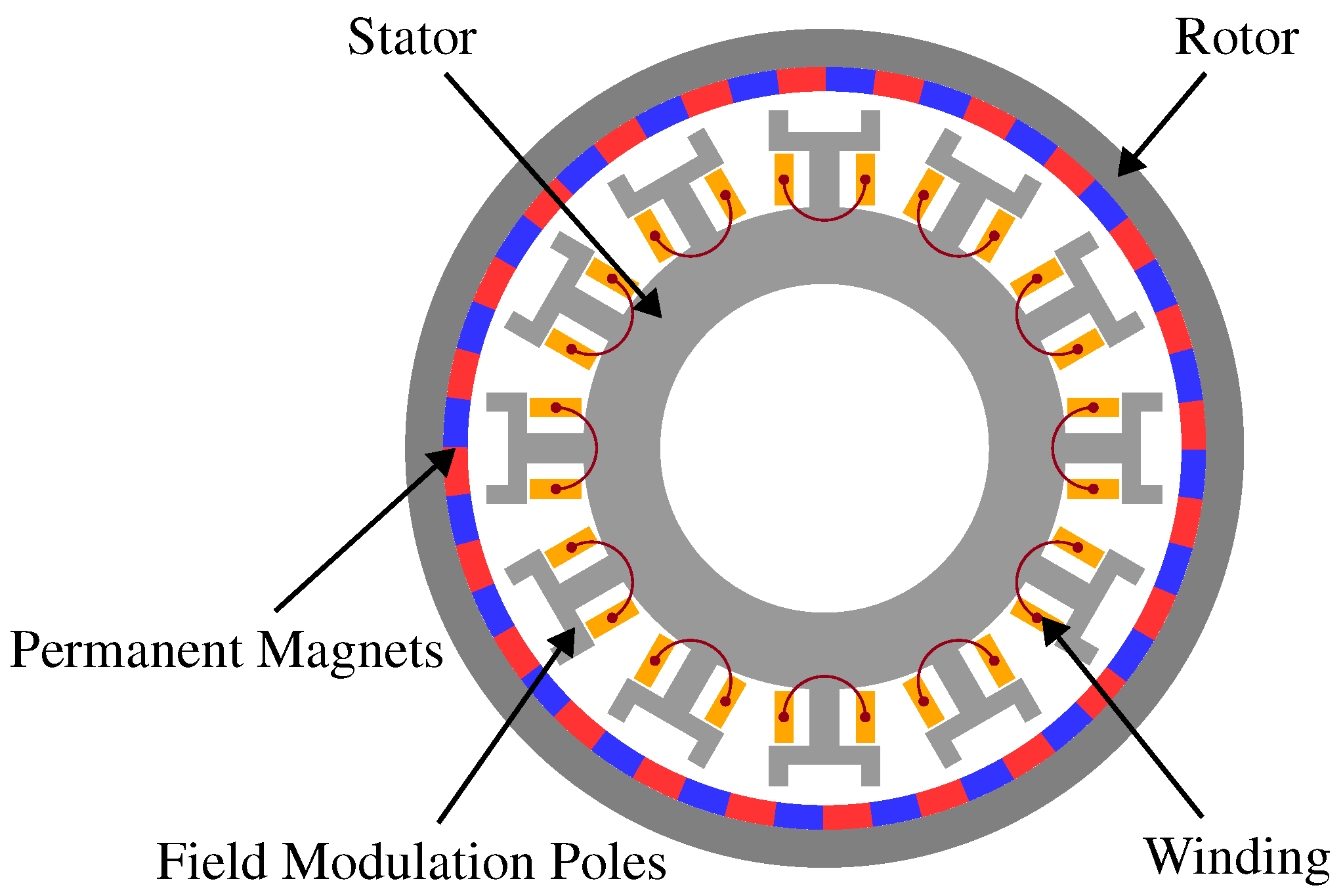
7.4. Field-Modulated Motors for IWM Driven EVs
8. Conclusions
Author Contributions
Funding
Data Availability Statement
Acknowledgments
Conflicts of Interest
Abbreviations
| AFM | Axial Flux Motor |
| AFIM | Axial Flux Induction Motor |
| AFPM | Axial Flux Permanent Magnet Motor |
| AF-SRM | Axial Flux Switched Reluctance Motor |
| BEV | Battery Electric Vehicle |
| CP | Consequent Pole |
| DTC | Direct Torque Control |
| DSSR | Double Stator Single Rotor |
| EU | European Union |
| EV | Electric Vehicle |
| FEA | Finite Element Analysis |
| FOC | Field Oriented Control |
| HEV | Hybrid Electric Vehicle |
| ICE | Internal Combustion Engine |
| IM | Induction Motor |
| IPMSM | Internal Permanent Magnet Synchronous Motor |
| IWM | In-Wheel Motor |
| IWM-DEV | In-Wheel Motor Driven Electric Vehicle |
| OR-IM | Outer Rotor Induction Motor |
| OR-PMSM | Outer Rotor Permanent Magnet Synchronous Motor |
| MGM | Magnetically Geared Motor |
| MGOe | Mega Gauss Oersted |
| MPC | Model Predictive Control |
| MSMR | Multi Stator Multi Rotor |
| NdFeB | Neodymium Iron Boron |
| NVH | Noise, Vibration and Harshness |
| PM | Permanent Magnet |
| PMSM | Permanent Magnet Synchronous Motor |
| RE | Rare Earth |
| RFM | Radial Flux Motor |
| SmCo | Samarium Cobalt |
| SSSR | Single Stator Single Rotor |
| SSDR | Single Stator Double Rotor |
| SVM | Space Vector Modulation |
| SRM | Switched Reluctance Motor |
| SynRM | Synchronous Reluctance Motor |
| TMD | Tuned Mass Damper |
| VPM | Vernier Permanent Magnet Motor |
| WPT | Wireless Power Transfer |
References
- Hawkins, T.R.; Gausen, O.M.; Strømman, A.H. Environmental impacts of hybrid and electric vehicles—A review. Int. J. Life Cycle Assess. 2012, 17, 997–1014. [Google Scholar] [CrossRef]
- Pg Abas, A.E.; Yong, J.; Mahlia, T.M.; Hannan, M.A. Techno-economic analysis and environmental impact of electric vehicle. IEEE Access 2019, 7, 98565–98578. [Google Scholar] [CrossRef]
- Albatayneh, A.; Assaf, M.N.; Alterman, D.; Jaradat, M. Comparison of the Overall Energy Efficiency for Internal Combustion Engine Vehicles and Electric Vehicles. Environ. Clim. Technol. 2020, 24, 669–680. [Google Scholar] [CrossRef]
- Krings, A.; Monissen, C. Review and trends in electric traction motors for battery electric and hybrid vehicles. In Proceedings of the 2020 International Conference on Electrical Machines, ICEM 2020, Gothenburg, Sweden, 23–26 August 2020; pp. 1807–1813. [Google Scholar] [CrossRef]
- Hecht, C.; Spreuer, K.G.; Figgener, J.; Sauer, D.U. Market Review and Technical Properties of Electric Vehicles in Germany. Vehicles 2022, 4, 903–916. [Google Scholar] [CrossRef]
- Burress, T.A.; Campbell, S.L.; Coomer, C.; Ayers, C.W.; Wereszczak, A.A.; Cunningham, J.P.; Marlino, L.D.; Seiber, L.E.; Lin, H.T. Evaluation of the 2010 Toyota Prius Hybrid Synergy Drive System; Technical Report; Oak Ridge National Lab: Oak Rigde, TN, USA, 2011. [Google Scholar] [CrossRef] [Green Version]
- Wellings, J.; Greenwood, D.; Coles, S.R. Understanding the Future Impacts of Electric Vehicles—An Analysis of Multiple Factors That Influence the Market. Vehicles 2021, 3, 851–871. [Google Scholar] [CrossRef]
- Sanguesa, J.A.; Torres-Sanz, V.; Garrido, P.; Martinez, F.J.; Marquez-Barja, J.M. A Review on Electric Vehicles: Technologies and Challenges. Smart Cities 2021, 4, 372–404. [Google Scholar] [CrossRef]
- Mierlo, J.V.; Berecibar, M.; Baghdadi, M.E.; De Cauwer, C.; Messagie, M.; Coosemans, T.; Jacobs, V.A.; Hegazy, O. Beyond the State of the Art of Electric Vehicles: A Fact-Based Paper of the Current and Prospective Electric Vehicle Technologies. World Electr. Veh. J. 2021, 12, 20. [Google Scholar] [CrossRef]
- Yong, J.Y.; Ramachandaramurthy, V.K.; Tan, K.M.; Mithulananthan, N. A review on the state-of-the-art technologies of electric vehicle, its impacts and prospects. Renew. Sustain. Energy Rev. 2015, 49, 365–385. [Google Scholar] [CrossRef]
- Zhao, Y.; Zhang, Y.; Zhao, Y. Stability control system for four-in-wheel-motor drive electric vehicle. In Proceedings of the 6th International Conference on Fuzzy Systems and Knowledge Discovery, FSKD 2009, Tianjin, China, 14–16 August 2009; Volume 4, pp. 171–175. [Google Scholar] [CrossRef]
- The History of Porsche Begins Electrically—Porsche Newsroom. Available online: https://newsroom.porsche.com/en/products/taycan/history-18563.html (accessed on 21 February 2023).
- 1900 Lohner-Porsche Mixte Voiturette—Images, Specifications and Information. Available online: https://www.ultimatecarpage.com/car/3456/Lohner-Porsche-Mixte-Voiturette.html (accessed on 24 February 2023).
- Biček, M.; Gotovac, G.; Miljavec, D.; Zupan, S. Mechanical Failure Mode Causes of In-Wheel Motors. Stroj. Vestn. J. Mech. Eng. 2015, 61, 74–85. [Google Scholar] [CrossRef] [Green Version]
- Cai, S.; Kirtley, J.L.; Lee, C.H. Critical Review of Direct-Drive Electrical Machine Systems for Electric and Hybrid Electric Vehicles. IEEE Trans. Energy Convers. 2022, 37, 2657–2668. [Google Scholar] [CrossRef]
- Aloeyi, E.F.; Ali, N.; Wang, Q. A Review of In-Wheel Motors for Electric Vehicle Propulsion. In Proceedings of the 2022 IEEE Transportation Electrification Conference and Expo, Asia-Pacific (ITEC Asia-Pacific), Haining, China, 28–31 October 2022; pp. 1–6. [Google Scholar] [CrossRef]
- Gong, J.; Zhao, B.; Huang, Y.; Semail, E.; Nguyen, N.K. Quantitative Comparisons of Outer-Rotor Permanent Magnet Machines of Different Structures/Phases for In-Wheel Electrical Vehicle Application. Energies 2022, 15, 6688. [Google Scholar] [CrossRef]
- Xue, X.D.; Cheng, K.W.; Ng, T.W.; Cheung, N.C. Multi-objective optimization design of in-wheel switched reluctance motors in electric vehicles. IEEE Trans. Ind. Electron. 2010, 57, 2980–2987. [Google Scholar] [CrossRef]
- Lucid Motors Tech Talk On Drive Unit & Motor—Lucid Insider Blog—Lucid Air & Lucid Motors News. Available online: https://www.lucidinsider.com/2022/09/13/lucid-motors-tech-talk-on-drive-unit-motor/ (accessed on 23 February 2023).
- Goli, C.S.; Manjrekar, M.; Essakiappan, S.; Sahu, P.; Shah, N. Landscaping and review of traction motors for electric vehicle applications. In Proceedings of the 2021 IEEE Transportation Electrification Conference and Expo, ITEC 2021, Chicago, IL, USA, 23–25 June 2021; pp. 162–168. [Google Scholar] [CrossRef]
- Porsche Taycan Finally Revealed. Available online: https://www.electrive.com/2019/09/04/porsche-taycan-finally-revealed/ (accessed on 23 February 2023).
- Wang, X.; Zhang, Z.; Gao, P.; Lu, H.; He, X. Design and Simulation Analysis of a Novel Outer Rotor IPM Motor Used in Electric Vehicles. In Proceedings of the 13th World Congress on Intelligent Control and Automation (WCICA), Changsha, China, 4–8 July 2018. [Google Scholar]
- Fan, Y.; Chen, S.; Tan, C.; Cheng, M. Design and investigation of a new outer-rotor IPM motor for EV and HEV in-wheel propulsion. In Proceedings of the 19th International Conference on Electrical Machines and Systems (ICEMS), Chiba, Japan, 13–16 November 2016. [Google Scholar]
- Ishii, S.; Hasegawa, Y.; Nakamura, K.; Ichinokura, O. Characteristics of Novel Flux Barrier Type Outer Rotor IPM Motor with Rare-earth and Ferrite Magnets. In Proceedings of the 2012 International Conference on Renewable Energy Research and Applications (ICRERA), Nagasaki, Japan, 11–14 November 2012. [Google Scholar] [CrossRef]
- Fornasiero, E.; Morandin, M.; Carraro, E.; Bianchi, N.; Bolognani, S. Outer Rotor IPM Generator with Wide Constant Power Region for Automotive Applications. In Proceedings of the 2014 IEEE Transportation Electrification Conference and Expo (ITEC), Dearborn, MI, USA, 15–18 June 2014. [Google Scholar] [CrossRef]
- Yao, Y.; Liu, C.; Lee, C.H. Quantitative comparisons of six-phase outer-rotor permanent-magnet brushless machines for electric vehicles. Energies 2018, 11, 2141. [Google Scholar] [CrossRef] [Green Version]
- Labak, A.; Kar, N.C. Outer rotor switched reluctance motor design for in-wheel drive of electric bus applications. In Proceedings of the 2012 20th International Conference on Electrical Machines, ICEM 2012, Marseille, France, 2–5 September 2012; pp. 418–423. [Google Scholar] [CrossRef]
- Yaling, W.; Yanliang, X.; Yufang, W.; Yun, Z. Outer-rotor switched reluctance motor and its control system used in electric vehicles. In Proceedings of the 2011 International Conference on Electrical Machines and Systems, ICEMS 2011, Beijing, China, 20–23 August 2011. [Google Scholar] [CrossRef]
- Boldea, I.; Tutelea, L.N.; Parsa, L.; Dorrell, D. Automotive electric propulsion systems with reduced or no permanent magnets: An overview. IEEE Trans. Ind. Electron. 2014, 61, 5696–5711. [Google Scholar] [CrossRef]
- Zhu, J.; Cheng, K.W.E.; Xue, X.; Zou, Y. Design of a New Enhanced Torque In-Wheel Switched Reluctance Motor with Divided Teeth for Electric Vehicles. IEEE Trans. Magn. 2017, 53, 2703849. [Google Scholar] [CrossRef]
- Qin, Y.; He, C.; Shao, X.; Du, H.; Xiang, C.; Dong, M. Vibration mitigation for in-wheel switched reluctance motor driven electric vehicle with dynamic vibration absorbing structures. J. Sound Vib. 2018, 419, 249–267. [Google Scholar] [CrossRef]
- Zhu, Y.; Zhao, C.; Zhang, J.; Gong, Z. Vibration control for electric vehicles with in-wheel switched reluctance motor drive system. IEEE Access 2020, 8, 7205–7216. [Google Scholar] [CrossRef]
- Jurca, F.N.; Martis, C. Analysis of outer rotor synchronous reluctance motor for low-speed applications. In Proceedings of the International Conference on Electical Drives and Power Electronics, Dubrovnik, Croatia, 4–6 October 2017; pp. 242–247. [Google Scholar] [CrossRef]
- Aghazadeh, H.; Afjei, E.; Siadatan, A. Sizing and detailed design procedure of external rotor synchronous reluctance machine. IET Electr. Power Appl. 2019, 13, 1105–1113. [Google Scholar] [CrossRef]
- Bozkurt, A.; Baba, A.F.; Oner, Y. Design of Outer-Rotor Permanent-Magnet-Assisted Synchronous Reluctance Motor for Electric Vehicles. Energies 2021, 14, 3739. [Google Scholar] [CrossRef]
- Al-ani, M. Multi-physics design and analyses of dual rotor synchronous reluctance machine. eTransportation 2021, 8, 100113. [Google Scholar] [CrossRef]
- Klima, P.; Rura, D.; Vitek, O. Analysis and Reduction of Eddy Current Losses in High-Speed Solid Outer Rotor Induction Machine. In Proceedings of the 2022 International Conference on Electrical Machines, ICEM 2022, Valencia, Spain, 5–8 September 2022; pp. 1022–1026. [Google Scholar] [CrossRef]
- Cha, H.R.; Jeong, T.W.; Im, D.Y.; Shin, K.J. Design of outer rotor type induction motor having high power density for in-wheel system. In Proceedings of the 15th International Conference on Electrical Machines and Systems (ICEMS), Sapporo, Japan, 21–24 October 2012. [Google Scholar]
- Abdo, T.M.; Adly, A.A. The Outer Solid Rotor Induction Motor as an Alternative for Electric Vehicle Traction Applications. In Proceedings of the 2022 Joint MMM-Intermag Conference, INTERMAG 2022, New Orleans, LA, USA, 10–14 January 2022. [Google Scholar] [CrossRef]
- Virlan, B.; Benelghali, S.; Simion, A.; Livadaru, L.; Outbib, R.; Munteanu, A. Induction motor with outer rotor and ring stator winding for Multispeed applications. IEEE Trans. Energy Convers. 2013, 28, 999–1007. [Google Scholar] [CrossRef]
- Rezazadeh, G.; Tahami, F.; Capolino, G.A.; Nasiri-Gheidari, Z.; Henao, H.; Sahebazamani, M. Improved Design of an Outer Rotor Six-Phase Induction Motor With Variable Turn Pseudo-Concentrated Windings. IEEE Trans. Energy Convers. 2022, 37, 1020–1029. [Google Scholar] [CrossRef]
- Virlan, B.; Benelghali, S.; Munteanu, A.; Simion, A.; Outbib, R. Multi-speed induction motor for direct drive applications. In Proceedings of the 2012 20th International Conference on Electrical Machines, ICEM 2012, Marseille, France, 2–5 September 2012; pp. 1928–1934. [Google Scholar] [CrossRef]
- Livadaru, L.; Munteanu, A.; Simion, A.; Cantemir, C.G. Design and finite element analysis of high-density torque induction motor for traction applications. In Proceedings of the 2015 9th International Symposium on Advanced Topics in Electrical Engineering, ATEE 2015, Bucharest, Romania, 7–9 May 2015; pp. 211–214. [Google Scholar] [CrossRef]
- Virlan, B.; Simion, A.; Livadaru, L.; Benelghali, S.; Outbib, R. Analysis of a three phase induction motor with outer rotor for multi-speed applications. In Proceedings of the 2012 20th International Conference on Electrical Machines, ICEM 2012, Marseille, France, 2–5 September 2012; pp. 411–417. [Google Scholar] [CrossRef]
- Technology—ProteanDrive. Available online: https://www.proteanelectric.com/technology/#overview (accessed on 10 February 2023).
- Elaphe Direct-Drive in-Wheel Motors. Available online: https://in-wheel.com/en/solutions-2/direct-drive-in-wheel-motors/ (accessed on 9 February 2023).
- PMW Dynamics In-Wheel XR Series Motors. Available online: https://www.pmwdynamics.com/in-wheel-motors/ (accessed on 10 February 2023).
- GEM Motors In-Wheel Motors and Electric Drive Solutions. Available online: https://www.gemmotors.si/products/#gem-g-3 (accessed on 10 February 2023).
- Endurance—Lordstown Motors. Available online: https://www.lordstownmotors.com/pages/endurance (accessed on 9 February 2023).
- Lordstown “Endurance”—The World’s First All-Electric Commercial Pickup Truck—Elaphe. Available online: https://in-wheel.com/en/news/lordstown-endurance-the-worlds-first-all-electric-commercial-pickup-truck/ (accessed on 1 January 2020).
- Deng, W.; Zuo, S. Axial force and vibroacoustic analysis of external-rotor axial-flux motors. IEEE Trans. Ind. Electron. 2018, 65, 2018–2030. [Google Scholar] [CrossRef]
- Hattori, A.; Noguchi, T.; Kamiyama, H. High-Torque Density Design of Small Motors for Automotive Applications with Double Axial-Air-Gap Structures. Energies 2022, 15, 7341. [Google Scholar] [CrossRef]
- Torkaman, H.; Ghaheri, A.; Keyhani, A. Axial flux switched reluctance machines: A comprehensive review of design and topologies. IET Electr. Power Appl. 2019, 13, 310–321. [Google Scholar] [CrossRef]
- Petrov, I.; Lindh, P.; Peng, W.Y.; Jang, C.S.; Yang, H.P.; Pyrhonen, J. Improvement of axial flux single-rotor single-stator induction machine performance by applying semi-magnetic wedges. In Proceedings of the 2016 22nd International Conference on Electrical Machines, ICEM 2016, Lausanne, Switzerland, 4–7 September 2016; pp. 1795–1800. [Google Scholar] [CrossRef]
- Arthur, B.P.B.; Baskaran, U. Improved air-gap flux in axial flux induction machine through shaping of radial slot opening. Sadhana Acad. Proc. Eng. Sci. 2020, 45, 1–12. [Google Scholar] [CrossRef]
- Arabul, F.K.; Senol, I.; Oner, Y. Performance Analysis of Axial-Flux Induction Motor with Skewed Rotor. Energies 2020, 13, 4991. [Google Scholar] [CrossRef]
- Nishanth, F.N.; Verdeghem, J.V.; Severson, E.L. Recent Advances in Analysis and Design of Axial Flux Permanent Magnet Electric Machines. In Proceedings of the 2021 IEEE Energy Conversion Congress and Exposition, ECCE 2021, Virtual, 10–14 October 2021; pp. 3745–3752. [Google Scholar] [CrossRef]
- Nobahari, A.; Darabi, A.; Hassannia, A. Various skewing arrangements and relative position of dual rotor of an axial flux induction motor, modelling and performance evaluation. IET Electr. Power Appl. 2018, 12, 575–580. [Google Scholar] [CrossRef]
- Parviainen, A.; Niemelä, M.; Pyrhönen, J. Modeling of axial flux permanent-magnet machines. IEEE Trans. Ind. Appl. 2004, 40, 1333–1340. [Google Scholar] [CrossRef]
- Ma, J.; Qu, R.; Li, J. Optimal design of axial flux switched reluctance motor for electric vehicle application. In Proceedings of the 2014 17th International Conference on Electrical Machines and Systems (ICEMS), Hangzhou, China, 22–25 October 2014; pp. 1860–1865. [Google Scholar] [CrossRef]
- Hao, Z.; Ma, Y.; Wang, P.; Luo, G.; Chen, Y. A Review of Axial-Flux Permanent-Magnet Motors: Topological Structures, Design, Optimization and Control Techniques. Machine 2022, 10, 1178. [Google Scholar] [CrossRef]
- High Power Electric Car Motor | High Torque E-Motor | Yasa 750 | YASA. Available online: https://www.yasa.com/products/yasa-750/ (accessed on 8 February 2023).
- Camilleri, R.; Woolmer, T.; Court, A.; McCulloch, M.D. Investigation into the temperature profile of a liquid cooled YASA© AFPM machine. IET Conf. Publ. 2012, 2012, 281. [Google Scholar] [CrossRef]
- Turntide Technologies Acquires Electric Vehicle Component Developer Avid Technology—Turntide Technologies. Available online: https://turntide.com/press/turntide-technologies-acquires-electric-vehicle-component-developer-avid-technology/ (accessed on 10 February 2023).
- Magnax—Yokeless Axial Flux Technology. Available online: https://www.magnax.com/ (accessed on 10 February 2023).
- Electrification—Turntide Technologies. Available online: https://turntide.com/technology/electrification/#ev-motors (accessed on 10 February 2023).
- EMRAX- E-MOTORS. Available online: https://emrax.com/e-motors/ (accessed on 10 February 2023).
- Lehr, M.; Reis, K.; Binder, A. Comparison of axial flux and radial flux machines for the use in wheel hub drives. Elektrotech. Informationstec. 2015, 132, 25–32. [Google Scholar] [CrossRef]
- Han, P.; Heins, G.; Zhang, Y.; Ionel, D.M. Integrated Modular Motor Drives Based on Multiphase Axial-flux PM Machines with Fractional-slot Concentrated Windings. In Proceedings of the 2021 IEEE International Electric Machines and Drives Conference, IEMDC 2021, Hartford, CT, USA, 17–20 May 2021. [Google Scholar] [CrossRef]
- Abebe, R.; Vakil, G.; Calzo, G.L.; Cox, T.; Lambert, S.; Johnson, M.; Gerada, C.; Mecrow, B. Integrated motor drives: State of the art and future trends. IET Electr. Power Appl. 2016, 10, 757–771. [Google Scholar] [CrossRef] [Green Version]
- Maerz, M.; Poech, M.; Schimanek, E.; Schletz, A. Mechatronic integration into the hybrid powertrain—The thermal challenge. In Proceedings of the International Conference Automotive Power Electronics (APE), Tegernsee, Germany, 4–6 October 2006. [Google Scholar]
- Lee, W.; Li, S.; Han, D.; Sarlioglu, B.; Minav, T.A.; Pietola, M. A Review of Integrated Motor Drive and Wide-Bandgap Power Electronics for High-Performance Electro-Hydrostatic Actuators. IEEE Trans. Transp. Electrif. 2018, 4, 684–693. [Google Scholar] [CrossRef]
- Wu, S.; Zhou, J.; Zhang, X.; Yu, J. Design and Research on High Power Density Motor of Integrated Motor Drive System for Electric Vehicles. Energies 2022, 15, 3542. [Google Scholar] [CrossRef]
- Zhang, B.; Song, Z.; Liu, S.; Huang, R.; Liu, C. Overview of Integrated Electric Motor Drives: Opportunities and Challenges. Energies 2022, 15, 8299. [Google Scholar] [CrossRef]
- Jahns, T.M.; Sarlioglu, B. The Incredible Shrinking Motor Drive: Accelerating the Transition to Integrated Motor Drives. IEEE Power Electron. Mag. 2020, 7, 18–27. [Google Scholar] [CrossRef]
- Mohamed, A.H.; Vansompel, H.; Sergeant, P. An Integrated Motor Drive with Enhanced Power Density Using Modular Converter Structure. In Proceedings of the 2021 IEEE International Electric Machines and Drives Conference, IEMDC 2021, Hartford, CT, USA, 17–20 May 2021. [Google Scholar] [CrossRef]
- Kim, S.C.; Kim, W.; Kim, M.S. Cooling performance of 25 kW in-wheel motor for electric vehicles. Int. J. Automot. Technol. 2013, 14, 559–567. [Google Scholar] [CrossRef]
- Winterborne, D.; Stannard, N.; Sjoberg, L.; Atkinson, G. An air-cooled yasa motor for in-wheel electric vehicle applications. In Proceedings of the 2019 IEEE International Electric Machines and Drives Conference, IEMDC 2019, San Diego, CA, USA, 12–15 May 2019; pp. 976–981. [Google Scholar] [CrossRef]
- Park, M.H.; Kim, S.C. Thermal characteristics and effects of oil spray cooling on in-wheel motors in electric vehicles. Appl. Therm. Eng. 2019, 152, 582–593. [Google Scholar] [CrossRef]
- Lim, D.H.; Kim, S.C. Thermal performance of oil spray cooling system for in-wheel motor in electric vehicles. Appl. Therm. Eng. 2014, 63, 577–587. [Google Scholar] [CrossRef]
- Saleem, A.; Hyeon Park, M.; Ambreen, T.; Chul Kim, S. Optimization of oil flow distribution inside the in-wheel motor assembly of electric vehicles for improved thermal performance. Appl. Therm. Eng. 2022, 201, 117753. [Google Scholar] [CrossRef]
- Acquaviva, A.; Skoog, S.; Thiringer, T. Design and Verification of In-Slot Oil-Cooled Tooth Coil Winding PM Machine for Traction Application. IEEE Trans. Ind. Electron. 2021, 68, 3719–3727. [Google Scholar] [CrossRef]
- Marcolini, F.; Donato, G.D.; Caricchi, F. Direct oil cooling of end-windings in torus-type axial-flux permanent-magnet machines. In Proceedings of the 2019 IEEE Energy Conversion Congress and Exposition, ECCE 2019, Baltimore, MD, USA, 29 September–3 October 2019; pp. 5645–5651. [Google Scholar] [CrossRef]
- Chattopadhyay, R.; Islam, M.S.; Jung, J.; Mikail, R.; Husain, I. Winding Embedded Liquid Cooling for Slotless Motors in Transportation Applications. IEEE Trans. Ind. Appl. 2022, 58, 7110–7120. [Google Scholar] [CrossRef]
- Liang, P.; Chai, F.; Shen, K.; Liu, W. Water Jacket and Slot Optimization of a Water-Cooling Permanent Magnet Synchronous In-Wheel Motor. IEEE Trans. Ind. Appl. 2021, 57, 2431–2439. [Google Scholar] [CrossRef]
- Satrústegui, M.; Martinez-Iturralde, M.; Ramos, J.C.; Gonzalez, P.; Astarbe, G.; Elosegui, I. Design criteria for water cooled systems of induction machines. Appl. Therm. Eng. 2017, 114, 1018–1028. [Google Scholar] [CrossRef]
- Fan, P.; Fan, D.; Zhu, X.; Xiang, Z.; Zhou, X. Research on Heat Dissipation Characteristics of PM in-wheel Motor Using Electrical-Thermal Bi-Directional Coupling Method. In Proceedings of the 2022 IEEE Transportation Electrification Conference and Expo, Asia-Pacific, ITEC Asia-Pacific 2022, Haining, China, 28–31 October 2022. [Google Scholar] [CrossRef]
- Wang, Q.; Li, R.; Zhao, Z.; Liang, K.; Xu, W.; Zhao, P. Temperature Field Analysis and Cooling Structure Optimization for Integrated Permanent Magnet In-Wheel Motor Based on Electromagnetic-Thermal Coupling. Energies 2023, 16, 1527. [Google Scholar] [CrossRef]
- Pillay, P.; Krishnan, R. Modeling, Simulation, and Analysis of Permanent-Magnet Motor Drives, Part I: The Permanent-Magnet Synchronous Motor Drive. IEEE Trans. Ind. Appl. 1989, 25, 265–273. [Google Scholar] [CrossRef]
- Bida, V.M.; Samokhvalov, D.V.; Al-Mahturi, F.S. PMSM vector control techniques—A survey. In Proceedings of the 2018 IEEE Conference of Russian Young Researchers in Electrical and Electronic Engineering, ElConRus 2018, St. Petersburg, Russia, 29 January–1 February 2018; pp. 577–581. [Google Scholar] [CrossRef]
- Guo, Z.; Zhang, J.; Sun, Z.; Zheng, C. Indirect Field Oriented Control of Three-phase Induction Motor Based on Current-source Inverter. Procedia Eng. 2017, 174, 588–594. [Google Scholar] [CrossRef]
- Pedrosa, D.; Carvalho, J.; Goncalves, H.; Monteiro, V.; Fernandes, A.; Afonso, J.L. Field oriented control of an axial flux permanent magnet synchronous motor for traction solutions. In Proceedings of the IECON (Industrial Electronics Conference), Dallas, TX, USA, 29 October–1 November 2014; pp. 1466–1472. [Google Scholar] [CrossRef] [Green Version]
- Pedrosa, D.; Peixoto, H.; Goncalves, H.; Martins, J.S.; Couto, C.; Afonso, J.L. FPGA field oriented control of an Axial Flux motor-in-wheel. In Proceedings of the IECON (Industrial Electronics Conference), Dallas, TX, USA, 29 October–1 November 2014; pp. 594–600. [Google Scholar] [CrossRef] [Green Version]
- Buja, G.S.; Kazmierkowski, M.P. Direct torque control of PWM inverter-fed AC motors—A survey. IEEE Trans. Ind. Electron. 2004, 51, 744–757. [Google Scholar] [CrossRef]
- Aktas, M.; Awaili, K.; Ehsani, M.; Arisoy, A. Direct torque control versus indirect field-oriented control of induction motors for electric vehicle applications. Eng. Sci. Technol. Int. J. 2020, 23, 1134–1143. [Google Scholar] [CrossRef]
- Malyshev, A.; Ivanov, A. Direct Torque Control of the Axial Flux Permanent Magnet Motor. In Proceedings of the 13th International IEEE Scientific and Technical Conference Dynamics of Systems, Mechanisms and Machines, Dynamics 2019, Omsk, Russia, 5–7 November 2019. [Google Scholar] [CrossRef]
- Lin, C.; Liang, S.; Chen, J.; Gao, X. A multi-objective optimal torque distribution strategy for four in-wheel-motor drive electric vehicles. IEEE Access 2019, 7, 64627–64640. [Google Scholar] [CrossRef]
- Zhou, H.; Jia, F.; Jing, H.; Liu, Z.; Güvenç, L. Coordinated Longitudinal and Lateral Motion Control for Four Wheel Independent Motor-Drive Electric Vehicle. IEEE Trans. Veh. Technol. 2018, 67, 3782–3790. [Google Scholar] [CrossRef]
- Cai, L.; Liao, Z.; Wei, S.; Li, J. Novel Direct Yaw Moment Control of Multi-Wheel Hub Motor Driven Vehicles for Improving Mobility and Stability. IEEE Trans. Ind. Appl. 2022, 59, 591–600. [Google Scholar] [CrossRef]
- Tristano, M.; Lenzo, B.; Xu, X.; Forrier, B.; D’Hondt, T.; Risaliti, E.; Wilhelm, E. Real-time implementation of yaw rate and sideslip control through individual wheel torques. In Proceedings of the 2022 IEEE Vehicle Power and Propulsion Conference, VPPC 2022, Merced, CA, USA, 1–4 November 2022. [Google Scholar] [CrossRef]
- Asiabar, A.N.; Kazemi, R. A direct yaw moment controller for a four in-wheel motor drive electric vehicle using adaptive sliding mode control. Proc. Inst. Mech. Eng. Part K: J. Multi-Body Dyn. 2019, 233, 549–567. [Google Scholar] [CrossRef]
- Oraby, W.A.H.; El-Demerdash, S.M.; Selim, A.M.; Faizz, A.; Crolla, D.A. Improvement of Vehicle Lateral Dynamics by Active Front Steering Control. SAE Trans. 2004, 113, 1101–1110. [Google Scholar]
- Cui, F.L.; Ge, P.S.; Wang, Y.; Zhang, T. Active Front Steering Controller for Distributed Drive Electric Vehicles based on Sliding Mode Control. In Proceedings of the 2022 6th CAA International Conference on Vehicular Control and Intelligence, CVCI 2022, Nanjing, China, 28–30 October 2022. [Google Scholar] [CrossRef]
- Tian, T.; Fang, L.; Ding, S.; Zheng, W.X. Adaptive Fuzzy Sliding Mode Control for Active Front Steering System. In Proceedings of the Chinese Control Conference, CCC, Shenyang, China, 27–29 July 2020; pp. 358–363. [Google Scholar] [CrossRef]
- Wang, L.; Liu, G.; Zhang, D.; Miao, P. Integrated control of active front steering and direct yaw moment for multi-wheel independently driven electric vehicles. In Proceedings of the 2013 International Conference on Electrical Machines and Systems, ICEMS 2013, Busan, Republic of Korea, 26–29 October 2013; pp. 2301–2304. [Google Scholar] [CrossRef]
- Li, S.; Yang, Z. AFS/DYC Control of In-Wheel Motor Drive Electric Vehicle with Adaptive Tire Cornering Stiffness. In Proceedings of the 2022 6th CAA International Conference on Vehicular Control and Intelligence, CVCI 2022, Nanjing, China, 28–30 October 2022. [Google Scholar] [CrossRef]
- Guo, J.; Luo, Y.; Li, K. An adaptive hierarchical trajectory following control approach of autonomous four-wheel independent drive electric vehicles. IEEE Trans. Intell. Transp. Syst. 2018, 19, 2482–2492. [Google Scholar] [CrossRef]
- Liu, H.; Liu, C.; Han, L.; Xiang, C. Handling and Stability Integrated Control of AFS and DYC for Distributed Drive Electric Vehicles Based on Risk Assessment and Prediction. IEEE Trans. Intell. Transp. Syst. 2022, 23, 23148–23163. [Google Scholar] [CrossRef]
- Xu, Y.; Jiang, L.; Wei, B.; Qiu, L. An Optimal Torque Distribution Strategy for Four-Motorized-Wheel Electric Vehicle Considering Energy Conversation. IEEE Access 2020, 8, 135975–135988. [Google Scholar] [CrossRef]
- He, S.; Fan, X.; Wang, Q.; Chen, X.; Zhu, S. Review on Torque Distribution Scheme of Four-Wheel In-Wheel Motor Electric Vehicle. Machines 2022, 10, 619. [Google Scholar] [CrossRef]
- Lin, C.; Xu, Z. Wheel Torque Distribution of Four-Wheel-Drive Electric Vehicles Based on Multi-Objective Optimization. Energies 2015, 8, 3815–3831. [Google Scholar] [CrossRef] [Green Version]
- Saiteja, P.; Ashok, B.; Wagh, A.S.; Farrag, M.E. Critical review on optimal regenerative braking control system architecture, calibration parameters and development challenges for EVs. Int. J. Energy Res. 2022, 46, 20146–20179. [Google Scholar] [CrossRef]
- Guo, L.; Xu, H.; Zou, J.; Jie, H.; Zheng, G. Torque Distribution Strategy of Four-Wheel Independent Drive Electric Vehicle Based on Optimal Energy Consumption. In Proceedings of the 2020 IEEE 3rd International Conference on Electronics Technology, ICET 2020, Chengdu, China, 8–11 May 2020; pp. 252–256. [Google Scholar] [CrossRef]
- De Klerk, M.L.; Saha, A.K. A Comprehensive Review of Advanced Traction Motor Control Techniques Suitable for Electric Vehicle Applications. IEEE Access 2021, 9, 125080–125108. [Google Scholar] [CrossRef]
- Liang, J.; Feng, J.; Fang, Z.; Lu, Y.; Yin, G.; Mao, X.; Wu, J.; Wang, F. An Energy-oriented Torque-vector Control Framework for Distributed Drive Electric Vehicles. IEEE Trans. Transp. Electrif. 2023. [Google Scholar] [CrossRef]
- Sun, X.; Shi, Z.; Cai, Y.; Lei, G.; Guo, Y.; Zhu, J. Driving-Cycle-Oriented Design Optimization of a Permanent Magnet Hub Motor Drive System for a Four-Wheel-Drive Electric Vehicle. IEEE Trans. Transp. Electrif. 2020, 6, 1115–1125. [Google Scholar] [CrossRef]
- Shi, Z.; Sun, X.; Lei, G.; Tian, X.; Guo, Y.; Zhu, J. Multiobjective Optimization of a Five-Phase Bearingless Permanent Magnet Motor Considering Winding Area. IEEE/ASME Trans. Mechatronics 2022, 27, 2657–2666. [Google Scholar] [CrossRef]
- Sun, X.; Xu, N.; Yao, M. Sequential Subspace Optimization Design of a Dual Three-Phase Permanent Magnet Synchronous Hub Motor Based on NSGA III. IEEE Trans. Transp. Electrif. 2023, 9, 622–630. [Google Scholar] [CrossRef]
- Anderson, M.J. Unsprung Mass with In-Wheel Motors-Myths and Realities. 2010. Available online: https://www.proteanelectric.com/f/2018/04/protean-Services3.pdf (accessed on 20 February 2023).
- Nie, S.; Zhuang, Y.; Chen, F.; Wang, Y.; Liu, S. A method to eliminate unsprung adverse effect of in-wheel motor-driven vehicles. J. Low Freq. Noise Vib. Act. Control. 2018, 37, 955–976. [Google Scholar] [CrossRef] [Green Version]
- Quynh, L.V.; Cuong, B.V.; Liem, N.V.; Long, L.X.; Dung, P.T.T. Effect of in-wheel motor suspension system on electric vehicle ride comfort. Vibroeng. Procedia 2019, 29, 148–152. [Google Scholar] [CrossRef] [Green Version]
- Zhao, Z.; Taghavifar, H.; Du, H.; Qin, Y.; Dong, M.; Gu, L. In-Wheel Motor Vibration Control for Distributed-Driven Electric Vehicles: A Review. IEEE Trans. Transp. Electrif. 2021, 7, 2864–2880. [Google Scholar] [CrossRef]
- Li, Z.; Zheng, L.; Ren, Y.; Li, Y.; Xiong, Z. Multi-objective optimization of active suspension system in electric vehicle with In-Wheel-Motor against the negative electromechanical coupling effects. Mech. Syst. Signal Process. 2019, 116, 545–565. [Google Scholar] [CrossRef]
- Yu, Y.; Zhao, L.; Zhou, C. Influence of Rotor-Bearing Coupling Vibration on Dynamic Behavior of Electric Vehicle Driven by In-Wheel Motor. IEEE Access 2019, 7, 63540–63549. [Google Scholar] [CrossRef]
- Biček, M.; Connes, R.; Omerović, S.; Gündüz, A.; Kunc, R.; Zupan, S. The Bearing Stiffness Effect on In-Wheel Motors. Sustainability 2020, 12, 4070. [Google Scholar] [CrossRef]
- Biček, M.; Lampič, G.; Zupan, S.; Obrul, B.; Gotovac, G.; Štefe, B.; Valentinčič, J. High torque in-wheel motors for rescue vehicles. In Proceedings of the Innovative Automotive Technology—IAT, Nova Gorica, Slovenia, 12–13 April 2012; pp. 1–14. [Google Scholar]
- Biček, M.; Pepelnjak, T.; Pušavec, F. Production aspect of direct drive in-wheel motors. Procedia CIRP 2019, 81, 1278–1283. [Google Scholar] [CrossRef]
- Biček, M.; Kunc, R.; Zupan, S. Mechanical Impact on In-Wheel Motor’s Performance. J. Mech. 2017, 33, 607–618. [Google Scholar] [CrossRef]
- Galeazzi, A.; Roberts, G. Influence of wheel bearing performance on In-wheel motor advanced applications. In Proceedings of the 2013 World Electric Vehicle Symposium and Exhibition, EVS 2014, Barcelona, Spain, 17–20 November 2013. [Google Scholar] [CrossRef]
- Kostic Perovic, D. Making the Impossible, Possible—Overcoming the Design Challenges of In Wheel Motors. World Electr. Veh. J. 2012, 5, 514–519. [Google Scholar] [CrossRef] [Green Version]
- Wheel Hub Motor and Method for Sealing a Wheel Hub Motor. 2013. Available online: https://patents.google.com/patent/WO2014108231A2/en (accessed on 23 February 2023).
- Materials and Grades—Amazing Magnets. Available online: https://amazingmagnets.com/magnetic-grade-chart/ (accessed on 23 February 2023).
- Gauß, R.; Burkhardt, C.; Carencotte, F.; Gasparon, M.; Gutfleisch, O.; Higgins, I.; Karajić, M.; Klossek, A.; Mäkinen, M.; Schäfer, B.; et al. Rare Earth Magnets and Motors: A European Call for Action; Technical Report; European Raw Materials Alliance: Berlin, Germany, 2021. [Google Scholar]
- Cui, J.; Kramer, M.; Zhou, L.; Liu, F.; Gabay, A.; Hadjipanayis, G.; Balasubramanian, B.; Sellmyer, D. Current progress and future challenges in rare-earth-free permanent magnets. Acta Mater. 2018, 158, 118–137. [Google Scholar] [CrossRef]
- Rare Earths: Mine Production Top Countries 2022 | Statista. Available online: https://www.statista.com/statistics/268011/top-countries-in-rare-earth-mine-production/ (accessed on 23 February 2023).
- refreedrive | Rare Earth Free E-Drives Featuring Low Cost Manufacturing. Available online: https://www.refreedrive.eu/ (accessed on 21 February 2023).
- Fujimoto, H.; Shimizu, O.; Nagai, S.; Fujita, T.; Gunji, D.; Ohmori, Y. Development of wireless in-wheel motors for dynamic charging: From 2nd to 3rd generation. In Proceedings of the 2020 IEEE PELS Workshop on Emerging Technologies: Wireless Power Transfer, WoW 2020, Seoul, Republic of Korea, 15–19 November 2020; pp. 56–61. [Google Scholar] [CrossRef]
- Chen, Y.; Fu, W.; Weng, X. A Concept of General Flux-Modulated Electric Machines Based on a Unified Theory and Its Application to Developing a Novel Doubly-Fed Dual-Stator Motor. IEEE Trans. Ind. Electron. 2017, 64, 9914–9923. [Google Scholar] [CrossRef]
- Ruiz-Ponce, G.; Arjona, M.A.; Hernandez, C.; Escarela-Perez, R. A Review of Magnetic Gear Technologies Used in Mechanical Power Transmission. Energies 2023, 16, 1721. [Google Scholar] [CrossRef]
- Jing, L.; Gong, J.; Huang, Z.; Ben, T.; Huang, Y. A New Structure for the Magnetic Gear. IEEE Access 2019, 7, 75550–75555. [Google Scholar] [CrossRef]
- Li, W.; Chau, K.T.; Jiang, J.Z. Application of linear magnetic gears for pseudo-direct-drive oceanic wave energy harvesting. IEEE Trans. Magn. 2011, 47, 2624–2627. [Google Scholar] [CrossRef] [Green Version]
- Atallah, K.; Calverley, S.D.; Howe, D. Design, analysis and realisation of a high-performance magnetic gear. IEE Proc. Electr. Power Appl. 2004, 151, 135–143. [Google Scholar] [CrossRef]
- Gardner, M.C.; Jack, B.E.; Johnson, M.; Toliyat, H.A. Comparison of Surface Mounted Permanent Magnet Coaxial Radial Flux Magnetic Gears Independently Optimized for Volume, Cost, and Mass. IEEE Trans. Ind. Appl. 2018, 54, 2237–2245. [Google Scholar] [CrossRef]
- Magnetic Geared Machine | HQ Magnet. Available online: https://hq-magnet.com/magnetic-geared-machine/ (accessed on 23 February 2023).
- Wu, F.; El-Refaie, A.M. Permanent magnet vernier machine: A review. IET Electr. Power Appl. 2019, 13, 127–137. [Google Scholar] [CrossRef]
- Li, D.; Qu, R.; Li, J.; Xu, W. Consequent-Pole Toroidal-Winding Outer-Rotor Vernier Permanent-Magnet Machines. IEEE Trans. Ind. Appl. 2015, 51, 4470–4481. [Google Scholar] [CrossRef]
- Lee, C.H.; Angle, M.; Bhalla, K.K.; Qasim, M.; Mei, J.; Mohammadi, S.; Iyer, K.L.V.; Sinkular, J.J.; Kirtley, J.L. Quantitative Comparison of Vernier Permanent-Magnet Motors with Interior Permanent-Magnet Motor for Hybrid Electric Vehicles. Energies 2018, 11, 2546. [Google Scholar] [CrossRef] [Green Version]
- Shafiei, S.; Noroozi, M.A.; Milimonfared, J.; Lesani, H. Performance Comparison of Outer Rotor Permanent Magnet Vernier Motor for Direct Drive Systems. In Proceedings of the 2020 11th Power Electronics, Drive Systems, and Technologies Conference, PEDSTC 2020, Tehran, Iran, 4–6 February 2020. [Google Scholar] [CrossRef]
- Hosoya, R.; Shimomura, S. Apply to in-wheel machine of permanent magnet vernier machine using NdFeB bonded magnet Fundamental study. In Proceedings of the 8th International Conference on Power Electronics—ECCE Asia: “Green World with Power Electronics”, ICPE 2011-ECCE Asia, Jeju, Republic of Korea, 30 May–3 June 2011; pp. 2208–2215. [Google Scholar] [CrossRef]
- Wu, W.; Xu, L.; Liu, B. Design, Analysis, and Optimization of Permanent Magnet Vernier Machines Considering Rotor Losses. Energies 2022, 15, 1502. [Google Scholar] [CrossRef]
- Li, J.; Wu, D.; Zhang, X.; Gao, S. A new permanent-magnet vernier in-wheel motor for electric vehicles. In Proceedings of the 2010 IEEE Vehicle Power and Propulsion Conference, VPPC 2010, Lille, France, 1–3 September 2010. [Google Scholar] [CrossRef]
- Zhu, X.; Zhao, W.; Zhu, J.; Bian, F. A high power factor fault-tolerant vernier permanent-magnet machine. AIP Adv. 2017, 7, 056622. [Google Scholar] [CrossRef] [Green Version]


| Motor Type | Power [kW] | Torque [Nm] | Speed (Peak) [RPM] | |
|---|---|---|---|---|
| Nissan Hypermini | IPMSM | 24 | 130 | 6700 |
| Toyota Prius 2004 | IPMSM | 50 | 400 | 6000 |
| Toyota Camry | IPMSM | 70 | 270 | 14,000 |
| Lexus LS 600h | IPMSM | 110 | 300 | 10,230 |
| Toyota Prius 2010 | IPMSM | 60 | 207 | 14,000 |
| Nissan Leaf 2012 | PMSynRM | 80 | 280 | 10,390 |
| Honda Accord | IPMSM | 125 | 110 | 8000 |
| Chevy Volt | PMSynRM | 112 | 400 | - |
| BMW i3 | PMSynRM | 125 | 250 | 11,400 |
| Chevy Bolt | PMSynRM | 150 | 360 | 8810 |
| Toyota Prius 2017 | PMSynRM | 53 | - | 17,000 |
| Tesla Model 3 Front | IM | 145 | - | 18,100 |
| Tesla Model 3 Rear | PMSynRM | 285 | - | 18,100 |
| Porsche Taycan Turbo S | PMSynRM | 560 | - | - |
| Jaguar i-pace | PMSynRM | 294 | 696 | 13,000 |
| Lucid Air | IPMSM | 500 | - | - |
| Unit | Protean Pd18 | Elaphe L1500 | PMW Dynamics XR32-13 | GEM Motors G3 | |
|---|---|---|---|---|---|
| DC Link Voltage | V | 400 | 370 | 100 | 48 |
| Continuous Torque | Nm | 650 | 650 | 300 | 370 |
| Peak Torque | Nm | 1250 | 1500 | 577 | 500 |
| Continuous Power | kW | 60 | 77 | 5.87 | 15 |
| Peak Power | kW | 80 | 110 | - | 20 |
| Maximum Speed | RPM | 1600 | 1480 | 2000 | 1000 |
| Peak Efficiency | [%] | 93 | - | - | 91 |
| Mass | kg | 36 | 34.8 | 32 | 27 |
| Cooling | - | Water | Water | Water | Forced Air |
| References | [45] | [46] | [47] | [48] |
| Unit | YASA 750R | Magnax AXF275 | Turntide EVO AF130 | EMRAX 208 | |
|---|---|---|---|---|---|
| DC Link Voltage | [V] | 700 | - | 600 | 580 |
| Continuous Torque | [Nm] | 400 | 260 | 145 | 90 |
| Peak Torque | [Nm] | 790 | 520 | 350 | 150 |
| Continuous Power | [kW] | 70 | 150 | 64 | 56 |
| Peak Power | [kW] | 100 | 300 | 140 | 86 |
| Maximum Speed | [RPM] | 3250 | 8000 | 8000 | 7000 |
| Peak Efficiency | [%] | - | 95 | 98 | 96 |
| Peak Power Density | [kW/kg] | 5 | 12.5 | 10 | 8.3 |
| Mass | [kg] | 37 | 24 | 30.5 | 10.3 |
| Cooling | - | Water-Cooled | Water-Cooled | Water/Glycol Cooled | Air + Water |
| References | [62] | [65] | [66] | [67] |
Disclaimer/Publisher’s Note: The statements, opinions and data contained in all publications are solely those of the individual author(s) and contributor(s) and not of MDPI and/or the editor(s). MDPI and/or the editor(s) disclaim responsibility for any injury to people or property resulting from any ideas, methods, instructions or products referred to in the content. |
© 2023 by the authors. Licensee MDPI, Basel, Switzerland. This article is an open access article distributed under the terms and conditions of the Creative Commons Attribution (CC BY) license (https://creativecommons.org/licenses/by/4.0/).
Share and Cite
Deepak, K.; Frikha, M.A.; Benômar, Y.; El Baghdadi, M.; Hegazy, O. In-Wheel Motor Drive Systems for Electric Vehicles: State of the Art, Challenges, and Future Trends. Energies 2023, 16, 3121. https://doi.org/10.3390/en16073121
Deepak K, Frikha MA, Benômar Y, El Baghdadi M, Hegazy O. In-Wheel Motor Drive Systems for Electric Vehicles: State of the Art, Challenges, and Future Trends. Energies. 2023; 16(7):3121. https://doi.org/10.3390/en16073121
Chicago/Turabian StyleDeepak, Kritika, Mohamed Amine Frikha, Yassine Benômar, Mohamed El Baghdadi, and Omar Hegazy. 2023. "In-Wheel Motor Drive Systems for Electric Vehicles: State of the Art, Challenges, and Future Trends" Energies 16, no. 7: 3121. https://doi.org/10.3390/en16073121