Article

Analysis of 3D Transient Flow in a High-Speed Scroll Refrigeration Compressor

1
Department of Compressor Engineering, School of Energy and Power Engineering, Xi’an Jiaotong University, Xi’an 710049, China
2
NIO, 56 Antuo Road, Building 20, Jiading District, Shanghai 201804, China
*
Author to whom correspondence should be addressed.
Energies 2023, 16(7), 3089; https://doi.org/10.3390/en16073089
Submission received: 14 February 2023 / Revised: 19 March 2023 / Accepted: 27 March 2023 / Published: 28 March 2023

Abstract

:
In mobile devices such as aircraft and electric vehicles, due to limited space, there are strict requirements on the volume and weight of the compressor mounted on the vehicle. Therefore, high-speed scroll compressors have attracted more and more attention because of their small size and light weight. In this paper, the numerical calculations and analysis of the three-dimensional (3D) transient flows in a high-speed scroll refrigeration compressor were established and validated. Circumferential gas intake was used in the simulation. According to the actual compressor size, the mesh generation accurately considers clearances. The radial and the axial clearances were both set as 0.01 mm. A dynamic and high-quality hexahedral structured mesh was generated for the working chamber, and the problem of insufficient grid density in radial clearance was solved. When the rotational speed was set as 3000 rpm, 6000 rpm, and 9000 rpm alternatively, the difference in the volume efficiency of the simulation and the experiment results was below 6.3%. The results show that the higher rotational speed contributed to the greater pressure fluctuation in the compression chamber and the discharge process, and the over-compression phenomenon was more obvious. The maximum leakage velocity was 160 m/s, and the tangential leakage velocity was higher than the radial leakage velocity. Meanwhile, radial leakage velocity will increase significantly in high-speed operation mode. With the increasing rotational speed, the position of the maximum axial and tangential leakage velocity was closer to the start of the scroll. Therefore, the seal of the scroll starting part is very important in the design of a high-speed scroll compressor.

1. Introduction

Scroll compressors have been widely used in small refrigeration systems in airplanes and electric vehicles. In an electric vehicle, there are strict requirements for the volume and weight of the vehicle-mounted compressors due to the limited space. In general, a high rotational speed is used to improve the refrigeration capacity in compact small-capacity compressors. Accordingly, high-speed compressors have become a research hotspot because of their smaller volume and lighter weight, which meet the requirement of limited space. Wagner et al. [1,2,3] reported on high-speed and low-displacement screw compressors and rotary compressors with variable speed. Moreover, high-speed scroll compressors have led to a growing interest in industrial communities. The scroll compressor has better balance, a smaller and more stable shaft torque, lower noise, and vibration. These characteristics make it possible to develop high-speed scroll compressors. Therefore, high-speed scroll compressors have been widely used [4,5], and the highest speed of common scroll compressors in the market is between 6000 rpm and 7200 rpm. In order to design more compact scroll compressors, a higher rotational speed of 9000 rpm was reached in this study. Numerical analysis can help to improve and optimize the characteristics in high-speed optional conditions.
Some studies [6,7,8,9,10,11] have focused on one-dimensional overall steady-state scroll models. However, the volume of the gas pockets will change due to the movement of the orbiting scroll of the compressor. Moreover, the geometry of the scroll profile is very complex and the gaps between orbiting and static scroll is very small. Therefore, the flow of the working medium in a scroll compressor is very complicated. These analyses cannot obtain the transient distributions of temperature, pressure, and velocity in scroll compressors. In recent years, the numerical simulation method has presented the opportunity to investigate the working process and reveal detailed physics of scroll compressors. Some authors have proposed a two-dimensional (2D) numerical model to solve these problems. Using standard CFD packages, scroll and twin-screw compressors were analyzed by Stosic [12]. The pressure–volume figure obtained from the analysis and experiment was compared. Pietrowicz [13] adopted a 2D numerical method to study the state distribution of the working fluid in a scroll chamber and the results presented the distributions of velocity and pressure in a crescent-shaped scroll chamber. Ooi [14] studied a single scroll working chamber by using a 2D model to analyze the fluid flow and heat transfer. The results showed that it is necessary to study the effects of both leakage and lubricating oil on the convective heat transfer and compression process. Rak [15] proposed a 2D calculation model of unsteady flow including tangential leakages. The study also found that tangential leakages had a great influence on the thermal processes. Morini [16] applied a 2D transient numerical model with triangular elements and obtained its dynamic behavior including the performance in terms of pressure, mass flow rate profiles, and volumetric efficiency. Although many simulations have dealt with the one-dimensional and 2D model have been conducted, the distribution of transient thermal parameters in scroll compressors is still neglected. Therefore, it is essential and relevant to simulate the complete working chamber of a compression cycle.
Cui [17,18,19] proposed a three-dimensional (3D) numerical simulation using a structured mesh for a scroll compressor, which included the upper bearing housing, scrolls, check valve, and discharge plenum. Radial clearances were included in the model but axial clearances were not considered. The mesh was rebuilt for the domains involved, moving the boundary at each time step. The mesh density was automatically adjusted to resolve the leakage flows. The reports showed the distributions of the temperature, velocity, and pressure in the compressor chamber and they also studied the influence of the dummy port on the overall performance of the compressor. However, they did not show the mesh generation method in the moving boundary conditions and grid results. Some studies have tried to use unstructured dynamic mesh for numerical simulations of the transient flow in the scroll compressors. Wang [20] propose an innovative scroll multiphase pump for transporting a gas–liquid two-phase combination, which used unstructured dynamic mesh. Zhao [21] used the unstructured mesh of CFD to investigate the scroll compressor’s transient characteristics and flow. However, one obstacle is that the unstructured mesh may lead to inaccurate simulation results because of a small number of meshes in the flank clearance. Suman [22] attempted to solve this problem by studying the 3D transient simulations for a scroll expander. To study the flow problem in the narrow gaps, he used the Chimera method to construct the dynamic mesh. However, the flank gaps are usually modeled using above 100 µm, which is very different from the actual size.
A few scholars have noticed that it is necessary to ensure that the dynamic mesh has enough high-quality grids in small meshing clearances for the simulation accuracy. Using the structured dynamic mesh is another accurate simulation method to apply a sufficient density mesh in leakage clearances in narrower areas. A new method was used by Wang [23] to construct the mesh model of a scroll compressor, which established a structured dynamic mesh (SDM) in the radial clearance between the orbiting and fixed scroll. The detailed generation process of SDM for scroll compressors was presented, and the SDM was more accurate than the current unstructured dynamic mesh. Yue [24] established a simulation model with a 0.05 mm radial clearance for a two-stage dry scroll vacuum pump. Sun [25] generated dynamic hexahedral orthogonal grids and updated them during the solving process to ensure adequate grid layers at the tiny radial clearance of 30 μm. Song [26] studied the unsteady leakage flow of an ORC scroll expander with axial and radial clearance. The axial clearance was 0.1 mm, which is quite different from the actual size. Zhang et al. [27] used hexahedral meshes to model a vortex hydrogen pump. They considered narrow axial and radial clearances and generated a sufficiently high-quality mesh within them. The influence of different types of leakage on volumetric efficiency was analyzed. In this study, the minimum size of the axial and radial clearance was 0.02 mm. Using Pumplink, Sun [28] generated a dynamic mesh for a scroll compressor with radial and axial clearances of 0.030 mm and 0.015 mm, respectively. Most of these reports did not consider axial clearance [23,24,25]. Although [26,27,28] considered the axial clearance, the size of radial clearance was still quite different from the actual size. Moreover, the rotational speed was low, many of which were below 3000 rpm [23,24,28].
Hence, we built a numerical model of the transient flow with axial and radial clearance in a high-speed scroll refrigeration compressor in this paper. According to the actual compressor size, the generation mesh accurately considered the clearances. The radial and the axial clearances were both set as 0.01 mm. ANSYS-CFX was used to simulate the fluid domain from the suction port to the discharge port of a high-speed refrigeration scroll compressor. A dynamic and high-quality hexahedral structured mesh was generated for the working chamber, and the problem of insufficient grid density in radial clearance was solved. The reliability of the simulation was verified by experiments. The difference in the volume efficiency between the simulation results and the experimental results was below 6.3%.

2. Methodology

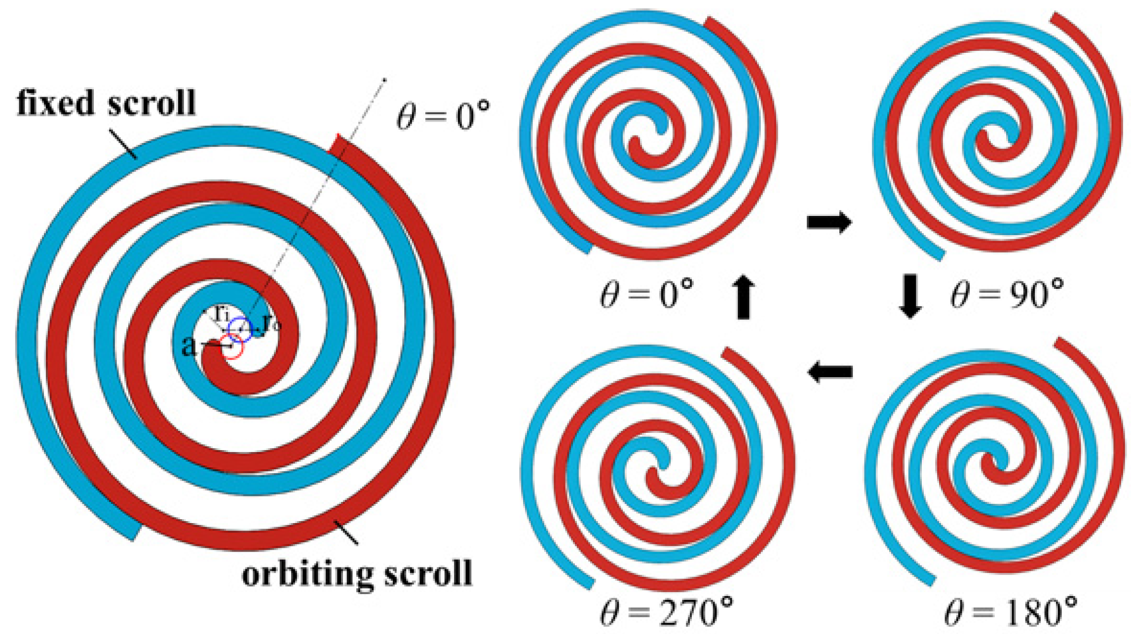
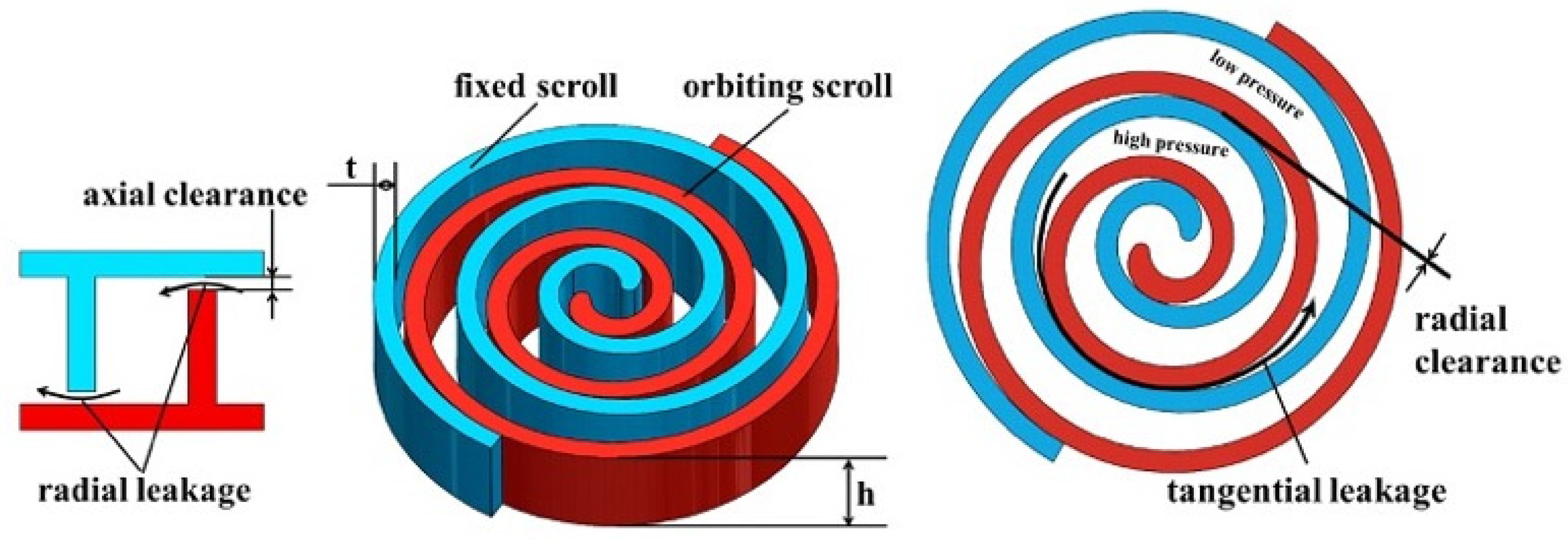
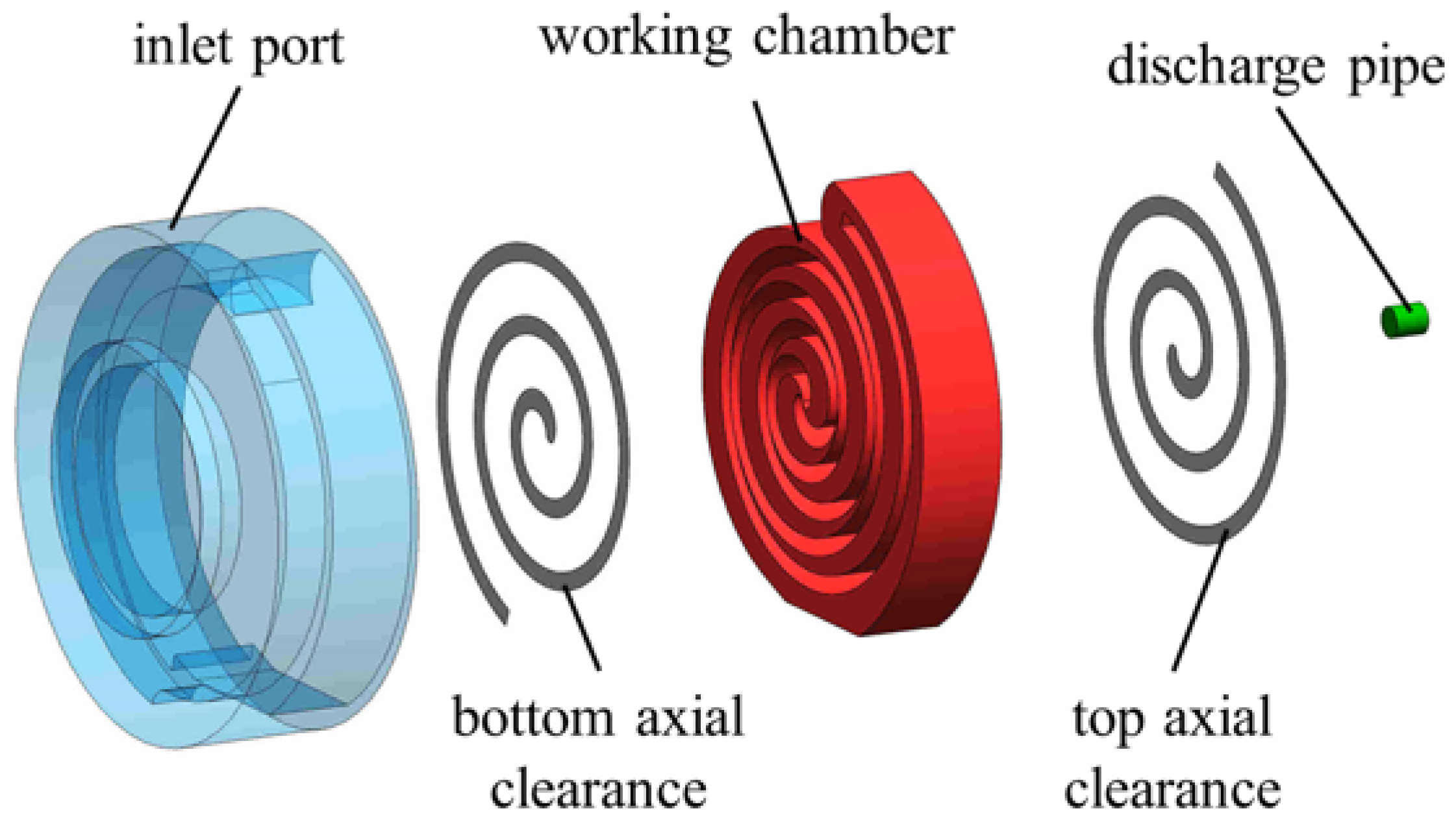
2.1. Geometric Model of Scroll Compressor

To improve the refrigeration capacity, a high-speed scroll compressor was designed in this study. The 3D model was obtained from the geometric characteristics of the actual high-speed refrigeration scroll compressor. The operating principle of a scroll compressor is also shown in Figure 1. The orbiting scroll rotates clockwise with the center point of the fixed scroll without rotating around its own axis and the orbiting radius is the eccentric distance. The scroll compressors contain crescent-shaped gas pockets whose volumes and sizes reduce gradually in the working process while the temperature and pressure inside the gas pockets increases. When the central chamber is connected to the discharge port and the pressure is higher than the backpressure, the gas will begin to discharge. The crank angle (θ) rotates from 0 to 360 degrees in one operation cycle of the compressor. When the crank angle is 0°, the suction process ends and the compression process begins.
The profiles of the scroll are the involute of a circle and the main parameters of the scroll are shown in Table 1, as illustrated in Figure 1 and Figure 2. The tip of the scroll profile was modified with the double arc. The radii of the two arcs were 5.586 mm and 1.588 mm, respectively. In practical engineering working progress, because of the limitation of machining accuracy, misalignment, and thermal expansion, the axial clearance and radial clearance cannot be avoided [27]. The leakage of working fluid in scroll compressors is a major reason for the decrease in compressor performance. It is necessary to study the scroll compressor model with axial clearance and radial clearance. In this study, the axial clearance and the radial clearance were both set as 10 μm. From Figure 2, it is obvious that radial leakage refers to the leakage occurring in the axial clearance, while tangential leakage refers to the leakage occurring in the radial clearance.

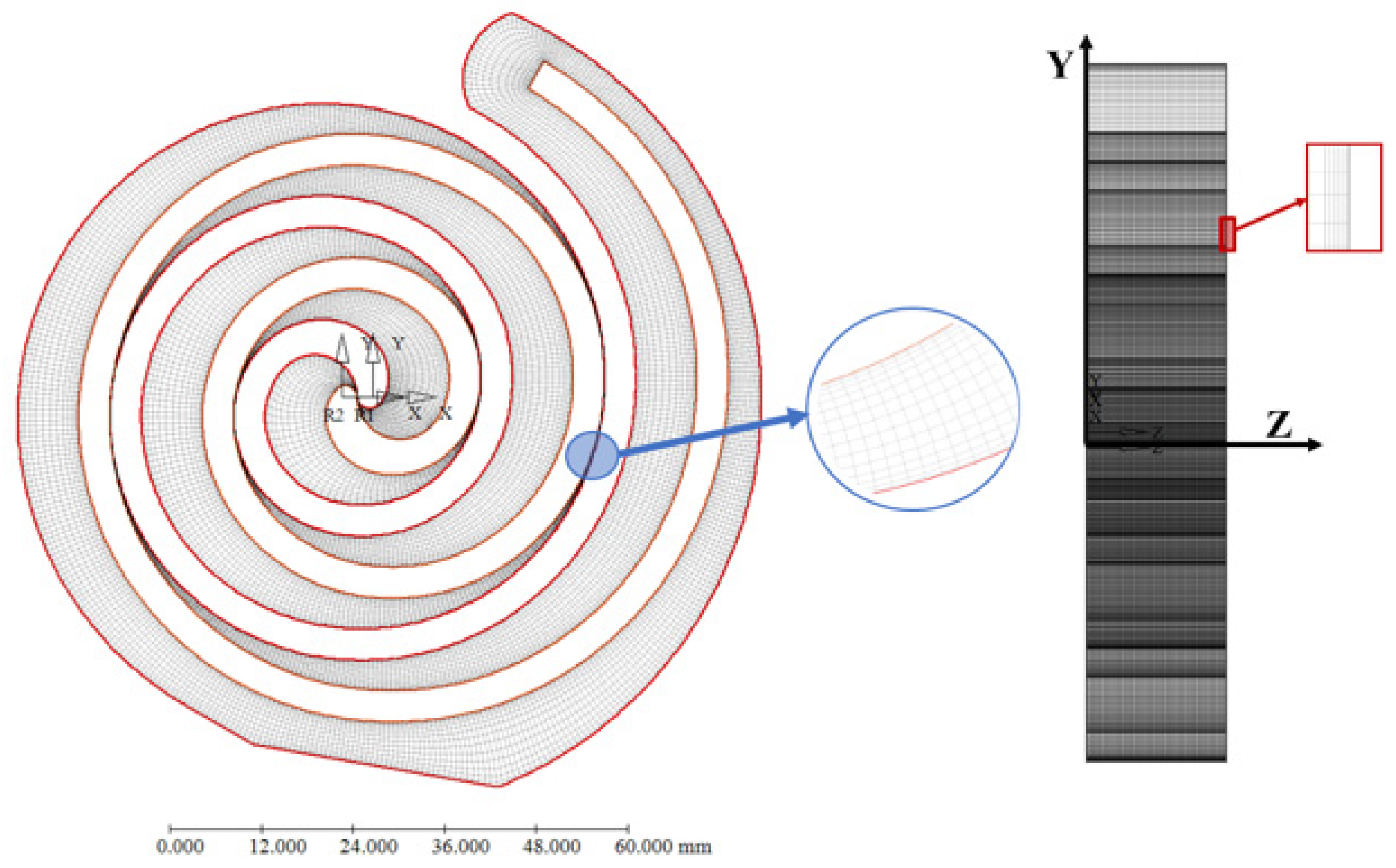
2.2. Mesh Generation

In Figure 3, the computational fluid domain is shown. In this paper, ANSYS-CFX is used to simulate the fluid domain from the suction port to the discharge port of a high-speed refrigeration scroll compressor. According to the physical model of the actual compressor, the whole simulation domain was divided into five subdomains including the inlet port, discharge pipe, top axial clearance, bottom axial clearance, and scroll working chamber, as displayed in Figure 3. This inlet port is a circumferential inlet encompassing the suction chamber. The bottom axial clearance is formed between the tip of the fixed scroll and the bottom plate of the orbiting scroll, while the top axial clearance is formed between the tip of the orbiting scroll and the bottom plate of the fixed scroll.
Due to the changes in gas pocket volume caused by the movement of the orbiting scroll as well as the complicated scroll profiles and small flank meshing clearances, it is essential to generate a dynamic mesh. The dynamic mesh should have enough high-quality grids in small meshing clearances to ensure simulation accuracy. Accordingly, the working chamber is the deforming domain, while the inlet port, discharge pipe, top axial clearance, and bottom axial clearance are the non-deforming domains. Hexahedral meshes are accepted to generate the deforming subdomain in TwinMesh, ensuring that there is enough grid density in radial leakage clearances between the fixed and orbiting scroll. The non-deforming subdomains were generated in ANSYS meshing, separately.
Figure 4 displays the structured mesh of the working chamber. CAD data of the working chamber were imported and used for the structured grid generation. The structured meshes were generated in the 2D plane, then multiple layers of the same 2D mesh in the Z-axis direction were generated. The final mesh must meet the quality requirements of orthogonality and aspect ratio. In gas pocket and radial clearances between the orbiting and fixed scroll, there were 15 layer grids to ensure the quality of the simulation, where the closer they were to the involute, the denser the grids. As shown in Figure 4, there were 50 layers in the Z-axis direction including five layers at both ends of the gap connection, and 40 layers in the middle of the working chamber. As for the non-deforming domain, there were also five layer grids in the two axial clearances. Different subdomains were connected by the interface.
In the scroll compressor, the orbiting scroll rotates around the center of the fixed scroll. With each rotation of one degree, their relative position changes, which results in the shape of the working domain changing. Therefore, a new mesh file is generated when the crank angle is increased by one degree. All of the mesh files meet the quality requirements under the same standard. In CFX, the junction box routine option [29] is used to load the grid file of the working chamber according to the time step.

2.3. Computational Model

Table 2 is the simulation model setting and operational conditions. In this numerical study, the actual gas, R134a, was used as a working fluid. The turbulence model was the shear stress transport model, which is widely used in rotary machinery fields. The adverse pressure gradients and strong streamline curvatures in radial clearances can be predicted by using the shear stress transport model [30]. The second-order backward Euler method was applied as the transient scheme, at the same time, the advection scheme was the high resolution.
The following equation describes the flow of refrigerant in the fluid domain [31],
d dt V ρ Φ dV + A ρ Φ UdA = A ( Γ Φ ) dA + V S d V Unsteady    Convection    Diffusion    Generation
After the simulation of the scroll compressor begins, the working chamber described in Figure 3 has the moving boundary. The dynamic mesh used in this domain will make the control volume change with time. The convection fluxes are calculated by using the relative velocity components of each cell face. Equation (1) must be modified. Therefore, the conservation equation will be as follows [32]:
d dt V ρ Φ dV + A ρ Φ ( U U i ) dA = A ( Γ Φ ) dA + V S d V Unsteady    Convection    Diffusion    Generation
where ρ is the fluid density; Φ is scalar transported in control volume (CV); V is the volume of CV; U is fluid velocity; Ui is the grid velocity which is independent on the rotation of the orbiting scroll. The motion of the orbiting scroll is defined by the user. In Equation (2), Γ is the diffusivity, A is the surface enclosing CV, and S is the source or sink in CV.
In this study, the rotational speed of the scroll compressor could reach 9000 rpm. There will be a substantial reduction in heat transfer under high-speed conditions [21]. Therefore, the wall surfaces of the scroll vane were set as the adiabatic and no-slip wall. The inlet temperature was 288.15 K, the inlet pressure was 349.96 KPa, and the outlet pressure was set to 1681.8 KPa. The calculation comes to an end when the residual converges to 10−4.

2.4. Grid Independence Check

The case at 3000 rpm in Table 2 was chosen to check the grid independence. Four groups of grids were adopted. The volumetric efficiency was defined as follows:
η = M a c t M t h e = M a c t V i n n / v i n
where Vin is the volume of the inlet chamber; n is rotational speed; vin is inlet specific volume; Mact is the actual mass flow. When calculating the volumetric efficiency of the simulation, the Mact can be obtained statistically from the simulation results.
Table 3 displays how the volumetric efficiency was modified with the mesh elements. The simulation results of four cases of different number of grids were compared. The layers in the XY-plane and Z-axis direction were used to describe the deforming subdomain, which was generated in the working chamber. The layers in the XY-plane were the layers of grids in the gas pocket and radial clearances between the orbiting and fixed scroll. The layers in the Z-axis direction refer to the generated layers of the same 2D mesh in the Z-axis direction. As for the number of grids of all domains, it consisted of the deforming and non-deforming subdomains, which were all of the meshes generated for this compressor. In case 3, the volumetric efficiency changed under 1% when the grid number was 2,010,369, and it was considered that the grid quality met the calculation requirements. Therefore, case 3 with 2,010,369 mesh elements and 15 layers in the radial clearance is applied to calculate all of the cases in Table 2.

3. Results and Discussion

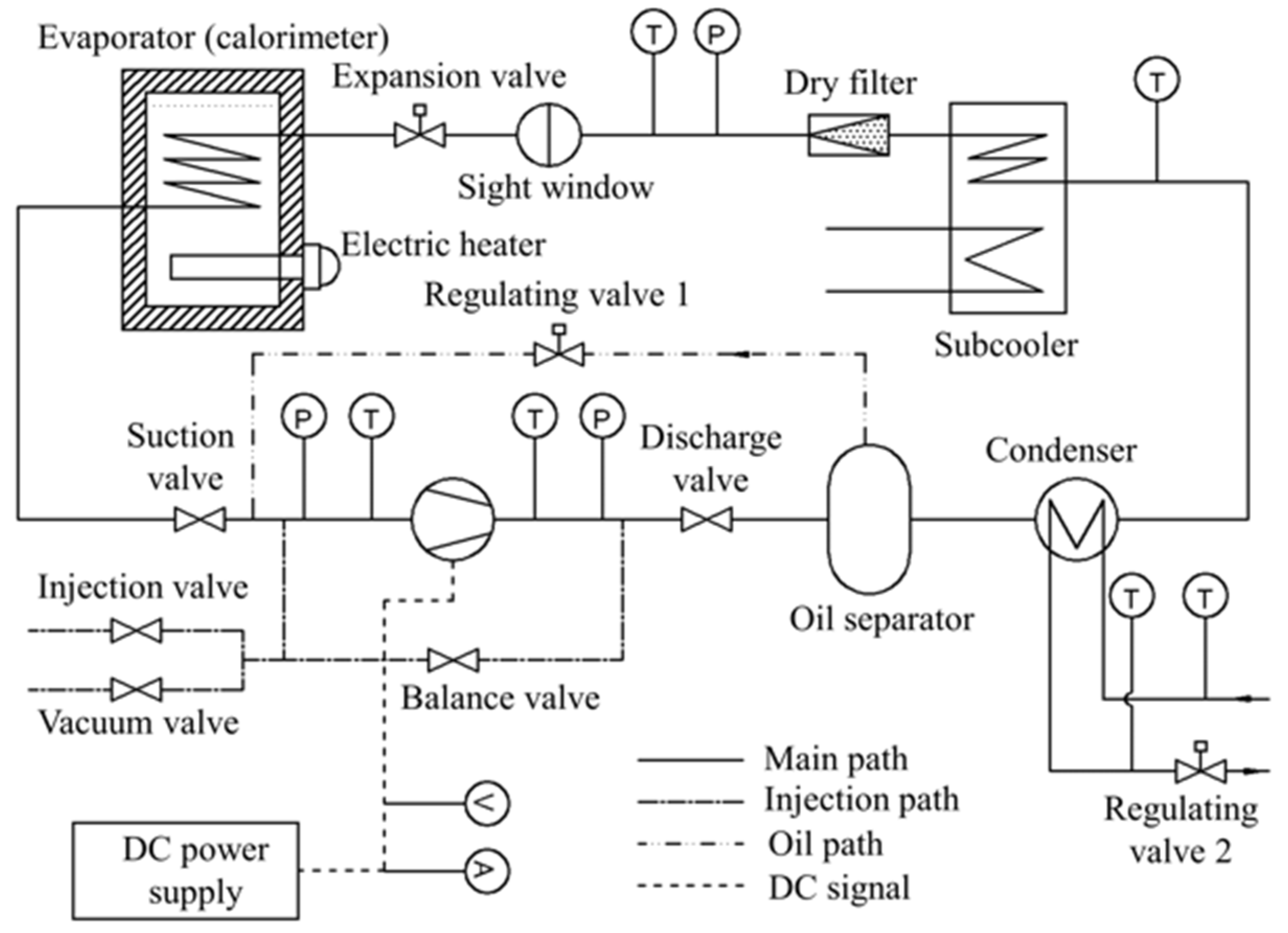
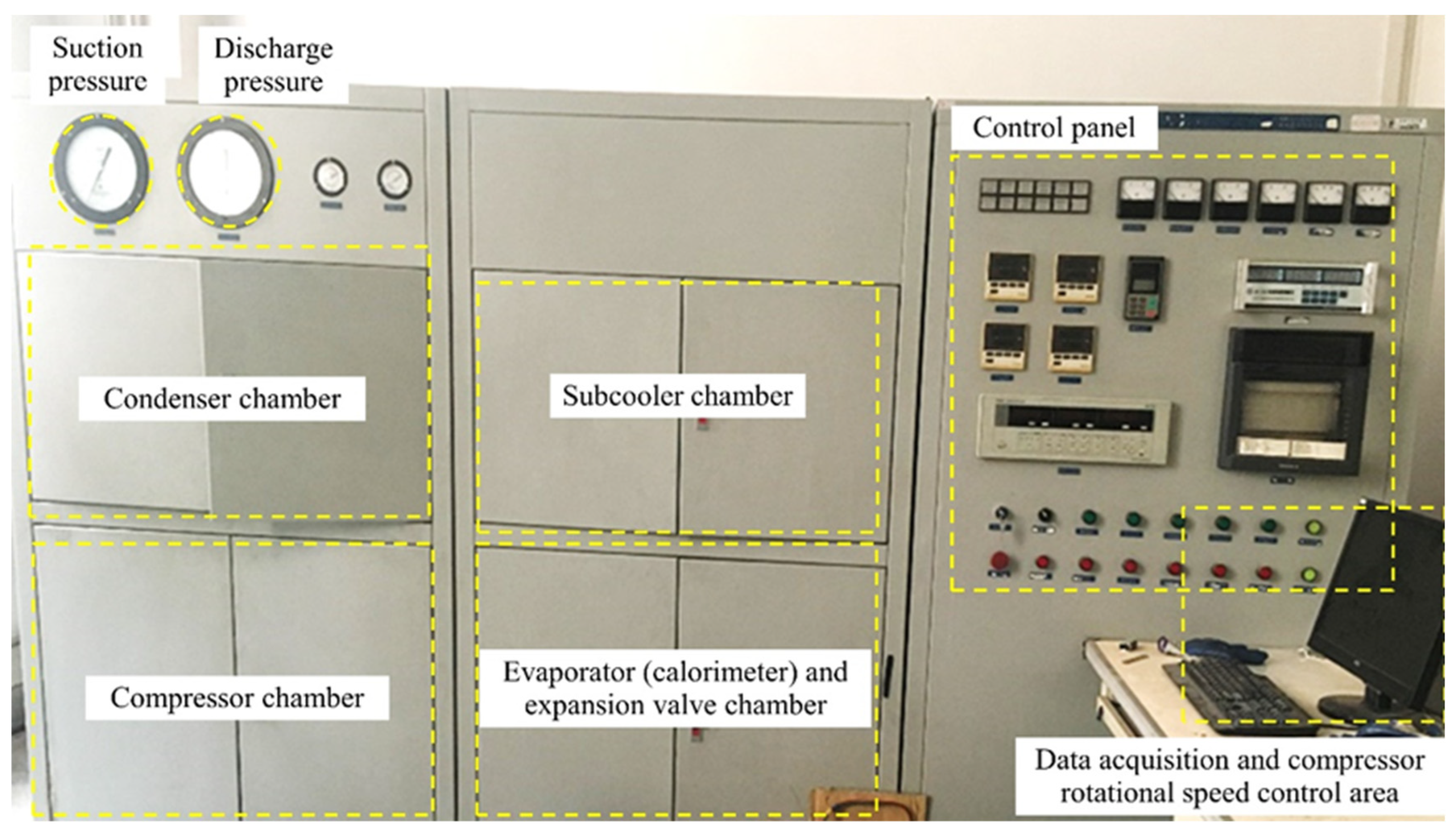
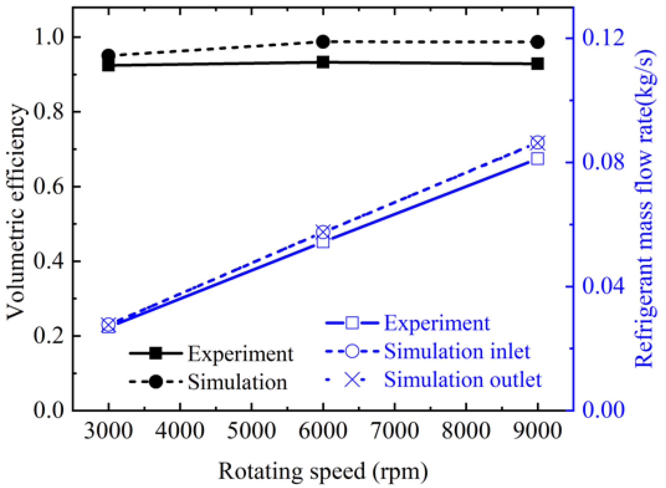
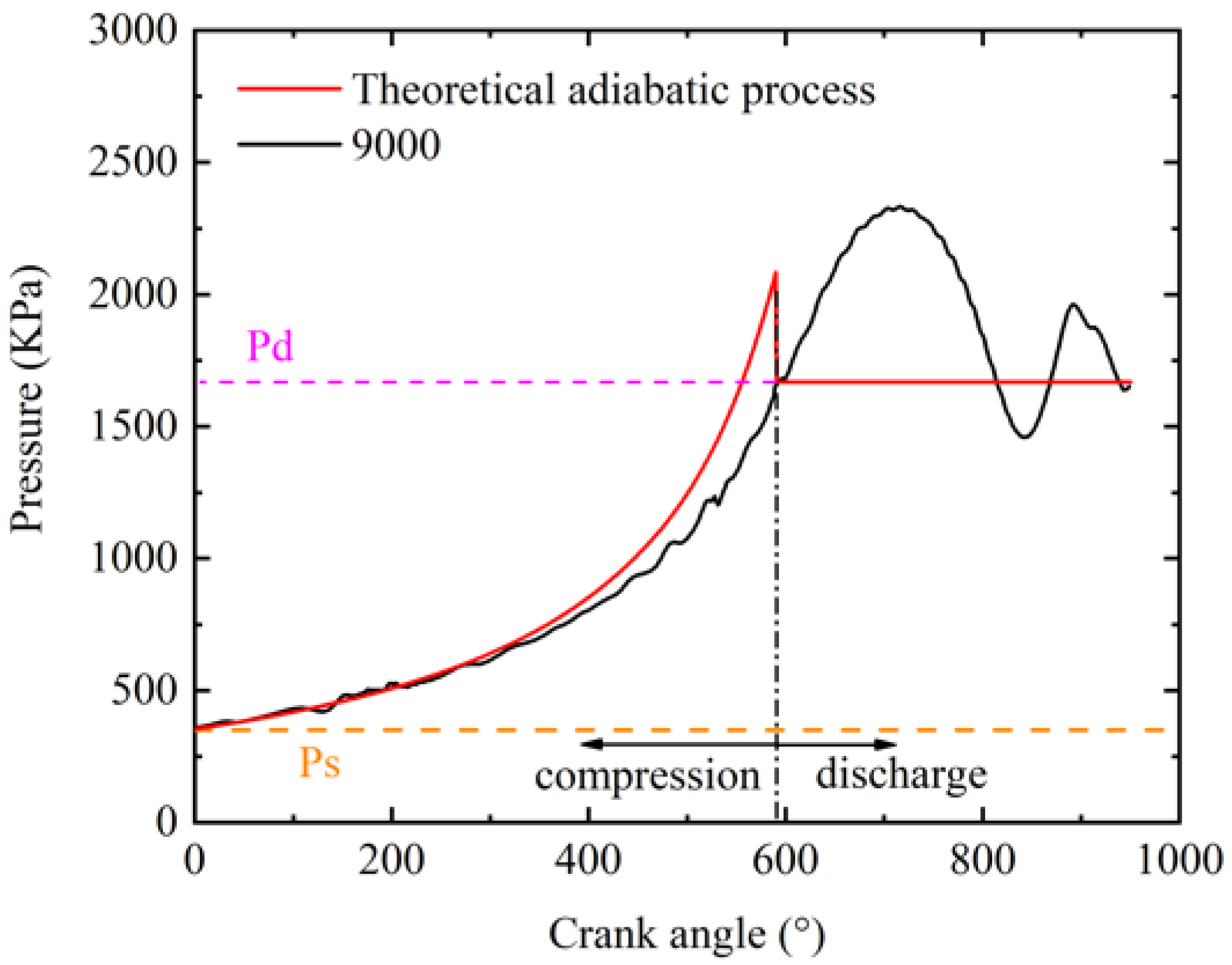
3.1. Experimental Validation

To validate the simulation results, experiments were carried out on a real high-speed refrigeration scroll compressor whose geometric parameters were used in this paper. The schematic diagram of the calorimetric test system is shown in Figure 5. The test system was mainly composed of the main path, injection path, oil path, and direct current (DC) signal path. A high-speed refrigeration scroll compressor, a condenser, a subcooler, an expansion valve, and an evaporator (calorimeter) were included in the main path. Not only could the suction pressure, suction temperature, discharge pressure, and discharge temperature of the compressor be adjusted through the control panel, but also the superheat and subcooling. The condenser was a double-tube heat exchanger, which requires cooling water in the thermostat to take away heat.
The calorimeter was a sealed pressure chamber. The evaporator of the refrigeration system was installed on the top of the chamber, and the electric heater was installed at the bottom. The electric heater was soaked by the second kind of refrigerant (R114), which was different to the working fluid. After connecting the measured compressor to the test system, the parameters of the test system can be adjusted to the working condition, so the evaporator above the inside of the calorimeter will be cooled, and the electric heater at the bottom will be heated. When the refrigerating capacity is greater than the electric heating capacity, the pressure of R114 in the calorimeter will continue to drop. In contrast, if the refrigerating capacity is less than the electric heating capacity, the pressure of R114 will rise. Finally, there is a balance between them. At this time, the electric heating power of the electric heater is measured, which would be equal to the cooling capacity of the compressor under this working condition.
Figure 6 shows the device layout for the compressor test system. Before the test, the system should be filled with nitrogen to 2 MPa. In order to ensure no leakage, the system pressure should remain unchanged for 24 h. During the test, the system should establish a stable state. The measurement data are collected every 15 min after the test condition is stable for half an hour. In this experiment, PT100 was used as the temperature sensor. The pressure sensor adopted was a piezoresistive pressure sensor. The accuracy of each sensor is shown in Table 4. In addition, the suction temperature and pressure, discharge temperature and pressure, mass flow rate of R134a, and input power of the scroll refrigeration compressor were tested and calculated under variable rotational speed operating conditions. For the experiments, it was necessary to calculate the actual mass flow rate (Mact) of R134a in order to obtain volumetric efficiency. Mact was calculated as shown in Equation (4).
M a c t = P h e a t H o u t H i n
where Pheat is the heating power of the electric heater; Hin and Hout are the inlet and outlet enthalpy of the calorimeter, respectively.
Figure 7 indicates that the volumetric efficiency had the same variation tendency in the simulation and experiments. With the rotational speed increasing from 3000 rpm to 6000 rpm, the volumetric efficiency improved both in the simulation and experiments, but there was a slight reduction with the rotational speed increasing from 6000 rpm to 9000 rpm. The maximum volumetric efficiency deviation between the simulated and experimental results was 6.3% at 9000 rpm. In the experiments, due to assembly, fabrication, deformation, and other problems, the compressor clearance increased, leading to more leakage. The leakage resulted in the simulated volumetric efficiency being a little higher than that of the test. The simulated inlet and outlet mass flow were very close to the experimental measurements, while the pressure boundary conditions were used in the simulation inlet and outlet. The maximum deviation was 6.4% and 6.3% at 9000 rpm, respectively, so can be considered as excellent and reliable.

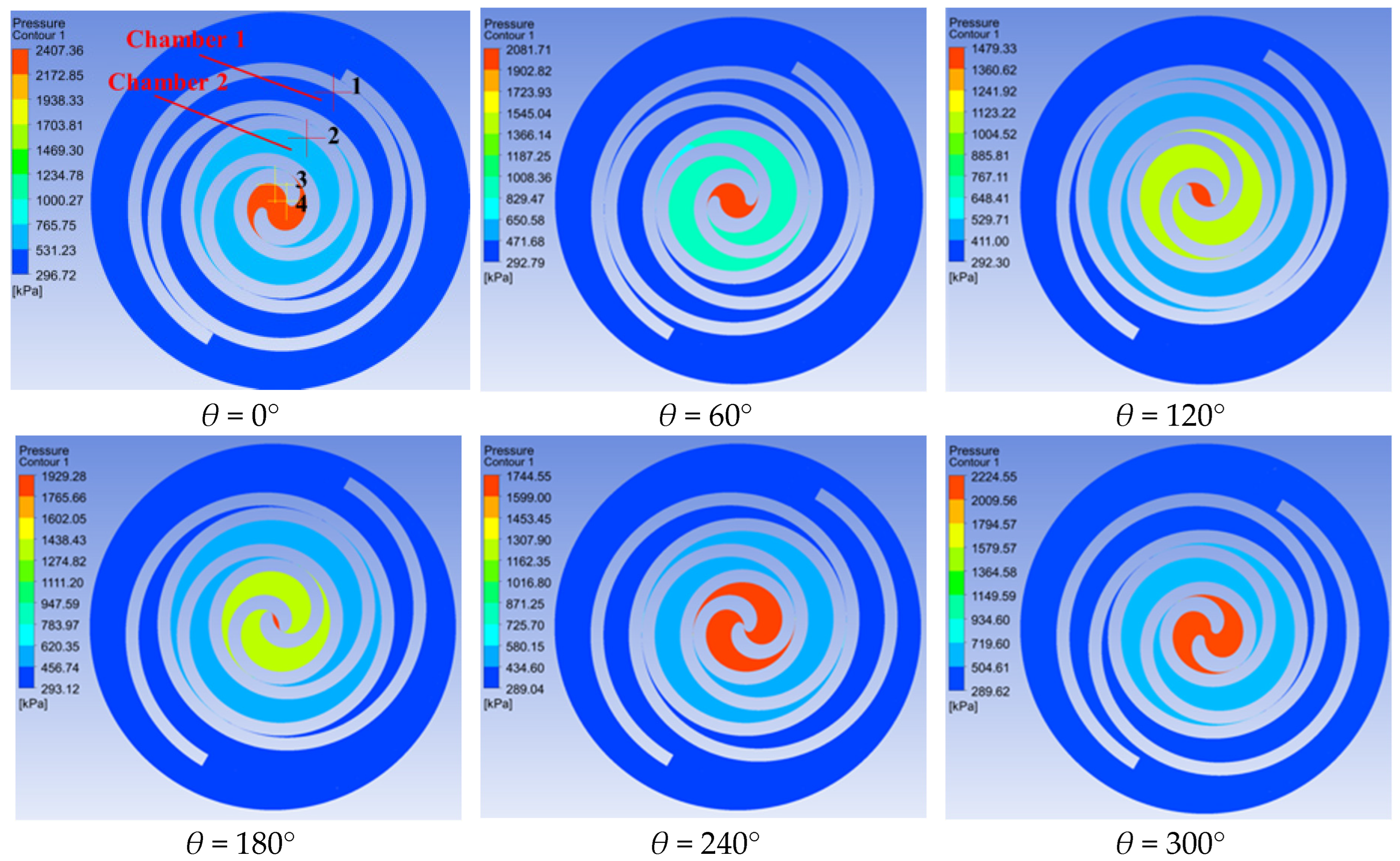
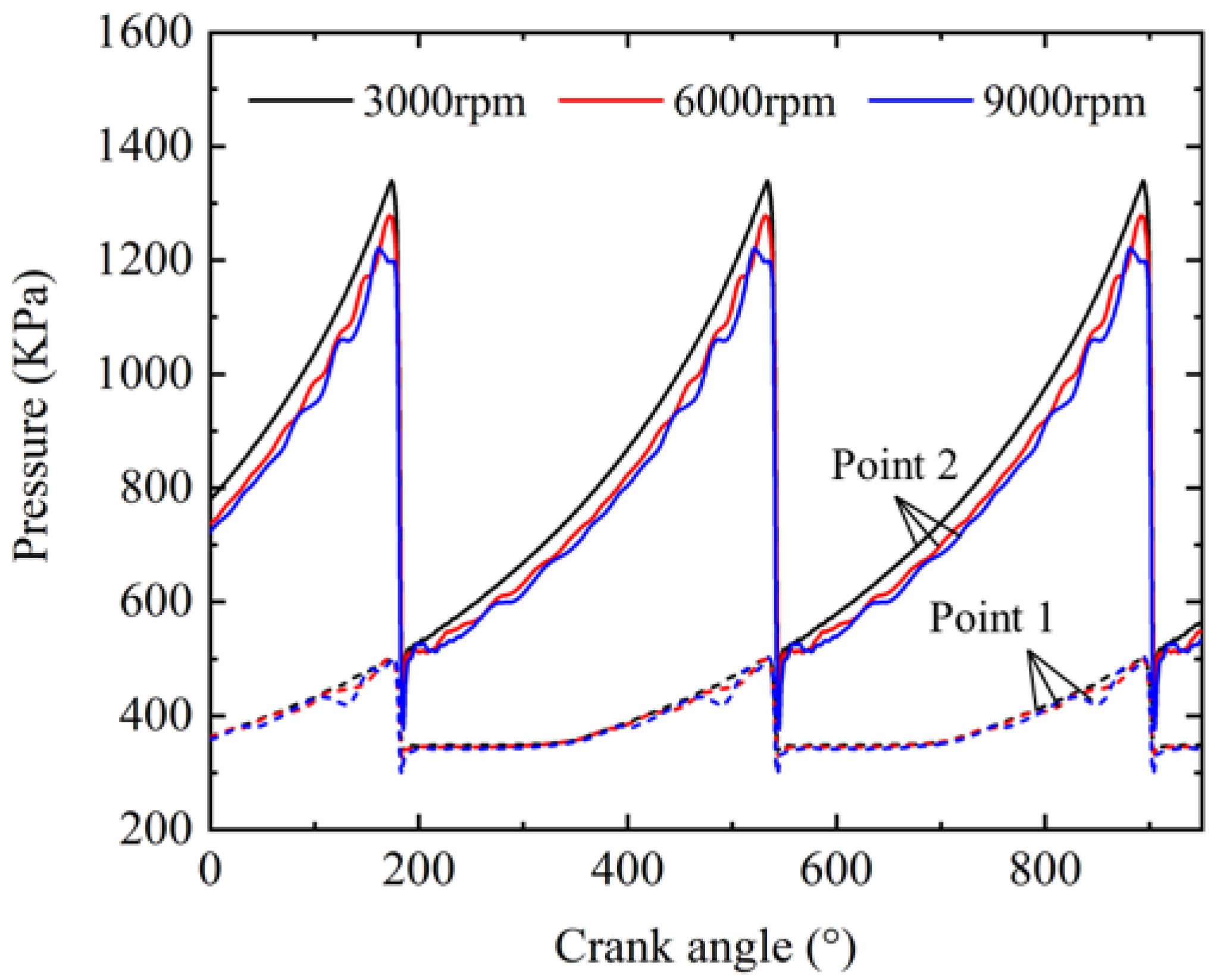
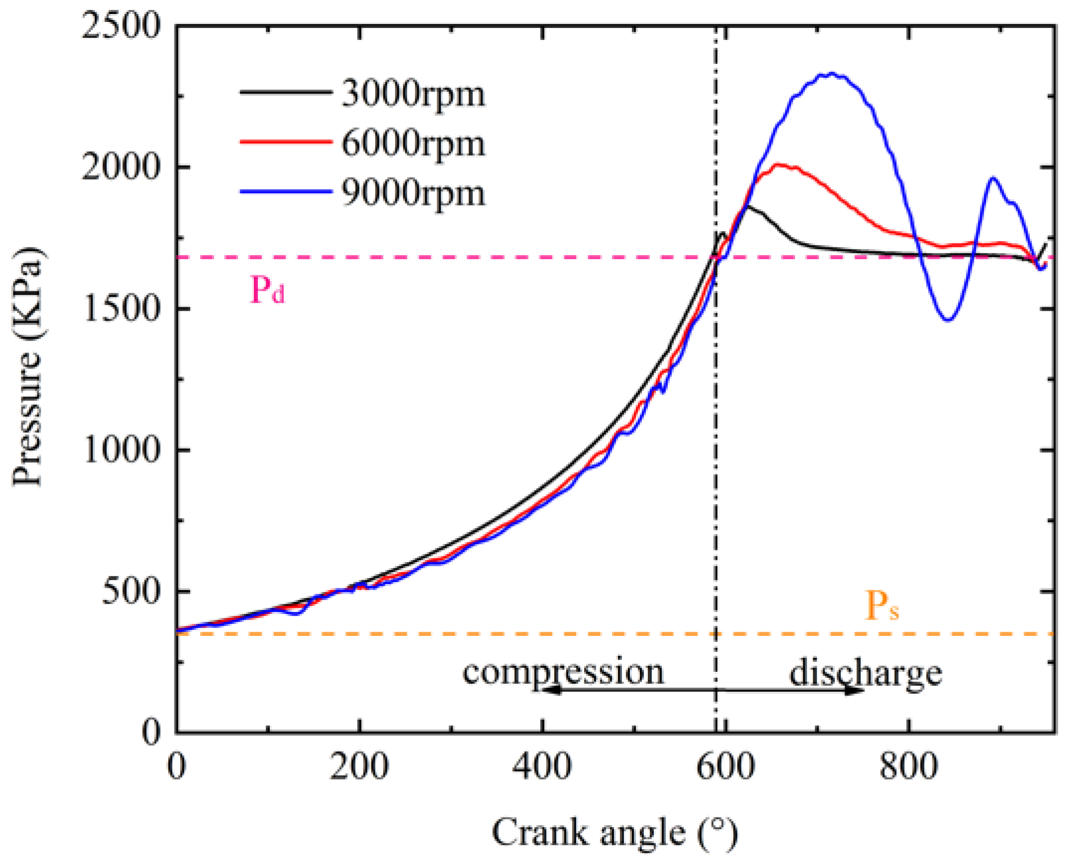
3.2. Effect of High Speed on the Pressure Field

Figure 8 shows the pressure distribution of 9000 rpm, in which the crank angle increased from 0° to 360°. The circumferential intake structure was adopted in this simulation calculation, and the discharge pipe was virtually symmetrical. Notably, the pressure fields were nearly symmetrical, and there was no time delay in the pressure change process. Accordingly, the pressure in the different gas pockets was approximately the same. Monitor points were set at points 1, 2, 3, and 4 in Figure 8. The pressures in chamber 1, chamber 2, and the discharge chamber were obtained by using points 1, 2, 3, and 4. The pressure of the discharge chamber was represented by points 3 and 4.
A theoretical adiabatic model was calculated to validate the results of the 3D transient simulation in which the pressure in the compressor chamber can be calculated by Equation (5).
P θ = P s ( V s V θ ) n
We assumed that the pressure in the same compressor chamber was the same and did not consider the effects of leakage, where Pθ is the pressure in the compressor chamber when the crank angle is θ, Ps is the suction pressor, vs. is the volume of suction chamber, Vθ is the volume of the compressor chamber when the crank angle is θ, and n is the adiabatic index, which was 1.2 in this equation, and 1.2 was the arithmetic average of the adiabatic index at the inlet and outlet of the compressor.
Figure 9 presents the comparison of the pressure change profiles with the crank angle between the theoretical adiabatic process and 3D transient simulation. Before reaching the exhaust angle (θ = 588.9°), there is a compression process. The pressure value of the 3D transient simulation was close to the theoretical adiabatic process in the first half of the compression process, indicating that the internal leakage was small. However, in the second half of the compression process, as the pressure in the compression chamber increased, the internal leakage increased, resulting in a deviation between the simulated results and the theoretical pressure curve of the adiabatic process. Therefore, the theoretical model cannot reflect the over-compression and pressure fluctuations.
The pressure lines at monitor points 1 and 2 in the working chamber are shown in Figure 10. Before the meshing point between the orbiting and fixed scroll reached the monitoring point, the pressure at the monitoring point increased gradually and reached the maximum value when the meshing point overlapped it. After the meshing point passed, this point was connected with the next working chamber, and the pressure suddenly decreased. As shown in Figure 10, the pressure fluctuated at the working chamber, and the higher the rotational speed, the greater the pressure fluctuation. The pressure fluctuation in the compression process was mainly caused by the solid boundary motion. Hence, the higher the speed, the greater the pressure fluctuation.
In Figure 11, the change in the chamber pressure with the crank angle is displayed. There was obvious over-compression at the discharge process at different rotational speeds, which increased with the increase in the rotational speed. Therefore, when the compressor is running at high speed, the discharge valve could be opened appropriately in advance. Furthermore, a huge pressure fluctuation occurred in the discharge chamber at 9000 rpm, which will lead to larger discharge pressure pulsation. The compression process index decreased with the increase in the rotational speed, indicating that the heat transfer of the working gas decreases with the increase in rotational speed. To sum up, more severe pressure fluctuations, larger over-compression, and lower heat transfer of the working gas would occur in the discharge chamber under high-speed operating conditions.

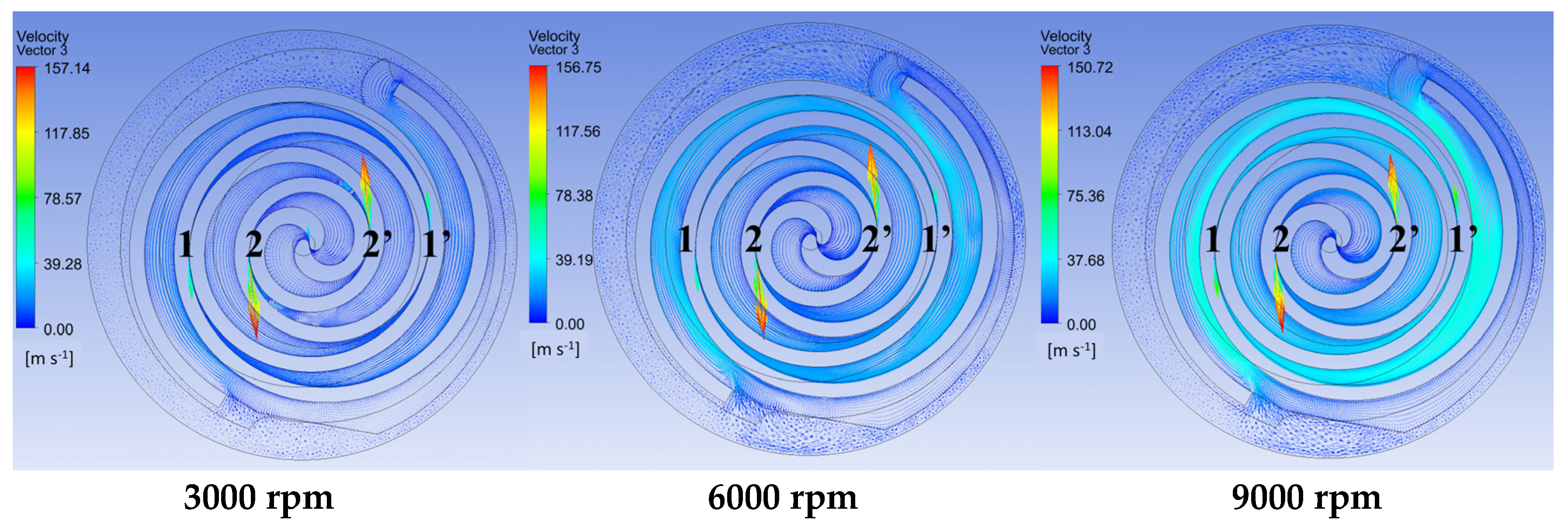
3.3. Effect of High Speed on Tangential Leakage

Figure 12 shows the velocity distributions in the cross-sections of the working chambers at 3000 rpm, 6000 rpm, and 9000 rpm. The crank angle in this figure was 240°. The flow of refrigeration in the gas pockets was laminar and the velocity was small. Due to the influence of orbiting scroll movement, a greater rotational speed means that there is a greater gas flow velocity in the gas pocket. In radial clearance, there were high-velocity tangential leakages from the high-pressure chambers to the low-pressure chambers. Two pairs of symmetrical compression chambers resulted in two pairs of symmetrical tangential leakages (1, 1′, 2, 2′) and the radial clearance of 2 and 2′ were closer to the discharge chamber than 1 and 1’; 2 and 2′ had a larger pressure difference between the high-pressure and low-pressure chambers. Therefore, the maximum tangential leakage occurred at 2′ and 2′ under the same crank angle and rotational speed.
Variations in the maximum tangential leakage velocity and the flow velocity of 2 and 2′ with the crank angle is indicated in Figure 13. It can be seen from Figure 13 that the flow velocity of 2 and 2′ was sinusoidal with the crank angle, and with the increase in the rotational speed, the crank angle of the maximum flow velocity of 2 and 2′ was larger.
According to the above analysis, at different rotational speeds, the crank angle where the maximum tangential leakage occurs is shown in Figure 13. The maximum tangential leakage velocity was 159.75 m/s at 3000 rpm, 162.85 m/s at 6000 m/s, and 164.33 m/s at 9000 rpm. As can be seen from the figure, the position where the maximum tangential leakage occurred was closer to the starting part of the scroll with an increase in the rotational speed. Therefore, the radial seal and the matching of the scroll side wall are very important at the beginning of the scroll in high-speed scroll compressors.

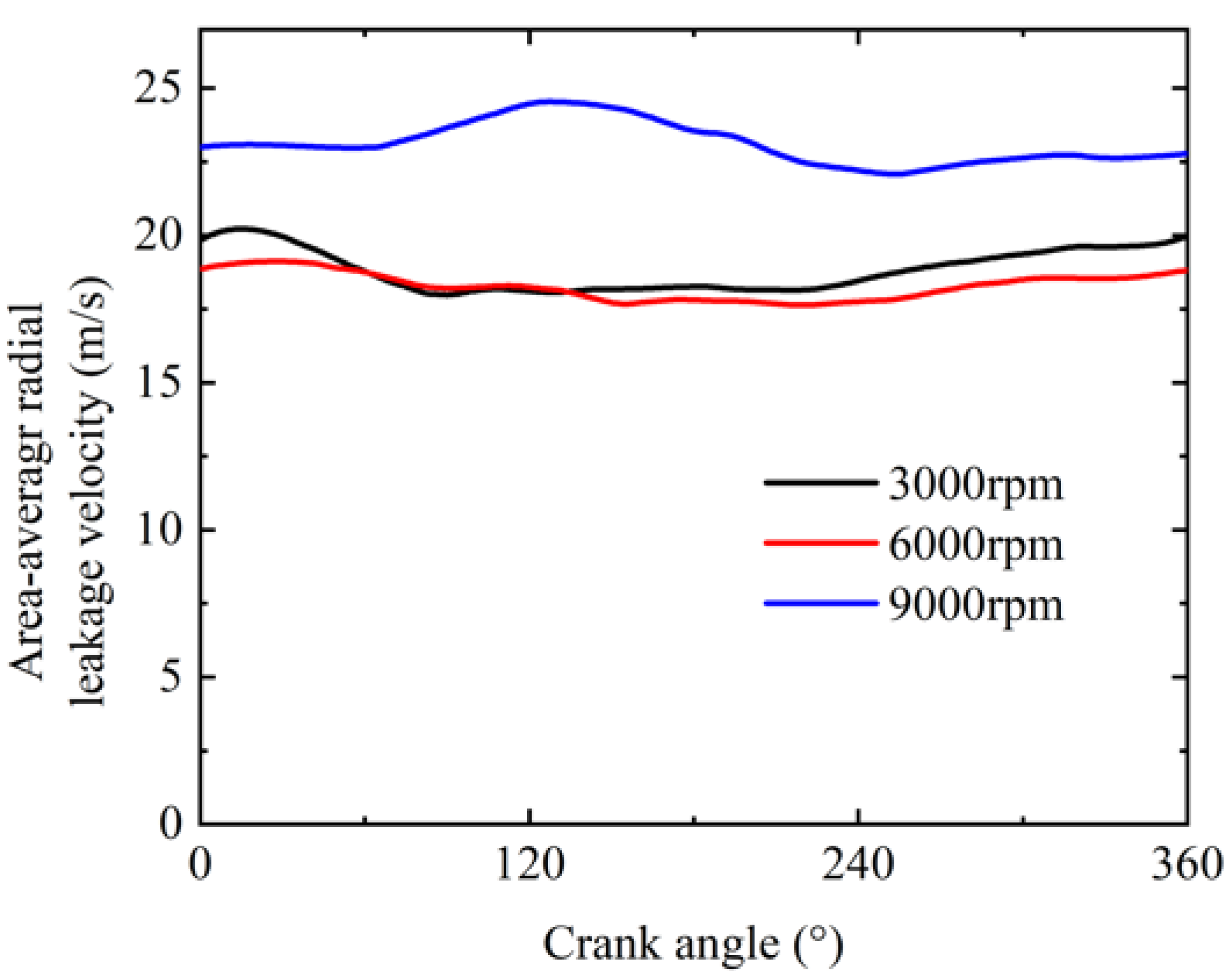
3.4. Effect of High Speed on Radial Leakage

Figure 14 and Figure 15 display the velocity distributions in the cross-sections of the bottom and top axial clearance at 3000 rpm, 6000 rpm, and 9000 rpm. The rotational angle of this figure was 240°, and in the figures, the black dotted lines are the meshing line between the orbiting and the fixed scroll. This figure also includes the pressure contours of the chamber. The radial leakage was mainly observed in the axial clearance between the inner and outer chambers because of the pressure difference. However, there was also a slight leakage between a pair of symmetrical chambers. This was caused by the motion of the orbiting scroll, where gas flows into the axial clearance from the symmetrical chambers on both sides and leaks along the direction of the scroll rolling. Regarding the leakage between the asymmetric working chambers, A and A’ can be regarded as the starting point of the leakage, and B and B’ can be regarded as the ending point of leakage. It always reached the maximum leakage at A. Because there was also an axial leakage effect in addition to radial leakage at the starting point, the pressure difference between two chambers of point A was greater than that of point A’. At points B and B’, the gas in the low-pressure chamber flowed into the high-pressure chamber. This was caused by the pressure reduction in the axial clearance, which resulted from the high-speed flow of tangential leakage.
Figure 16 displays the variations in the maximum radial leakage velocity with the crank angle at 3000 rpm, 6000 rpm, and 9000 rpm, that is, the flow velocity at point A. It can be seen that the velocity at point A showed a sinusoidal trend with the increase in the rotational angle, and the amplitude increased slightly with the increase in the rotational speed. The maximum radial leakage velocity was 145.77 m/s at 3000 rpm, 147.99 m/s at 6000 m/s, and 150.50 m/s at 9000 rpm. The crank angle of the peak was different, which showed a progression with the increase in the rotation speed. Accordingly, the position where the maximum radial leakage occurred was closer to the starting part of the scroll tip with the increase in the rotational speed. Hence, the axial seal at the starting part of the scroll is very important in high-speed scroll compressors.
Figure 17 shows the area-average radial leakage velocity on the flank of the bottom axial clearance domain. However, the area-average velocity had approximately the same size at 3000 rpm and 6000 rpm, the latter even slightly smaller than the former. However, the area-average radial leakage velocity under the high-speed condition of 9000 rpm was much higher than that at 3000 rpm and 6000 rpm. The relationship between leakage and speed is not a simple positive correlation, so it is extremely necessary to study the leakage characteristics under different operating conditions, especially under high-speed conditions.

4. Conclusions

In this paper, a 3D transient simulation model with dynamic meshing that considered the axial and radial clearance of a high-speed scroll refrigeration compressor was established. The radial and the axial clearances were both set at 0.01 mm, which is consistent with the actual size. A sufficient number of high-quality hexahedral meshes were generated in the working chamber domain to solve the problem of the insufficient number of mesh layers in the radial clearance. The real gas R134a was used as the working fluid, and the simulation was carried out under three working conditions of 3000 rpm, 6000 rpm, and 9000 rpm. When the rotational speed was set as 3000 rpm, 6000 rpm and 9000 rpm alternatively, the difference in the volume efficiency between the simulation results and the experimental results was below 6.3%.The influence of high rotation speed on the pressure field, tangential leakage, and radial leakage was studied. Some conclusions are presented as follows.
  • At high-speed conditions, there were greater pressure fluctuations in compression chambers due to the faster solid boundary motion at higher speeds. Additionally, the compression process index decreased with the increase in the rotational speed, indicating that the heat transfer of the working gas decreases. In the discharge process, there are much larger pressure fluctuations and over-compression. Therefore, when the compressor is running at a high rotational speed, the discharge valve could be opened appropriately in advance.
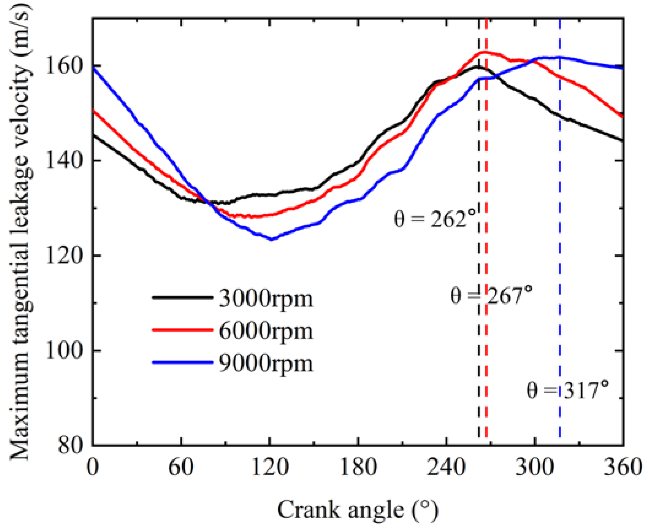
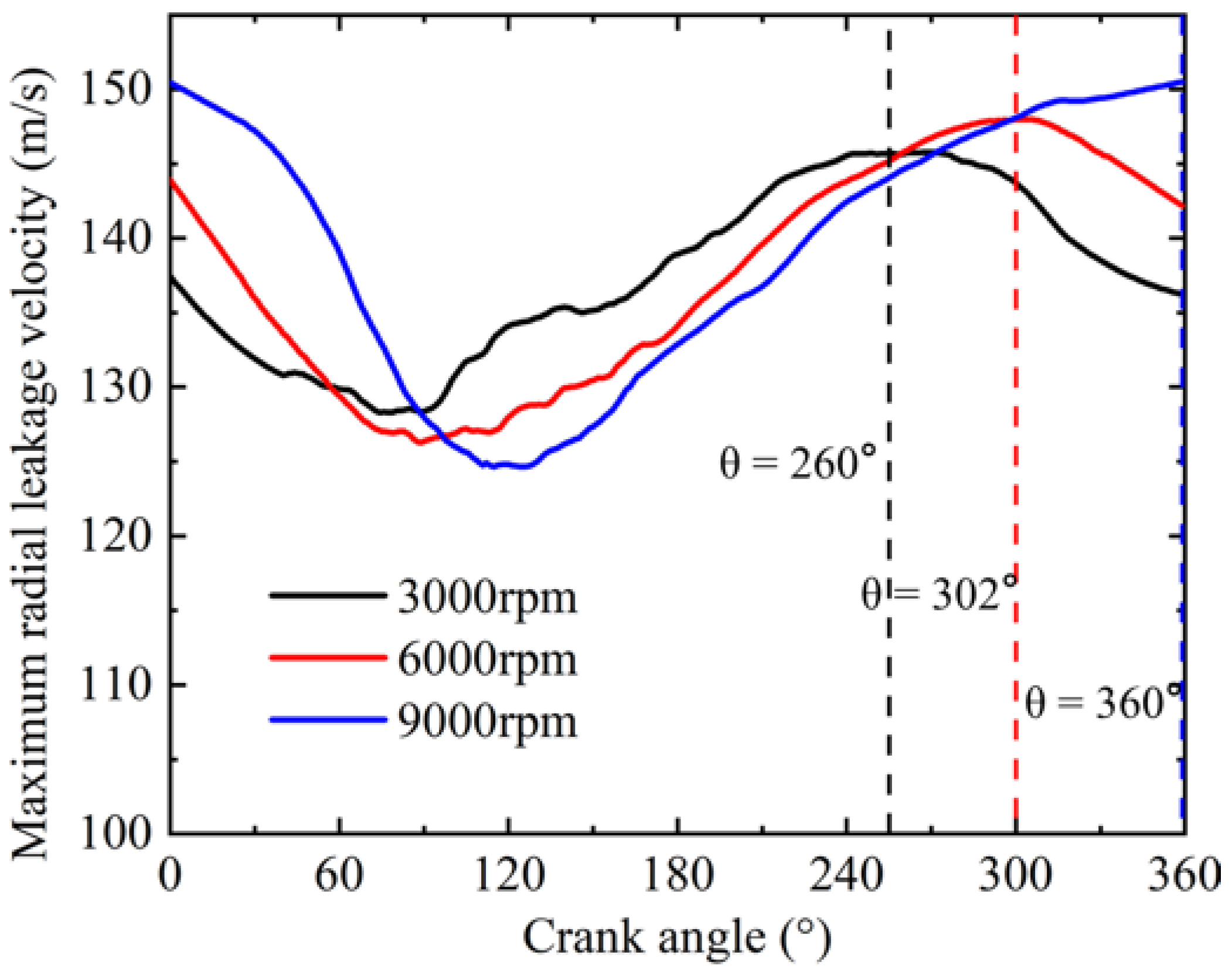
  • The maximum axial leakage velocity was larger than the maximum radial leakage velocity. The maximum tangential leakage velocity was 159.75 m/s at 3000 rpm, 162.85 m/s at 6000 m/s, and 164.33 m/s at 9000 rpm. The maximum radial leakage velocity was 145.77 m/s at 3000 rpm, 147.99 m/s at 6000 m/s, and 150.50 m/s at 9000 rpm.
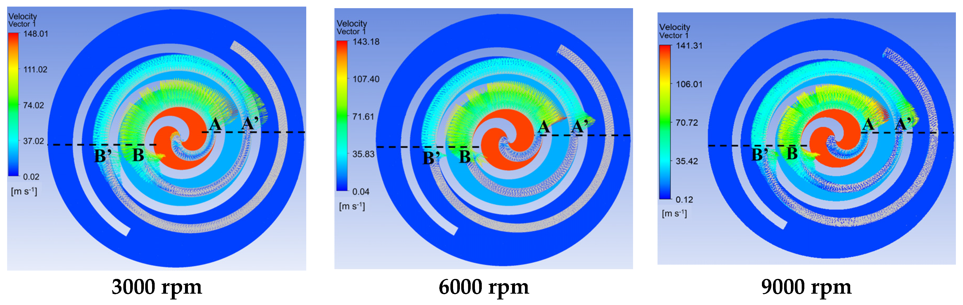
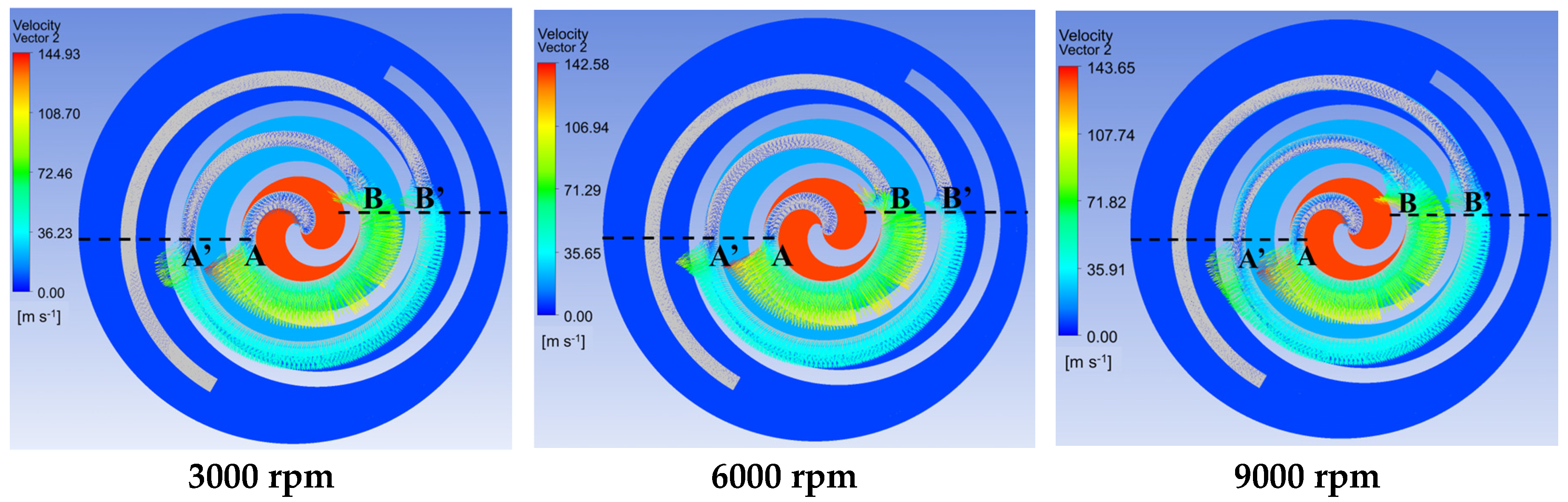
  • The axial clearances were where the radial leakage was mainly observed. However, there was also a slight leakage between a pair of symmetrical chambers, where gas flowed into the axial clearance from the symmetrical chambers on both sides and leaked along the direction of the scroll rolling. At the ending point of radial clearance, the gas in the low-pressure chamber flowed into the high-pressure chamber.
  • The maximum tangential and radial leakage velocity showed a sinusoidal trend with the increase in the crank angle. With the increase in the rotational speed, the crank angle of the maximum tangential and radial leakage increased and the position was closer to the starting part of the scroll. Hence, the axial and radial seal at the starting part of the scroll is very important in high-speed scroll compressors.
  • The relationship between radial leakage and speed is not a simple proportional relation, so it is extremely necessary to study the leakage characteristics under different operating conditions, especially under high-speed conditions.

Author Contributions

Conceptualization, X.L., W.W. and F.K.; methodology, X.L. and W.W.; software, X.L., J.Z., C.G. and F.J.; validation, J.Z., and C.G.; formal analysis, X.L., J.Z., C.G. and F.J.; investigation, X.L., W.W., J.Z., C.G., F.K. and F.J.; resources, W.W., F.K. and F.J.; data curation, J.Z., and C.G.; writing—original draft preparation, X.L. and J.Z.; writing—review and editing, X.L., W.W., J.Z., C.G., F.K. and F.J.; visualization, X.L., J.Z. and C.G.; supervision, X.L., W.W., F.K. and F.J.; project administration, X.L., W.W. and F.K.; funding acquisition, W.W. All authors have read and agreed to the published version of the manuscript.

Funding

This work was supported by NIO University Programmer (NIO UP). The APC was also funded by NIO University Programmer (NIO UP).

Data Availability Statement

The data presented in this study are available on request from the corresponding author. The data are not publicly available due to confidentiality requirements of the project.

Conflicts of Interest

The authors declare no conflict of interest.

References

  1. Wagner, J.; Markham, D. Design of a Compact, Lightweight Screw-type Compressor for Refrigeration Systems. In Proceedings of the 2016 15th IEEE Intersociety Conference on Thermal and Thermomechanical Phenomena in Electronic Systems (ITHERM), Intersociety Conference on Thermal and Thermomechanical Phenomena in Electronic Systems, Las Vegas, NV, USA, 31 May–3 June 2016; pp. 1494–1500. [Google Scholar]
  2. Hareland, M.; Hoel, A.; Jonsson, S.; Liang, D. Selection of Flapper Valve Steel for High Efficient Compressor. In Proceedings of the International Compressor Engineering Conference, West Lafayette, IN, USA, 14–17 July 2014; pp. 1–9. [Google Scholar]
  3. Kang, S.-M.; Yang, E.; Shin, J.-U.; Park, J.-H.; Lee, S.-D.; Ha, J.-H.; Son, Y.-B.; Lee, B.-C. Development of High Speed Inverter Rotary Compressor for the Air-conditioning System. In Proceedings of the 9th International Conference on Compressors and Their Systems, IOP Conference Series-Materials Science and Engineering, London, UK, 7–9 September 2015; IOP Publishing Ltd.: Bristol, UK, 2015. [Google Scholar]
  4. Tian, Z.; Gu, B. Analyses of an integrated thermal management system for electric vehicles. Int. J. Energy Res. 2019, 43, 5788–5802. [Google Scholar] [CrossRef]
  5. Choi, Y.U.; Kim, M.S.; Kim, G.T.; Kim, M.; Kim, M.S. Analyse de la performance d’un système de pompe à chaleur à injection de vapeur pour les véhicules électriques devant démarrer sous températures froides. Int. J. Refrig. 2017, 80, 24–36. [Google Scholar] [CrossRef]
  6. Schein, C.; Radermacher, R. Scroll compressor simulation model. J. Eng. Gas Turbines Power 2001, 123, 217–225. [Google Scholar] [CrossRef]
  7. Chen Yu Halm, N.P.; Groll, E.A.; Braun, J.E. Mathematical modeling of scroll compressors—Part I: Compression process modeling. Int. J. Refrig. 2002, 25, 731–750. [Google Scholar] [CrossRef]
  8. Chen, Y.; Halm, N.P.; Braun, J.E.; Groll, E.A. Mathematical modeling of scroll compressors—part II: Overall scroll compressor modeling. Int. J. Refrig. Int. Froid 2002, 25, 751–764. [Google Scholar] [CrossRef]
  9. Blunier, B.; Cirrincione, G.; Herve, Y.; Miraoui, A. A new analytical and dynamical model of a scroll compressor with experimental validation. Int. J. Refrig. Int. Froid 2009, 32, 874–891. [Google Scholar] [CrossRef]
  10. Wang, B.; Shi, W.; Li, X. Numerical analysis on the effects of refrigerant injection on the scroll compressor. Appl. Therm. Eng. 2009, 29, 37–46. [Google Scholar] [CrossRef]
  11. Wang, B.; Shi, W.; Li, X.; Yan, Q. Numerical research on the scroll compressor with refrigeration injection. Appl. Therm. Eng. 2008, 28, 440–449. [Google Scholar] [CrossRef]
  12. Stosic, N.; Smith, I.K.; Zagorac, S. CFD Studies of Flow in Screw and Scroll Compressors. In Proceedings of the 1996 International Compressor Engineering Conference at Purdue, West Lafayette, IN, USA, 23–26 July 1996; p. 1109. [Google Scholar]
  13. Pietrowicz, S.; Yanagisawa, T.; Fukuta, M.; Gnutek, Z.; Pietrowicz, S.; Yanagisawa, T.; Fukuta, M.; Gnutek, Z. Mathematical Modeling of Physical Processes in The Scroll Compressor Chamber. In Proceedings of the International Compressor Engineering Conference at Purdue, West Lafayette, IN, USA, 16–19 July 2002; p. 1589. [Google Scholar]
  14. Ooi, K.T.; Zhu, J. Convective heat transfer in a scroll compressor chamber: A 2-D simulation. Int. J. Therm. Sci. 2004, 43, 677–688. [Google Scholar] [CrossRef]
  15. Rak, J.; Pietrowicz, S. Internal flow field and heat transfer investigation inside the working chamber of a scroll compressor. Energy 2020, 202, 117700. [Google Scholar] [CrossRef]
  16. Morini, M.; Pavan, C.; Pinelli, M.; Romito, E.; Suman, A. Analysis of a scroll machine for micro ORC applications by means of a RE/CFD methodology. Appl. Therm. Eng. 2015, 80, 132–140. [Google Scholar] [CrossRef]
  17. Cui, M.M. Comparative study of the impact of the dummy port in a scroll compressor. Int. J. Refrig. 2007, 30, 912–925. [Google Scholar] [CrossRef]
  18. Cui, M.M. Numerical study of unsteady flows in a scroll compressor. J. Fluids Eng. Trans. ASME 2006, 128, 947–955. [Google Scholar] [CrossRef]
  19. Cui, M.M. Investigation of the scroll compressor porting process. Part I: Global flow physics and behaviour of gas pockets. Proc. Inst. Mech. Eng. Part A J. Power Energy 2006, 220, 37–53. [Google Scholar] [CrossRef]
  20. Wang, J.; Zha, H.B.; Zhang, X.H.; Zhang, D.H. Working process study of a novel scroll type multiphase pump for the transportation of gas-liquid mixtures. IOP Conf. Ser. Earth Environ. Sci. 2012, 15, 072008. [Google Scholar] [CrossRef]
  21. Zhao, R.; Li, W.; Zhuge, W. Unsteady characteristic and flow mechanism of a scroll compressor with novel discharge port for electric vehicle air conditioning. Int. J. Refrig. 2020, 118, 403–414. [Google Scholar] [CrossRef]
  22. Suman, A.; Randi, S.; Casari, N.; Pinelli, M.; Nespoli, L. Experimental and Numerical Characterization of an Oil-Free Scroll Expander. Energy Procedia 2017, 129, 403–410. [Google Scholar] [CrossRef]
  23. Wang, J.; Song, Y.; Li, Q.; Zhang, D. Novel structured dynamic mesh generation for CFD analysis of scroll compressors. Proc. Inst. Mech. Eng. Part A J. Power Energy 2015, 229, 1007–1018. [Google Scholar] [CrossRef]
  24. Yue, X.-J.; Zhang, Y.-L.; Su, Z.-H.; Ba, D.-C.; Wang, G.-Y.; Zhang, Z.-H. CFD-based analysis of gas flow in dry scroll vacuum pump. Vacuum 2017, 139, 127–135. [Google Scholar] [CrossRef]
  25. Sun, S.; Wu, K.; Guo, P.; Yan, J. Analysis of the three-dimensional transient flow in a scroll refrigeration compressor. Appl. Therm. Eng. 2017, 127, 1086–1094. [Google Scholar] [CrossRef]
  26. Song, P.; Zhuge, W.; Zhang, Y.; Zhang, L.; Duan, H. Unsteady Leakage Flow Through Axial Clearance of an ORC Scroll Expander. Energy Procedia 2017, 129, 355–362. [Google Scholar] [CrossRef]
  27. Zhang, Q.; Feng, J.; Wen, J.; Peng, X. 3D transient CFD modelling of a scroll-type hydrogen pump used in FCVs. Int. J. Hydrogen Energy 2018, 43, 19231–19241. [Google Scholar] [CrossRef]
  28. Sun, S.; Wang, X.; Guo, P.; Wu, K.; Luo, X.; Liu, G. Numerical analysis of the transient leakage flow in axial clearance of a scroll refrigeration compressor. Proc. Inst. Mech. Eng. Part E J. Process Mech. Eng. 2019, 236, 47–61. [Google Scholar] [CrossRef]
  29. Kovacevic, A.; Stosic, N.; Smith, I. Screw Compressors Three Dimensional Computational Fluid Dynamics and Solid Fluid Interaction; Springer: Berlin/Heidelberg, Germany, 2007. [Google Scholar]
  30. Alahmadi, Y.H.; Nowakowski, A.F. Modified shear stress transport model with curvature correction for the prediction of swirling flow in a cyclone separator. Chem. Eng. Sci. 2016, 147, 150–165. [Google Scholar] [CrossRef] [Green Version]
  31. Demirdzic, I.; Peric, M. Finite Volume Method for Prediction of Fluid-Flow in Arbitrarily Shaped Domains with Moving Boundaries. Int. J. Numer. Methods Fluids 1990, 10, 771–790. [Google Scholar] [CrossRef]
  32. Ba, D.-C.; Deng, W.-J.; Che, S.-G.; Li, Y.; Guo, H.-X.; Li, N.; Yue, X.-J. Gas dynamics analysis of a rotary compressor based on CFD. Appl. Therm. Eng. 2016, 99, 1263–1269. [Google Scholar] [CrossRef]
Figure 1. Operating cycle of scroll compressors.
Energies 16 03089 g001
Figure 2. Geometric parameters of the scroll compressor.
Energies 16 03089 g002
Figure 3. Fluid domain in the scroll compressor.
Energies 16 03089 g003
Figure 4. Structured mesh of the scroll working chamber.
Energies 16 03089 g004
Figure 5. Schematic diagram of the calorimetric test system.
Energies 16 03089 g005
Figure 6. Device layout for the compressor test system.
Energies 16 03089 g006
Figure 7. Variations in the volumetric efficiency and mass flow rate of the refrigerant.
Energies 16 03089 g007
Figure 8. Pressure distribution at different rotational angles of 9000 rpm.
Energies 16 03089 g008
Figure 9. Comparison of the pressure change profiles with the crank angle between the theoretical adiabatic process and 3D transient simulation.
Energies 16 03089 g009
Figure 10. The pressure lines at monitor points 1 and 2 in the working chamber.
Energies 16 03089 g010
Figure 11. Chamber pressure change with the crank angle.
Energies 16 03089 g011
Figure 12. Velocity distribution on a cross-section of the working chamber domain (z = 10.01 mm).
Energies 16 03089 g012
Figure 13. Variations in the maximum tangential leakage velocity with the crank angle.
Energies 16 03089 g013
Figure 14. Velocity distribution on a cross-section of the top axial clearance domain (z = 0.005 mm).
Energies 16 03089 g014
Figure 15. Velocity distribution on a cross-section of the bottom axial clearance domain (z = 20.015 mm).
Energies 16 03089 g015
Figure 16. Variations in the maximum radial leakage velocity with the crank angle.
Energies 16 03089 g016
Figure 17. Area-average radial leakage velocity on the flank of the bottom axial clearance domain.
Energies 16 03089 g017
Table 1. The main parameters of the scroll compressor.
ParameterSymbolUnitValue
Basic circle radiusamm2.580
Eccentric distanceemm3.989
The thickness of scroll vanetmm4.107
Height of scroll vanehmm20.00
Axial clearanceacμm10
Radial clearancercμm10
The radius of the connect arcrimm5.586
The radius of the correction arcromm1.588
Number of circlesn 2.92
Table 2. Simulation method and operational conditions.
Simulation MethodOperating Conditions
SoftwareAnsys-CFX, TwinMeshWorking fluidR134a
Turbulent modelSSTInlet temperature288.15 K
Advection schemeHigh resolutionInlet pressure349.96 KPa
Transient scheme Second-order backward EulerOutlet pressure1681.8 KPa
Transient inner loop coefficients10Rotational speed3000; 6000; 9000 rpm
Convergence controlRMS < 10−4Direction of rotationClockwise
Table 3. Grid independence check.
CaseNumber of Layers in XY-PlaneNumber of Layers in Z-Axis DirectionNumber of Grids of All DomainsVolumetric Efficiency/%
19441,105,81094.009%
213481,715,33795.121%
315502,010,36995.046%
417502,217,47894.976%
Table 4. Measured accuracy and range of the main test device.
DeviceRangeAccuracy
Pressure sensor0–3 MPa0.5% FS
Temperature sensor−200–500 °C0.2%
Electric heater0–20 kW1%
Disclaimer/Publisher’s Note: The statements, opinions and data contained in all publications are solely those of the individual author(s) and contributor(s) and not of MDPI and/or the editor(s). MDPI and/or the editor(s) disclaim responsibility for any injury to people or property resulting from any ideas, methods, instructions or products referred to in the content.

