Article

Investigation on Induced Energy Extraction from High-Voltage Transmission Lines Based on Three-Coil WPT Systems

1
Anhui Academy of Coal Science, Hefei 230001, China
2
School of Electrical Engineering, China University of Mining and Technology, Xuzhou 221008, China
*
Author to whom correspondence should be addressed.
Energies 2023, 16(7), 3079; https://doi.org/10.3390/en16073079
Submission received: 3 March 2023 / Revised: 23 March 2023 / Accepted: 27 March 2023 / Published: 28 March 2023

Abstract

:
In order to realize an online power supply, this article develops an explicit design of induction power extraction technology combined with wireless power transmission (WPT) technology. Unlike the power supply mode of traditional batteries of online monitoring devices of high-voltage transmission lines, this technology solves the short battery life cycle problems. First, the principle of induction power extraction is analyzed. Based on the equivalent circuit of the mutual inductance model, expressions of induction power extraction without and with core saturation are derived, respectively. According to the current transformer (CT) magnetic coupling diagram, the open-circuit voltage of the secondary side of the CT is deduced. Therefore, the CT material and size could be selected. The CT coupling model is used to equivalent the current transformer to the ideal voltage source. Then, the four basic topological spaces of the magnetic coupling resonant WPT system are analyzed and calculated, and the efficiency of the SS topology WPT system is analyzed. Furthermore, aiming at long-distance power transmission, this article described the building of a three-coil WPT system and the analysis of the corresponding transmission efficiency and output power expression. With the aid of Maxwell, the technology proposed is simulated based on a 110 kV high-voltage transmission line with 1.2 m as the transmission distance of the system. Finally, the influence of a coupling coefficient and load resistance on the transmission characteristics of the multicoil system is obtained. Consequently, the simulation results with a system output power of 14.4 W verify the effectiveness of the technology.

1. Introduction

1.1. Motivation and Incitement

With the development of the national economy, the demand for electricity and electricity quality has risen sharply, with the national power industry having been developed in-depth. High-voltage, extra-high-voltage, and even ultra-high-voltage transmission lines have been implemented across the north and south of China [1]. With the continuous improvement of the voltage level of transmission lines, the requirements of stability, safety, and reliability of transmission and distribution network systems have gradually increased. In recent years, emerging technologies, such as smart grids and distribution automation, have continuously emerged and are being promoted [2]. Improving the safety and stability of power transmission and improving power quality could further promote the development of these technologies.
The high-voltage transmission line is a complex energy network, which includes several parts, such as transelectric insulator strings, various connection fittings, transmission towers, and power wire materials. They are usually exposed to fields, where geographical and climatic environments are complex and variable, especially in mountainous, landslide, and flood-prone areas, as well as extremely severe weather, such as ice, snow, and thunderstorms. In addition, they are widely distributed and have long line distances. Hence, a high-voltage transmission line can be easily damaged. Once a fault occurs in a certain part of the line, it can lead to a series of chain reactions, and even lead to a partial or entire power grid paralysis, bringing large losses to the national economy.
Online monitoring devices have been widely used in the state monitoring and fault diagnosis of transmission lines to provide timely feedback on the state information of transmission lines, preventing catastrophic accidents [3]. However, with the popularity of online monitoring technology, the power supply problem of online monitoring devices has become one of the most important problems requiring solving [4]. Due to geographical and self-insulation constraints, the power supply of high-voltage transmission lines cannot be transmitted directly from the high-voltage side to the low-voltage side through cables [5]. Therefore, the power supply problem of high-voltage line online monitoring devices, especially monitoring devices installed on transmission towers, has once again become a key bottleneck to the in-depth and mature development of smart grids [6].
In addition, since online monitoring devices for high-voltage transmission lines work under the malignant conditions of ultra-high potential and strong magnetic radiation, this means that higher requirements for the safety and reliability of its power supply are needed. Therefore, the development of a power supply that can work stably in fields for a long time is a prerequisite to ensure the reliable operation of transmission line online monitoring devices, and it is also the primary problem that should be solved to ensure that online monitoring technology can be integrated into the tide of smart grids.

1.2. Literature Review

At present, research on the power supply mode of online monitoring devices at home and abroad mainly includes the following:
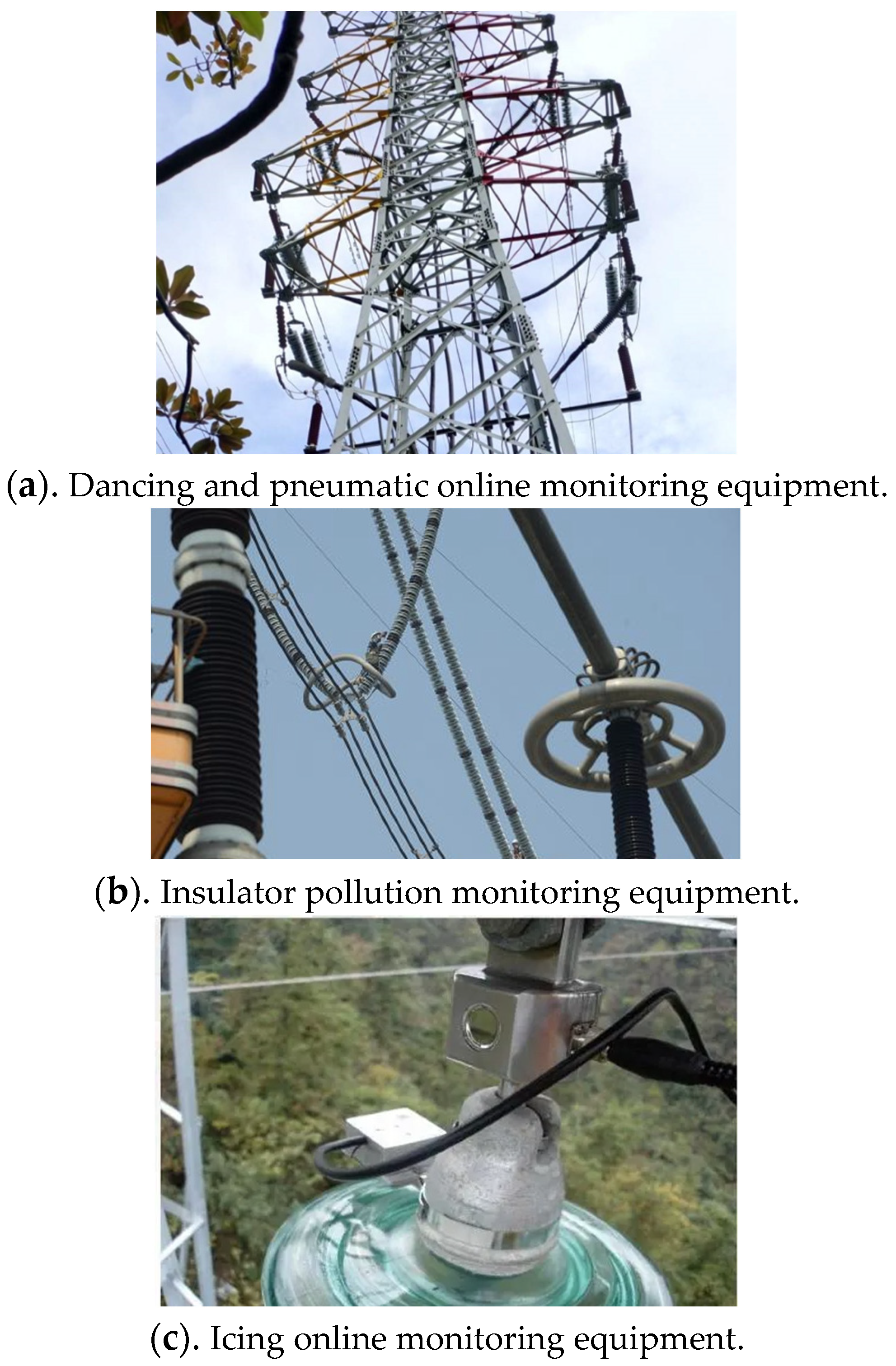
  • Solar power: It collects photovoltaic energy mainly through solar cell arrays, and, at the same time, for online monitoring devices and battery power supplies. However, solar cells are susceptible to weather conditions, and the storage capacity in solar power systems is unlikely to be too large when it is cloudy and rainy for many days; hence, solar power systems may not be able to meet the power needs of online monitoring devices [7].
  • Laser power: At the low-voltage side, high-power laser generators are used to send light energy to the high-voltage side, and at the high-voltage side, photocells are used to convert light energy into electricity, which supplies power to high-voltage lines [8]. However, due to the large size of the transmitting and receiving devices and the fact that online detection equipment is usually installed on high-voltage lines, it is difficult to install power supply equipment, and the cost of its operation and maintenance is high.
  • Ultrasonic power supply: The utility model relates to an energy supply mode that uses ultrasonic waves as a medium to transmit electric energy. However, its equipment is expensive, and the conversion efficiency is low. Hence, it cannot be used on a large scale.
  • Microwave power: It is a means of transmitting energy in a vacuum or in the atmosphere without the aid of any other transmission lines. However, if a microwave power supply is applied to the power supply of online monitoring devices for high-voltage transmission lines, there is also a need to address the design and placement of receiving antennas, determining whether the microwave power supply can interfere with monitoring devices, and the issues surrounding operation and maintenance [9].
In order to optimize the real-time power supply for online monitoring devices of high-voltage transmission lines, this paper proposes a power supply mode combining current transformer power extraction technology and three-coil wireless power transmission (WPT) technology. Compared with the above four energy supply modes, the current transformer has the advantages of small size, low cost, high transmission power, and not being affected by weather changes. In addition, the use of current transformer energy technology can avoid direct contact with energy sources and can solve the problem of insulation in the power supply [10,11,12,13]. In addition, compared with other wireless energy transmission technologies, the magnetic coupling resonant WPT technology has the advantages of a long transmission distance, high transmission power, high transmission efficiency, physical isolation, etc. [14,15]. The combination of CT induction power extraction technology and three-coil WPT technology can provide an appropriate solution to the problem of power supply insulation for online monitoring devices of high-voltage transmission lines [16].
In [4], according to the limitation of the plant application of induction energy harvesting devices for high-voltage transmission lines, several power supply modes are compared and the power supply mode of solar panels and accumulators is put forward. In order to deal with bad situations after magnetic saturation, silicon steel sheets with high-saturation permeability and low cost are used as the core material. In [5], based on the method of obtaining electricity through CT induction acquisition technology, a device for obtaining electricity is designed. The output power reaches 3 W. Two kinds of output voltage grades are provided. The maximum output current can reach 250 mA, and the utility model solves the power supply problem of the equipment in the power tunnel. In [6], a simple model of self-supply power is designed based on the analysis of circuit structure and take-up coil by using the principle of CT induction acquisition technology taking-up power for power overhead lines; the take-up power is approximately 5 W and is applied to the fault detection of high-voltage transmission lines.
At present, research surrounding power supply methods for online detection equipment based on the combination of CT induction power extraction technology and three-coil WPT technology is in the initial stages. There are still some problems, such as limitations in the transmission distance and the insufficient antisaturation ability of the magnetic core, leading to a high degree of magnetic saturation.

1.3. Contribution and Paper Organization

This paper presents an induction power extraction and three-coil WPT technology for high-voltage transmission lines. In this paper, the structure parameters of the CT ring are analyzed and the influence of the coil parameters on the energy efficiency of the magnetic coupling WPT system is analyzed. Based on this, this paper optimizes the structural and coil parameters of the CT ring, finally making the system have a larger induced voltage in the energy-fetching link. At the same time, the system has a longer transmission distance, improved size and cost of the equipment, and improved stability and practicability.
This paper first analyzes the principle of inductive energy acquisition and the principle of the magnetic coupling resonance wireless power transmission, which provides a theoretical basis for the proposal of the new method. Then, through the analysis and calculation of the influence of each structural parameter, the optimal parameter is selected and verified through a simulation. Finally, a three-coil CT inductive energy acquisition system with a longer transmission distance and a larger induced energy acquisition voltage is obtained.

2. Theoretical Analysis and Design of Induction Power Extraction

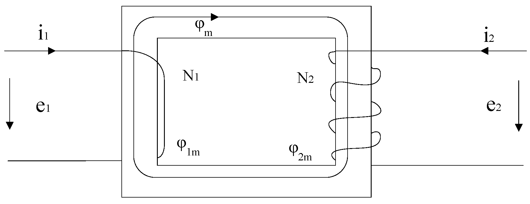
2.1. Analysis of CT Ring Induction Power Extraction

A CT-type induction power extraction model was adopted for the induction power extraction of high-voltage transmission lines. The current transformer was composed of a high-voltage transmission line on the primary side, a core, and a secondary winding. The current transformer was based on the principle of electromagnetic induction. When the alternating current passes the primary side of the high-voltage transmission line, induced in the secondary side with the same phase, the amplitude is proportional to the number of turns [17]. The primary side current is not affected by the secondary side, and the secondary side current is not affected by the load, which is only related to the primary side current and the core and winding [18]. When establishing the mathematical model of CT induction power extraction technology, the skin and temperature effects of the winding were ignored, and the hysteresis eddy current loss of the core was also ignored. The magnetic coupling model of the power extraction CT is shown in Figure 1. The primary side was controlled through an alternating current and only had one turn of winding on it. In Figure 1, φm is the main magnetic flux, φ1m and φ2m are the leakage fluxes of the primary and secondary winding, respectively, φ1 and φ2 are the main magnetic fluxes of the primary and secondary winding, respectively, i1 and i2 are the currents of the primary and secondary winding, respectively, N1 and N2 are the turns of the primary and secondary winding, respectively, and e1 and e2 are the potentials of the primary and secondary winding, respectively.
The voltage effective value of the CT secondary side under no-load conditions was expressed as:
E 2 = 2 × 4.44 f N 2 μ 0 μ r S I 1 l
where μr is the relative permeability of the magnetic core, μ0 is the vacuum permeability, l is the effective magnetic circuit length, S is the cross-sectional area of the iron core, f is the frequency of the transmission line current, and I1 is the effective value of the transmission line current.

2.2. Selection of CT Ring

For the selection of the CT ring, a larger initial permeability and a larger saturation permeability were necessary. The most commonly used iron core materials are nanocrystal, permalloy, and silicon steel [19]. The parameters of the three materials are listed in Table 1. It can be seen that the saturation magnetic induction intensity of silicon steel was large, and it was not easy to make the magnetic core enter a saturated state, while the magnetic permeability of the nanocrystal and permalloy was much larger than that of the silicon steel. Considering the economy and practicability of CT involved in this paper, silicon steel was selected as the core material of CT.
The core was designed to open the air gap to improve the maximum saturation magnetic induction intensity of the air gap and suppress the core saturation. In this case, the antisaturation characteristics and demagnetization ability of the iron core increased and the performance of the traditional current transformer was improved. At the same time, this structure of air gap also provided convenience for the installation of the current transformer on the high-voltage transmission line.
The relative permeability of the iron core in the case of an open-air gap could be derived as:
μ r = μ F e μ F e δ l + 1 μ F e = 1 δ l + 1 μ F e δ l

2.3. Power Extraction of CT Ring

If the ring core of the current transformer was composed of a highly permeable material, it could be considered that the inductance of the primary and secondary sides of the current transformer was fully coupled, and the coupling coefficients of the primary and secondary sides were infinitely close to one. The current transformer was calculated using the mutual inductance model, and the equivalent circuit diagram is shown in Figure 2.
Without considering the saturation of the core, the expression of the maximum power could be derived as:
P m a x = ( ω 2 n 2 L 1 2   ω n 2 L 1 ) ( 2 ω 2 n 4 L 1 2 ) I 1 2 = 1 2 ω L 1 I 1 2
The above analysis of the maximum output power was based on an ideal state that the magnetic core was not saturated. In reality, the magnetic core would reach the saturation state with the increase in the primary side current. At this time, the current induced by the secondary side of the current transformer would be used for excitation, and significantly increasing the excitation current. The output current at the primary side would present with serious distortion, and the permeability of the magnetic core would also be significantly reduced, affecting the normal operation of the current transformer. If the equivalent resistance of the secondary side was not controlled to continuously increase to output higher power, it may lead to the saturation of the magnetic core. Therefore, it is necessary to calculate and discuss the state that may lead to core saturation.
The equivalent resistance of the secondary side could be adjusted to make the magnetic core not enter the saturated state when it was saturated. The maximum power output under the unsaturated state of the magnetic core was expressed as:
P m a x = I 1 2 ( I 1 2 L 1 2 ) / ( B m a x S 2 ) 1 ω L 1 I 1 · B m a x S ω
where Bmax is the maximum magnetic induction intensity.

2.4. Power Extraction of CT Ring

The open-circuit voltage of the secondary side of the current transformer and the relative permeability of the iron core under the condition of an open-air gap could be calculated so that the current transformer could be equivalent to an ideal voltage source.
The parameters of the current transformer designed in this paper were given as follows: outer diameter R0 = 44 mm; inner diameter Ri = 30 mm; width a = 30 mm; air gap δ = 1 mm; secondary side turns N2 = 200; vacuum permeability μ0 = 4π × 10−7 H/m; system frequency f = 50 Hz.
By combining (1) and (2), the expression of the secondary open-circuit voltage after opening the air gap could be obtained as:
E 2 = 2 × 4.44 f N 2 μ 0 S I 1 δ
When the input voltage was 500 A, it could be concluded that the effective value of the open-circuit voltage on the secondary side of the current transformer was obtained as:
E 2 = 16.57   V
Therefore, the current transformer could be equivalent to an AC voltage source with an amplitude of 1.414 E2. It was shown that, when the current at the transmission terminal was 500 A, it was equivalent to a voltage source with an amplitude of 23.43 V.

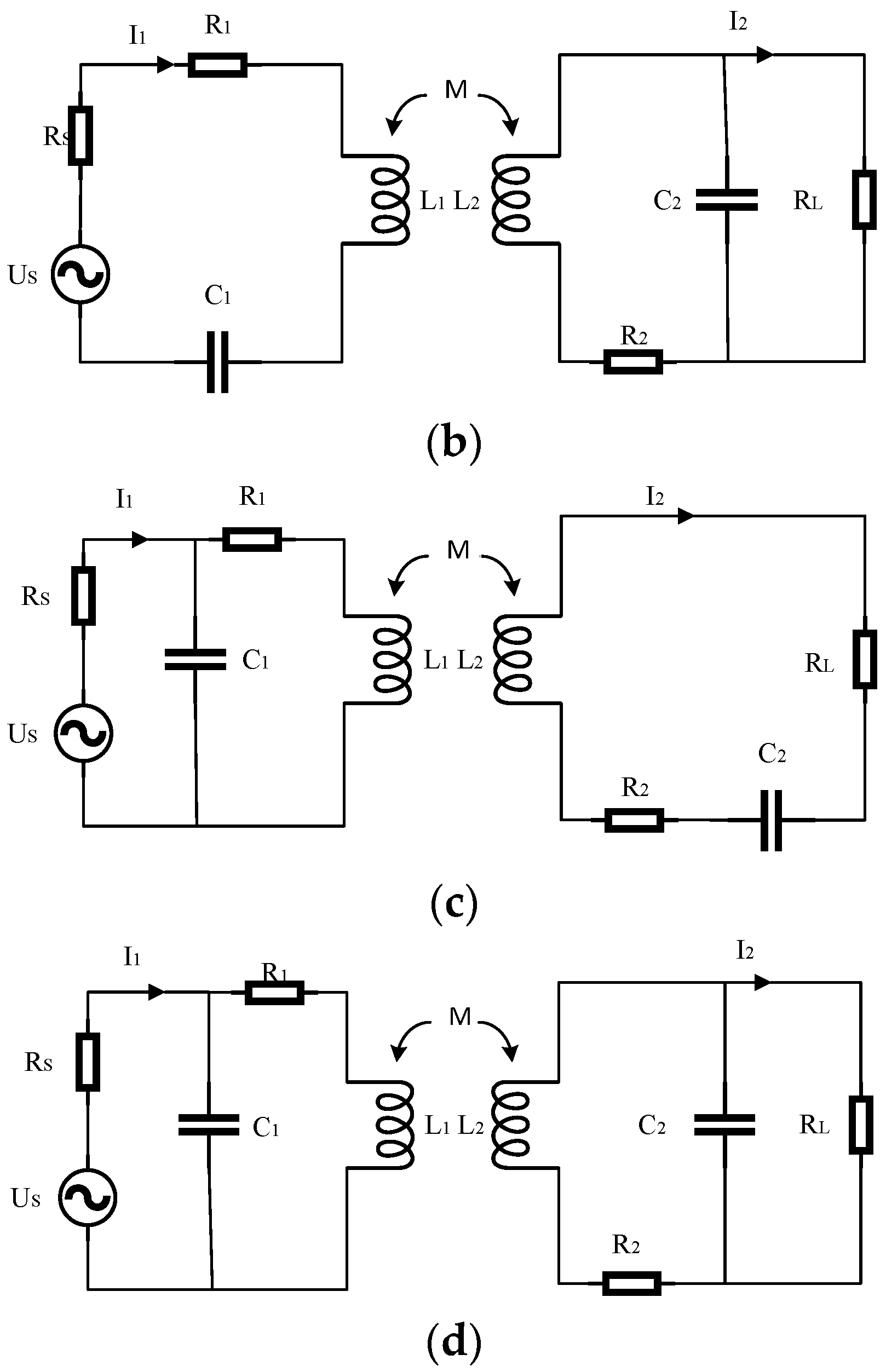
3. Theoretical Analysis and Design of Magnetic Coupling Resonant WPT System

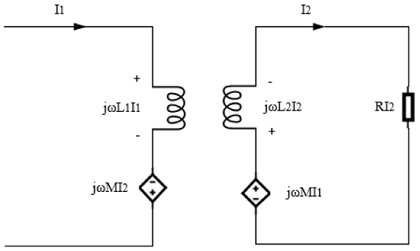
3.1. Mathematical Model of Magnetic Coupling Resonant Wireless Power Transmission System

According to the transmission coil and the receiving coil capacitor compensation, there were four basic compensation topological spaces for the magnetically coupled resonant WPT, as shown in Figure 3.
Through the calculation of the four topological equivalent circuits, the output power, transmission efficiency, and compensation capacitance of the magnetic coupling resonant wireless power transmission system under four structures could be obtained, as shown in Table 2 and Table 3.
It can be seen from Table 3 that the compensation capacitance of the transmitter was not affected by the load of the receiver, and it was only related to the system frequency and the self-inductance of the transmitter only in SS topology.
The transmission efficiency of the SS topology under resonant conditions could be obtained through the compensation capacitance expression.
η = ( ω 2 M 2 R L ) [ R 1 ( R 2 + R L ) + ω 2 M 2 ] ( R 2 + R L )
Similarly, the transmission efficiency of the other three topological spaces could be obtained. It could be found from the expression that the transmission efficiency expressions of the SS and PS topological spaces were the same, and the transmission efficiency expressions of the SP and PP topological spaces were the same. Hence, the transmission efficiency was not related to the structure of the transmitter, but to the receiver.
It could be known from the principle of series resonance that the reactance of the primary side of the SS topology was zero in the resonant state. The current of the primary side was large and the voltage was small in the resonant state because of the small resistance value of the coil. The output current of the secondary side was constant. The output power and transmission efficiency mainly depended on the mutual inductance, resonant frequency, and load resistance of the coupling coil.

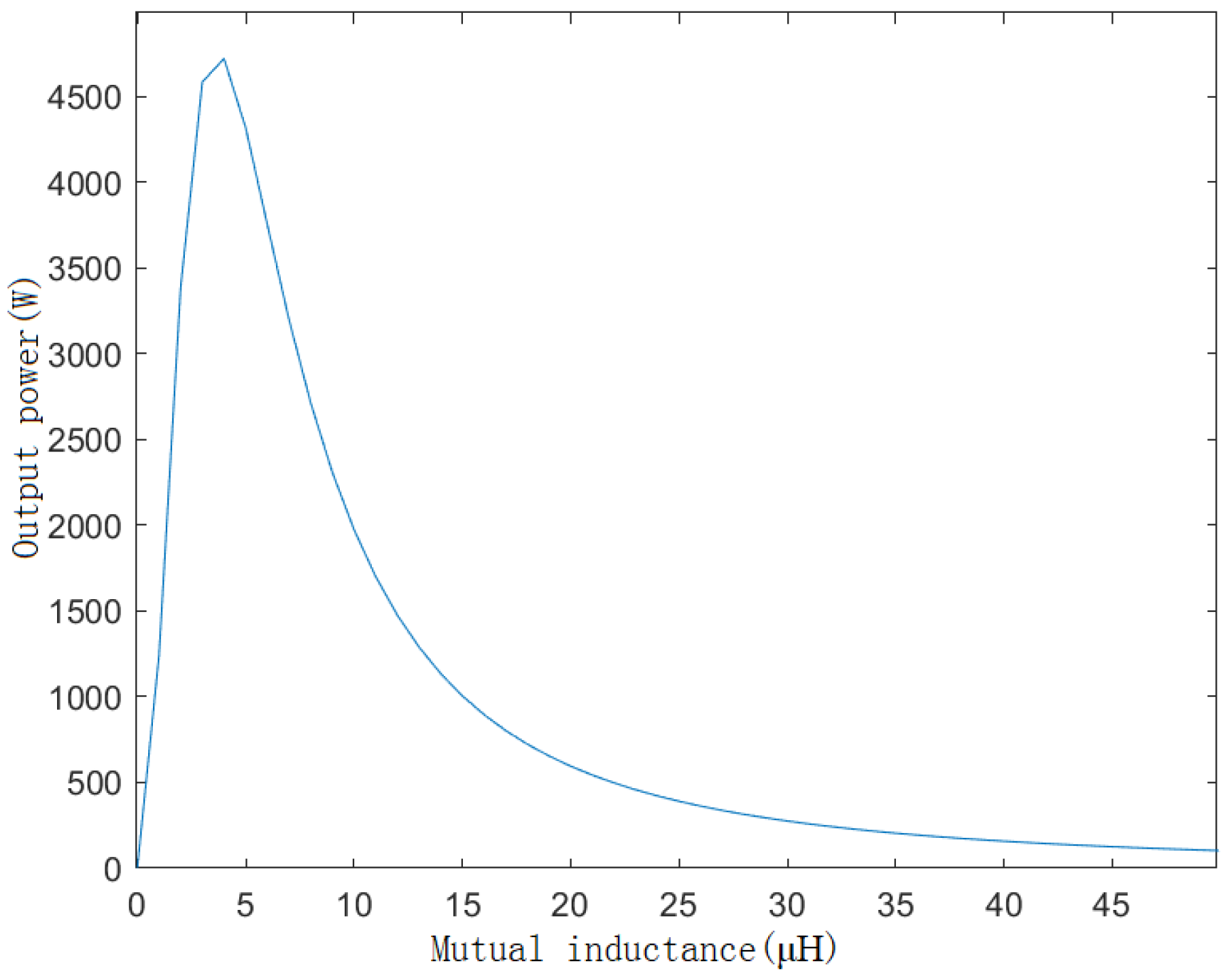
3.1.1. Relationships between Output Power, Transmission Efficiency, and Coil Mutual Inductance

The system frequency f was 100 kHZ, the input voltage was 100 V, the load resistance RL was =10 Ω, and the coil resistance R was 0.5 Ω. The relationship between the transmission power and efficiency with mutual inductance is shown in Figure 4 and Figure 5.
It can be seen from Figure 4 that the output power reached the maximum when the mutual inductance was close to 5 μH. It can be seen from Figure 5 that the transmission efficiency of the system tended to be stable and reached the maximum after the mutual inductance was 10 μH.

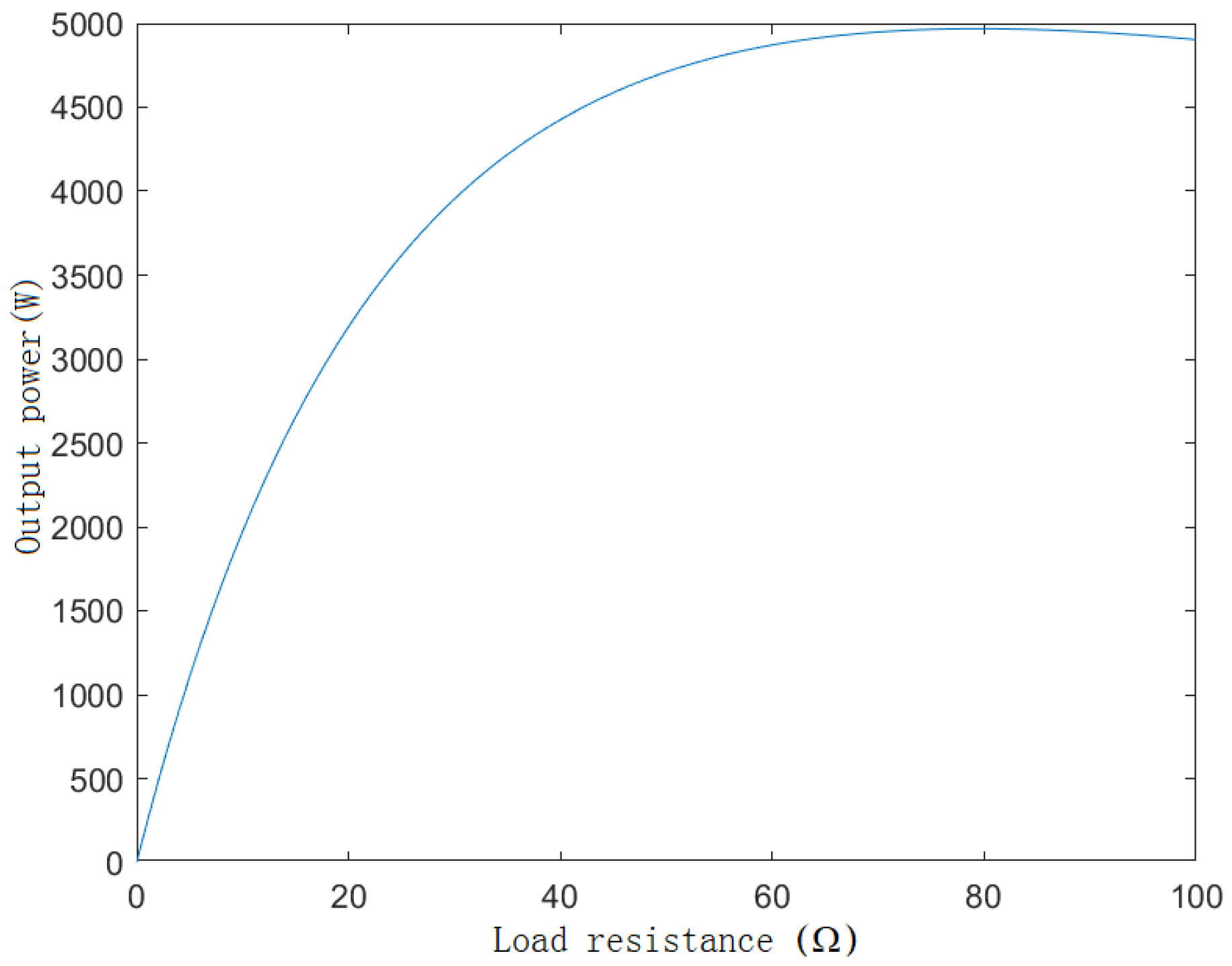
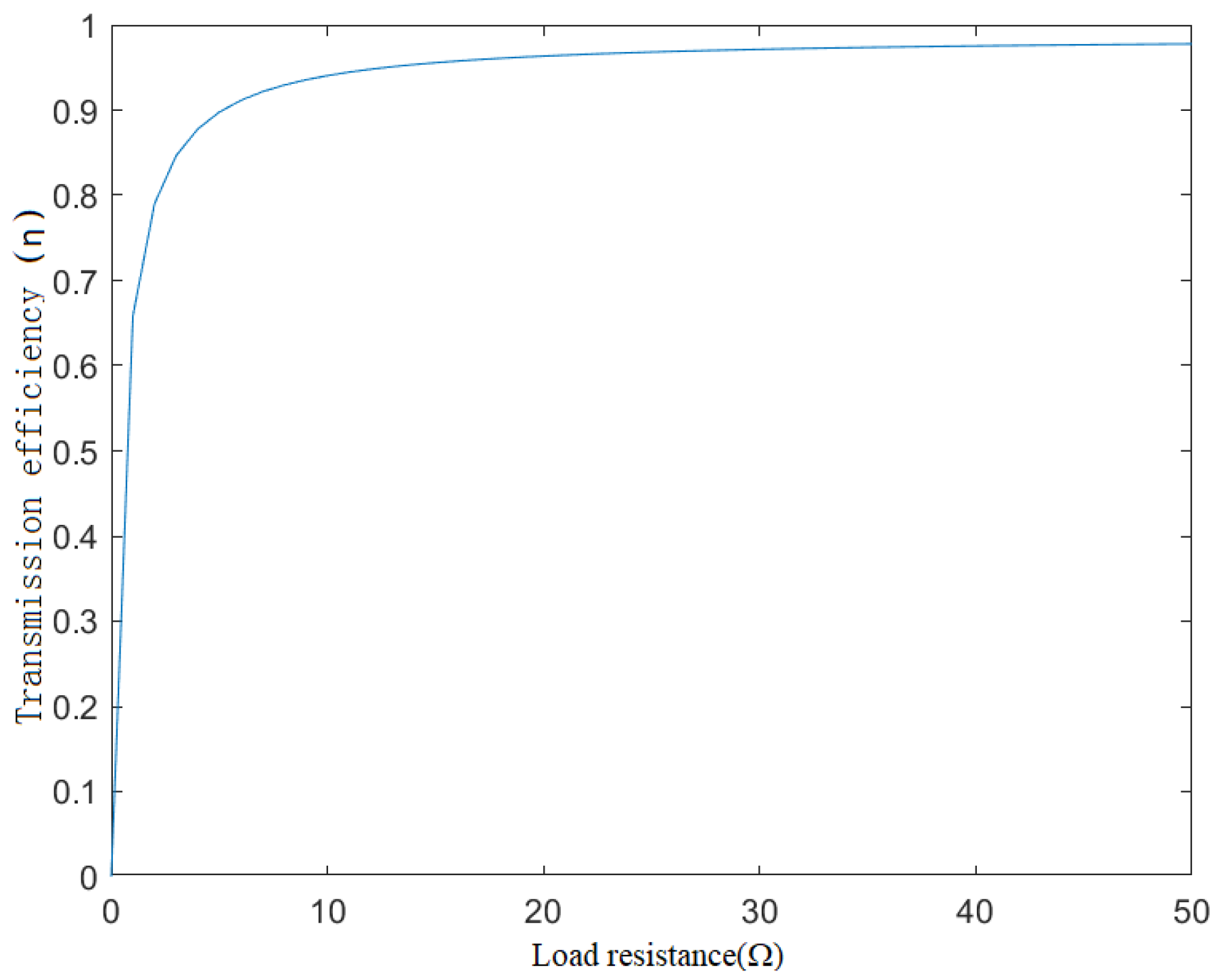
3.1.2. Relationships between Output Power, Transmission Efficiency, and Load Resistance

When the system frequency f was 100 kHz, the input voltage was 100 V, the coil mutual inductance was M = 100 μH, the coil resistance R was 0.5 Ω, the relationship between the transmission power and efficiency of the system with the load resistance is shown in Figure 6 and Figure 7.
It can be seen from Figure 6 that the output power increased gradually with the increase in load resistance. As seen from Figure 7, the transmission efficiency tended to be stable when the load resistance was higher than 30 Ω.

3.2. Theoretical Analysis of Three-Coil Magnetic Coupling Resonant WPT System

The multicoil WPT could be used to improve the distance of the WPT. The three-coil magnetic coupling resonant WPT system contained three different coils, which were the transmission coil connected to the high-frequency power supply, the relay coil, and the receiving coil with a load. As shown in Figure 8, based on the mutual inductance theory, the equivalent circuit model of the system was established by using the SS topology structure.
In Figure 8, US is the high-frequency voltage, R1, R2, R3, RS, and RL are the resistance of the transmitting coil, the resistance of the relay coil, the resistance of the receiving coil, the internal resistance of the power supply, and the resistance of the load, respectively; L1, L2, and L3 are three equivalent inductance values of the coil, and C1, C2, and C3 are the capacitor compensations of the three coils.
The output power and transmission efficiency of the system could be obtained by listing the KVL equation of the circuit model when the system was in a resonant state.
P o u t = I 3 2 R L = ( ω 2 M 1 2 M 2 3 ) 2 U S 2 R L [ ( ω M 1 2 ) 2 ( R 3 + R L ) + ( R S + R 1 ) [ R 2 ( R 3 + R L ) + ( ω M 2 3 ) 2 ] ] 2
η = ( ω M 1 2 2 M 2 3 2 R L ) ( R 2 ( R 3 + R L ) + ( ω M 2 3 ) 2 )   β
β = 1 ( ( ω M 1 2 ) 2 ( R 3 + R L ) + ( R S + R 1 ) [ R 2 ( R 3 + R L ) + ( ω M 2 3 ) 2 ] )

3.3. Analysis of Influence Factors of Three-Coil Magnetic Coupling Resonant WPT System

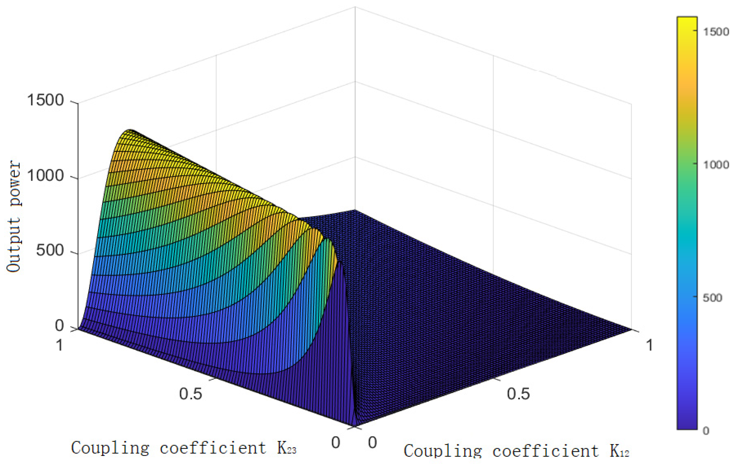
3.3.1. Effect of Coupling Coefficient on Output Power

In the three-coil WPT system, the distance between the receiving coil and the transmitting coil was large and the mutual inductance could be ignored. Hence, only the mutual inductance between the adjacent coils was considered. By substituting the coupling coefficient formula into the output power expression, it had:
P o u t = I 3 2 R L = ω 4   k 1 2 2   k 2 3 2   L 4 U S 2 R L [ ω 2   k 1 2 2 L 2 ( R 3 + R L ) + ( R S + R 1 ) [ R 2 ( R 3 + R L ) + ω 2   k 1 2 2 L 2 ] ] 2
where frequency f = 100 kHz, input voltage US = 100 V, R1 = R2 = R3 = R = 0.5 Ω, and L1 = L2 = L3 = L = 297.08 μH. Ignoring the internal resistance of the input power supply RS and making the load resistance value RL = 15 Ω, based on these parameters, the relationship between the coupling coefficient and the output power could be obtained, as shown in Figure 9.
As Figure 9 shows, the output power would appear to peak with the increase in the coupling coefficient, and the output power would decrease with the increase in the coupling coefficient if the coupling coefficient continued to increase. Therefore, the output power did not increase with the increase in the coupling factor.

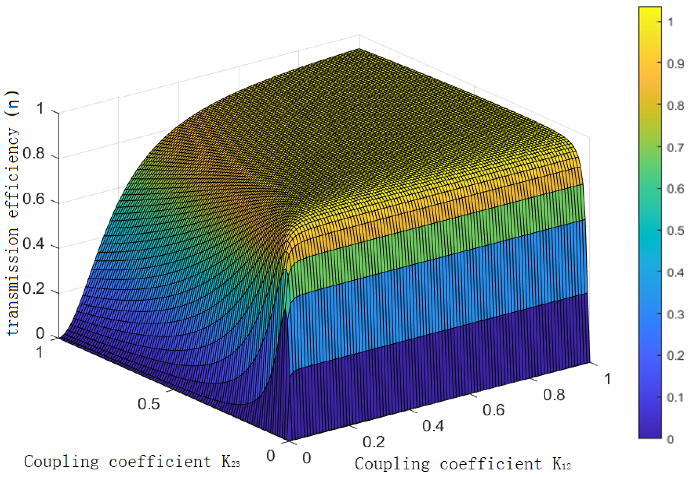
3.3.2. Influence of Coupling Coefficient on Transmission Efficiency

By substituting the coupling coefficient into the transmission efficiency formula, it had
η = ω k 1 2 2 k 2 3 2 L 4 R L R 2 ( R 3 + R L ) + ( ω k 2 3 L ) 2 × 1 ω 2 k 1 2 2 L 2 ( R 3 + R L ) + ( R S + R 1 ) [ R 2 ( R 3 + R L ) + ω 2 k 1 2 2 L 2 ]
Thus, the relationship between the coupling coefficient and the transmission efficiency could be obtained, as shown in Figure 10.
It could be seen from Figure 10 that when other parameters were determined, the transmission efficiency of the system increased with the increase in the coupling coefficients k12 and k23. Moreover, the influence of the coupling coefficient of the transmitting coil and the relay coil on the transmission efficiency of the system was slightly larger than that of the coupling coefficient of the relay coil and the receiving coil. Since the coupling coefficients k12 and k23 of the system had a certain negative correlation, it was difficult to make the transmission efficiency reach the maximum value. However, the transmission efficiency of the system would be improved with the increase in k12.

3.3.3. Determination of Three-Coil Parameters

The three-coil WPT system designed in this paper was used for 110 kV transmission lines. According to the electric power industry standard of China—technical code for designing 110~500 kV overhead transmission line—the insulation distance standard of transmission lines under different voltage levels could be found.
It can be seen from Table 4 that the insulation distance of the 110 kV transmission line was 1.022 m. Therefore, 1.2 m was taken as the transmission distance of the designed coil.
As the three-coil structure with a relay coil was used for power transmission, the position of the relay coil would affect the transmission performance of the system. In the three coils designed in this paper, the distance between the transmitting coil and the receiving coil was 1.2 m, and the relay coil was placed in the center of the transmitting coil and the receiving coil. Three coils adopted the same planar spiral coil structure, and the coil parameters are listed in Table 5.
The coil was modeled in Maxwell with the selected parameters, and the magnetic field intensity distribution of the coil is shown in Figure 11.

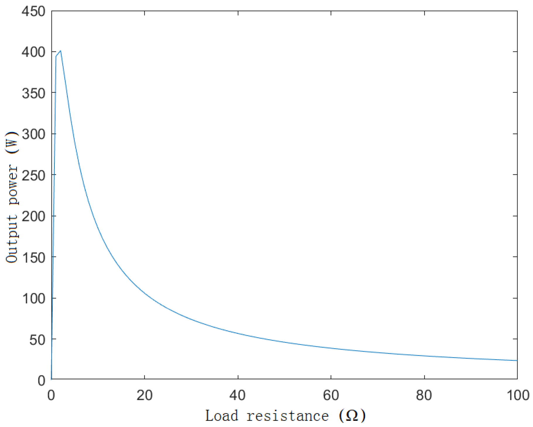
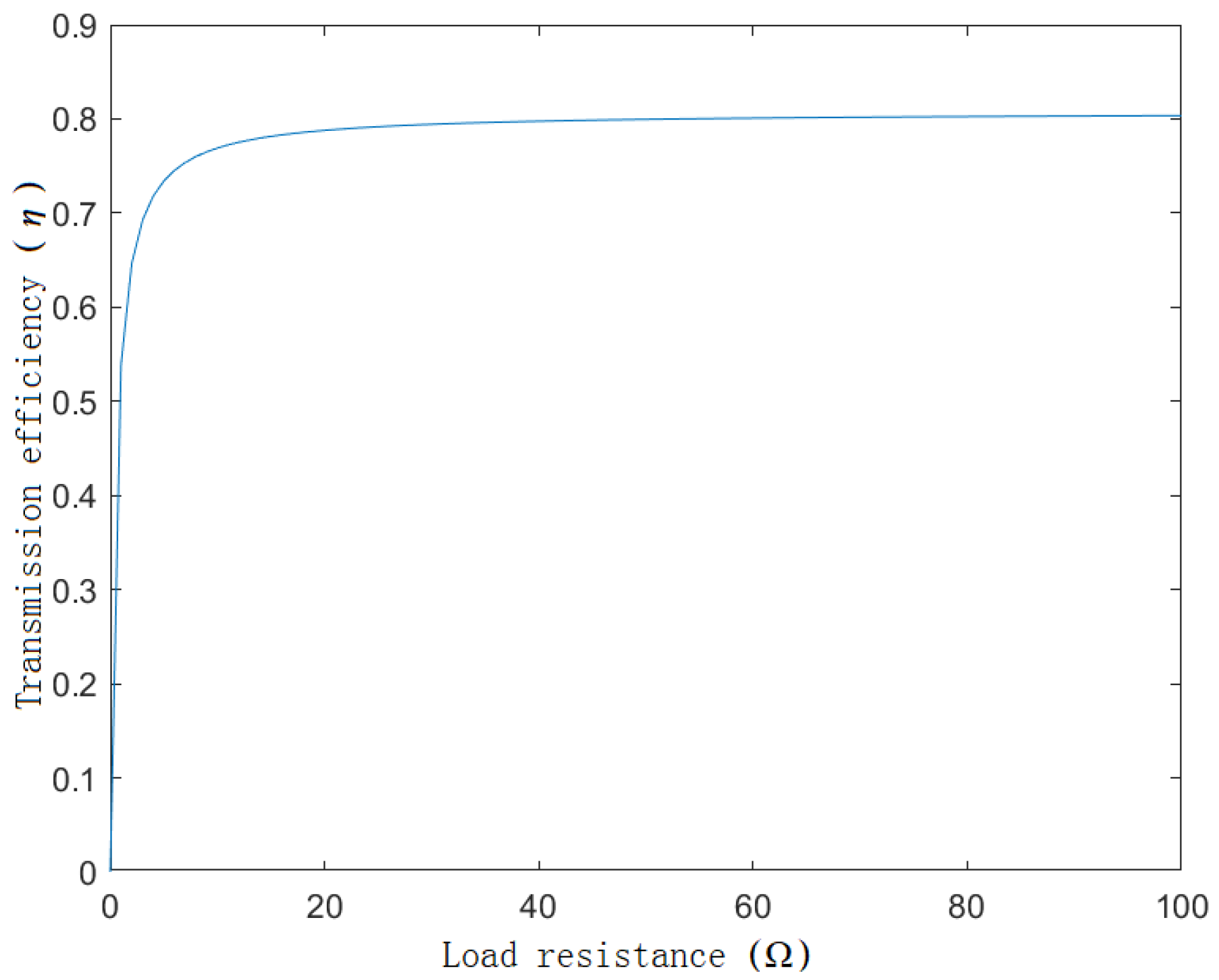
3.3.4. Influence of Load Resistance on Transmission Performance
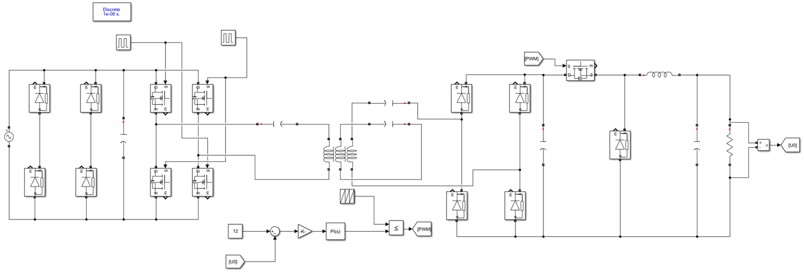
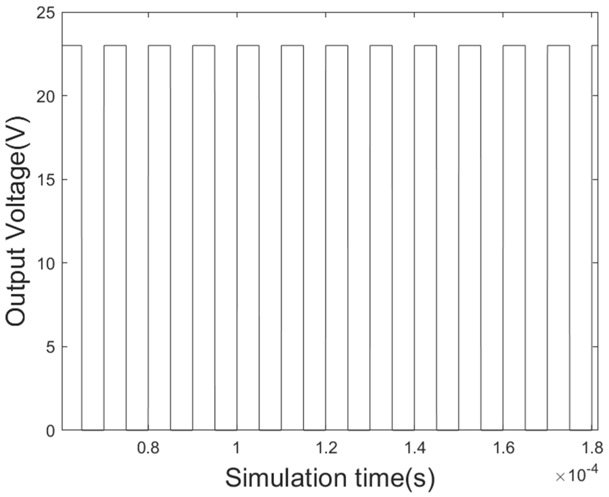
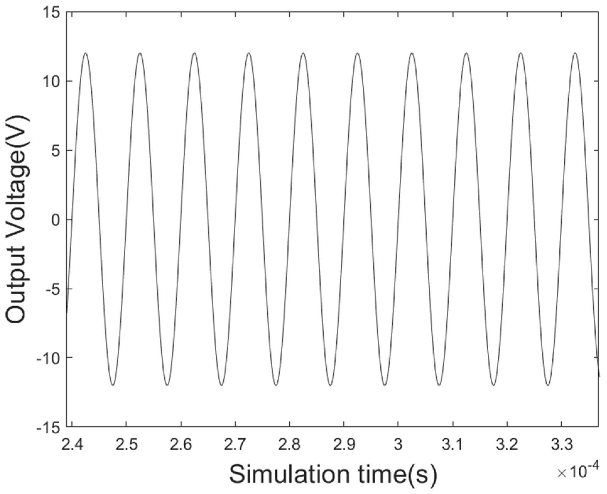
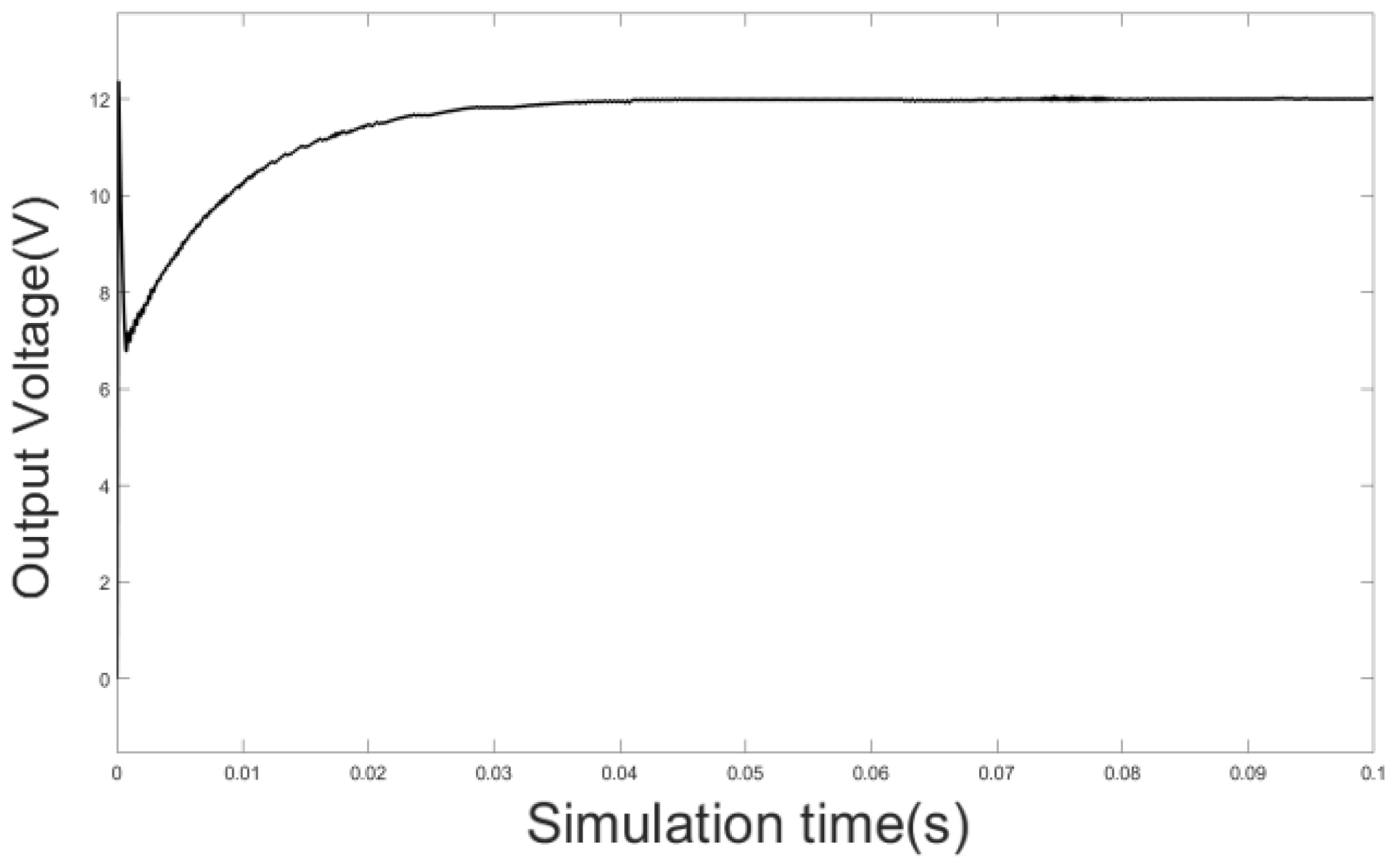
The mathematical model of the three-coil WPT system was modeled and analyzed in Maxwell. The coil diameter was 0.2 cm, the coil inner diameter was 20 cm, the coil outer diameter was 32 cm, and there were 20 coil turns. The self-inductance and mutual inductance of the simulation coil were L1 = L2 = L3 = L = 297.08 μH and M12 = M23 = 10.315 μH, respectively. The coil resistance was R1 = R2 = R3 = R = 0.5 Ω, the input voltage US was =100 V, and the resonant frequency f was =100 kHz. Based on the above parameters, the load, output power, and transmission efficiency curves are shown in Figure 12 and Figure 13.
From Figure 12, it could be seen that the output power increased sharply with the increase in resistance. It decreased rapidly and, finally, the trends slowed down when it reached the peak value. It could be observed from Figure 13 that the transmission efficiency increased rapidly with the increase in resistance value when the resistance value was very small. It tended to be stable, reaching approximately 80% when the load resistance reached approximately 10 Ω.

4. Simulation

The current transformer was equivalent to an ideal voltage source through the above analysis and calculation. It was connected to an uncontrolled rectifier circuit and was filtered through the capacitance. Through the high-frequency inverter circuit, the direct current was transformed into an alternating current with a frequency of 100 kHz, and was connected to the three-coil system. Then, it was connected to a bridge rectifier circuit and capacitor filter. Finally, a 12 V voltage was output into the load through the Buck converter circuit. The simulation circuit is shown in Figure 14.
Based on the above simulation parameters, the load resistance was set to be 10 Ω. The inverter output voltage, the receiving coil output voltage, and the system simulation output voltage waveforms were simulated, as shown in Figure 15, Figure 16 and Figure 17.
It can be seen from Figure 15 and Figure 16 that the system worked stably and could realize a normal WPT. As seen from Figure 17, the system output power was 14.4 W. As shown in Figure 18, at present, from the perspective of the monitoring functions, common online monitoring equipment for high-voltage transmission lines could basically be divided into the following categories: icing monitoring, line galloping, and wind deviation monitoring, lightning monitoring, insulator pollution monitoring, tower tilt monitoring, etc. Due to the different energy consumptions of online monitoring devices with different functions, generally speaking, it was approximately 10 W, and the output power met the energy supply demand. Therefore, the system had practical application prospects.

5. The Innovation of the Paper

  • This paper discussed a new power supply mode of online detecting equipment for high-voltage transmission lines, which included CT induction power extraction technology and three-coil WPT.
  • The designed method of the CT induction power extraction devices was presented, related parameters, such as the material structure of the iron core, were given, and the optimization was verified.
  • The three-coil system with a relay coil was analyzed theoretically and the energy efficiency effect of related parameters of the three-coil system was analyzed. Based on this, a three-coil WPT system was designed.

6. Comparative Analysis

Due to a lack of research on the combination of CT-induced energy harvesting and three-coil WPT, the following Table 6 only compared and analyzed CT-induced energy harvesting:
Through the above table, it could be concluded that through the design of the open-air gap of the iron core and the optimization of the related parameters, the antisaturation ability of the designed CT had a greater induction voltage of the energy-taking link. At the same time, in combining with the three-coil WPT technology, the system had a longer transmission distance. In addition, the system designed in this paper reduced the equipment’s size and cost, increasing the system’s stability and efficiency.

7. Conclusions

Focusing on the shortcomings of the battery life cycle in traditional battery power supply modes of high-voltage transmission line online monitoring devices, this paper proposed a way to realize an online power supply by combining induction power extraction technology with three-coil WPT technology. In this paper, the structure and parameters of the whole system were selected and optimized, and the correctness of the theoretical analysis was verified with simulation results. The research results showed that the proposed system had good theoretical significance and practical application value for the wireless online power supply of online monitoring devices of high-voltage transmission lines.

8. Patents

This section is not mandatory but may be added if there are patents resulting from the work reported in this manuscript.

Author Contributions

W.L. and Y.C. constructed the models and analyzed the parameter design methods. Y.C. carried out the simulations. W.L. and Z.P. developed a theoretical feasibility derivation. X.W. and C.X. carried out the background research and concept mapping. C.X. carried out the supervision. All authors have read and agreed to the published version of the manuscript.

Funding

This research was funded by the 2020 Anhui Provincial Natural Science Foundation Energy Internet Joint Fund Project (no. 2008085 UD14).

Data Availability Statement

No new data were created.

Conflicts of Interest

The authors declare no conflict of interest.

Notations

SymbolDescriptionUnit
φmthe main magnetic fluxWb
φ1mthe leakage fluxes of the primary windingWb
φ2mthe leakage fluxes of the secondary windingWb
φ1the main fluxes of the primary windingWb
φ2the main fluxes of the secondary windingWb
i1the current of the primary windingmA
i2the current of the secondary windingmA
N1the turns of the primary winding-
N2the turns of the secondary winding-
e1the potentials of the primary windingV
e2the potentials of the secondary windingV
E2the voltage effective value of the CT secondary side under no-load conditionsV
μrthe relative permeability of the magnetic coreH/m
μ0the vacuum permeabilityH/m
lthe effective magnetic circuit lengthm
Sthe cross-sectional area of the iron corem2
fthe frequency of the transmission line currentHz
I1the effective value of the transmission line currentmA
μFethe ferrum permeabilityH/m
ωthe resonant angular frequencyr/s
Mthe mutual inductance factorH
R1the primary impedanceΩ
R2the secondary impedanceΩ
RLthe load resistanceΩ
Pmaxthe expression of the maximum powerW
Bmaxthe maximum magnetic induction intensityWb/m2
ηthe transmission efficiency-
Poutthe output powerW

References

  1. Zhai, Y.; Sun, Y.; Dai, X.; Su, Y.; Wang, Z. Modeling and Analysis of Magnetic Resonance Mode Wireless Power Transfer System. Chin. J. Electr. Eng. 2012, 32, 155–160. [Google Scholar]
  2. Jiao, B.; Fu, W.; Zhao, D. Design of CT energy source for high-voltage transmission lines. Power Technol. 2013, 37, 130–133. [Google Scholar]
  3. Zhang, X. Research on Multi-Coil Magnetic Coupling Resonant Wireless Power Transmission System; North China Electric Power University: Beijing, China, 2019. [Google Scholar]
  4. Rong, E. Research on the Key Technology of Inductive Power Taking of Transmission Lines and Design of Power Taking Device; Kunming University of Science and Technology: Kunming, China, 2019. [Google Scholar]
  5. Wang, Y.; Yang, Z.; Li, S. Design of non-contact high-efficiency induction power-taking transformer for power cables. Power Technol. 2013, 37, 459–460+474. [Google Scholar]
  6. He, X.; Wang, X. Design of high voltage line fault detection device. Instrum. Technol. Sens. 2015, 12, 32–35. [Google Scholar]
  7. Zhuang, Y.; Xu, C.; Song, C.; Chen, A.; Lee, W.; Huang, Y.; Zhou, J. Improving Current Transformer-based energy extraction from AC power lines by manipulating magnetic field. IEEE Trans. Ind. Electron. 2019, 67, 9471–9479. [Google Scholar] [CrossRef]
  8. Wang, W. Research on Key Technologies of Wireless Energy Supply for High-Voltage Transmission Line Online Monitoring Device and System Optimization Design; Southeast University: Nanjing, China, 2017. [Google Scholar]
  9. Chen, C. Optimization Analysis and Realization of High-Voltage CT Online Energy Harvesting Device; Shandong University: Jinan, China, 2017. [Google Scholar]
  10. Xie, Z.; Bi, T.; Jin, H.; Li, Y. Research on power supply of high-voltage transmission and distribution line online monitoring device. Electr. Meas. Instrum. 2016, 53, 16–21. [Google Scholar]
  11. Vos, M.J. A Magnetic Core Permeance Model for Inductive Power Harvesting. IEEE Trans. Power Electron. 2020, 35, 3627–3635. [Google Scholar] [CrossRef]
  12. Hou, J.; Wang, S.; Zhang, S.; She, Q.; Zhu, Y.; Li, C. Design and Application of a CT-Based High-Reliability Energy Harvesting Circuit for Monitoring Sensors in Power System. IEEE Access 2019, 7, 149039–149051. [Google Scholar] [CrossRef]
  13. Liu, Z.; Li, Y.; Yang, H.; Na, D.; He, Z. An Accurate Model of Magnetic Energy Harvester in the Saturated Region for Harvesting Maximum Power: Analysis, Design and Experimental Verification. IEEE Trans. Ind. Electron. 2022, 70, 276–285. [Google Scholar] [CrossRef]
  14. Long, M. Research and Design of Power Supply System for High-Voltage Line Monitoring Device Based on Magnetic Resonance Coupling; Wuhan University: Wuhan, China, 2018. [Google Scholar]
  15. Huang, Z.; Zou, J.; Wang, Y.; Wang, L. Research on WPT technology based on relay coil and its application in high-voltage equipment. J. Electrotech. Technol. 2015, 30, 45–52. [Google Scholar]
  16. Li, H. Research on High Frequency Wireless Power Transmission Technology Based on Relay Coil; Harbin Institute of Technology: Harbin, China, 2020. [Google Scholar]
  17. Zhang, C.; Tang, N.; Zhong, W.; Lee, C.K.; Hui, R.S.Y. A new energy harvesting and wireless power transfer system for Smart Grid. In Proceedings of the 2016 IEEE 7th International Symposium on Power Electronics for Distributed Generation Systems (PEDG), Vancouver, BC, Canada, 27–30 June 2016. [Google Scholar]
  18. Jiang, R.; Yan, S.; Deng, C.; Wang, Q.; Zhao, Y.; Tang, H.; Pan, J. Electric Field Analysis and Insulation Design of Wireless Power Transfer Coils Under High-Voltage Stress. In Proceedings of the 2022 IEEE International Conference on High Voltage Engineering and Applications (ICHVE), Chongqing, China, 25–29 September 2022. [Google Scholar]
  19. Hou, X.; Su, Y.; Liu, Z.; Deng, Z. Wireless Power Transfer System of On-line Monitoring device for High Voltage Transmission Line Based on Double-sided LCC Resonant Network. In Proceedings of the 2021 IEEE PELS Workshop on Emerging Technologies: Wireless Power Transfer (WoW), San Diego, CA, USA, 1–4 June 2021; pp. 1–5. [Google Scholar]
Figure 1. CT coupling relationship power extraction diagram.
Energies 16 03079 g001
Figure 2. Current transformer equivalent circuit diagram.
Energies 16 03079 g002
Figure 3. Equivalent circuit of topological structure: (a) SS topology structure; (b) SP topology structure; (c) PS topology structure; (d) PP topology structure.
Energies 16 03079 g003aEnergies 16 03079 g003b
Figure 4. Relationship between output power and mutual inductance.
Energies 16 03079 g004
Figure 5. Relationship between transmission efficiency and mutual inductance.
Energies 16 03079 g005
Figure 6. Relationship between output power and load resistance under the two coils.
Energies 16 03079 g006
Figure 7. Relationship between transmission efficiency and load resistance under the two coils.
Energies 16 03079 g007
Figure 8. Three-coil magnetic coupling resonant wireless power transmission system circuit model.
Energies 16 03079 g008
Figure 9. Relationship between output power and coupling coefficients k12 and k23.
Energies 16 03079 g009
Figure 10. Relationship between transmission efficiency and coupling coefficients k12 and k23.
Energies 16 03079 g010
Figure 11. Magnetic field distribution of three coils.
Energies 16 03079 g011
Figure 12. Relationship between output power and load resistance under the three coils.
Energies 16 03079 g012
Figure 13. Relationship between transmission efficiency and load resistance under the three coils.
Energies 16 03079 g013
Figure 14. System simulation circuit.
Energies 16 03079 g014
Figure 15. Voltage waveform of inverter output.
Energies 16 03079 g015
Figure 16. Voltage waveform of receiving coil output.
Energies 16 03079 g016
Figure 17. Voltage waveform of system simulation output.
Energies 16 03079 g017
Figure 18. Common high-voltage transmission line online monitoring equipment.
Energies 16 03079 g018
Table 1. Three core materials’ basic parameters.
Basic ParameterSilicon SteelPermalloyNanocrystal
Saturation induction (B/H)2.030.751.25
Initial permeability (μH/m)102~103(5~8) × 104(5~10) × 104
Maximum permeability (μH/m)4 × 10460 × 10460 × 104
Density (g/cm3)7.658.757.25
Packing fraction0.950.90.7
Thickness (mm)0.30.150.3
Table 2. Transmission characteristics of magnetically coupled resonant WPT.
Topological StructureOutput PowerTransmission Efficiency
SS ( ω M U S ) 2 R L ( Z 11 Z 21 + ω 2 M 2 ) 2 ω 2 M 2 R L ( Z 11 Z 21 + ω 2 M 2 ) Z 21
SP ( ω M U S ) 2 R L ( Z 11 Z 22 + ω 2 M 2 ) 2 ( 1 + j ω C 2 ) ω 2 M 2 R L ( Z 11 Z 22 + ω 2 M 2 ) ( 1 + j ω C 2 R L )
PS ( ω M U S ) 2 R L ( Z 12 Z 21 + ω 2 M 2 ) 2 ω 2 M 2 R L ( Z 12 Z 21 + ω 2 M 2 ) Z 21
PP ( ω M U S ) 2 R L ( Z 12 Z 22 + ω 2 M 2 ) 2 ( 1 + j ω C 2 ) ω 2 M 2 R L ( Z 12 Z 22 + ω 2 M 2 ) ( 1 + j ω C 2 R L )
Table 3. Compensation capacitance of magnetically coupled resonant WPT.
Topological StructureCompensation Capacitor C1Compensation Capacitor C2
SS 1 ω 2 L 1 1 ω 2 L 2
SP L 2 ω 2 ( L 1 L 2 M 2 ) 1 ω 2 L 2
PS L 1 R L 2 ω 2 L 1 2 R L 2 + ω 4 M 4 1 ω 2 L 2
PP L 1 L 2 M 2 L 2 2 ω 2 ( L 1 L 2 M 2 ) 2 + M 4 R L 2 L 2 2 1 ω 2 L 2
Table 4. Insulation distance under different voltage levels.
Voltage Level (kV)110220330500
Single Insulator Thickness
(mm)
146146146155
Number of Insulator7131725
Insulation Distance (m)1.0221.8982.4823.878
Table 5. Table of coil parameters.
Diameter of Wire
(cm)
Coil Diameter (cm)Outer Diameter of Coil (cm)Number of Coils
0.2203220
Table 6. Contrast table of CT-induced power extraction effect.
ReferenceMagnetic Core Material StructureAbility to Resist
Saturation
Induced Voltage at Current 500 A
Reference [4]C-coreWorse7.931 V
Reference [5]PermalloyWorse12 V
This articleSilicon steel, open-air gap structureMagnetic saturation decreased16.57 V
Disclaimer/Publisher’s Note: The statements, opinions and data contained in all publications are solely those of the individual author(s) and contributor(s) and not of MDPI and/or the editor(s). MDPI and/or the editor(s) disclaim responsibility for any injury to people or property resulting from any ideas, methods, instructions or products referred to in the content.

