Article

Hydrocarbon Generation Mechanism of Mixed Siliciclastic–Carbonate Shale: Implications from Semi–Closed Hydrous Pyrolysis

1
Research Institute of Experiment and Testing, PetroChina Xinjiang Oilfield Company, Karamay 834000, China
2
Key Laboratory of Metallogenic Prediction of Nonferrous Metals and Geological Environment Monitoring, Ministry of Education, Central South University, Changsha 410083, China
*
Author to whom correspondence should be addressed.
Energies 2023, 16(7), 3065; https://doi.org/10.3390/en16073065
Submission received: 27 February 2023 / Revised: 21 March 2023 / Accepted: 23 March 2023 / Published: 28 March 2023
(This article belongs to the Special Issue New Challenges in Unconventional Oil and Gas Reservoirs)

Abstract

:
Affected by the complex mechanism of organic–inorganic interactions, the generation–retention–expulsion model of mixed siliciclastic–carbonate sediments is more complicated than that of common siliciclastic and carbonate shale deposited in lacustrine and marine environments. In this study, mixed siliciclastic–carbonate shale from Lucaogou Formation in Junggar Basin was selected for semi–closed hydrous pyrolysis experiments, and seven experiments were conducted from room temperature to 300, 325, 350, 375, 400, 450, and 500 °C, respectively. The quantities and chemical composition of oil, gases, and bitumen were comprehensively analyzed. The results show that the hydrocarbon generation stage of shale in Lucaogou Formation can be divided into kerogen cracking stage (300–350 °C), peak oil generation stage (350–400 °C), wet gas generation stage (400–450 °C), and gas secondary cracking stage (450–500 °C). The liquid hydrocarbon yield (oil + bitumen) reached the peak of 720.42 mg/g TOC at 400 °C. The saturate, aromatic, resin, and asphaltine percentages of bitumen were similar to those of crude oil collected from Lucaogou Formation, indicating that semi–closed pyrolysis could stimulate the natural hydrocarbon generation process. Lucaogou shale does not strictly follow the “sequential” reaction model of kerogen, which is described as kerogen firstly generating the intermediate products of heavy hydrocarbon compounds (NSOs) and NSOs then cracking to generate oil and gas. Indeed, the results of this study show that the generation of oil and gas was synchronous with that of NSOs and followed the “alternate pathway” mechanism during the initial pyrolysis stage. The hydrocarbon expulsion efficiency sharply increased from an average of 27% to 97% at 450 °C, meaning that the shale retained considerable amounts of oil below 450 °C. The producible oil reached the peak yield of 515.45 mg/g TOC at 400 °C and was synchronous with liquid hydrocarbons. Therefore, 400 °C is considered the most suitable temperature for fracturing technology.

1. Introduction

In recent years, remarkable breakthroughs have been achieved in the exploration and development of shale oil and gas [1,2,3]. Hydrocarbon generation basically controls the accumulation of shale oil and gas, and the distribution of sweet spots. Previous studies have generally focused on common siliciclastic and carbonate shale deposited in lacustrine and marine environments, obtaining a deep understanding of the hydrocarbon generation process and key mechanism [4,5]. According to these studies, the thermal evolution and hydrocarbon generation of shale are affected by kerogen swelling and the double adsorption of shale by micro–/nanopores. The generated oil and gas can be expelled from the source rock when they reach the maximum adsorption/dissolution values of kerogen network pores and fractures [6,7,8]. Furthermore, the hydrocarbon generation process of organic matter in complex and variable lithological associations may be different from that of common silicate or carbonate shale. Therefore, a clear understanding of the coupling relationship between hydrocarbon generation and hydrocarbon expulsion can help directly determine the optimization of development objectives and the selection of reasonable mining methods. In the process of hydrocarbon generation, minerals (clay minerals, carbonate minerals, iron–bearing minerals, etc.) can catalyze or inhibit hydrocarbon generation by changing the reaction activation energy of reactants or increasing the frequency factor in the chemical reaction process; for instance, the secondary reaction of clay minerals in a closed system promotes the increase in gas yield [9,10,11], and calcite can hinder the secondary cracking of wet gases (C2–C5) into methane. The more complex the mineral composition is, the more difficult it is to describe its impact on hydrocarbon generation. The Middle Permian Lucaogou Formation might be a good example for developing a set of mixed siliciclastic–carbonate sediments. Briefly, Lucaogou Formation was deposited in a saline–alkali lacustrine environment, and the main lithology includes carbonate (limestone and dolomite), mud shale, and terrigenous clastic rock (mainly feldspar) [12,13,14]. Vertically, it can be divided into upper (P2l2) and lower (P2l1) sections. The sedimentary paleoenvironment of the upper section was weakly reducing and humid, with relatively low salinity, while that of the lower section was more strongly reducing and arid, with higher salinity. Due to good paleoproductivity and preservation conditions, Lucaogou Formation contains a set of high–quality hydrocarbon source rock deposits dominated by algal organic matter, with a thickness of 200–400 m, which are generally excellent low–maturity hydrocarbon source rocks (Ro: 0.59–1.25%), and the organic matter type is I–II2 [15].
Pyrolysis experiments might help understand the formation and evolution of oil and gas. Systematic thermal simulation experiments have been conducted on North American marine shale in open or closed systems [16,17,18,19]. Although these two experiments have simple methods and require only small amounts of samples, they have some disadvantages. In open systems, due to the lack of pressure restrictions, the generated hydrocarbons are quickly discharged from the system after generation; hence, the secondary cracking process of oil and gas cannot be simulated. In addition, due to insufficient reaction time, many olefinic intermediates are generated [20]. In closed systems, although the effect of secondary cracking is considered, the products generated continue to react in the system until the end of the experiment, which over–amplifies the effect of secondary cracking and produces high H2 yield, which is inconsistent with the site conditions [21]. Secondly, due to lacustrine shale being more vulnerable to the impact of climate change and related sea–level or lake–level changes, there are differences between the source rock and marine shale in terms of hydrocarbon–generating parent material, preservation abundance, and sedimentary lithofacies [22,23,24]. Therefore, it may be inappropriate to directly apply the thermal simulation experimental parameters obtained with marine shale to the lacustrine mixed siliciclastic–carbonate sediments of Lucaogou Formation, and it is urgent to build a dedicated hydrocarbon generation model.
Based on the burial history of Lucaogou Formation, this study conducted a semi–closed in situ transformation pyrolysis experiment on mixed siliciclastic–carbonate shale from Lucaogou Formation in the temperature range of 300–500 °C. We analyzed the hydrocarbon yield, and physical and chemical properties of generated, retained, and expelled oil and gases, and the carbon isotope characteristics of hydrocarbon gases during the immature–to–mature process. The objectives were to help establish a dynamic hydrocarbon generation–expulsion–retention model; to clarify the chemical fractionation process of oil and bitumen; to explore the mechanism of kerogen cracking to produce oil and gas; and to assess the producible oil from type I mixed siliciclastic–carbonate shale from Lucaogou Formation.

2. Materials and Methods

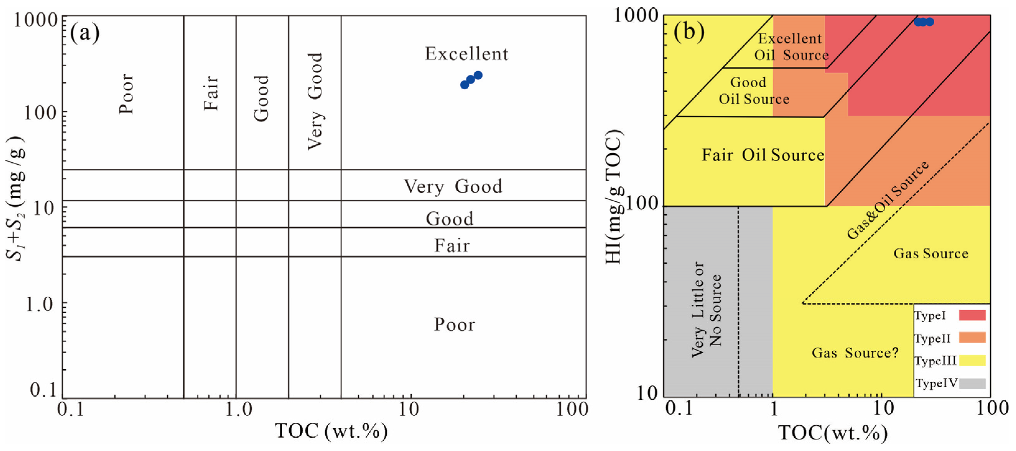
2.1. Samples and Characterization

One 500 g organic–rich core sample was collected from the upper section of Lucaogou formation (P2l2) in Jimusaer Sag by Xinjiang Oilfield Company (Karamay, China), at a coring depth of 3510.3–3510.4 m. According to the microscopic observations, the measured Ro was 0.6%. To ensure the accuracy and repeatability of the results, the whole rock was crushed to 40–60 mesh and uniformly mixed. Then, three small fractions (1–2 g) were randomly selected from the mixed samples for TOC and Rock–Eval analyses. The average values are shown in Table 1. The samples were rich in organic matter (the average TOC was 21.5%). The pyrolysis results (Tmax = 454 °C; HI = 970) and organic matter microscopic inspection results (TI = 80.1) show that the sample was characterized by type I organic matter (Figure 1). The XRD results show that the sample was mainly composed of quartz (82%), feldspar (9.7%), calcite (2.2%), and dolomite (1.5%), and small amounts of clay (1.8%) and pyrite (0.9%) and belonged to organic–rich mixed siliciclastic–carbonate shale. Due to its low maturity and high organic matter content, the sample was suitable for thermal simulation experiments. To prevent the high heterogeneity of the shale from impacting the experimental results, the sample was collected with a longitudinal span of no more than 10 cm.

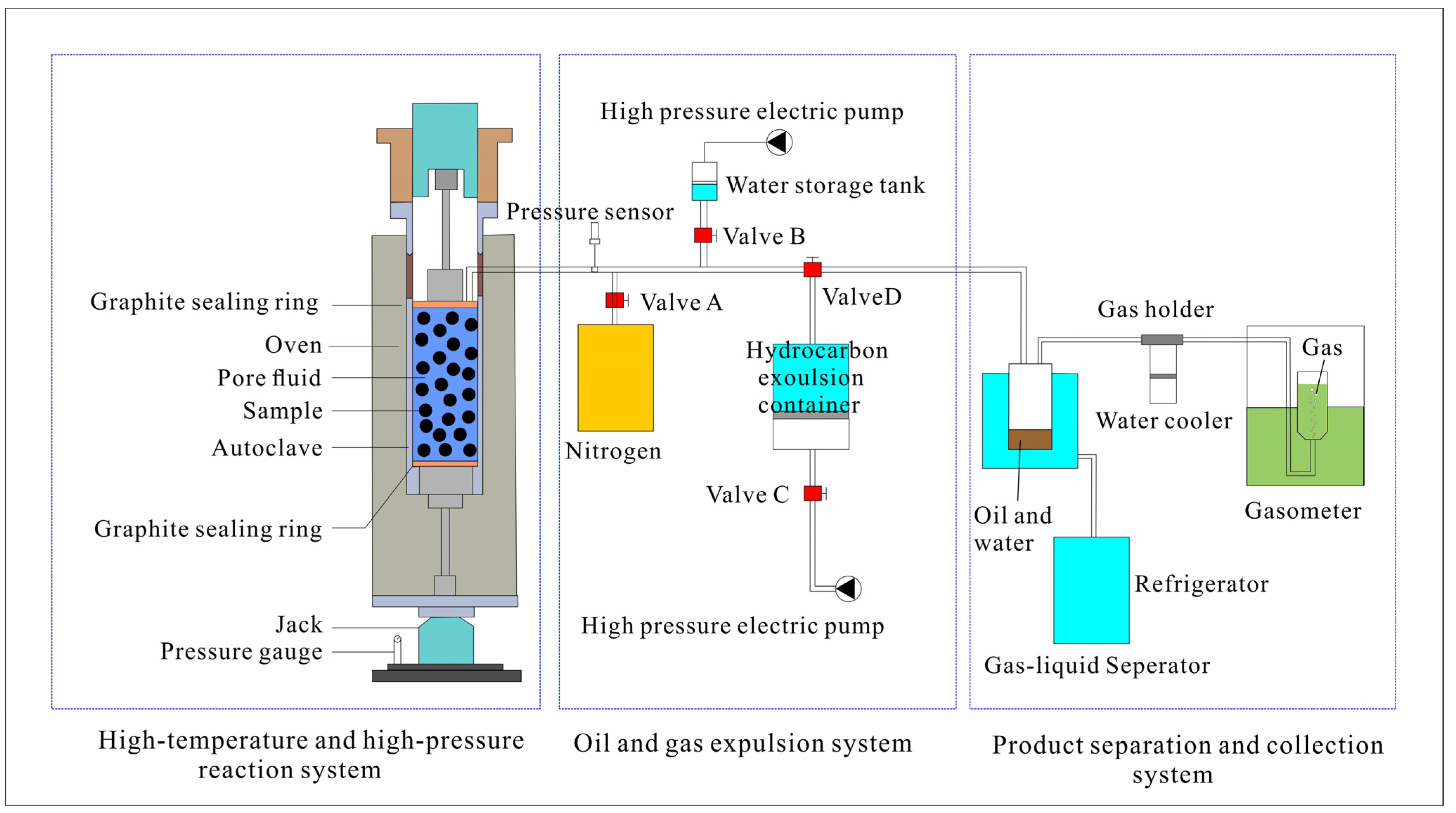
2.2. Semi–Closed Pyrolysis Experiments

The semi–closed hydrous system at high temperature and high pressure was selected for the experiment (Figure 2); its main advantage is that it can simulate actual geological conditions. The apparatus was composed of three main parts, including a high–temperature and high–pressure reaction system; an oil and gas hydrocarbon expulsion control system; and a product separation and collection system. The high–temperature, high–pressure reaction system was composed of a pressure application device, a heating device, and a sample cell. The hydrocarbon generation space was similar to the pore space, was completely filled with high–pressure water, and allowed the sample to be loaded under lithostatic pressure, fluid pressure, and confining pressure. The experimental heating temperature could reach 600 °C, and the maximum fluid pressure and lithostatic pressure were 1500 bar and 2500 bar, respectively. The maximum sample weight was 200 g. The oil and gas hydrocarbon expulsion control system was connected to the high–temperature, high–pressure reaction system through the back–pressure valve (D in Figure 2), which allowed the pressure limit to be flexibly set to control the expulsion of oil. During the generation of oil and gas, the system pressure increased accumulatively with the volume. When the pressure reached the set value, the valve automatically opened to discharge oil and gas. The product separation and collection system was used to separate and collect the liquid and gaseous products discharged after the valve was opened. The gas–liquid separation device was immersed in a Thermos cup connected to a refrigeration system to maximize the retention of light hydrocarbon components (C6–C14).
Seven parallel experiments were designed, with terminal temperature points of 300, 325, 350, 375, 400, 450, and 500 °C, to simulate the whole process, from immature to mature and over–mature. The direct heating method was used in this experiment. After the sample was crushed to 40–60 mesh, it was uniformly mixed and divided into seven equal parts and loaded into the sample cell. A small cylindrical core sample with a diameter of 3.5 cm was compressed using mechanical pressure. After a successful leak test, the pressure was applied using the rod of a two–way hydraulic press to apply lithostatic rock pressure to the core. The temperature controller was used to directly heat the sample from room temperature (21 °C) to the terminal temperature at a heating rate of 1 °C/min; then, the temperature was kept constant for 48 h. The detailed experimental procedure was previously reported by Ma et al. [27]. Generally, two heating rates were used in thermal simulation experiments, 2 °C (low rate) and 20 °C (high rate). Although previous thermal simulation experiments showed no significant differences in the final quantity yield of products at a low rate vs. high rate, the physical and chemical properties of the products were different. Therefore, to restore the real formation conditions to the maximum extent, a lower 1 °C/min heating rate was used.
During the experiment, the hydrocarbon expulsion value of each parallel experiment was not constant, and special boundary conditions (burial depth, lithostatic pressure, and fluid pressure) were set according to the burial history of Lucaogou Formation (Figure 3, Table 2).

2.3. Product Analysis

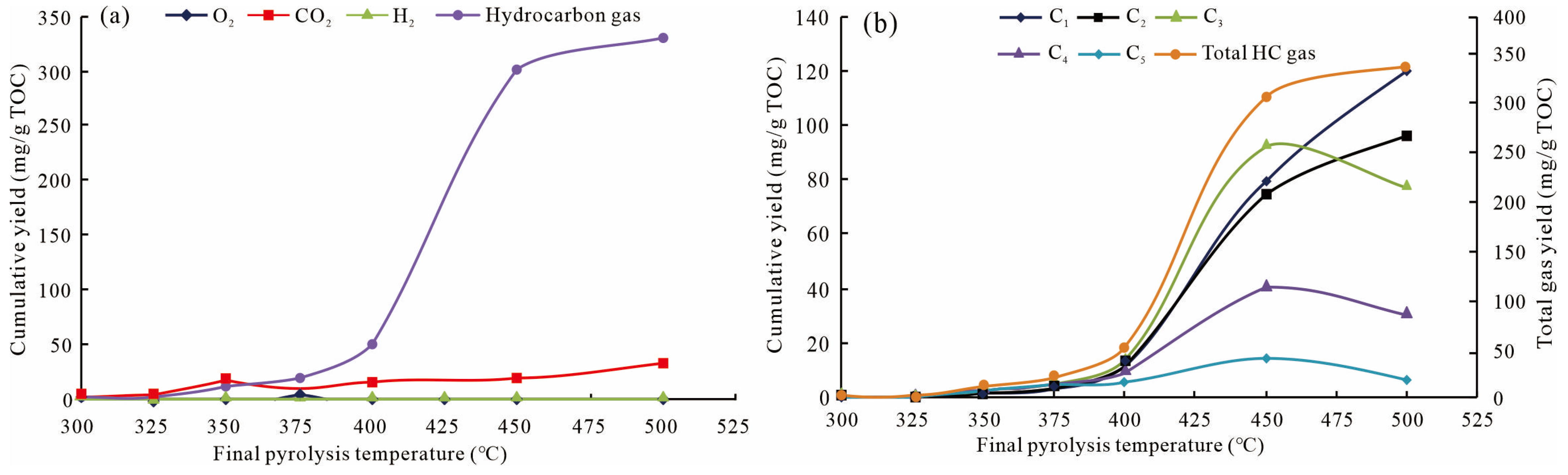
2.3.1. Gas Composition and Quantities

After the experiment, oil, water and gas were separated with the product separation and collection system, in which the gas was collected after entering the metering tube so that we could measure its volume. The gathered pyrolysis gas was qualitatively and semi–quantitatively analyzed with an 6890 gas chromatograph (Agilent, Santa Clara, CA, USA) equipped with a 30 m × 0.32 mm × 20 μm HP–PLOT–Q column and a flame ionization detector (FID). The GC temperature procedure was as follows: hold at 35 °C for 5 min; then, increase to 150 °C at a rate of 5 °C/min; hold for 3 min; and finally, increase to 270 °C at a rate of 10 °C/min. After the system was ready, 1 mL of gas was injected into the gas chromatograph. Methane was used as an external standard gas. Individual gaseous hydrocarbons produced during pyrolysis were quantitatively determined. Non–hydrocarbon gases (N2, H2, CO, and CO2) were analyzed with a MAT 251 high–resolution mass spectrometer (Finnigan, San Jose, CA, USA) and converted into molar concentrations using ideal gas functions [30]. The experimental error was ±0.2%.
A C033 MAT 253 mass spectrometer (Thermo Fisher, Waltham, MA, USA) was used to measure the stable carbon isotope values of hydrocarbon gases according to Chinese standard GB/T 18340.2–2010. The carbon isotope measurement accuracy was estimated to be ±0.2‰ (reported relative to the PDB standard).

2.3.2. Oil (Expelled Oil) and Bitumen (Retained Oil)

During pyrolysis, when the hydrocarbon discharge valve was opened, the expelled oil began to enter the product collection system. After cooling, the oil was collected, weighed, and then quantified with chloroform washing and rotary evaporation. Soxhlet extraction was used to quantify the retained oil or bitumen. First, the solid residue after pyrolysis was dried at 40 °C for 4 h; then, the organic solute was extracted with 200 mL of organic solvent (dichloromethane (DCM): methanol (93: 7 v/v)) in a Soxhlet extraction device for 72 h. The obtained organic residue was placed in a 313.15 K water bath, and solvents were evaporated using a vacuum rotary evaporator. The condensed soluble organic matter was dissolved in n–hexane, and the residual oil in the pyrolyzed shale was obtained by allowing it to settle for 24 h. The analytical error of this method was 5% of the measured weight. Expelled oil and retained oil were called total oil. The terms “retained oil” and “bitumen” were combined to indicate the occurrence state of oil and to also evaluate the fluidity of hydrocarbons.

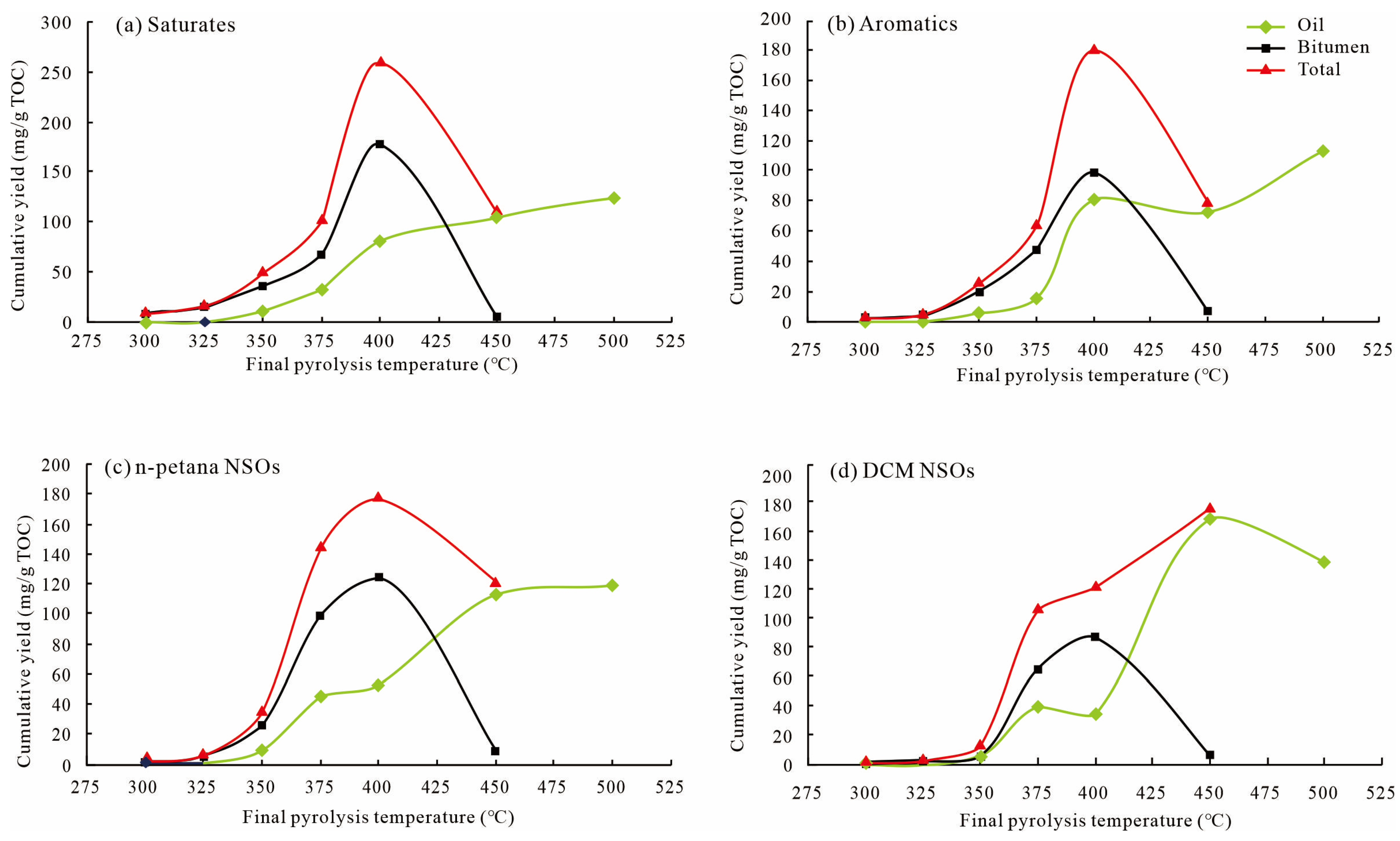
2.3.3. Fractional Composition of Oil and Bitumen

Proper amounts of expelled oil and retained oil were separately placed into beakers. After weighing, we added n–hexane and soaked the samples for 12 h to ensure they were fully dissolved; the solution was filtered with absorbent cotton to obtain asphaltenes (DCM NSOs). The remainder of the solution was separated with silica gel and alumina column chromatography. The chromatographic columns were successively washed with n–hexane, a mixture of dichloromethane and n–hexane (2:1 ratio), and anhydrous ethanol–dichloromethane solution. Saturates, aromatics, and resins (n–pentane NSOs) were obtained, respectively.

3. Results

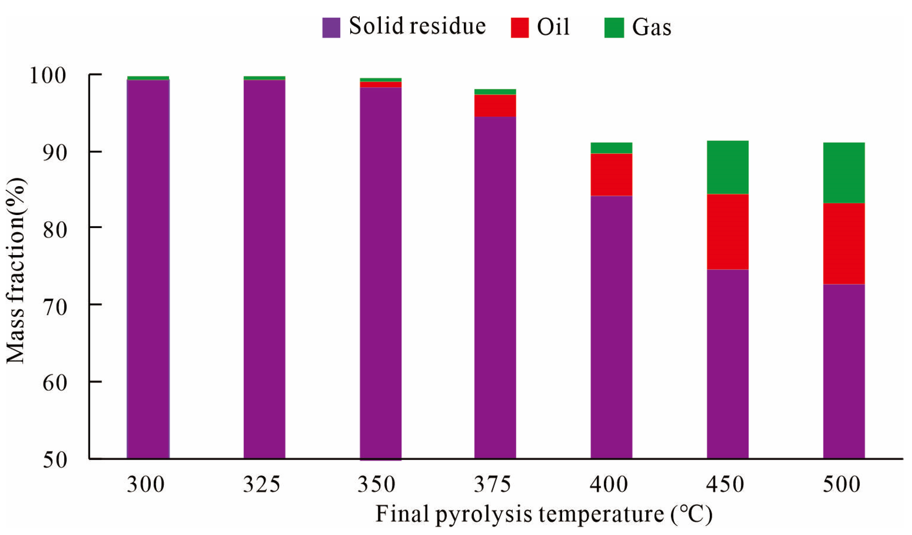
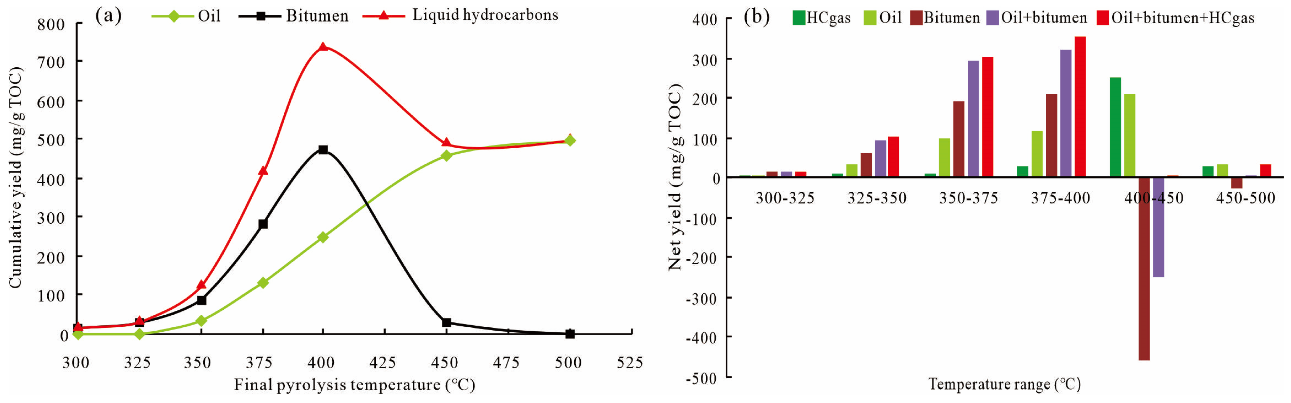
3.1. Overall Mass Balance Calculation

Natural conditions and many types of laboratory experiments involve coupled chemical reactions and mass transport processes. If a chemical process is discussed without considering the mass balance, the model likely fails when applied to natural processes. Throughout the whole reaction process, the products of the source rock heated to a high temperature and under high pressure can be divided into three parts: solid residue, oil, and gas. Theoretically, the combined weight of these three parts should be equal to the weight of the original sample. However, the mass fractions, which were calculated by dividing the mass of products by the mass of the original rock, ranged from 91.0% to 99.4%, that is, lower than 100%. This value slightly decreased with the increase in the pyrolysis temperature (Figure 4).
By analyzing the experimental device and product collection process, it is believed that the reasons for this result were the following: (1) During kerogen cracking, water was generated, which could not be weighed or measured; thus, it was not included in the weight of liquid products in our experiments, resulting in mass loss. (2) In the product separation and collection system, although freezing measures were adopted to prevent the loss of light hydrocarbon components (C6–C14), losses were still inevitable during oil concentration and transfer; the lower mass fraction at higher temperatures was due to the loss of this fraction. (3) At the end of the experiment, a small part of the solid residue remained in the filter screen of the instrument and could not be recovered. In addition to these force majeure factors, from the results of the mass fraction and its relative error, it can be considered that the experiment was still reliable.

3.2. Yields of Liquid Hydrocarbons

Each experiment was conducted from room temperature to the terminal temperature, and the products were the total amounts collected during the process. Therefore, the yields of gas, oil, and bitumen were the cumulative yields. The net increment between two adjacent temperatures was the result of the subtraction of one cumulative product from the other. This was used to indicate the relationship between product yield and consumption within a specific temperature range or maturity range.
Due to the generation of oil and gases during the experiment, the pressure of the system increased. When the boundary conditions were reached, the valve automatically opened to expel hydrocarbons; vice versa, when the pressure dropped below the set conditions, the valve was re–closed until the pressure exceeded the set value once again. With this design, the device overcame the shortcomings of open systems and closed systems, which allowed it to simulate the secondary cracking episodic hydrocarbon expulsion process of source rock under actual geological conditions.
The overall characteristics of the liquid hydrocarbons are shown in Table 3 and Figure 5. The cumulative yield of liquid hydrocarbons and bitumen first increased and then decreased, reaching the peak values of 720.42 mg/g TOC and 472.09 mg/g TOC at 400 °C, respectively. The cumulative yield of oil always increased, because it was expelled from the reactor without experiencing secondary cracking. It was low and stable at 300–325 °C, averaging 0.81 mg/g TOC, and began to rise sharply at 350 °C. The increase rate began to slow down at 450 °C, reaching 459.51 mg/g TOC. The cumulative yield of bitumen and oil intersected at 420 °C, and the yield of bitumen was always higher than that of oil below 420 °C; then, the trend reversed.
The saturate, aromatic, resin, and asphaltine (SARA) yield changes in oil and bitumen are shown in Table 3 and Figure 6. The cumulative yields of saturates and aromatics in the oil increased from 0.29 to 124.74 mg/g TOC and from 0.06 to 112.81 mg/g TOC, respectively. The total yields of n–pentana NSOs (resins) and DCM NSOs (asphaltenes) increased between 300 and 450 °C and reached the peak of 283.2 mg/g TOC at 450 °C, before beginning to decline to 258.73 mg/g TOC at 500 °C. In bitumen, all components displayed arc–shaped trends with an inflection point at 400 °C. The maximum yields of saturates, aromatics, and NSOs were 171.75 mg/g TOC, 95.37 mg/g TOC, and 204.97 mg/g TOC, respectively.

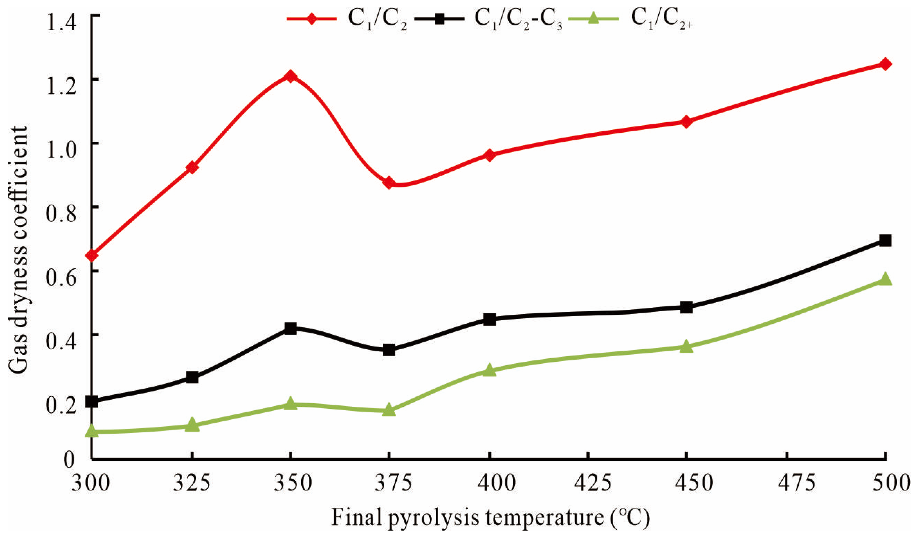
3.3. Product Yields of Gas

The gas composition included hydrocarbon gases (C1–C5) and non–hydrocarbon gases (CO2, H2, and O2). Non–hydrocarbon gases generally maintained a stable trend, with an average of 16.19 mg/g TOC (Figure 7a). Below 350 °C, non–hydrocarbon products accounted for 55–81% of the total gaseous product volume, especially CO2. The phenomenon whereby the proportion of non–hydrocarbon gases is greater than that of hydrocarbon gases in the initial stage of pyrolysis has been observed in thermal simulation experiments [31]. Above 350 °C, the cumulative yield of hydrocarbon gases began to exceed that of non–hydrocarbon gases, and the proportion of hydrocarbon gases to the total gases continued to rise.
Table 4 and Figure 7b show the compositional characteristics of hydrocarbon gases (all yields were converted to mg/g TOC). With the increase in the pyrolysis temperature, the hydrocarbon gases showed a three–stage increase. At 300–375 °C, the cumulative yield of hydrocarbon gases slowly rose from 1.28 to 19.46 mg/g TOC and then showed a sharp increase at 375–450 °C from 19.46 to 300.45 mg/g TOC. The growth rate slowed at 450–500 °C from 300.45 to 330.35 mg/g TOC. For each component, increasing the pyrolysis temperature increased the cumulative yields of methane (CH4) and ethane (C2H6), reaching a peak at 500 °C, with 120.27 and 96.09 mg/g TOC, respectively. The difference is that the yield of methane rose faster at 450 °C, while the yield of ethane slowed down. The yields of propane–pentane (C3–C5) first increased and then decreased, reaching peaks of 91.9, 40.2, and 14.4 mg/g TOC at 400 °C, respectively. Three indicators of gas dryness were calculated: C1/C2+, C1/C2, and C1/C2–C3. It can be seen in Figure 8 that these three indicators showed similar trends: an increase at 300–350°C, a decrease at 350–375 °C, and then a continuous increase, especially at 450 °C, whose rising speed was faster (Figure 8).
The carbon isotope composition of natural gas is an important parameter for studying the geochemical characteristics of natural gas. Table 4 and Figure 9 show that the distribution ranges of δ13C1, δ13C2, δ13C3, δ13C4, and δ13C5 were −45.4% to −37.3%, −38.6‰ to −28.9‰, −35.5‰ to −23.8 ‰, −34.55‰ to −22.1‰, and −33.1‰ to −19.15‰, respectively. The isotope value of methane was higher than that of ethane below 320 °C, but the isotope composition of hydrocarbon gases at other temperatures obeyed the normal carbon isotope sequence, i.e., δ13C1 < δ13C2 < δ13C3 < δ13C4 < δ13C5. With the increase in the temperature, the carbon isotope of hydrocarbon gases first decreased and then increased; in particular, the trend of methane change was the most significant. The non–monotonic change in the δ13C1 value may indicate that there were multiple sources of early CH4 [32,33].

4. Discussion

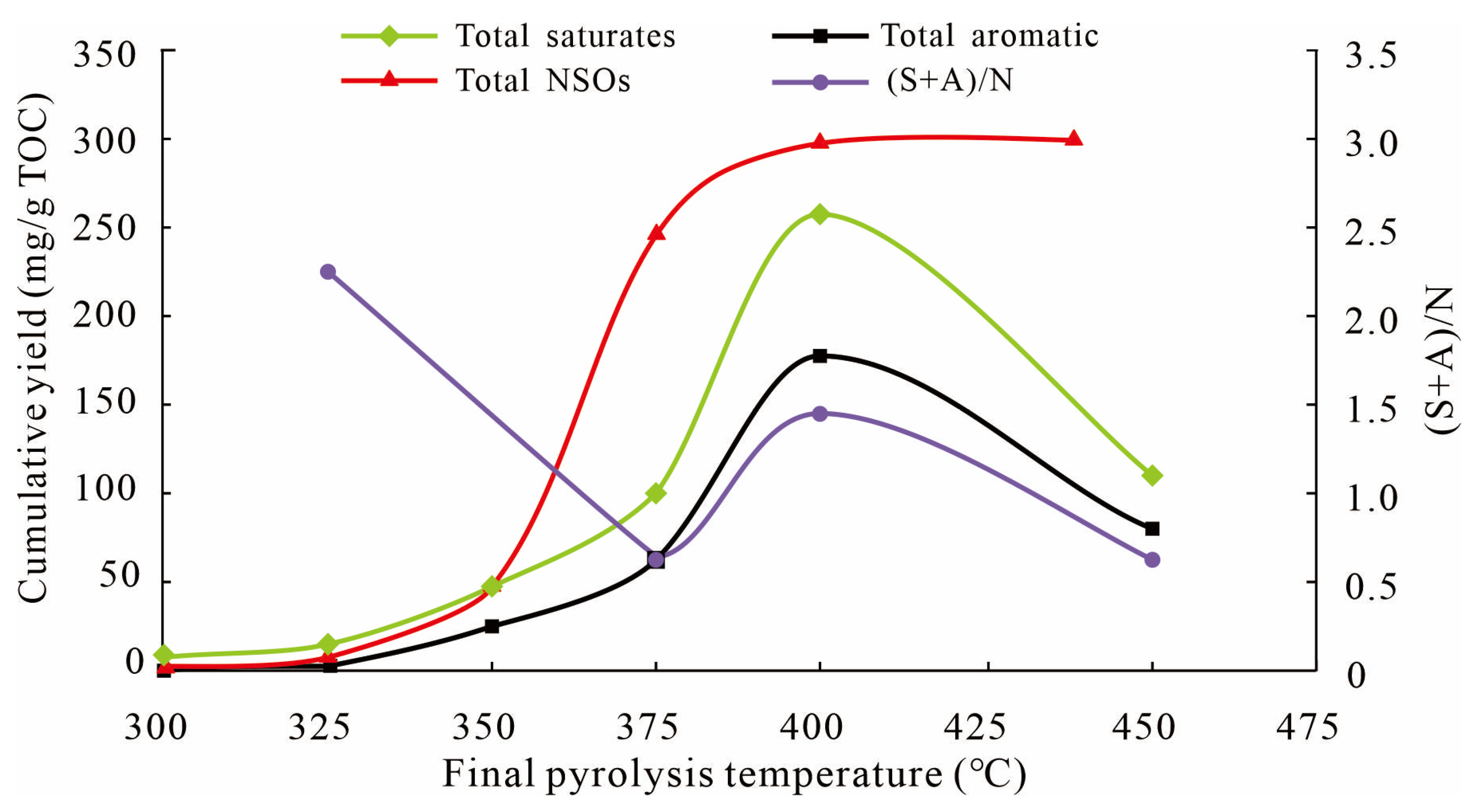
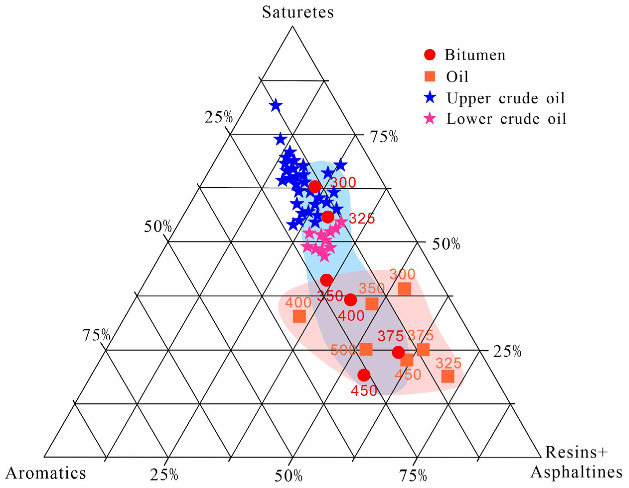
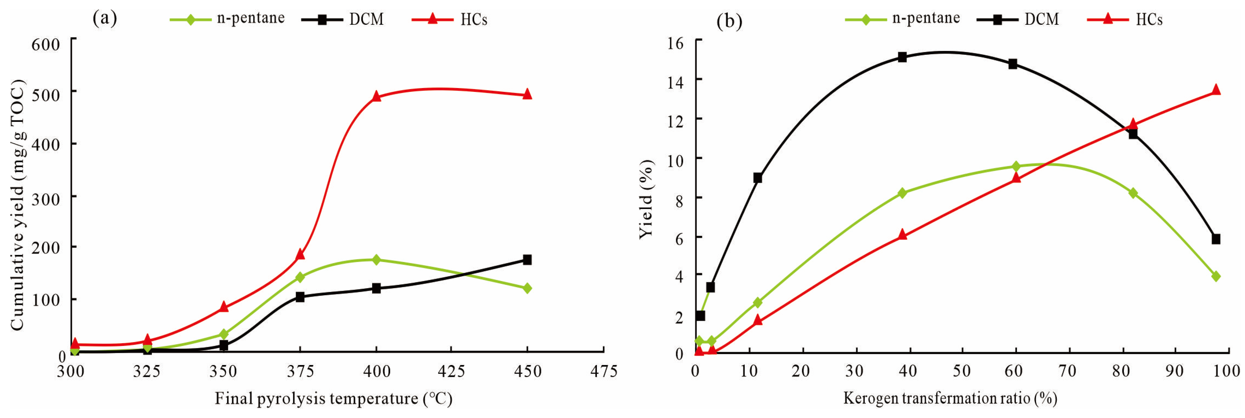
4.1. Characteristics of Liquid Hydrocarbon Generation, Expulsion, and Retention

At 300–325 °C, the shale displayed low thermal maturity. Kerogen decomposition simultaneously produces oil and bitumen. Although the bitumen yield was higher than that of oil, there were no changes in the order of magnitude (Figure 5), which indicated a different behavior from that of type I organic matter of Green River shale and Batateria Beds shale in thermal simulation experiments. At 325–350 °C, kerogen rapidly decomposed and produced greater yields of bitumen and oil. The slope of the heavy components (NSOs) of total oil was greater than that of volatile components (saturates + aromatics) (Figure 6). In addition, the ratio of saturates and aromatics to NSOs ((S + A)/N)) continued to decrease (Figure 10). These results indicate that kerogen generated more high–molecular–weight bitumen than low–molecular–weight oil. At 350–400 °C, kerogen generated large amounts of liquid hydrocarbons and reached the most intensive stage at 400 °C. The temperature of 350 °C might be considered the onset of bitumen cracking, as the net yield of oil started to increase smoothly with no break slope (Figure 5b). The inflection point of (S + A)/N at 375 °C might indicate that bitumen entered the intensive cracking stage to generate low–molecular–weight oil, resulting in better oil quality (Figure 10). At 400–450 °C, affected by the gradual reduction in the hydrocarbon generation potential of kerogen, the cracking rate of bitumen exceeded its generation rate, resulting in the decrease in its net yield (Figure 5b). In contrast, the cumulative yield of oil continued to increase, and this trend was unaffected by the decline in bitumen, indicating that this part of oil was supposedly originated from the secondary cracking of bitumen rather than kerogen. At the same time, liquid hydrocarbons began to undergo secondary cracking, and saturates and aromatics began to desorb aliphatic group C–Hx bonds and decreased (Figure 10) [34,35], forming hydrocarbon gases with a high H/C atomic ratio.
The overall fractionation characteristics of SARAs are shown in Figure 11. Both oil and bitumen shared the same SARA components. In the low–temperature simulation pyrolysis stage (300 °C and 325 °C), there was a clear separation with no overlap between oil and bitumen. This separation vanished at high temperatures. Interestingly, the ternary diagram shows that the SARA percentages of bitumen in our experiment matched those of natural crude oil, and bitumen was more enriched with saturates than the corresponding oil. This is consistent with the previous accumulation model of Lucaogou Formation, which is referred to as “self–generation and self–preservation” [36,37,38]. The results of our experiment do not support the rule of preferential discharge of light hydrocarbon components [39,40]. We compared the experimental process and hydrocarbon generation process and believe that the reasons for the differences are as follows: (1) During the experiment, we set the confining pressure and hydrocarbon expulsion pressure to values that will increase upon increasingthe pyrolysis temperature, which inhibited the fractionation and expulsion of hydrocarbon components. (2) The sample selected for our research had a high organic carbon content. According to the principle of similarity and compatibility, the light components could be easily blended with heavy components. This shows that the higher the TOC of shale is, the higher its retention content is [41,42].
The limit of bitumen (retained oil) and oil (expelled oil) in this part was not defined by whether they could be recovered, but rather by whether they could be discharged from the system under the current set pressure. Both can be commercially recovered under certain conditions.

4.2. Kerogen Decomposition Process and Oil Generation Mechanism

The hydrocarbon generation process of kerogen is complex. At present, it is believed that there are two different mechanisms by which kerogen generates oil and gas. One is the sequential hydrocarbon generation model, whereby kerogen first generates macromolecular NSOs and these are then cracked into smaller hydrocarbons. Behar et al. [44,45] conducted kerogen pyrolysis experiments under closed pyrolysis conditions and verified this mechanism. In Behar’s research on Toarcian shale (type II), the components of oil and bitumen were divided into volatile components (saturates and aromatics) and heavy components (NSOs), and NSOs were further divided into n–pentane NSOS (resins) and DCM NSOs (asphaltenes) according to their solubility in organic solvents. The total hydrocarbons (HCs) included hydrocarbon gases (C1–C5), saturates, and aromatic components in bitumen and oil. The research results showed that in the initial stage of thermal simulation of Toarcian shale, DCM NSOs were produced in large quantities at the beginning of pyrolysis and quickly reached their peak. The total hydrocarbon yield also increased with kerogen conversion. However, before reaching the conversion rate of 80%, the HC yield was far less than the total amount of DCM NSOs and n–pentane NSOs (Figure 12b).
Another “alternative pathway” mechanism was proposed by Burnham et al. [46], whose results showed that kerogen simultaneously generated NSOs and HCs, without strict boundaries. In terms of chemical structure, kerogen is a polymer, a macromolecular mixture composed of a cross–linked core structure and side chains connected to the core [47,48]. The essence of kerogen cracking is the breaking of chemical bonds, following the principle that weaker bonds break before stronger bonds. Before the large–scale breaking of the chemical bonds of macromolecular kerogen (corresponding to the secondary cracking stage), the formation of NSOs was caused by the breaking of weak cross–links among kerogen molecules. HCs were caused by main–chain breakage or the loss of aliphatic branches in kerogen [49]. It is generally believed that the bond dissociation energy (BDE) of the branched chain of aliphatic functional groups is less than that of the long main chain. If the structure of the branch chain is more complex and one hydrogen in the methyl is replaced by the methylene structure of the other branch chain, the bond dissociation energy is weaker and is approximately equal to the cross–link [50,51,52]. As kerogen contains enough branches, it is possible that during the initial stage of cleavage, cross–links were broken to produce NSOs and the branched–chain broke to simultaneously produce HCs.
Our results show that the initial pyrolysis products were dominated by HCs, and their yields were higher than those of DCM NSOs and n–pentane NSOs. In all experiments, the total hydrocarbon yield was always higher than that of NSOs (Figure 12a). This indicates that hydrocarbon generation from kerogen and NSOs occurred synchronously during the initial stage of pyrolysis. According to the model by Burnham et al. [53], we plotted the distribution of chemical components in oil and bitumen as a function of the temperature (Figure 13). The results are consistent with Burnham’s, according to whom the proportions of C15+sat, C15+aro, and NSOs in oil and bitumen showed an overall increase and were unaffected by fluctuations in oil and bitumen yields.
In conclusion, the reaction process of Lucaogou type I shale was more consistent with the “alternative pathway” mechanism, and the formation of HCs and NSOs was controlled by independent bond–breaking reactions. Lacustrine Chang 7 shale (type II) also showed the same kerogen decomposition mechanism [54]. This differed from that of marine shale and was attributed to the stark difference in the depositional environment and the origin of organic matter in a saline–alkali lacustrine environment [55]. From the perspective of the chemical structure of kerogen, this special reaction pathway may indicate that there are abundant weak BDE aliphatic branched chains in the kerogen of shale from Lucaogou Formation. Although the results of the study accurately simulate the site conditions, further studies (e.g., FT–IR and 13C NMR) are needed to have a better understanding of the changes in kerogen structure during the thermal evolution process. Our research results still support this conclusion from the perspective of hydrocarbon generation.
Although we believe that the formation of HCs and NSOs in shale from Lucaogou Formation occurred via the “alternative pathway”, the experimental results do not deny the fact that NSOs can generate HCs. It can be seen that the yield of HCs showed an extremely steep increase at 375 °C, which may have been caused by the superposition of the initial cracking of kerogen and the secondary cracking of NSOs, and at 400 °C, the hydrocarbon generation potential of kerogen gradually decreased, while large amounts of HCs were still generated (Figure 5). Therefore, there was no contradiction between the generation of HCs from kerogen cracking and the generation of HCs from NSO cracking in different stages. However, this requires an analysis of the specific situation to determine which role was dominant.

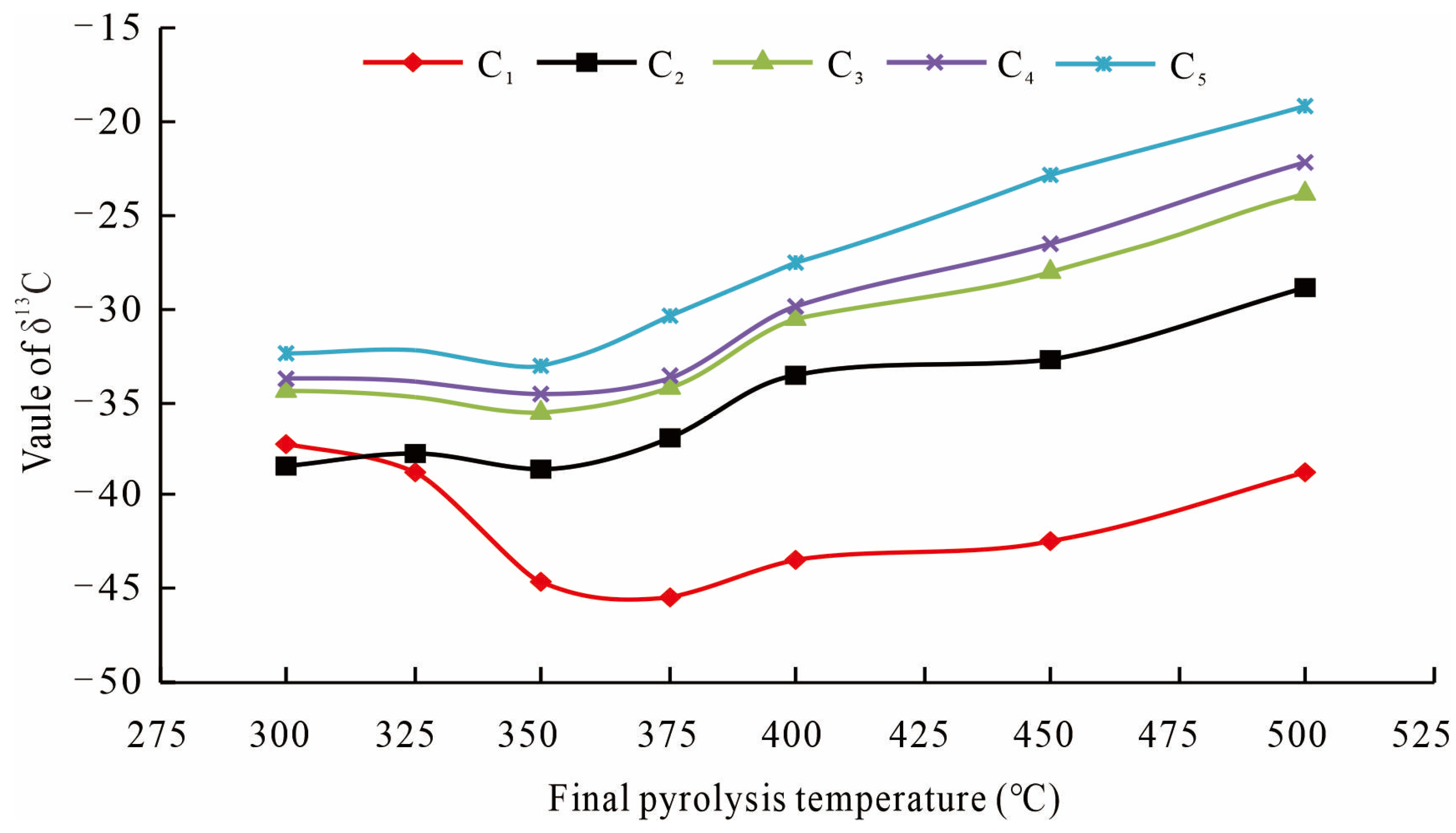
4.3. Implications for Shale Gas Genesis

In non–hydrocarbon gases, the CO2 yield accounted for the majority, followed by H2 and O2. H2S was not detected. Since kerogens, partially marine kerogen I and, in some cases, terrestrial type III kerogens, contain oxygen–bearing functional groups [56,57,58,59], a large amount of CO2 gas produced during the initial stage of pyrolysis is determined by the structure of kerogen. Previous studies on the activation energy among the different atoms of kerogen showed that the carboxyl and carbonyl groups of kerogen are easily broken due to the low bond dissociation energy (BDE) of C–O/C=O bonds compared with C–C bonds and produce oxygen–containing substances such as CO2, H2O, and NSOs in the initial pyrolysis stage [60,61]. However, almost no CO2 was found in the oil and gas system. This was because CO2 is highly soluble in groundwater, reacts with calcium in the water of carrier beds, and forms carbonate cement [62]. Secondary carbonate minerals with a low δ13C value in Lucaogou shale indicate the occurrence of this process [63].
There are three mechanisms for hydrocarbon generation during thermal maturation: kerogen decomposition, the secondary cracking of oil, and the secondary cracking of wet gas [64]. According to different mechanisms, the generation of hydrocarbon gases from Lucaogou shale can be divided into four stages: At 300–350 °C, kerogen mainly cracked to produce methane. In this stage, the yield of methane was the highest among hydrocarbon gases, with a yield roughly equal to the total yield of C2–C5. The dryness coefficient of gas increased with the increase in the temperature. At the same time, due to kerogen having no isotopic fracture, so δ13C was enriched, resulting in a relatively high–carbon isotope of methane in this stage (Figure 9). At 350–375 °C, the oil began to undergo secondary cracking and produce wet gas, resulting in the reduction in the dryness coefficient, but from the perspective of yield, the degree of oil cracking in this stage was limited (Figure 5). The δ13C of hydrocarbon gases remained relatively stable. At 375–450 °C, crude oil cracking produced a large amount of wet gas. At the same time, due to oil being gradually enriched with δ13C, it became the main source of hydrocarbon gas, resulting in the δ13C of hydrocarbon gases gradually increasing (Figure 9). At 450–500 °C, wet gas started the process of secondary cracking to produce methane, resulting in the yields of C3 and C5 beginning to decline, and the methane yields began to exceed the wet gas yields (Figure 7b). The dryness coefficient greatly increased. Due to the δ13C value of wet gas being greater than that of oil in terms of isotopic fractionation, the δ13C1 growth rate began to increase (Figure 9). The secondary cracking process of hydrocarbon gases has been revealed in many previous experiments [65,66,67]. During the secondary cracking of oil, high–molecular–weight hydrocarbon gases are preferentially generated and are also preferentially broken to generate small–molecule hydrocarbon gases due to their weak thermal instability. Finally, all hydrocarbon gases are converted to methane (CH4) with greater thermal stability.
The gas–to–oil ratio (GOR; reported in m3/m3) of each parallel experiment was calculated. The volume of hydrocarbon gases was measured during the experiment, while the volume of oil was obtained by dividing the average density (0.83 g/cm3) of oil by its weight. The density data were obtained from Cao et al. [43]. The changes in the GOR with the increase in the pyrolysis temperature are shown in Figure 14. With the increase in the pyrolysis temperature, the GOR first decreased and then increased. The initially curvilinear decrease observed by Lewan and Henry [68] also occurred in our study. The high GOR values at 300–325 °C were due to the high yield of gas (especially CH4) compared with that of oil. When bitumen entered the intense cracking period, the oil yield increased, but the secondary cracking of oil had not begun, causing the GOR to decrease. Above 375 °C, due to the gas generated by the large–scale cracking of crude oil, the GOR began to sharply rise, reaching 489 m3/m3 at 500 °C.

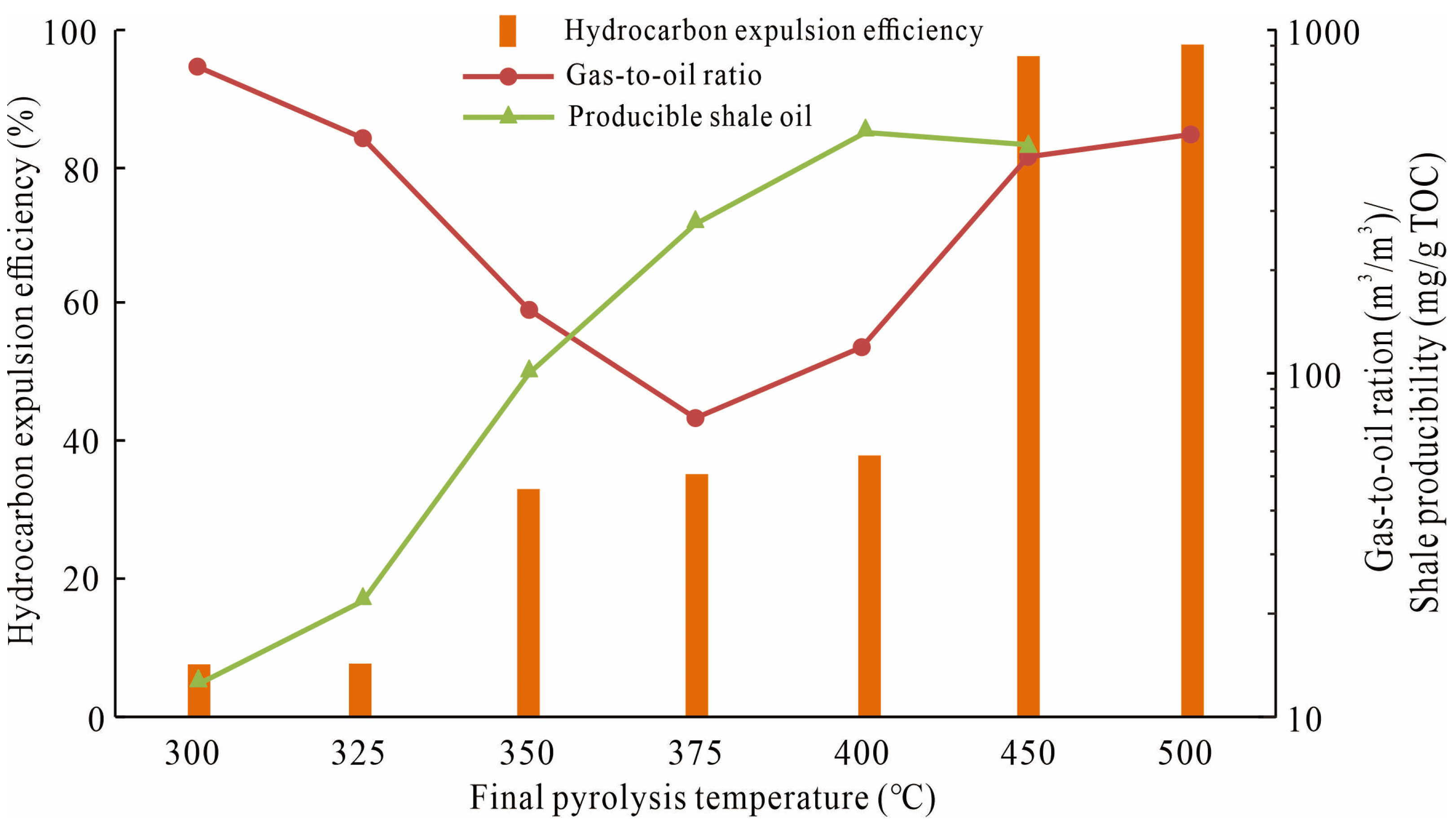
4.4. Hydrocarbon Expulsion Efficiency and Producible Shale Oil Assessment

The hydrocarbon expulsion efficiency (HEE) of Lucaogou Formation shale was calculated according to previous research results [69]. The HEE is defined as the ratio of expelled hydrocarbons to the total generated hydrocarbons:
HEE = Expelled   hydrocarbon Total   hydrocarbon = Expelled   oil + Expelled   gas Expelled   oil + Expelled   gas + Bitumen ,
where the expelled gas only includes hydrocarbon gas and the unit of all products is mg/g TOC.
Changes in the hydrocarbon expulsion efficiency (HEE) during pyrolysis are shown in Figure 14. Before reaching the peak oil production period (400 °C), the HEE of shale was low, averaging 27%, indicating that most of the generated oil was retained in shale. After reaching peak oil generation, due to the generation of gas and light oil caused by the cracking of oil, the flowability of oil was improved, resulting in a sudden rise in the HEE to 97%. Most of the generated hydrocarbons could be discharged. The evolution trend of the HEE during the experiment is consistent with the results of Bai et al. [70] and Zhou et al. [71], who used the rock pyrolysis method to calculate the hydrocarbon expulsion efficiency of Lucaogou Formation shale.
An accurate evaluation of the oil in place (OIP) of a shale reservoir is an important indicator during oilfield development. Current evaluation methods include physical rock modeling, oil charging system modeling, and directly measuring rock samples [72]. Dynamic changes in the OIP were directly measured in our study. Though we define retained oil as the fraction that cannot be expelled from shale, when horizontal and hydraulic fracturing mining methods are used [73], some of the retained oil can be eventually produced. A previous study showed that aromatics and saturates were more easily expelled than other components [74]. Therefore, the producible oil in our study was defined as the sum of expelled oil and the saturates and aromatics in retained oil (all are reported in mg/g TOC).
The yield of producible oil showed an arched evolution trend, reaching the maximum value of 512.46 mg/g TOC at 400 °C (Figure 14). This temperature corresponded to the maximum yield of total liquid hydrocarbons (Figure 5a) and was also the temperature at which the “(S + A)/N” ratio reached a relatively high value (Figure 10). The phenomenon of different trends of producible oil or total liquid hydrocarbons with HEE showed that Lucaogou Formation is characterized by early generation but a low HEE value. This was due to the notable influence of kerogen expansion and the adsorption of organic matter [75,76]. Below 400 °C, the generated hydrocarbons could not fill the adsorption sites, or the flowability of hydrocarbons was low, causing them to become trapped in the system. In addition, due to the generation of hydrocarbons, the volume of organic matter decreased, forming micro– and nanopores [77,78,79], which provided storage space for oil, as well as a greater surface area to adsorb more oil. The above analysis indicates that 400 °C is considered the most suitable temperature for fracturing technology.

5. Conclusions

Based on organic–rich mixed siliciclastic–carbonate shale from Lucaogou Formation, this study establishes a hydrocarbon generation–retention–expulsion model, reveals the hydrocarbon generation mechanism, and ultimately predicts the in situ oil recovery of shale at different pyrolysis temperatures:
(1)
The hydrocarbon generation stage of mixed siliciclastic–carbonate shale from Lucaogou Formation can be divided into the kerogen cracking stage (300–350 °C), the peak oil generation stage (350–400 °C), the wet gas generation stage (400–450 °C), and the hydrocarbon gas secondary cracking stage (450–500 °C). The liquid hydrocarbon yield (oil + bitumen) reached at a peak of 720.42 mg/g TOC at 400 °C.
(2)
Oil and bitumen shared the same group fractions, but there was a clear separation with no overlap between oil and bitumen in the initial stage of pyrolysis (300 and 325 °C). The group fractions of bitumen overlapped with those of crude oil from the upper section of Lucaogou Formation, and bitumen was more enriched with saturates than their corresponding oil. These results support the reservoir–forming model of “self–generation and self–preservation” of the shale of Lucaogou Formation. It also shows that the semi–closed hydrous thermal simulation experiment could reliably simulate the hydrocarbon generation process for site conditions.
(3)
In the initial stage of pyrolysis (300–350 °C), due to the joint adsorption of shale organic matter and pores, the hydrocarbon expulsion efficiency of shale was relatively low, with an average of 13%. The source rock reached the hydrocarbon explosion threshold (average HEE = 36%) at 350–400 °C and then rose sharply to 97% at 450 °C. These results mean that considerable amounts of oil cannot be discharged from shale until the temperature reaches 450 °C.
(4)
The producible oil was positively correlated with total liquid hydrocarbons, showing an arched evolution trend with the increase in the pyrolysis temperature and reaching a maximum of 512.46 mg/g TOC at 400 °C. After comprehensive consideration of the generated yield and hydrocarbon expulsion efficiency. Therefor, 400 °C is considered to be the most suitable temperature for fracturing technology.

Author Contributions

J.W., Writing—original draft; J.T., Supervision, Funding acquisition, and Writing—review and editing; J.J., Supervision; J.L., Investigation, and Validation; L.C., Writing—review and editing; H.C., Investigation; X.M., Investigation; X.S., Software. All authors have read and agreed to the published version of the manuscript.

Funding

This study was supported by Fundamental Research Funds for the Central Universities of Central South University (Grant No. 2022ZZTS0531) and China Hunan Provincial Science & Technology Department (Grant No. 2022WK2004).

Data Availability Statement

No new data were created or analyzed in this study.

Acknowledgments

We thank Ma Zhongliang, a researcher from Sinopec Wuxi Research Institute of Petroleum Geology, for his guidance in the thermal simulation experiments.

Conflicts of Interest

The authors declare no conflict of interest.

References

  1. Lei, Y.; Zhijun, J.I.N. Global shale oil development and prospects. China Pet. Explor. 2019, 24, 553. [Google Scholar]
  2. Zou, C.; Yang, Z.; Cui, J.; Zhu, R.; Hou, L.; Tao, S.; Yuan, X.; Wu, S.; Lin, S.; Wang, L.; et al. Formation mechanism, geological characteristics and development strategy of nonmarine shale oil in China. Petrol. Explor. Dev. 2013, 40, 15–27. [Google Scholar] [CrossRef]
  3. Zhao, W.; Hu, S.; Hou, L.; Tao, Y.; Li, X.; Guo, B.; Yang, Z. Types and resource potential of continental shale oil in China and its boundary with tight oil. Pet. Explor. Dev. 2020, 47, 1–11. [Google Scholar] [CrossRef]
  4. Shao, X.H.; Pang, X.Q.; Li, M.W.; Li, Z.M.; Zhao, Y. Hydrocarbon generation from lacustrine shales with retained oil during thermal maturation. Pet. Sci. 2020, 17, 1478–1490. [Google Scholar] [CrossRef]
  5. Hill, R.J.; Zhang, E.; Katz, B.J.; Tang, Y. Modeling of gas generation from the Barnett shale, Fort Worth Basin, Texas. AAPG Bull. 2007, 91, 501–521. [Google Scholar] [CrossRef]
  6. Ritter, U. Fractionation of petroleum during expulsion from kerogen. J. Geochem. Explor. 2003, 78, 417–420. [Google Scholar] [CrossRef]
  7. Li, T.; Jiang, Z.; Xu, C.; Liu, B.; Liu, G.; Wang, P.; Li, X.; Chen, W.; Ning, C.; Wang, Z. Effect of pore structure on shale oil accumulation in the lower third member of the Shahejie formation, Zhanhua Sag, eastern China: Evidence from gas adsorption and nuclear magnetic resonance. Mar. Pet. Geol. 2017, 88, 932–949. [Google Scholar] [CrossRef]
  8. Sun, L.; He, W.; Feng, Z.; Zeng, H.; Jiang, H.; Pan, Z. Shale Oil and Gas Generation Process and Pore Fracture System Evolution Mechanisms of the Continental Gulong Shale, Songliao Basin, China. Energy Fuels 2022, 36, 6893–6905. [Google Scholar] [CrossRef]
  9. Seewald, J.S. Aqueous geochemistry of low molecular weight hydrocarbons at elevated temperatures and pressures: Constraints from mineral buffered laboratory experiments. Geochim. Et Cosmochim. Acta 2001, 65, 1641–1664. [Google Scholar] [CrossRef]
  10. Seewald, J.S. Organic–inorganic interactions in petroleum–producing sedimentary basins. Nature 2003, 426, 327–333. [Google Scholar] [CrossRef]
  11. Pan, C.; Jiang, L.; Liu, J.; Zhang, S.; Zhu, G. The effects of calcite and montmorillonite on oil cracking in confined pyrolysis Experiments. Org. Geochem. 2010, 41, 611–626. [Google Scholar] [CrossRef]
  12. Xi, K.; Cao, Y.C.; Zhu, R.K.; Shao, Y.; Xue, X.; Wang, X.; Gao, Y.; Zhang, J. Rock types and characteristics of tight oil reservoir in Permian Lucaogou Formation, Jimusaer sag. Acta Petrol. Sin. 2015, 36, 1495–1507, (In Chinese with English abstract). [Google Scholar]
  13. Wu, H.; Hu, W.; Cao, J.; Wang, X.; Wang, X.; Liao, Z. A unique lacustrine mixed dolomitic–clastic sequence for tight oil reservoir within the middle Permian Lucaogou Formation of the Junggar Basin, NW China: Reservoir characteristics and origin. Mar. Pet. Geol. 2016, 76, 115–132. [Google Scholar] [CrossRef]
  14. Zhang, J.; Liu, G.; Cao, Z.; Tao, S.; Felix, M.; Kong, Y.; Zhang, Y. Characteristics and formation mechanism of multi–source mixed sedimentary rocks in a saline lake, a case study of the Permian Lucaogou Formation in the Jimusaer Sag, northwest China. Mar. Pet. Geol. 2019, 102, 704–724. [Google Scholar] [CrossRef]
  15. Wang, Y.; Cao, J.; Tao, K.; Li, E.; Ma, C.; Shi, C. Reevaluating the source and accumulation of tight oil in the middle Permian Lucaogou Formation of the Junggar Basin, China. Mar. Pet. Geol. 2020, 117, 104384. [Google Scholar] [CrossRef]
  16. You, J.; Lee, K.J. The experimental investigation and data–driven modeling for thermal decomposition kinetics of Green River Shale. Fuel 2022, 320, 123899. [Google Scholar] [CrossRef]
  17. Kuang, W.; Lu, M.; Yeboah, I.; Qian, G.; Duan, X.; Yang, J. A comprehensive kinetics study on non–isothermal pyrolysis of kerogen from green river oil shale. Chem. Eng. J. 2018, 377, 120275. [Google Scholar] [CrossRef]
  18. Hillier, J.L.; Fletcher, T.H.; Solum, M.S.; Pugmire, R.J. Characterization of macromolecular structure of pyrolysis products from a Colorado Green River oil shale. Ind. Eng. Chem. Res. 2013, 52, 15522–15532. [Google Scholar] [CrossRef]
  19. Le Doan, T.V.; Bostrom, N.W.; Burnham, A.K.; Kleinberg, R.L.; Pomerantz, A.E.; Allix, P. Green River oil shale pyrolysis: Semi–open conditions. Energy Fuels 2013, 27, 6447–6459. [Google Scholar] [CrossRef]
  20. Burnham, A.K. Kinetic models of vitrinite, kerogen, and bitumen reflectance. Org. Geochem. 2019, 131, 50–59. [Google Scholar] [CrossRef]
  21. Lewan, M.D.; Roy, S. Role of water in hydrocarbon generation from Type–I kerogen in Mahogany oil shale of the Green River Formation. Org. Geochem. 2011, 42, 31–41. [Google Scholar] [CrossRef]
  22. Bohacs, K.M.; Carroll, A.R.; Neal, J.E.; Mankiewicz, P.J. Lake–basin type, sourcepotential, and hydrocarbon character: An integrated–sequence–stratigraphice geochemical framework. In Aapg Studies in Geology; Lake Basins Through Space and Time; Gierlowski–Kordesch, E.H., Kelts, K.R., Eds.; AAPG: Tulsa, OK, USA, 2000; Volume 46, p. 3e34. [Google Scholar]
  23. Burnett, A.P.; Soreghan, M.J.; Scholz, C.A.; Brown, E.T. Tropical East African climate change and its relation to global climate: A record from Lake Tanganyika, tropical East Africa, over the past 90þ kyr. Palaeogeogr. Palaeoclimatol. Palaeoecol. 2011, 303, 155e167. [Google Scholar] [CrossRef]
  24. Spigolon, A.L.; Lewan, M.D.; De Barros Penteado, H.L.; Coutinho, L.F.C.; Mendonça Filho, J.G. Evaluation of the petroleum composition and quality with increasing thermal maturity as simulated by hydrous pyrolysis: A case study using a Brazilian source rock with Type I kerogen. Org. Geochem. 2015, 83, 27–53. [Google Scholar] [CrossRef]
  25. Korkmaz, S.; Kara–G€ulbay, R.; Iztan, Y.H. Organicgeochemistry of the Lower Cretaceous black shales and oilseep in the Sinop Basin, northern Turkey: An oil–sourcerock correlation study. Mar. Pet. Geol. 2013, 43, 272–283. [Google Scholar] [CrossRef]
  26. Ma, Z.; Tan, J.; Zheng, L.; Shen, B.; Wang, Z.; Shahzad, A. Evaluating gas generation and preservation of the Wufeng–Longmaxi Formation shale in southeastern Sichuan Basin, China: Implications from semiclosed hydrous pyrolysis. Mar. Pet. Geol. 2021, 129, 105102. [Google Scholar] [CrossRef]
  27. Ma, Z.; Zheng, L.; Xu, X.; Bao, F.; Yu, X. Thermal simulation experiment of organic matter–rich shale and implication for organic pore formation and evolution. Pet. Res. 2017, 2, 347–354. [Google Scholar] [CrossRef]
  28. Fang, S.; Xu, H.; Song, Y.; Li, J.; Liu, L.; Zhang, J. Characteristics and evolution of the composite petroleum system in Jimsar Depression, eastern Junggar Basin. Acta Geosci. Sin. 2005, 26, 259–264, (In Chinese with English abstract). [Google Scholar]
  29. Qiu, N.; Yang, H.; Wang, X. Tectonothermal evolution in the Junggar Basin. Chin. J. Geol. 2002, 37, 423–429, (In Chinese with English abstract). [Google Scholar]
  30. Wu, Y.; Zhang, Z.; Sun, L.; Li, Y.; He, C.; Ji, L.; Su, L.; Zhang, D. Hydrocarbon generation and potential in continental organic–rich shales at the highly–mature stage, as determined by hydrous pyrolysis under supercritical conditions. Int. J. Coal Geol. 2018, 187, 83–93. [Google Scholar] [CrossRef]
  31. Stainforth, J.G. Practical kinetic modeling of petroleum generation and expulsion. Mar. Pet. Geol. 2009, 26, 552–572. [Google Scholar] [CrossRef]
  32. Tang, Y.; Perry, J.; Jenden, P.; Schoell, M. Mathematical modeling of stable carbon isotope ratios in natural gases. Geochim. Cosmochim. Acta 2000, 64, 2673–2687. [Google Scholar] [CrossRef]
  33. He, K.; Zhang, S.; Mi, J.; Zhang, W. The evolution of chemical groups and isotopic fractionation at different maturation stages during lignite pyrolysis. Fuel 2018, 211, 492–506. [Google Scholar] [CrossRef]
  34. Liu, P.; Wang, X.; Meng, Q.; Wang, X.; Zhang, L.; Liu, C. Simulation of shale gas generation by using different experimental systems: A case study from Chang7 shale in the Ordos Basin. J. Nat. Gas Sci. Eng. 2018, 49, 169–178. [Google Scholar] [CrossRef]
  35. Chen, Z.; Guo, Q.; Jiang, C.; Liu, X.; Reyes, J.; Mort, A. Source rock characteristics and Rock–Eval–based hydrocarbon generation kinetic models of the lacustrine Chang–7 Shale of Triassic Yanchang Formation, Ordos Basin, China. Int. J. Coal Geol. 2017, 182, 52–65. [Google Scholar] [CrossRef]
  36. Wu, H.; Hu, W.; Wang, Y.; Tao, K.; Tang, Y.; Cao, J.; Wang, X.; Kang, X. Depositional conditions and accumulation models of tight oils in the middle Permian Lucaogou Formation in Junggar Basin, northwestern China: New insights from geochemical analysis. AAPG Bull. 2021, 105, 2477–2518. [Google Scholar] [CrossRef]
  37. Cao, Z.; Liu, G.; Xiang, B.; Wang, P.; Niu, G.; Niu, Z.; Li, C.; Wang, C. Geochemical characteristics of crude oil from a tight oil reservoir in the Lucaogou Formation, Jimusar sag, Junggar Basin. AAPG Bull. 2017, 101, 39–72. [Google Scholar] [CrossRef]
  38. Hu, T.; Pang, X.; Wang, X.; Pang, H.; Tang, L.; Pan, Z.; Wang, Y.; Shen, W.; Jiang, H.; Pang, Y. Source rock characteristics of Permian Lucaogou Formation in the Jimusar Sag, Junggar Basin, northwest China, and its significance on tight oil source and occurrence. Geol. J. 2017, 52, 624–645. [Google Scholar] [CrossRef]
  39. Hou, L.; Ma, W.; Luo, X.; Liu, J.; Liu, S.; Zhao, Z. Hydrocarbon generation–retention–expulsion mechanism and shale oil producibility of the permian lucaogou shale in the Junggar Basin as simulated by semi–open pyrolysis experiments. Mar. Pet. Geol. 2021, 125, 104880. [Google Scholar] [CrossRef]
  40. Ruble, T.E.; Lewan, M.D.; Philp, R.P. New insights on the Green River petroleum system in the Uinta basin from hydrous pyrolysis experiments. AAPG (Am. Assoc. Pet. Geol.) Bull. 2001, 85, 1333–1371. [Google Scholar] [CrossRef]
  41. Hou, L.; Ma, W.; Luo, X.; Liu, J. Characteristics and quantitative models for hydrocarbon generation–retention– production of shale under ICP conditions: Example from the Chang 7 member in the Ordos Basin. Fuel 2020, 279, 118497. [Google Scholar] [CrossRef]
  42. Faraj, B.; Jarvie, D. Producibility and commerciality of shale resource systems: Contrasting geochemical attributes of shale gas and shale oil systems. APPEA J. 2013, 53, 469. [Google Scholar] [CrossRef]
  43. Cao, Z.; Liu, G.; Kong, Y.; Wang, C.; Niu, Z.; Zhang, J.; Geng, C.; Shan, X.; Zhang, J.; Wei, Z. Lacustrine tight oil accumulation characteristics: Permian lucaogou formation in jimusaer sag, junggar basin. Int. J. Coal Geol. 2016, 153, 37–51. [Google Scholar] [CrossRef]
  44. Behar, F.; Lorant, F.; Lewan, M.D. Role of NSO compounds during primary cracking of a Type II kerogen and a Type III lignite. Org. Geochem. 2008, 39, 1–22. [Google Scholar] [CrossRef]
  45. Behar, F.; Roy, S.; Jarvie, D. Artificial maturation of a Type I kerogen in closed system, mass balance and kinetic modeling. Org. Geochem. 2010, 41, 1235–1247. [Google Scholar] [CrossRef]
  46. Burnham, A.K. Global Chemical Kinetics of Fossil Fuels. How to Model Maturation and Pyrolysis; Springer International Publishing AG: Berlin/Heidelberg, Germany, 2017. [Google Scholar]
  47. Freund, H.; Walters, C.C.; Kelemen, S.R.; Siskin, M.; Gorbaty, M.L.; Curry, D.J.; Bence, A.E. Predicting oil and gas compositional yields via chemical structure–chemical yield modeling (CS–CYM): Part 1–Concepts and implementation. Org. Geochem. 2007, 38, 288–305. [Google Scholar] [CrossRef]
  48. Huang, Z.; Liang, T.; Zhan, Z.W.; Zou, Y.R.; Li, M.; Peng, P. Chemical structure evolution of kerogen during oil generation. Mar. Pet. Geol. 2018, 98, 422–436. [Google Scholar] [CrossRef]
  49. Wang, Q.; Ye, J.; Yang, H.; Qi, L. Chemical Composition and Structural Characteristics of Oil Shales and Their Kerogens Using Fourier Transform Infrared (FTIR) Spectroscopy and Solid–State 13C Nuclear Magnetic Resonance (NMR). Energy Fuels 2016, 30, 6271–6280. [Google Scholar] [CrossRef]
  50. Mao, J.; Fang, X.; Lan, Y.; Schimmelmann, A.; Mastalerz, M.; Xu, L.; Schmidt–Rohr, K. Chemical and nanometer–scale structure of kerogen and its change during thermal maturation investigated by advanced solid–state 13C NMR spectroscopy. Geochim. Et Cosmochim. Acta 2010, 74, 2110–2127. [Google Scholar] [CrossRef]
  51. Ru, X.; Cheng, Z.; Song, L.; Wang, H.; Li, J. Experimental and computational studies on the average molecular structure of Chinese Huadian oil shale kerogen. J. Mol. Struct. 2012, 1030, 10–18. [Google Scholar] [CrossRef]
  52. Lis, G.P.; Mastalerz, M.; Schimmelmann, A.; Lewan, M.D.; Stankiewicz, B.A. FTIR absorption indices for thermal maturity in comparison with vitrinite reflectance R0 in type–II kerogens from Devonian black shales. Org. Geochem. 2005, 36, 1533–1552. [Google Scholar] [CrossRef]
  53. Burnham, A.K.; Pomerantz, A.E.; Gelin, F. Oil, bitumen, and other confusing concepts: What do lab experiments really tell us? AAPG Bull. 2018, 102, 653–669. [Google Scholar] [CrossRef]
  54. Ma, W.; Hou, L.; Luo, X.; Tao, S.; Guan, P.; Liu, J.; Lin, S. Role of bitumen and NSOs during the decomposition process of a lacustrine Type–II kerogen in semi–open pyrolysis system. Fuel 2020, 259, 116211. [Google Scholar] [CrossRef]
  55. Katz, B.; Lin, F. Lacustrine basin unconventional resource plays: Key differences. Mar. Pet. Geol. 2014, 56, 255–265. [Google Scholar] [CrossRef]
  56. Vu, T.; Horsfield, B.; Mahlstedt, N.; Schenk, H.J.; Kelemen, S.R.; Walters, C.C. The structural evolution of organic matter during maturation of coals and its impact on petroleum potential and feedstock for the deep biosphere. Org. Geochem. 2013, 62, 17–27. [Google Scholar] [CrossRef] [Green Version]
  57. Hazra, B.; Karacan, C.Ö.; Tiwari, D.M.; Singh, P.K.; Singh, A.K. Insights from Rock–Eval analysis on the influence of sample weight on hydrocarbon generation from Lower Permian organic matter rich rocks, West Bokaro basin, India. Mar. Pet. Geol. 2019, 106, 160–170. [Google Scholar] [CrossRef]
  58. Hazra, B.; Singh, D.P.; Chakraborty, P.; Singh, P.K.; Sahu, S.G.; Adak, A.K. Using rock–eval S4T(peak) as thermal maturity proxy for shales. Mar. Pet. Geol. 2021, 127, 104977. [Google Scholar] [CrossRef]
  59. Karayigit, A.I.; Yerin, U.O.; Oskay, R.G.; Bulut, Y.; Cordoba, P. Enrichment and distribution of elements in the middle miocene coal seams in the orhaneli coalfield (nw turkey). Int. J. Coal Geol. 2021, 247, 103854. [Google Scholar] [CrossRef]
  60. Craddock, P.R.; Le Doan, T.V.; Bake, K.; Polyakov, M.; Charsky, A.M.; Pomerantz, A.E. Evolution of kerogen and bitumen during thermal maturation via semi–open pyrolysis investigated by infrared spectroscopy. Energy Fuels 2015, 29, 2197–2210. [Google Scholar] [CrossRef]
  61. Hou, L.; Ma, W.; Luo, X.; Tao, S.; Guan, P.; Liu, J. Chemical structure changes of lacustrine Type–II kerogen under semi–open pyrolysis as investigated by solid–state 13C NMR and FT–IR spectroscopy. Mar. Pet. Geol. 2020, 116, 104348. [Google Scholar] [CrossRef]
  62. Zhang, L.; Wang, Y.; Miao, X.; Gan, M.; Li, X. Geochemistry in geologic CO2 utilization and storage: A brief review. Adv. Geo–Energy Res. 2019, 3, 304–313. [Google Scholar] [CrossRef]
  63. Wu, H.; Hu, W.; Tang, Y.; Cao, J.; Wang, X.; Wang, Y.; Kang, X. The impact of organic fluids on the carbon isotopic compositions of carbonate–rich reservoirs: Case study of the Lucaogou Formation in the Jimusaer Sag, Junggar Basin, NW China. Mar. Pet. Geol. 2017, 85, 136–150. [Google Scholar] [CrossRef]
  64. Kotarba, M.J.; Lewan, M.D. Sources of natural gases in Middle Cambrian reservoirs in Polish and Lithuanian Baltic Basin as determined by stable isotopes and hydrous pyrolysis of Lower Palaeozoic source rocks. Chem. Geol. 2013, 345, 62–76. [Google Scholar] [CrossRef]
  65. Hill, R.J.; Tang, Y.; Kaplan, I.R. Insights into oil cracking based on laboratory experiments. Org. Geochem. 2003, 34, 1651–1672. [Google Scholar] [CrossRef]
  66. Burnham, A.K.; McConaghy, J.R. Semi–open pyrolysis of oil shale from the Garden Gulch Member of the Green River Formation. Energy Fuels 2014, 28, 7426–7439. [Google Scholar] [CrossRef]
  67. Zheng, Y.; Jiang, C.; Liao, Y. Relationship between hydrocarbon gas generation and kerogen structural evolution revealed by closed system pyrolysis and quantitative Py–GC analysis of a type II kerogen. Energy Fuels 2020, 35, 251–263. [Google Scholar] [CrossRef]
  68. Lewan, M.D.; Henry, A.A. Gas: Oil Ratios for Source Rocks Containing Type–I, –II, –IIS, and–III Kerogens as Determined by Hydrous Pyrolysis; US Department of the Interior: Washion, DC, USA; US Geological Survey: Reston, VA, USA, 1999. [Google Scholar]
  69. Eseme, E.; Krooss, B.M.; Littke, R. Evolution of petrophysical properties of oil shales during high–temperature compaction tests: Implications for petroleum expulsion. Mar. Pet. Geol. 2013, 31, 110–124. [Google Scholar] [CrossRef]
  70. Bai, H.; Pang, X.; Kuang, L.; Pang, H.; Wang, X.; Jia, X.; Zhou, L.; Hu, T. Hydrocarbon expulsion potential of source rocks and its influence on the distribution of lacustrine tight oil reservoir, Middle Permian Lucaogou Formation, Jimsar Sag, Junggar Basin, Northwest China. J. Pet. Sci. Eng. 2017, 149, 740–755. [Google Scholar] [CrossRef]
  71. Zhou, L.; Pang, X.; Wu, L.; Kuang, L.; Pang, H.; Jiang, F.; Bai, H.; Peng, J.; Pan, Z.; Zheng, D. Petroleum generation and expulsion in middle Permian Lucaogou Formation, Jimusar Sag, Junggar Basin, northwest China: Assessment of shale oil resource potential. Geol. J. 2017, 52, 1032–1048. [Google Scholar] [CrossRef]
  72. Abrams, M.A.; Gong, C.; Garnier, C.; Sephton, M.A. A new thermal extraction protocol to evaluate liquid rich unconventional oil in place and in–situ fluid chemistry. Mar. Pet. Geol. 2017, 88, 659–675. [Google Scholar] [CrossRef]
  73. Zhou, F.; Su, H.; Liang, X.; Meng, L.; Yuan, L.; Li, X.; Liang, T. Integrated hydraulic fracturing techniques to enhance oil recovery from tight rocks. Pet. Explor. Dev. 2019, 46, 1065–1072. [Google Scholar] [CrossRef]
  74. Ritter, U. Solubility of petroleum compounds in kerogen: Implications for petroleum expulsion. Org. Geochem. 2003, 34, 319–326. [Google Scholar] [CrossRef]
  75. Jarvie, D.M. Shale Resource Systems for Oil and Gas: Part 2–Shale–Oil Resource Systems; American Association of Petroleum Geologists: Tulsa, OK, USA, 2012. [Google Scholar]
  76. Li, M.; Chen, Z.; Ma, X.; Cao, T.; Li, Z.; Jiang, Q. A numerical method for calculating total oil yield using a single routine Rock–Eval program: A case study of the Eocene Shahejie Formation in Dongying Depression, Bohai Bay Basin, China. Int. J. Coal Geol. 2018, 191, 49–65. [Google Scholar] [CrossRef]
  77. Wang, X.; Jiang, Z.; Jiang, S.; Chang, J.; Li, X.; Wang, X.; Zhu, L. Pore evolution and formation mechanism of organic–rich shales in the whole process of hydrocarbon generation: Study of artificial and natural shale samples. Energy Fuels 2019, 34, 332–347. [Google Scholar] [CrossRef]
  78. Curtis, M.E.; Cardott, B.J.; Sondergeld, C.H.; Rai, C.S. Development of organic porosity in the Woodford Shale with increasing thermal maturity. Int. J. Coal Geol. 2012, 103, 26–31. [Google Scholar] [CrossRef]
  79. Zhang, Y.; Hu, S.; Shen, C.; Liao, Z.; Xu, J.; Zhang, X. Factors influencing the evolution of shale pores in enclosed and semi–enclosed thermal simulation experiments, Permian Lucaogou Formation, Santanghu Basin, China. Mar. Pet. Geol. 2022, 135, 105421. [Google Scholar] [CrossRef]
Figure 1. TOC vs. S1 + S2 and Tmax vs. HI showing the organic matter quality (a) and type (b) of the original unheated sample ((b) was modified from Korkmaz et al. [25]).
Energies 16 03065 g001
Figure 2. Schematic diagram of semi–closed hydrous pyrolysis apparatus (modified from Ma et al. [26]).
Energies 16 03065 g002
Figure 3. Burial history of Lucaogou Formation in Jimusaer Sag (modified from Fang et al. [28] and Qiu et al. [29]).
Energies 16 03065 g003
Figure 4. Evolution of mass fractions with pyrolysis temperature.
Energies 16 03065 g004
Figure 5. Compositional characteristics of the cumulative yields of oil, bitumen, and liquid hydrocarbons (oil+ bitumen) (a); net yields of hydrocarbon gases (HC gases), oil, bitumen, oil + bitumen, and oil + bitumen + HC gas (b) with the increase in the temperature.
Energies 16 03065 g005
Figure 6. Partitioning of (a) saturates, (b) aromatics, (c) n–pentane NSOs (resins), and (d) DCM NSOs (asphaltines) between oil and bitumen.
Energies 16 03065 g006
Figure 7. Yields of total gases (a) and hydrocarbon gases (b) with the increase in the temperature.
Energies 16 03065 g007
Figure 8. Evolution of gas dryness coefficient with the increase in the temperature.
Energies 16 03065 g008
Figure 9. Evolution of carbon isotopic composition of hydrocarbon gases with the increase in the temperature.
Energies 16 03065 g009
Figure 10. Evolution of total group fractions of liquid hydrocarbons with increase in thermal stress.
Energies 16 03065 g010
Figure 11. Ternary diagram of the SARA fractions of oil and bitumen, and comparison with natural crude oil from lacustrine sources. The crude oil data are from Cao et al. [43].
Energies 16 03065 g011
Figure 12. Changes for HCs, n–pentane, and DCM NSOs of Lucaogou Formation shale (a) and Toarcian shale (b). The yield of Lucaogou Formation is reported as mg/g TOC (48 h duration), while the yield of Toarcian shale is presented as the mass fraction by weight of raw rock (72 h duration).
Energies 16 03065 g012
Figure 13. Distribution variations of SARA fractions in oil and bitumen with increase in thermal stress.
Energies 16 03065 g013
Figure 14. Gas–to–oil ratio, hydrocarbon expulsion efficiency, and producible shale oil as a function of thermal temperature.
Energies 16 03065 g014
Table 1. Geochemical characterization of the original unheated shale sample used for pyrolysis.
Whole–Rock Analysis
Vitrinite reflectance (Ro; %) a0.6
Total organic carbon (TOC; wt%)21.5
S1 (mg/g TOC) b2
S2 (mg/g TOC) b208.6
Tmax (°C) b454
HI (mg S2/g TOC) b970
Quartz c82
Feldspar c9.7
Pyrite c0.9
Calcite c2.2
Dolomite c1.5
Siderite c0.8
Clay c1.8
Liptinite (%) a89
Vitrinite (%) a6.1
Inertinite (%) a4.9
a Microscopic detection. b Rock–Eval pyrolysis. c X–ray diffraction.
Table 2. Thermal simulation control conditions for hydrocarbon expulsion.
Temperature
(°C)
Simulation Depth (m)Expulsion Temperature (°C)Lithostatic Pressure (MPa)Water Pressure (MPa)Fluid Pressure Threshold (MPa)
30016505740174
32518606847195
35023407358236
375268011067277
400325012681338
45042851431074311
50059001851485915
Table 3. Product yields (residual rock, oil, and bitumen) of the thermal simulation experiment.
Temperature (°C)Raw Rock (g)Residual Rock (g)Cumulative Oil Yield (mg/g TOC)Cumulative Bitumen Yield (mg/g TOC)
SatAroResAsphTotalSatAroResAsphTotal
30055.354.90.290.060.240.150.738.981.991.671.6414.29
32556.756.40.170.080.370.270.8915.664.165.053.1628.03
35056.455.411.735.378.946.8932.9236.4719.825.796.4688.52
37551.548.733.2415.0344.5440.43133.1567.9847.3798.7166.17280.23
40046.739.481.3280.0952.0334.89248.33171.7595.37120.0584.92472.09
45049.937.3104.2172.1113.13170.07459.515.347.248.336.8627.77
50049.536.0124.74112.81118.74139.99494.28n.mn.mn.mn.mn.m
n.m, not measured because of insufficient amount. Sat, Aro, Res, and Asph represent saturates, aromatics, resins, and asphaltines, respectively.
Table 4. Cumulative yields of gases and isotopic composition of alkane gases generated during the pyrolysis experiment in a semi–closed hydrous system.
Temperature
(°C)
Cumulative Gas Yield (mg/g TOC)δ13CPDB (‰)
C1C2C3C4C5CO2H2O2C1C2C3C4C5
3000.060.10.240.220.151.4600.11−37.3−38.5−34.4−33.8−32.4
3250.090.10.270.270.234.2500.07−38.7−37.7−34.7−33.9−32.3
3501.531.272.452.572.38160.040.39−44.7−38.6−35.6−34.6−33.1
3752.73.14.644.514.518.830.084.04−45.4−37−34.3−33.7−30.4
40010.8811.3213.228.85.0615.880..231.02−43.5−33.5−30.6−29.9−27.6
45079.5474.3591.940.214.4518.090.111.29−42.5−32.7−28.1−26.5−22.9
500120.2796.0977.0730.316.6133.030.242.32−38.7−28.9−23.8−22.1−19.2
Disclaimer/Publisher’s Note: The statements, opinions and data contained in all publications are solely those of the individual author(s) and contributor(s) and not of MDPI and/or the editor(s). MDPI and/or the editor(s) disclaim responsibility for any injury to people or property resulting from any ideas, methods, instructions or products referred to in the content.

