Article

A Novel Solar System of Electricity and Heat

1
V.E. Lashkaryov Institute of Semiconductor Physics, National Academy of Sciences of Ukraine, 03028 Kyiv, Ukraine
2
Department of Materials Engineering, Ben-Gurion University of the Negev, Beer-Sheva 84105, Israel
3
Department of Computer Engineering and Electronics, Vasyl Stefanyk Precarpathian National University, 76000 Ivano-Frankivsk, Ukraine
4
State Key Laboratory of Solidification Processing, School of Materials Science and Engineering, Northwestern Polytechnical University, Xi’an 710072, China
*
Authors to whom correspondence should be addressed.
Energies 2023, 16(7), 3036; https://doi.org/10.3390/en16073036
Submission received: 8 March 2023 / Revised: 20 March 2023 / Accepted: 23 March 2023 / Published: 27 March 2023
(This article belongs to the Special Issue Theory and Applications of Thermoelectric Materials and Devices)

Abstract

:
Thermoelectric devices may have an essential role in the development of fuel-saving, environmentallyfriendly, and cost-effective energy sources for power generation based on the direct conversion of heat into electrical energy. A wide usage of thermoelectric energy systems already exhibits high reliability and long operation time in the space industry and gas pipe systems. The development and application of solar thermoelectric generators (TEGs) arelimited mainly by relatively low thermoelectric conversion efficiency. Forthe first time, we propose to use the direct energy conversion of solar energy by TEGs based on the high-performance multilayer thermoelectric modules with electric efficiency of ~15%. Solar energy was absorbed and converted to thermal energy, which is accumulated by a phase-change material (aluminum alloys at solidification temperature ~900 K). The heat flow from the accumulator through the thermoelectric convertor (generator) allows electrical power to be obtained and the exhaust energy to be used for household purposes (heating and hot water supply) or for the operation of a plant for thermal desalination of water.

1. Introduction

Energy production and environmental conservation are among the most important global challenges of modern humanity [1,2,3,4]. Complex problems are encountered on the way to strategically balancing these issues. Solar energy is an important sustainable, widespread, although sparse, energy source in many regions of the globe [5,6,7,8]. There are many ways to utilize solar energy: photochemistry, solar desalination, electricity generation, solar water heaters, and room temperature control. Direct conversion of solar energy into electricity is known using photovoltaic (PV) cells and thermoelectric converters (TEG) [9,10]. Currently, the most popular, widely used, and commercially available photovoltaic solar cells are based on Si, CdTe, and GaAs. Having a sufficiently large band gap, they convert only a part of the solar spectrum, while the excess energy of photons exceeding the band gap is lost due to the thermalization of the generated electron–hole pairs, which leads to the heating of solar panels [11,12]. The power generated by a solar cell is the product of the photovoltage on the photocurrent. The photovoltage is proportional to the band gap, while the photocurrent is reversely dependent on the band gap. This is another viewpoint of the solar energy lost.
Spectral splitting is an effective method for managing the spectrum of light that reaches PV cells, and it has great potential for preventing unnecessary heating of the cells. For instance, Si solar cells can effectively utilize light within the range of 300 to 1100 nm, while GaAs solar cells can utilize light within the range of 300 to 870 nm. With spectral splitting, the solar spectrum is separated into different parts, and only the part that is within the effective range of the PV cell is directed to the cell for generating electricity. The rest of the spectrum, which cannot be electrically utilized by the cell, is sent to a separate thermal absorber for thermal energy generation. The thermal absorber is thermally decoupled from the PV cells, which means that it can generate high-temperature thermal energy without overheating of the PV cells. This is especially true when using PV systems with concentrators, as the concentration of solar energy may result in a too high operating temperature for the PV cells. Thus, spectral splitting helps to increase the lifespan of the cells and improve the efficiency of PV generation of electricity and, simultaneously, to store high-temperature thermal energy.
The development of solar hybrid systems has become an important area of research in recent years due to the limitations of traditional photovoltaic (PV) systems [13,14,15]. The photovoltaic generator–thermal station (PVT) [16] combines a photovoltaic generator with a thermal station to improve the overall efficiency. The thermal station captures the waste heat generated by the PV cells and uses it to produce additional electricity through a thermodynamic cycle. This cycle involves using the waste heat to generate steam, which is then used to power a turbine to generate additional electricity. The PVT system has several advantages over traditional PV systems. First, it can generate both electrical and thermal energy. Second, it can operate more efficiently in high-temperature environments, which is particularly useful when using PV systems with concentrators. Third, it can generate electricity even during periods of low solar radiation or at night by utilizing the stored thermal energy.
The photovoltaic station–thermoelectric generator (PV-TEG) [17,18,19,20,21,22], on the other hand, integrates a thermoelectric generator with a PV station. The thermoelectric generator utilizes the temperature difference between the hot PV cells and the cooler ambient temperature to generate electricity. This approach eliminates the need for a thermal station and is, therefore, simpler than the photovoltaic generator–thermal station. Both of these hybrid systems have the potential to significantly improve the efficiency of PV systems with concentrators. They are also able to generate electricity, even during periods of low solar radiation, by utilizing the stored thermal energy.
The efficiency of conversion of thermal energy to electricity by TEGs improves with increasing temperature difference. Thus, TEGs are the natural choice for utilization of the high-temperature thermal energy stored in the above-mentioned spectral splitting systems. They have also the capability to transform into electricity part of the waste heat generated on the surfaces of PV cells during their operation. TEGs may be operated alone to utilize the entire solar spectrum once it is absorbed and tunneled into a heat flux across the converter. Forthe first time, Prof. Z. Dashevsky with colleagues developed and tested a solar water-lifting unit with external-heat-supply engine, which directly converts the solar energy to thermal energy [23,24]. A schematic view of this system is presented in Figure 1. The unit consists of a parabolic concentrator (1) with a diameter of 2 m. The heat absorber is at the focus of concentrator. The heat absorber is directly connected with the heat exchanger of a Stirling power convertor (3). This convertor activates a water pump. The Stirling convertor has efficiency of ~20% and a power of 200 W.
The efficiency of a thermoelectric converter (generator) η is the ratio of the produced electrical energy to the thermal energy and is the product of two terms: the Carnot efficiency and the thermoelectric efficiency, which depends of an average dimensionless figure of merit (ZT)av, which is [25]:
( Z T ) a v = 1 T h T c T c T h Z T · d T ,
where Th is the hot-side temperature and Tc is the cold-side temperature.
The dimensionless figure of merit is expressed as:
Z T = S 2 σ k T ,
where S is the Seebeck coefficient, σ is the electrical conductivity, k is the thermal conductivities, and T is the absolute temperature.
The figure of merit Z mainly depends on three fundamental parameters of the semiconductor material [26]:
-
Effective mass for the main carriers (mn* or mp* for electrons or holes for n- or p-type semiconductor, respectively);
-
Drift mobility of the main carriers μ;
-
Phonon part of the thermal conductivity kL.
Z   m n * 3 / 2 ( µ / k L )
The values of ZT for different thermoelectric materials in the 300–1200 K temperature range were published in [27,28,29,30,31,32,33,34,35,36,37,38,39,40,41,42,43] and are reproduced in Figure 2. It shows that, in order to obtain the highest ZT over a wide temperature range, TEGs should be multilayered, with appropriate material selection for different temperature ranges.
In the present contribution, we offer a hybrid system consisting of a phase-change thermal storage of solar energy, high-efficiency conversion of the heat flux to electricity by TEG, and secondary use of the waste heat for domestic heating or for water desalination, with an estimated total efficiency of up to 70%.

2. Experimental Procedure

Polycrystalline ingots: n- and p-type Bi2Te3-based compounds and AIVBVI semiconductors (n-type PbTe doped with In and I; p-type GeTe doped with Bi) were melted at 1000–1300 K in quartz ampoules under a vacuum of 10−5 Torr in a rocking furnace [29,40,41,42]. Some Bi2Te3−xSex ingots were doped with 0.1 mol% SbI3. Iodine is a donor in these compounds [24]. The ampoules were quenched into water from a temperature of ~1000 K for Bi2Te3-based compounds and T~1300 K for AIVBVI semiconductors. The powder of these ingots was prepared in the planetary ball mill. Then, the powder was compacted into tablets with a diameter of 20 mm and a thickness of 5 mm under the pressure of 1 GPa. The tablets were densified by spark plasma sintering (SPS) technique [29,40,41,42,44]. A schematic view of the SPS technique is presented in Figure 3. The temperature of sintering was T~900 K during 20 min under a compressive stress of 60 MPa in an argon atmosphere. The heating/cooling rate was 30–50 K/min.
The Seebeck coefficient S and the electrical conductivity σ were measured by commercial apparatus SBA 458 Nemesis developed by Netzsch. Measurements were in argon atmosphere over a 300–900 K temperature range [41].
Thermal diffusivity α was measured using standard techniques (Netzsch LFA 457 equipment) also in argon atmosphere over a 300–900 K temperature range [41]. The thermal conductivity was calculated as follows:
κ = α ρ C p
where the density ρ was obtained by Archimedes principle and the specific heat capacity Cp was determined by comparison to a reference Pyroceram 9606 sample [40].
The output characteristics of thermoelectric unicouples over a wide temperature range (300–900 K) were measured in an original set-up, which is presented in [29]. The distinction of this set-up from standard equipment is the measurement of two thermoelectric unicouples (“twins”) simultaneously.

3. Results and Discussion

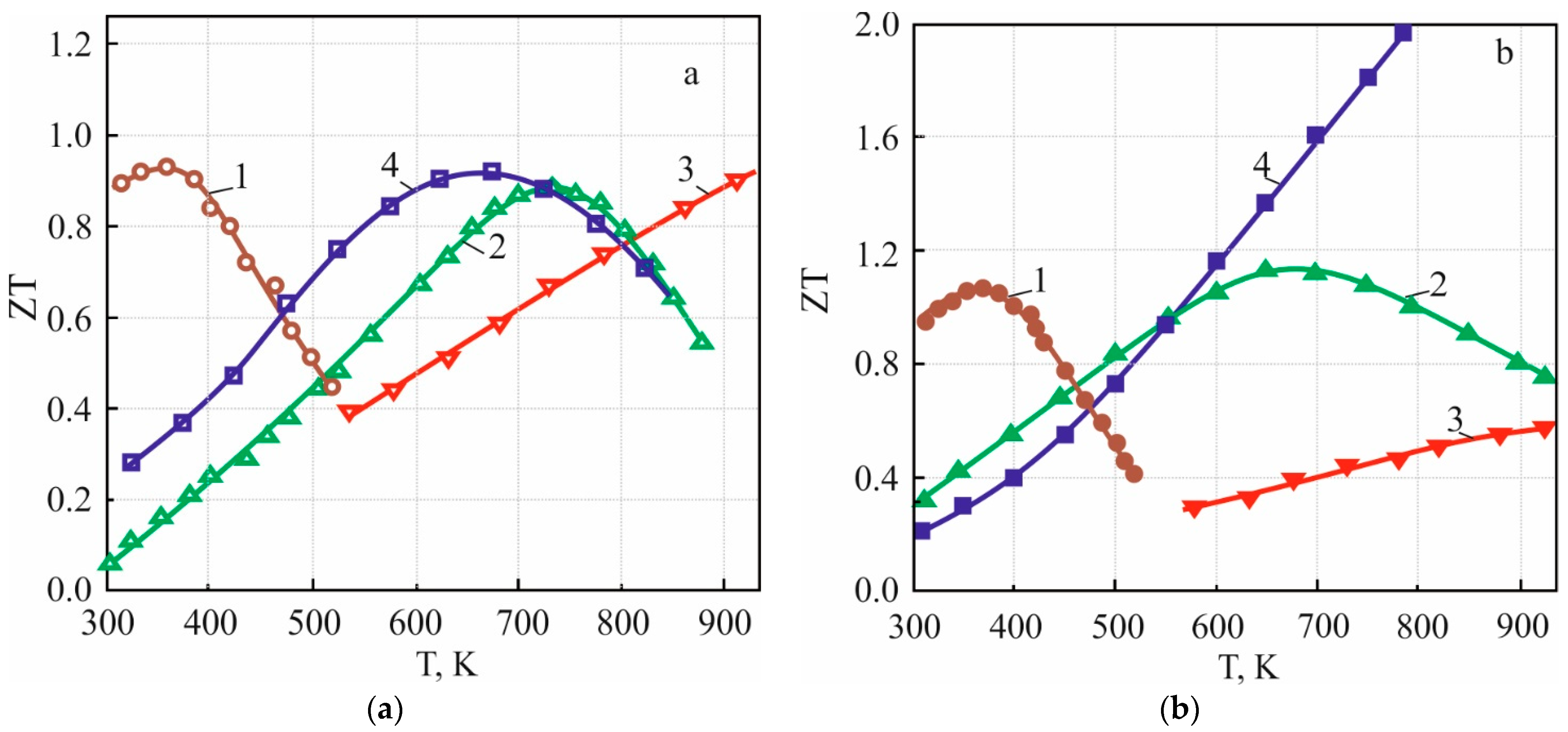
3.1. The Thermoelectric Materials for Application at 300–600 K Temperature Range

Presently, the most effective thermoelectric materials operating at the 300–600 K temperature range are solid solutions of Bi2Te3-Bi2Se3 (Bi2Te3−xSex) for n-type thermoelectrics. The best p-type thermoelectrics are solid solutions of Bi2Te3-Sb2Te3 (Bi2−xSbxTe3), as shown in Figure 1 [25,26,27,28,29,43]. The temperature dependences of the thermoelectric characteristics (S, σ, κ, and ZT) over the 300–600 K temperature range for these p-type materials prepared by SPS were presented in [29].

3.2. The Thermoelectric Materials for Application at 600–900 K Temperature Range

3.2.1. n-Type

The best n-type thermoelectric materials for the 600–900 K temperature range are PbTe-based compounds (Figure 1a [32,33,34]). As shown in [40,41], indium doping in lead telluride creates an In local level in the conduction band. This leads to localization of Fermi level close to the edge of the conduction band, which imparts an optimal value of ZT [45,46,47,48]. Increasing ZT has been achieved by co-doping of PbTe with indium and iodine (I is a donor impurity in PbTe [32]) [41]. The temperature dependence of the thermoelectric characteristics over the 600–900 K temperature range for n-type Pb1−xInxTe1−yIy thermoelectrics were presented in [41]. A value of the dimensionless figure of merit ZT for Pb0.999In0.001Te0.999I0.001 is ~1.3 at operating temperature T = 750 K, which is one of the maximal values for n-type PbTe.

3.2.2. p-Type

The best p-type thermoelectric materials for the 600–900 K temperature range are AIVBVI semiconductor compounds (PbTe and GeTe) (Figure 1b [35,36,37]). Recently, significant progress has been made in increasing ZT for GeTe doped by Bi (Ge1−xBixTe solid solutions) [42]. For these compositions, a significant decrease is observed in the hole concentration imparting a high ZT value. Moreover, GeTe thermoelectric has satisfactory mechanical properties. On the other hand, high-efficiency p-type PbTe (Figure 1) has poor mechanical properties [49,50,51]). This characteristic is necessary for fabrication of thermoelectric modules [27,52,53].
The temperature dependences of the thermoelectric characteristics over a 600–900 K temperature range for p-type Ge1−x−yBixPbyTe, prepared by SPS, were presented in [42]. The parameter ZT for Ge0.96Bi0.04Te has a value of ~2.0 at the temperature T = 700 K and it remains practically constant up to 900 K.

4. Application

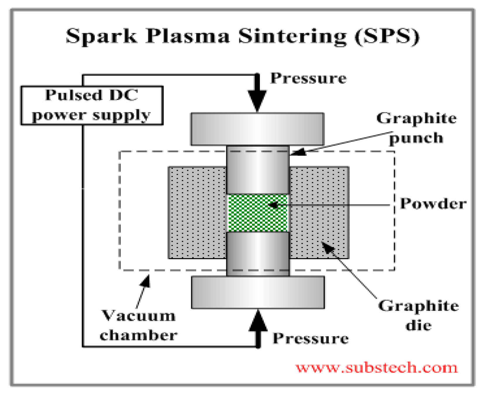
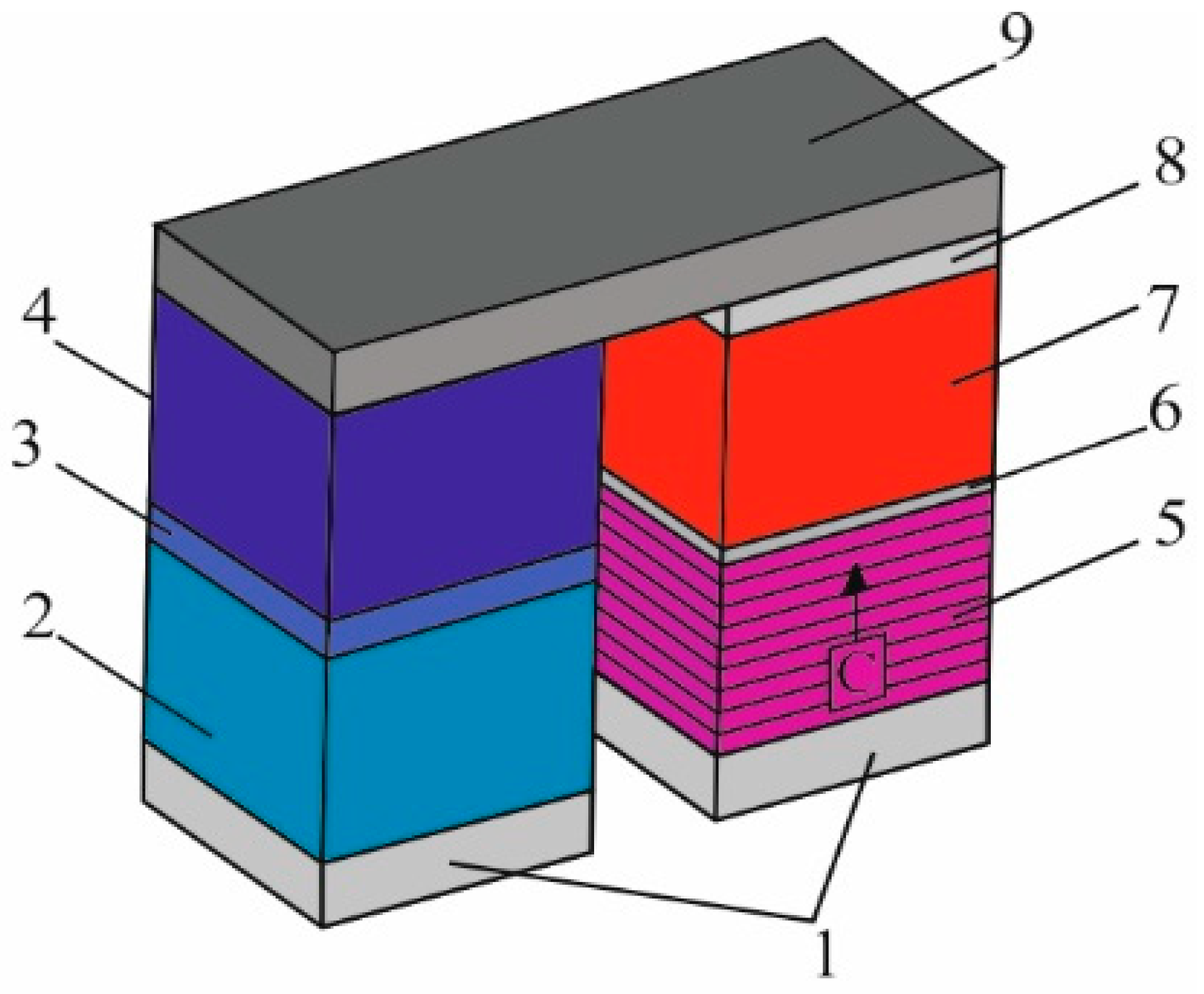
4.1. Thermoelectric Module

To obtain maximum TE efficiency, we developed a thermoelectric module based on a multilayered TE unicouple [25]. The design and composition of each layer is presented in Figure 4. The efficiency of such multilayer unicouples was measured by the set-up presented in [23] and found to have a high value of ~14–15% for Th = 900 K and Tc = 320 K. A thermoelectric module (TEM) is assembled in the following route:
  • Replication of many TE unicouples by SPS process.
  • Assembly into an aluminum cassette.
  • Forming the module by hot pressing at temperature T ≈ 700 K at pressure p ≈ 100 T under argon atmosphere.
  • Setting the module in a 1 mm thick stainless-steel case [25]. Electrical insulation between the case and the TE module is provided by 0.1 mm thick mica.
  • Sealing the protective case and filling it with argon at a pressure p ≈ 760 Torr.
The characteristics of the thermoelectric module are presented in Table 1.

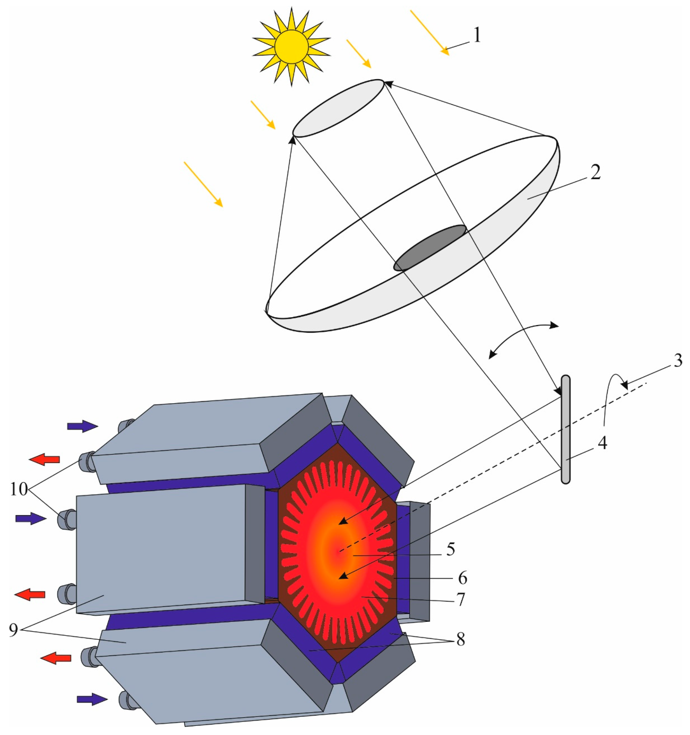
4.2. Solar Hybrid System Using TEG (SHTES)

Based on TEG, a novel solar hybrid system of electric energy and heat is presented in Figure 5. Solar radiation (1) is collected by the reflector (2), which is oriented by a tracking system (3) (heliostat) onto absorber (5). There, the radiation is converted to thermal energy and accumulated in a phase-change material (PCM). The melting temperature of PCM is close to the optimal operating temperature of the TEG (8). Up to 15% of the thermal energy is converted into electricity due to the difference ΔT between the temperatures of the thermal storage and the radiators (9) on the cold side of TEM.

4.2.1. Reflector

In Figure 5, the reflector (2) is a parabolic dish that tracks the sun. It is constructed using modular segments that can be combined to create dishes ranging from 3 to 10 m in diameter, depending on the desired power and corresponding reflective surface area. This reflector is designed for ease of use, high precision, and low weight and cost. The low weight allows for precise tracking using small motors and drive mechanisms. The reflective surface is made of mirror-coated facets with a reflectivity of approximately 95%. These facets are identical, curved in a special way, allowing for individual alignment. Additionally, the individual alignment of the facets can be used to control the distribution of energy on the target, resulting in high precision with an accuracy of less than 0.5 milliradians.

4.2.2. Sun Tracking System

The sun tracking system presented (3) in Figure 5 is based on a polar co-ordinate system, thus enabling easy and accurate tracking. The developed design, which combines the main axis of motion with the optical axis, enables directing of the concentrated solar radiation onto a stationary receiver with minimal optical losses and without the need to mobilize a thermal receiver.

4.2.3. Thermal Energy Storage

The solar receiver and absorber (5) are integrated into the thermal storage vessel (7) to reduce thermal and hydrostatic loads and ensure uniform absorption. Solar energy absorbed by the receiver makes the PCM in the accumulator heat and melt. The phase transition keeps the temperature of the hot end of the thermal converter nearly constant and allows generation of electricity during the night. It is proposed to use Al alloys with a melting point around 900–930 K as PCM. Al is environmentally harmless, nontoxic, and readily available. It has relatively high storage density (400 Joules per gram) and its melting point can be tuned by alloying with copper. According to data from the National Renewable Energy Laboratory, the average solar insolation (or solar radiation) in Israel is about 5.5 kilowatt-hours per square meter per day. To supply TEG with ~15% efficiency and electric power output of 700 W, we need about 5 kW heat power flow. Thus, to support this power flow during 24 h, we need 24 × 5 = 120 kWh per day of solar energy, which can be collected from 120/5.5 ≈ 22 m2 of insolated area. For thermal power of Q = 5 kW, a rough estimate of the amount of Al gives about 540 kg. This amount of Al is necessary to store the solar energy collected during the day time (12 h) as energy of melting, taking into account the heat of melting hAl = 10.79 kJ/mol.

4.2.4. Solar Thermoelectric Generator (STEG)

When STEG is used as a stand-alone solar power converter, it can be characterized in terms of power, operating temperature, location, and heat utilization. The temperature of the heat exchanger 6 (Figure 5) is maintained at about 900 K. The STEG consists of six thermoelectric modules (8), connected thermally in parallel and electrically in series. Each cold side of the TEM (8) is connected to a radiator (9). Water circulates in the heat sinks at a temperature of 320–340 K. This hot water can be stored in a thermostated tank, such as a solar boiler, and have secondary usage, such as domestic heating, hot water supply, or thermal desalination of water.
It is expected that a prototype of such a hybrid STEG can produce ~700 W of electricity [23]. The remaining ~3000 W of thermal energy can have secondary usage. The advantage of such a system is high stability without operational maintenance during the year and a long service life of more than ~20–25 years.

4.3. Solar Thermal Desalination of Water

In arid zones, the heat concentrated on TEG may be utilized to produce renewable electric power, while all the waste heat may be used to produce another necessary resource by thermal desalination of water [54,55]. Thermal desalination is a process of removing salt and other impurities from water by using heat to evaporate the water and then condense the vapor into pure water. There are two main approaches for thermal desalination: direct and indirect.
Direct methods of thermal desalination involve using a single device where evaporation and condensation take place simultaneously. These techniques are typically used to produce water for small communities and households. Examples of direct solar thermal desalination methods include solar stills, water cones, and water pyramids. Solar stills work by using sunlight to heat a shallow container of saltwater. As the water evaporates, it condenses on a sloping surface and drips into a collection container, leaving behind the salt and other impurities. Water cones and water pyramids are similar in design, using a sloping surface to collect and condense water vapor. These methods of thermal desalination are relatively simple and inexpensive, making them a good option for small-scale water desalination projects in arid regions. However, they may not be efficient enough to meet the needs of larger communities or industries.
Indirect methods ordinarily have two steps: a solar collector and a desalination unit. The solar collector is designed to absorb solar radiation and convert it into heat energy. This heat energy is then transferred to a desalination unit, where the actual process of water desalination takes place. The solar collector used in indirect methods can contain a TEG that produces electricity and supplies the exhaust heat in a series connection to the desalination system. These systems may be membrane distillation, multistage flash, and multiple-effect evaporation systems. In the multistage flash method, hot water is delivered from the steam boiler to the first stage, where a portion of water flashes. The vapors condensate and deliver heat to the feed water. The remaining water continues to the second stage, where it flashes at lower pressure and temperature and so on. In the multiple-effect evaporation method, hot steam is delivered from the steam boiler to the first stage, where it condensates and delivers heat to the feed water, which evaporates at lower pressure and temperature and continues to the next step.
Some solar collectors, such as solar ponds, can use low-grade heat up to 350 K. Solar ponds are shallow ponds filled with saltwater and have a layer of black sediment at the bottom that absorbs sunlight and converts it into thermal energy. This method is particularly useful in regions where there is abundant sunlight but low wind speeds. Other desalination systems require higher temperatures of up to 500 K to achieve higher thermodynamic efficiency. These systems are typically more complex and expensive, but they are more suitable for large-scale water desalination projects. Thus, indirect methods of thermal desalination are more efficient and can handle larger volumes of water than direct methods, making them ideal for industrial and commercial applications in arid regions.

5. Conclusions

A unique hybrid solar system using a high-performance STEG was developed. The main advantages of this system are the following:
-
All the energy of the solar spectrum is converted by STEG to electrical and heat energies.
-
The solar energy is absorbed by a PCM thermal storage, which saves the heat during long time and temperature ~900 K due to the reversible transition of aluminum alloy between the solid and liquid states.
-
This system does not require buffer electric accumulators.
-
A high conversion efficiency up to 15% (electric part) multilayer thermoelectric module was developed. For each leg of each TE unicouple, two types of high-efficiency thermoelectric materials were selected to ensure high efficiency along a wide range of operating temperatures. The low-temperature materials (for the 300–600 K temperature range) are based on Bi2Te3 compound. The middle-temperature materials (for the 600–900 K temperature range) are n-type PbTe doped by indium, which provided a practically constant value of average figure of merit ZT at a wide temperature range. The thermoelectric of p-type is GeTe semiconductor compound doped by Bi up to 5%.
-
The waste solar energy due to Carnot cycle can be collected in the heat radiators at a temperature of 320–350 K and has secondary usage, such as domestic heating or water thermal desalination.
We expect that a prototype of such a solar hybrid system can produce ~700 W of electrical energy and ~3 kW of heat energy for heating and hot water supply (in the domestic variant).

Author Contributions

S.M.—principal investigator; R.Z.S.—methodology; B.D.—investigation and visualization; F.G.—project management and conceptualization; Z.D.—supervision. All authors have read and agreed to the published version of the manuscript.

Funding

This work was supported by National Natural Science Foundation of China (52272123).

Data Availability Statement

The raw/processed data required to reproduce these findings cannot be shared at this time as the data also form part of an ongoing study.

Conflicts of Interest

The authors declare no conflict of interest.

References

  1. Achkari, O.; El Fadar, A. Latest developments on TES and CSP technologies–energy and environmental issues, applications and research trends. Appl. Therm. Eng. 2020, 167, 114806. [Google Scholar] [CrossRef]
  2. Pimentel, D. Renewable and solar energy technologies: Energy and Environmental Issues. In Biofuels, Solar and Wind as Renewable Energy Systems: Benefits and Risks; CHOICE: Current Reviews for Academic Libraries: Middletown, CT, USA, 2008; pp. 1–17. [Google Scholar]
  3. Zheng, X.F.; Liu, C.X.; Yan, Y.Y.; Wang, Q. A review of thermoelectrics research–recent developments and potentials for sustainable and renewable energy applications. Renew. Sustain. Energy Rev. 2014, 22, 486–503. [Google Scholar] [CrossRef]
  4. Sedaghat, M.; Siadatan, A.; Taheri, B. Photovoltaic system with sliding mode control for work on for maximum powerpoint. Comput. Intell. Electr. Eng. 2019, 9, 77–90. [Google Scholar]
  5. Brock, A.; Benjamin, K.; Sovacool, B.K.; Andrew Hook, A. Volatile photovoltaics: Green industrialization, sacrifice zones, and the political ecology of solar energyinGermany. Ann. Am. Assoc. Geogr. 2021, 11, 1756–1778. [Google Scholar] [CrossRef]
  6. Echegaray, F. Understanding stakeholders’ views and support for solar energy in Brazil. J. Clean. Prod. 2014, 63, 125–133. [Google Scholar] [CrossRef]
  7. Maka, A.O.; Alabid, J.M. Solar energy technology and its roles in sustainable development. Clean Energy 2022, 6, 476–483. [Google Scholar] [CrossRef]
  8. Tabassum, S.; Rahman, T.; Islam, A.U.; Rahman, S.; Dipta, D.R.; Roy, S.; Mohammad, N.; Nawar, N.; Hossain, E. Solar energy in the United States: Development, challenges and future prospects. Energies 2021, 14, 8142. [Google Scholar] [CrossRef]
  9. Indira, S.S.; Vaithilingam, C.A.; Chong, K.-K.; Saidur, R.; Faizal, M.; Abubakar, S.; Paiman, S. A review on various configurations of hybrid concentrator photovoltaic and thermoelectric generator system. Solar Energy 2020, 201, 122–148. [Google Scholar] [CrossRef]
  10. Maslamani, T.M.; Omer, A.I.; Majid, M. Development of solar thermoelectric generator. Eur. Sci. J. 2014, 10, 123–134. [Google Scholar]
  11. Field, H. Solar cell spectral response measurement errors related to spectral band width and chopped light waveform. In Proceedings of the Conference Record of the Twenty Sixth IEEE Photovoltaic Specialists Conference-1997, Anaheim, CA, USA, 29 September–3 October 1997; pp. 471–474. [Google Scholar]
  12. Huang, G.; Curt, S.R.; Wang, K.; Markides, C.N. Challenges and opportunities for nanomaterials in spectral splitting forhigh-performance hybrid solar photovoltaic-thermal applications: A review. Nano Mater. Sci. 2020, 2, 183–203. [Google Scholar] [CrossRef]
  13. Guney, M.S. Solar power and application methods. Renew. Sustain. Energy Rev. 2016, 57, 776–785. [Google Scholar] [CrossRef]
  14. Siegel, N.P. Thermal energy storage for solar power production. Wiley Interdiscip. Rev. Energy Environ. 2012, 1, 119–131. [Google Scholar] [CrossRef]
  15. Jia, H.; Taheri, B. Model identification of solid oxide fuel cell using hybrid Elman neural network/quantum pathfinder algorithm. Energy Rep. 2021, 7, 3328–3337. [Google Scholar] [CrossRef]
  16. Huang, G.; Wang, K.; Curt, S.; Franchetti, B.; Pesmazoglou, I.; Markides, C.N. On the performance of concentrating fluid-based spectral-splitting hybrid PV-thermal (PV-T) solar collectors. Renew. Energy 2021, 174, 590–605. [Google Scholar] [CrossRef]
  17. Cotfas, D.T.; Cotfas, P.A.; Mahmoudinezhad, S.; Louzani, M. Critical factors and parameters for hybrid Photovoltaic-Thermoelectric systems; review. Appl. Therm. Eng. 2022, 215, 118977. [Google Scholar] [CrossRef]
  18. Dario Narducci, D.; Lorenzi, B. Hybrid thermoelectric-photovoltaic solar harvesters: Technological and economic issues. Jpn. J. Appl. Phys. 2023, 62, SD0801. [Google Scholar] [CrossRef]
  19. Abdoa, A.; Ookawaraa, S.; Ahmeda, M. Performance evaluation of a new design of concentrator photovoltaic and solar thermoelectric generator hybrid system. Energy Convers. Manag. 2019, 195, 1382–1401. [Google Scholar] [CrossRef]
  20. Lia, G.; Shittu, S.; Zhou, K.; Zhao, X.; Ma, X. Preliminary experiment on a novel photovoltaic-thermoelectric system in summer. Energy 2019, 188, 116041. [Google Scholar] [CrossRef]
  21. Wen, X.; Ji, J.; Song, Z.; Li, Z.; Xie, H.; Wang, J. Comparison analysis of two different concentrated photovoltaic/thermal-TEG hybrid systems. Energy Convers. Manag. 2021, 234, 113940. [Google Scholar] [CrossRef]
  22. Beeri, O.; Rotem, O.; Hazan, E.; AKatz, E.A.; Braun, A.; Gelbstein, Y. Hybrid photovoltaic-thermoelectric system for concentrated solar energy conversion: Experimental realization and modeling. J. Appl. Phys. 2015, 118, 115104. [Google Scholar] [CrossRef]
  23. Bairamov, R.B.; Dashevskii, Z.M.; Kolomoets, N.V.; Shmatok, Y.u.I. Investigation of a solar water-lifting unit with an external-heat-supply engine. Appl. Solar Energy 1985, 21, 49–53. [Google Scholar]
  24. Kolomoets, N.V.; Shmatok, Y.I.; Dashevskii, Z.M. Test of water-lifting unit with externally heated engine using solar energy and biogas. Appl. Solar Energy 1989, 25, 94–96. [Google Scholar]
  25. Dashevsky, Z.; Jarashneli, A.; Unigovski Ya Dzunzda, B.; Feng Gao Shneck, R.Z. Development of a High Perfomance GasThermoelectric Generator (TEG) with Possibible Use of Waste Heat. Energies 2022, 15, 3960. [Google Scholar] [CrossRef]
  26. Dashevsky, Z.; Skipidarov, S. Investigating the performance of bismuth-antimony telluride. In Novel Thermoelectric Materials and Device Design Concepts; Springer: Berlin/Heidelberg, Germany, 2019; pp. 3–21. [Google Scholar]
  27. Rad, M.K.; Rezania, A.; Omid, M.; Rajabipour, A.; Rosendahl, L. Study on material properties effect for maximization of thermoelectric power generation. Renew. Energy 2019, 138, 236–242. [Google Scholar]
  28. Mamur, H.; Bhuiyan, M.; Korkmaz, F.; M Nil, M. A review on bismuth telluride (Bi2Te3) nanostructure for thermoelectric applications. Renew. Sustain. Energy Rev. 2018, 82, 4159–4169. [Google Scholar] [CrossRef]
  29. Maksymuk, M.; Dzundza, B.; Matkivsky, O.; Horichok, I.; Shneck, R.; Dashevsky, Z. Development of the high performancethermoelectric unicouple based on Bi2Te3 compounds. J. Power Sources 2022, 530, 231301. [Google Scholar] [CrossRef]
  30. Gayner, C.; Kar, K.K. Recent advances in thermoelectric materials. Prog. Mater. Sci. 2016, 83, 330–382. [Google Scholar] [CrossRef]
  31. Sootsman, J.R.; Chung, D.Y.; Kanatzidis, M.G. New and old concepts in thermoelectric materials. Angew. Chem. Int. Ed. 2009, 48, 8616–8639. [Google Scholar] [CrossRef]
  32. Gelbstein, Y.; Dashevsky, Z.; Dariel, M.P. High performance n-type PbTe-based materials for thermoelectric applications. Physica B 2005, 363, 96–205. [Google Scholar] [CrossRef]
  33. Parashchuk, T.; Horichok, I.; Kosonowski, A.; Cherniushok, O.; Wyzga, P.; Cempura, G.; Kruk, A.; Wojciechowski, K.T. Insight into the transport properties and enhanced thermoelectric performance of n-type Pb1−xSbxTe. J. Alloys Comp. 2020, 860, 158355. [Google Scholar] [CrossRef]
  34. Knura, R.; Parashchuk, T.; Yoshiasab, A.; Wojciechowski, K.T. Origins of low lattice thermal conductivity of Pb1−xSnxTe alloys for thermoelectric applications. Dalton Trans. 2021, 50, 4323. [Google Scholar] [CrossRef]
  35. Parashchuk, T.; Wiendlocha, B.; Cherniushok, O.; Knura, R.; Wojciechowski, K.T. High Thermoelectric performance of p-type PbTe enabled by the synergy of resonance scattering and lattice softening. ACS Appl. Mater. Interfaces 2021, 13, 49027–49042. [Google Scholar] [CrossRef]
  36. Petsagkourakis, I.; Tybrandt, K.; Crispin, X.; Ohkubo, I.; Satoh, N.; Mori, T. Thermoelectric materials and applications for energy harvesting power generation. Sci. Technol. Adv. Mater. 2018, 19, 836–862. [Google Scholar] [CrossRef] [Green Version]
  37. Parashchuk, T.; Shabaldin, A.; Cherniushok, O.; Konstantinov, G.; Horichok, I.; Burkov, A.; Dashevsky, Z. Enhanced thermoelectric properties of p-type Ge1−xPbxTe alloys due to decrease of lattice thermal conductivity. J. Phys. B 2020, 596, 412397. [Google Scholar] [CrossRef]
  38. Romanjek, K.; Vesin, S.; Aixala, L.; Baffie, T.; Bernard-Granger, G.; Dufourcq, J. High Perormance Silicon–Germanium-Based Thermoelectric Modules for Gas Exhaust Energy Scavenging. J. Electron. Mater. 2015, 44, 2192–2202. [Google Scholar] [CrossRef]
  39. Delime-Codrin, K.; Omprakash, M.; Ghodke, S.; Sobota, R.; Adachi, M.; Kiyama, M.; Matsuura, T.; Yamamoto, Y.; Matsunami, M.; Takeuchi, T. Large figure of merit ZT = 1.88 at 873 K achieved with nanostructured Si0.55Ge0.35 (P0.10Fe0.01). Appl. Phys. Express 2019, 12, 045507. [Google Scholar] [CrossRef]
  40. Parashchuk, T.; Dashevsky, Z.; Wojciechowski, K. Feasibility of a high stable PbTe:In semiconductor for thermoelectric energy applications. J. Appl. Phys. 2019, 125, 245103. [Google Scholar] [CrossRef]
  41. Wojciechowski, K.T.; Parashchuk, T.; Wiendlocha, B.; Cherniushok, O.; Dashevsky, Z. Highly efficient n-type PbTe developed by advanced electronic structure engineering. J. Mater. Chem. C 2020, 8, 13270–13285. [Google Scholar] [CrossRef]
  42. Dashevsky, Z.; Horichok, I.; Maksymuk, M.; Muchtar, A.R.; Srinivasan, B.; Mori, T. Feasibilityofhighperformancein p-type Ge1−xBixTe materials for thermoelectric modules. J. Am. Ceram. Soc. 2022, 105, 4500–4511. [Google Scholar] [CrossRef]
  43. Goltsman, B.M.; Kudinov, V.A.; Smirnov, I.A. Thermoelectric Semiconductor Materials Based on Bi2Te3; Nauka: Moskow, Russia, 1972. (In Russian) [Google Scholar]
  44. Kostyuk, O.; Dzundza, B.; Maksymuk, M.; Bublik, V.; Chernyak, L.; Dashevsky, Z. Development of Spark Plasma Syntering (SPS) technology for preparation of nanocrystalline p-type thermoelctrics based on (BiSb)2Te3. Phys. Chem. Solid State 2020, 21, 628–634. [Google Scholar] [CrossRef]
  45. Kaĭdanov, V.I.; Ravich, Y.I. Deep and resonance states in AIVBVI semiconductors. Sov. Phys. Usp. 1985, 28, 31–53. [Google Scholar] [CrossRef]
  46. Kaidanov, V.I. Resonance (Quasilocal) states in AIVBVI semiconductors. Defect Diffus. Forum 1993, 103, 387–406. [Google Scholar] [CrossRef]
  47. Dashevsky, Z.; Shusterman, S.; Dariel, M.P.; Drabkin, I. Thermoelectric efficiency in graded indium-doped PbTe crystals. J. Appl. Phys. 2002, 92, 1425–1430. [Google Scholar] [CrossRef]
  48. Heremans, J.P.; Wiendlocha, B.; Chamoire, A.M. Resonant levels in bulk thermoelectric semiconductors. Energy Environ. Sci. 2012, 5, 5510–5530. [Google Scholar] [CrossRef]
  49. Gelbstein, Y.; Gotesman, G.; Lishzinker, Y.; Dashevsky, Z.; Dariel, M.P. Mechanical properties of PbTe-based thermoelectricsemiconductors. Scr. Mater. 2008, 58, 251–254. [Google Scholar] [CrossRef]
  50. Gelbstein, Y.; Dashevsky, Z.; Dariel, M.P. The search for mechanically stable PbTe based thermoelectric materials. J. Appl. Phys. 2008, 104, 33–40. [Google Scholar] [CrossRef]
  51. Male, J.P.; Abdellaoui, L.; Yu, Y.; Zhang, S.; Pieczulewski, N.; Cojocaru-Miredin, O.; Scheu, C.; Snyder, G. Dislocations stabilized by point defects increase brittleness in PbTe. Adv. Funct. Mater. 2021, 2108006, 1–9. [Google Scholar] [CrossRef]
  52. Zoui, M.A.; Bentouba, S.; Stocholm, J.G.; Bourouis, M. A review on thermoelectric generators: Progress and application. Energies 2020, 13, 3606. [Google Scholar] [CrossRef]
  53. Tohidi, F.; Holagh, S.G.; Chitsaz, A. Thermoelectric Generators: A comprehensive review of characteristics and applications. Appl. Therm. Eng. 2022, 201, 117793. [Google Scholar] [CrossRef]
  54. Rabiee, H.; Khalilpour, K.R.; Betts, J.M.; Tapper, N. Energy-Water Nexus: Renewable-Integrated Hybridized Desalination Systems. Chapter 13; In Polygeneration with Polystorage for Chemical and Energy Hubs; Khalilpour, K.R., Ed.; Elseiver: Amsterdam, The Netherlands, 2019; pp. 41–72. [Google Scholar]
  55. Jones, E.; Qadir, M.; van Vliet, M.T.; Smakhtin, V.; Kang, S.M. The state of desalination and brine production: A global outlook. Sci. Total Environ. 2019, 657, 1343–1356. [Google Scholar] [CrossRef]
Figure 1. A solar water-lifting system with Stirling power convertor [21]. 1—parabolic concentrator. 2—tracking system. 3—Stirling power converter. 4—water pump. 5—valve. 6—water well. 7—water tank.
Energies 16 03036 g001
Figure 2. Temperature dependence of dimensionless figure of merit ZT as a function for different thermoelectric materials over 300–900 K temperature range [27,28,29,30,31,32,33,34,35,36,37,38,39,40,41,42,43]. (a) n-type: 1—Bi2Te3−xSex. 2—PbTe. 3—Si1−xGex. 4—Pb0.75Sn0.25Te. (b) p-type: 1—Bi2−xSbxTe3. 2—GeTe. 3—Si1−xGex. 4—PbTe.
Energies 16 03036 g002
Figure 3. Scheme of the spark plasma sintering (SPS) technique [44].
Energies 16 03036 g003
Figure 4. Schema of TE multilayer unicouple, designed to operate at a wide temperature difference between the hot and the cold sides of the unicouple ∆T~600 K. 1—Co contact. 2—n-type Bi2.7Se0.3Te3 layer. 3—n-type PbTe1−xIx layer. 4—n-type Pb1−xInxTe1−yIylayer. 5—p-type Bi0.5Sb1.5Te3 layer (orientation along c axis). 6—CoGe2 (anti-diffusion) layer. 7—p-type Ge1-xBixTe layer. 8—thin SnTe layer. 9—Fe contact.
Energies 16 03036 g004
Figure 5. Schematic view of solar hybrid system using thermoelectric generator (SHTES). 1—solar radiation. 2—reflector. 3—tracking system. 4—mirror. 5—solar receiver. 6—heat exchanger. 7—thermal storage. 8—thermoelectric module (TEM). 9—heat sink. 10—water connectors.
Energies 16 03036 g005
Table 1. The characteristics of thermoelectric module.
Dimensions,
mm–mm–mm
Number of UnicouplesHot Temperature,
Th, K
Cold Temperature, Tc, KSupply Voltage
U, V
Supply
Current
I, A
Electric Power
Pe, W
150–30–10100900300–320815120
Disclaimer/Publisher’s Note: The statements, opinions and data contained in all publications are solely those of the individual author(s) and contributor(s) and not of MDPI and/or the editor(s). MDPI and/or the editor(s) disclaim responsibility for any injury to people or property resulting from any ideas, methods, instructions or products referred to in the content.

