

Energy Management Strategies for Hybrid Loaders: Classification, Comparison and Prospect
1
Jiangsu XCMG Research Institute Co., Ltd., Xuzhou 221004, China
2
School of Materials and Physics, China University of Mining and Technology, Xuzhou 221116, China
*
Author to whom correspondence should be addressed.
Energies 2023, 16(7), 3018; https://doi.org/10.3390/en16073018
Submission received: 13 February 2023
/
Revised: 17 March 2023
/
Accepted: 23 March 2023
/
Published: 25 March 2023
(This article belongs to the Special Issue Energy Management Strategies for Battery and Hybrid Electric Vehicles)
Abstract
:As one of the effective and crucial ways to achieve the energy saving and emission reduction of loaders, hybrid technology has attracted the attention of many scholars and manufacturers. Selecting an appropriate energy management strategy (EMS) is essential to reduce fuel consumption and emissions for hybrid loaders (HLs). In this paper, firstly, the application status of drivetrain configuration of HLs is presented. Then, the working condition characteristics of loaders are analyzed. On the basis of this, the configurations of HLs are classified, and the features and research status of each configuration are described. Next, taking the energy consumption optimization of HLs as the object, the implementation principle and research progress of the proposed rule strategy and optimization strategy are compared and analyzed, and the differences of existing EMSs and future development challenges are summarized. Finally, combining the advantages of intelligent control and optimal control, the future prospective development direction of EMSs for HLs is considered. The conclusions of the paper can be identified in two points: firstly, although the existing EMSs can effectively optimize the energy consumption of HLs, the dependence of the strategy on the mechanism model and the vehicle parameters can reduce the applicability of the strategy to heterogeneous HLs and the robustness to a complex working condition. Secondly, combining the advantages of intelligent control and optimal control, designing an intelligent EMS not depending on the vehicle analytical model will provide a new method for solving the energy consumption optimization problem of HL.
1. Introduction
Loaders are the important equipment for modern engineering construction. Traditional loaders are generally driven by internal combustion engines, which have the defects of high energy consumption and emission. Under the traction of double carbon policy, more stringent requirements have been presented on the carbon emission levels of road and non-road vehicles. Therefore, it is imperative to develop new energy loaders with low-carbon environmental protection [1].
In recent years, the successful application of hybrid technology in new energy vehicles [2,3] has provided effective technical reference for the development of new energy loaders. Since Hitachi first applied hybrid technology to wheel loaders in 2003 [4], hybrid loaders (HLs) have made great progress in power configuration design [5] and energy-saving technology [6].
In general, the existing energy mixing types of HLs mainly include oil–electric hybrid, oil–hydraulic hybrid [7], and fuel cell hybrid [8]. The corresponding drivetrain configurations include series, parallel, and series–parallel types. The application status of drivetrain configuration of HLs at present is shown in Table 1. Different energy combinations and configuration topologies bring different energy-saving effects. Energy management strategies (EMSs) [9] are one of the important ways to achieve energy saving and consumption reducing of HLs, and control various types of energy or power sources through energy optimal distribution, to achieve high-efficiency utilization of vehicle energy.
Some researchers have recently reviewed the overall research status of hybrid technology in construction machinery [1,5,6], but little work has focused on the status analysis of EMSs for HLs. Considering that the working condition of the loaders is obviously different from that of excavators, bulldozers, and other construction machinery, and EMSs has a direct impact on the parameter matching and configuration design of HLs [1], the configuration and EMS research status of HLs are reviewed on the basis of the analysis of the working condition of the loaders. The current development status of EMSs for HLs is summarized here, and its prospective development trend is considered.
The rest of this paper is organized as follows: in Section 2, the configurations of HLs are introduced. The EMSs of HLs are classified and compared in Section 3. In Section 4, the development and trend of EMSs for HLs from different perspectives are discussed and analyzed. In Section 5, the conclusions of this paper are drawn.
2. Configurations of HLs
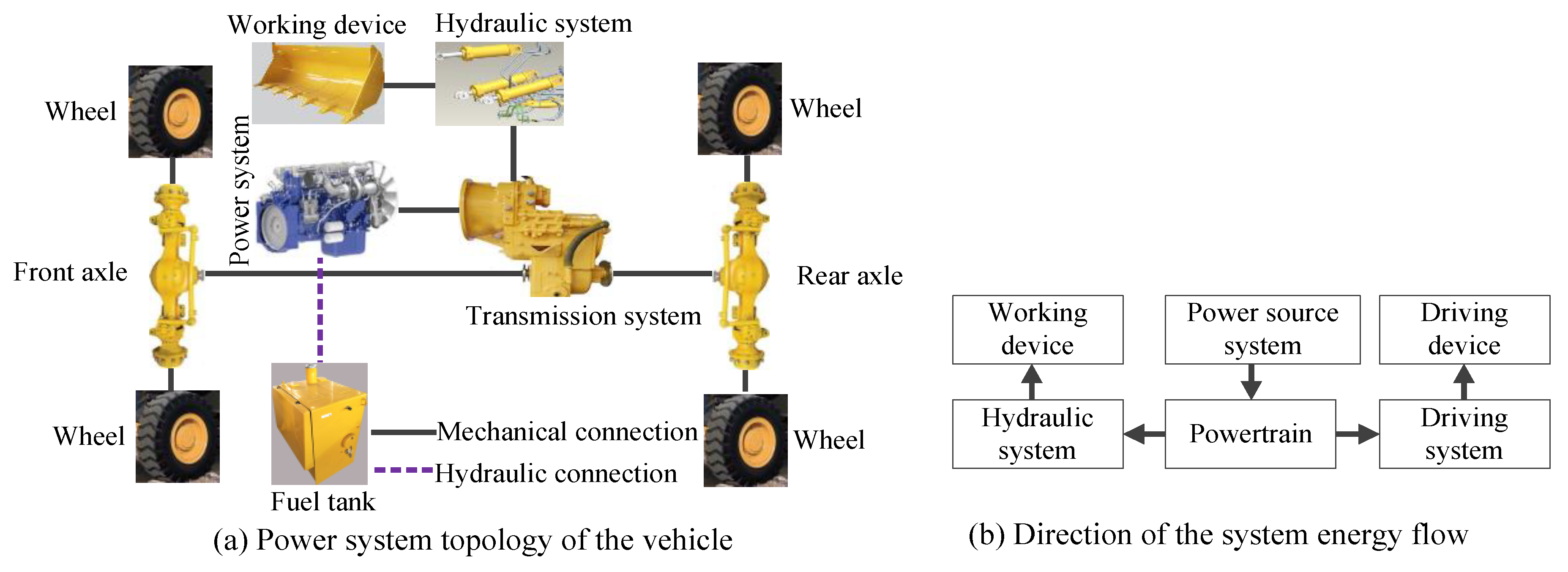
As a typical representative of earth–rock vehicles, the loaders complete operations through the cooperation of shoveling and driving, and their working conditions are complex and changeable. Correspondingly, the loaders are generally composed of a driving system and a hydraulic system. The drivetrain configuration of a traditional loader is shown in Figure 1. The driving system mainly includes power system, transmission system, front-rear axle, and wheels. Based on the analysis of Figure 1, the power relation between the driving system, hydraulic system, and power source of the traditional loader can be expressed by:
where , , and represent the output power, torque, and speed of the power source, respectively; , , , and denote the power, torque, speed, and driving force of the wheel, respectively; is the vehicle speed; , , , , and show the power, torque, speed, displacement, and pressure of the hydraulic system, respectively; is the energy transmission efficiency between the wheel and power source; and is the energy transmission efficiency between the hydraulic pump and power source.
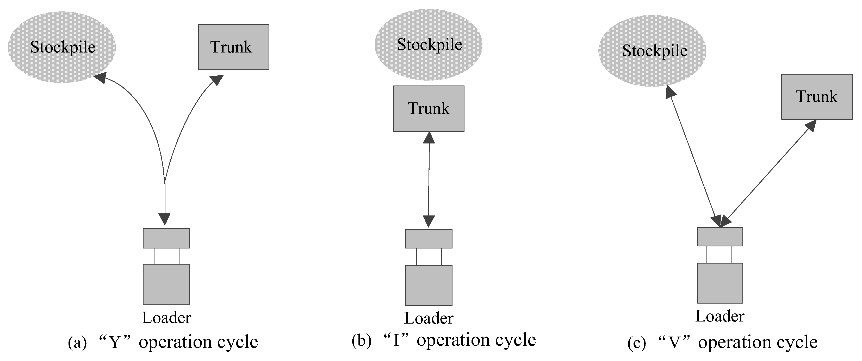
In general, a complete operation cycle of the loaders mainly contains four stages [19]: empty-load shoveling, full-load returning, full-load unloading, and empty-load returning. Each stage includes at least an acceleration process and a deceleration process. The corresponding cycle types are mainly classified into “Y”, “I”, and “V” types, as shown in Figure 2, and the “V” type operation cycle is the most typical among them [20].
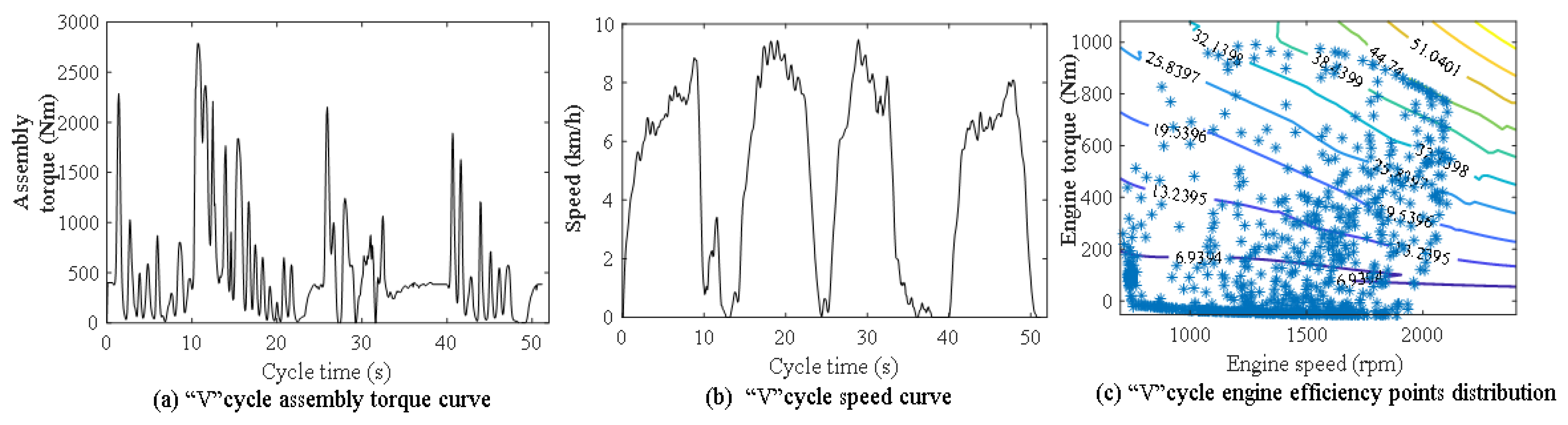
Different from on-road vehicles, loaders generally operate under low speed, high torque, and strong load impact conditions. The intermittency/low-efficiency operating points for the engine do not change much whether the cycle type is “Y”, “I”, or “V”, so only the operating conditions of the “V” cycle are described in detail. Accordingly, taking a 5 t traditional loader as an example, its power system output torque and vehicle speed curves under a complete “V” operation cycle are indicated in Figure 3a,b, and the efficiency point distribution of the engine is expressed in Figure 3c. It can be seen that the working process of loaders has obvious periodicity and strong repeatability. In addition, the low-speed and high-torque operating conditions make the engine operating points mainly concentrated in the low-efficiency area, where it is difficult to exert the best working performance of the engine. The frequent start–stop of the loaders with high torque during operation not only brings greater load pressure to the engine, but also easily causes a large amount of braking energy loss.
For this reason, inspired by the application of hybrid technology in automobiles, researchers have carried out in-depth research on hybrid technology for loaders [5,6,7,8,9], making the application of hybrid power systems on loaders possible. At present, according to whether the engine directly drives the vehicle and the energy types [5,6], the mainstream drivetrain configurations of HLs mainly contain oil–hydraulic hybrids, oil–electric hybrids, and fuel cell hybrids.
2.1. Oil–Hydraulic Hybrid
The oil–hydraulic hybrid technology has the characteristics of strong energy release and storage capacity, and high power density [7,21], which is applied to HLs earlier. In accordance with the power coupling mode of engine and hydraulic drive motor, the oil–hydraulic hybrid configurations mainly include series, parallel, and series–parallel types [6]. Considering the operation purpose and working condition characteristics of the loaders, the series and parallel oil–hydraulic hybrid configurations [22] are the most typical currently.
2.1.1. Series Oil–Hydraulic Hybrid
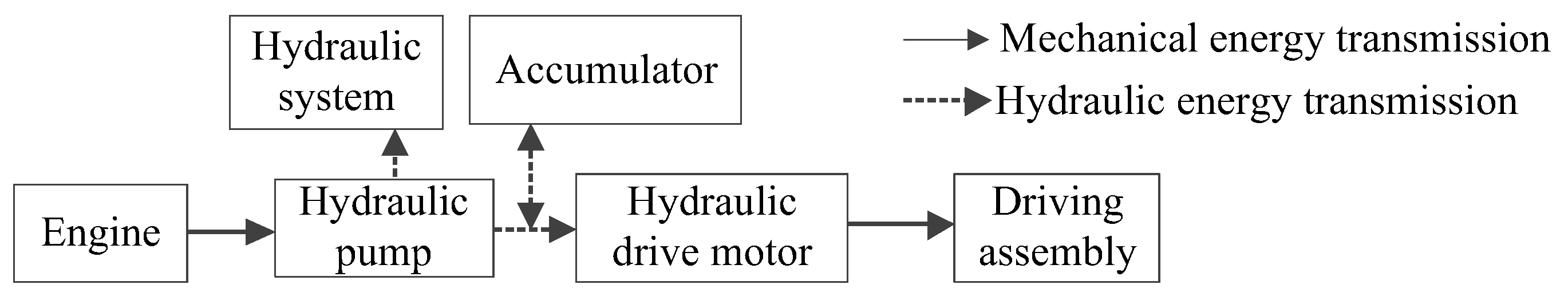
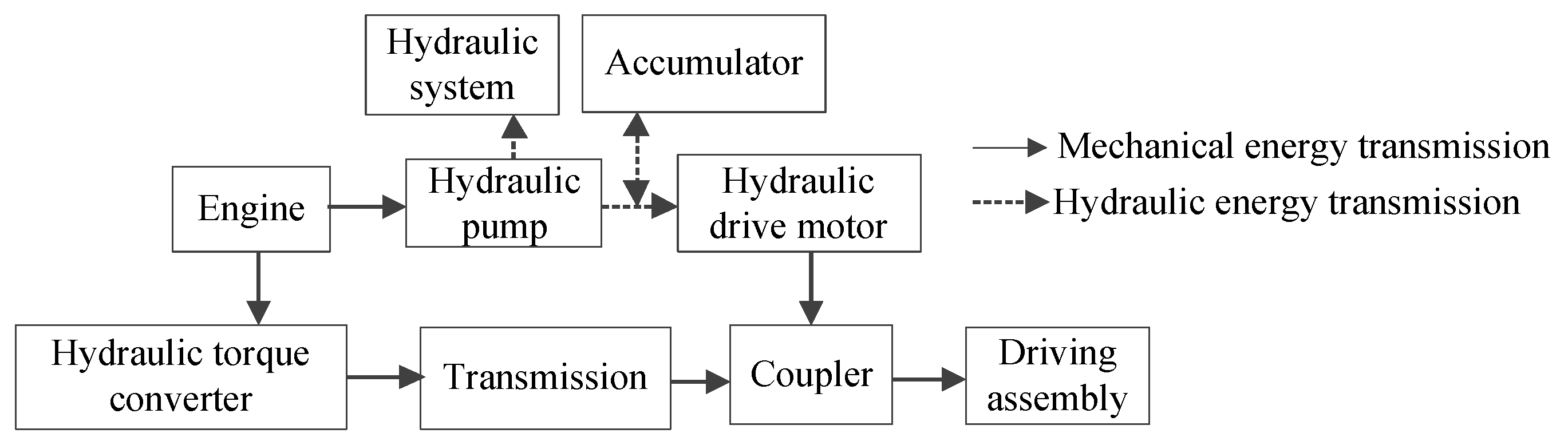
In the series oil–hydraulic hybrid system, the engine directly drives the hydraulic pump, and then the hydraulic pump drives the loading operation by the hydraulic system and chassis driving through the hydraulic drive motor. The specific configuration is represented in Figure 4. The running of the engine is independent of the vehicle speed and load, which makes it easier to operate near the optimum operating points, avoiding the low efficiency of idling and low-speed working conditions, and reducing emissions [23].
For example, in [24,25,26], a series hydraulic hybrid powertrain is presented, which is composed of the engine, variable displacement pump, four quadrant variable displacement pump-motor, high and low pressure hydraulic accumulators, and charge pump. The engine does not drive the vehicle directly, avoiding damage to the engine caused by frequent start–stop and the large torque output of the loader. The high-pressure accumulator can recover braking energy, and assists the engine power when the demand torque is large, improving the utilization rate of energy. In [27], a series oil–hydraulic hybrid wheel loader, which includes a hydrostatic transmission, two hydraulic accumulators, and a hydraulic load-sensing working circuit, is regarded as the research object. Then, to make the engine operate in high-efficiency areas, the engine speed can be dynamically adjusted by means of EMSs, achieving a fuel-saving rate of the system of 6.36%. Two main hydraulic pumps are applied in [28]; one of them is a load sensing pump, and the other one is the hydrostatic transmission. In this system, the 4/3 proportional control valves fitted with a pressure compensator are used to control the lift and bucket cylinders hydraulically. The energy between the pump and motor in the hydrostatic transmission is transmitted by hydraulic energy, avoiding the damage of load impact to the engine.

However, for the series oil–hydraulic hybrid, the engine does not drive the vehicle directly. Its energy transfers to the hydraulic pump and hydraulic motor, resulting in energy loss and low system efficiency, so the parallel oil–hydraulic hybrid system has been proposed.
2.1.2. Parallel Oil–Hydraulic Hybrid
As shown in Figure 5, different from the series oil–hydraulic hybrid configuration, in the parallel oil–hydraulic hybrid system the engine not only drives the HL through the hydraulic torque converter and transmission but also drives the hydraulic cylinder through the hydraulic pump to realize the steering and loading work [29,30]. Meanwhile, the excess power of the braking and driving system is reabsorbed by utilizing the characteristics of rapid energy absorption and release of the hydraulic accumulator. When the vehicle needs a large torque output, the accumulator releases this part of energy to drive the hydraulic motor, and then assists the engine to drive the vehicle to start and accelerate through the power coupling device, to achieve the purpose of saving fuel and reducing consumption [22,31].
In [22,30,31], the hydraulic regeneration system consisting of the hydraulic pump/motor, hydraulic accumulator, and relief valve is represented, and forms a dual power drive with the engine. During braking, the hydraulic pump/motor works in the pump condition and recovers the braking energy of the vehicle. It is stored in the high-pressure accumulator for the restart and digging conditions of the loader, to ensure that the engine works in the best fuel economy zone and reduce the overflow loss of the hydraulic working system. Wang et al. [32,33] introduce a power-split hydraulic hybrid drivetrain, including a planetary gear set, two variable displacement pumps, and a hydraulic accumulator. It not only decouples the vehicle speed from the engine speed, making the engine operate more efficiently, but also eliminates the operation interference between different subsystems in the traditional loader. In [7,34], the structure of a parallel hydraulic HL is illustrated, which involves the hydraulic system, hydrodynamic–mechanical transmission system, and energy regeneration system (ERS). The engine drives the hydraulic system via gears. The ERS can recover the braking energy of the HL, and reuses the energy to assist the engine to drive the chassis driving system while the vehicle needs large demand output.
However, the storage capacity of the hydraulic accumulator is restricted by the spatial arrangement of loaders, which limits its practical application range. For this purpose, some researchers have presented the oil–electric hybrid system.
2.2. Oil–Electric Hybrid
Different from the oil–hydraulic hybrid, the oil–electric hybrid system uses the battery or super capacitor as an energy storage device, which have higher energy density. According to the powertrain configuration, the oil–electric hybrid system can also be classified into serial, parallel, and serial–parallel types [35].
2.2.1. Series Oil–Electric Hybrid
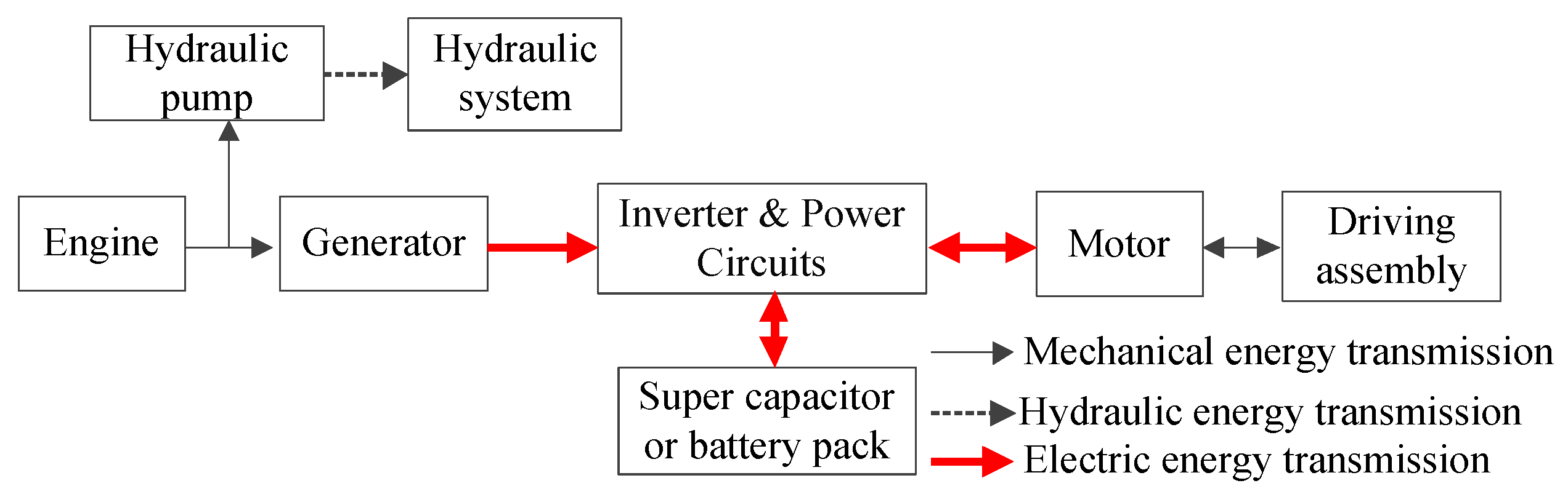
In the series oil–electric hybrid system, the engine drives the generator to generate electricity, and then provides power for the motor, together with the battery pack or the super capacitor [36]. The specific configuration is described in Figure 6. Compared with the traditional loaders, firstly, the series oil–electric hybrid system can improve the fuel utilization rate of the vehicle by controlling the engine to operate in the high-efficiency area [36]. Secondly, the engine does not directly drive the vehicle, which can effectively avoid engine damage caused by high-frequency impact of load in the operation process and prolong the service life of the engine. Finally, the motor can be used not only as a driving motor, but also as a generator, so that the braking energy of the vehicle during the cycle operation can be recycled to the energy storage system for reuse.
Specifically, in [36], a heavy series oil–electric hybrid power scheme is given, cancelling the hydraulic torque converter. A part of the energy of the engine is used to drive the hydraulic system, and the remaining energy is utilized to drive the generator. The electric energy of the generator drives the motor, and the excess energy is stored in the super capacitor. When the load is large, the super capacitor discharges and drives the motor, together with the generator. The system improves the energy utilization rate and torque converter transmission efficiency of HLs. In [37,38], a series electric hybrid powertrain is proposed, which consists of the engine–generator set, super capacitor, motor, and hydraulic pump. Combined with EMSs, the energy efficiency of the system makes a great improvement compared with the conventional loader. In [39], for improving energy efficiency for HL, a series oil–electric hybrid system including an electric load-sensing working system and electric drivetrain is given, whose power source contains the engine, generator, and battery pack. In the system, the driveline, engine operation, and lift and tilt functions are decoupled to reduce the energy consumption of the vehicle.
In addition, the engine of the configuration shown in Figure 6 drives the generator to produce the electric energy, and then drives the motor, causing some energy loss and reducing the power transmission efficiency of the engine. Therefore, some of the literature has improved the configuration from the following two aspects:
- (1)
- The hydraulic pump directly driven by the engine is changed to be driven by the motor, to improve the energy utilization rate of the hydraulic system [39].
- (2)
- For improving the electric energy utilization of the driving system and the vehicle controllability, the centralized driving of the chassis driving motor is replaced by a distributed wheel-driven system [14].
2.2.2. Parallel Oil–Electric Hybrid
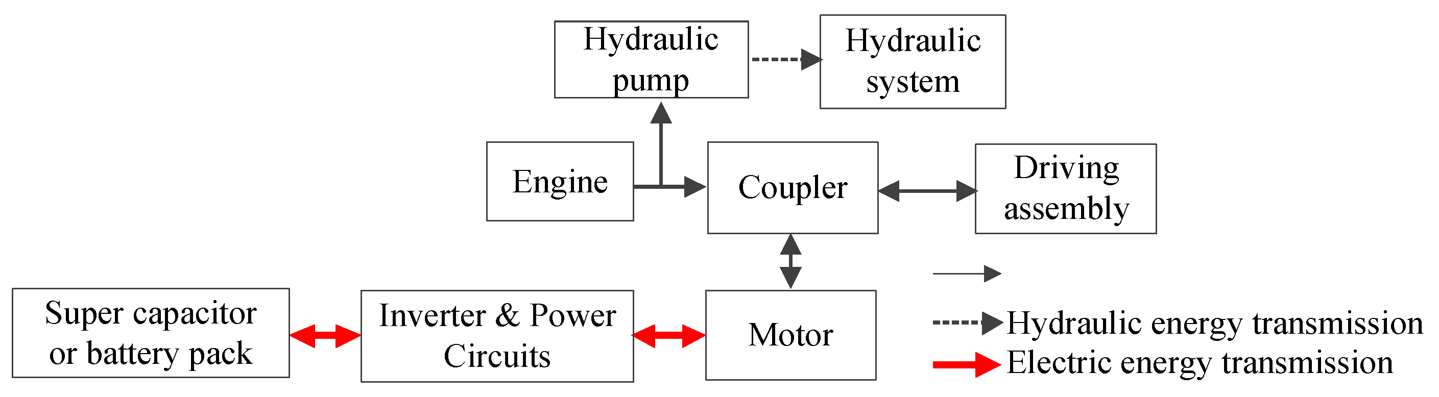
Different from the series oil–electric hybrid system, in the parallel oil–electric hybrid power system the engine and motor can drive the vehicle simultaneously or separately. The assistance of the motor makes the engine always operate in a high-efficiency area under low-, medium- and high-speed modes [40], improving the energy utilization of the vehicle. Its configuration is represented in Figure 7. In this process, the motor can drive the vehicle in different modes according to the working state and demand torque of the vehicle, which can be used as both a driving motor and a generator [40].
In [40,41,42,43], a parallel oil–electric scheme for HLs is introduced. The engine and motor are connected in parallel, and the super capacitor modules are used as the energy storage device. The energy from the engine and motor is divided into two parts. One part is transferred to the hydraulic torque converter, transmission, and driving axle, and finally reaches the wheels, and the other part is transmitted to the hydraulic system to drive the working device and control the vehicle steering, meeting the power requirements of complex conditions and improving the efficiency of the engine. In [13,44], the system structure of a coaxial parallel HL is proposed. The engine and motor are coaxially connected, and the super capacitor is used as an energy storage device.
Although the energy conversion efficiency of the parallel oil–electric hybrid is high, the engine and the driving wheel are mechanically connected. Thus, the engine working points cannot always be in the high-efficiency area, bringing higher fuel consumption. Therefore, some scholars have presented a series–parallel oil–electric hybrid configuration.
2.2.3. Series–Parallel Oil–Electric Hybrid
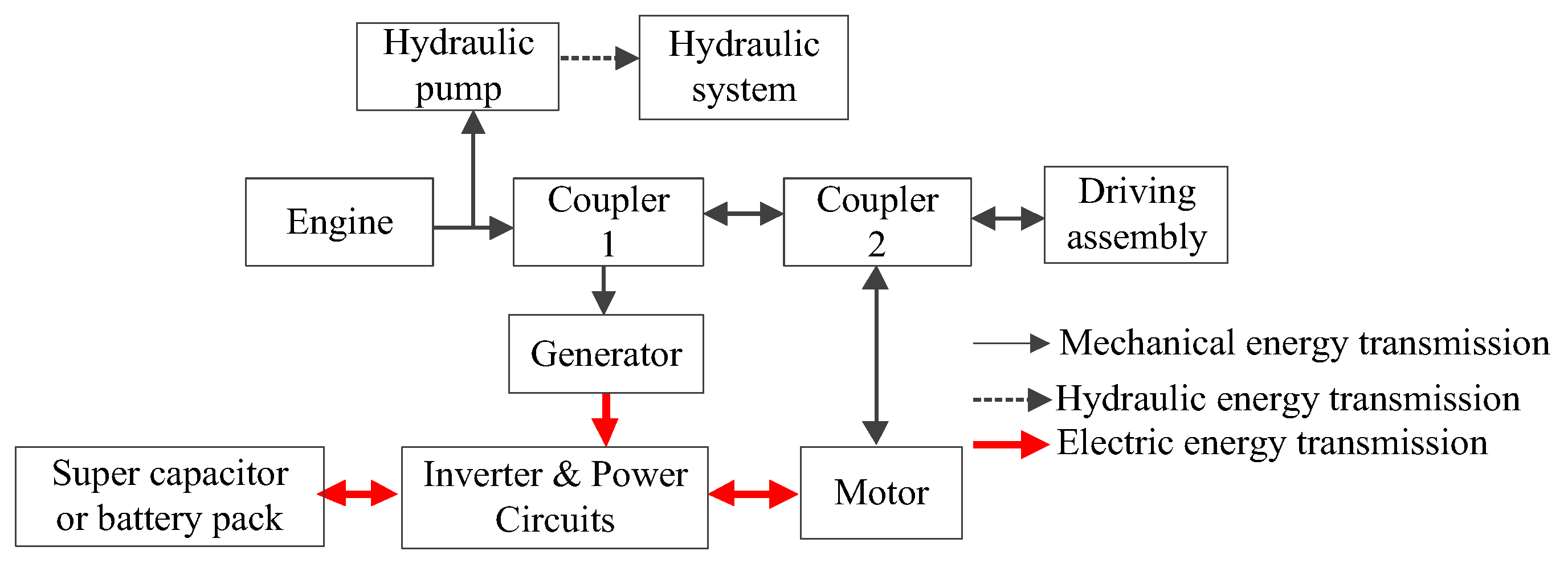
The series–parallel oil–electric hybrid system combines the advantages of series and parallel oil–electric hybrid systems and optimizes the fuel utilization rate of the engine by controlling the working states of the engine, generator, and motor [45], the system topology of which is mentioned in Figure 8. Coupler 1 is used to control the power coupling on–off between the engine and generator, and coupler 2 is utilized to control the power coupling on–off between the engine and motor. In the driving mode, the engine and motor can drive the driving assembly together or separately. In the energy recovery mode, the generator and motor can recover the excess power of engine and the braking energy of wheel together or separately.
In [45], an input–coupled output–split series–parallel oil–electric HL is proposed. The mechanical coupling between the engine and generator is jointed to the sun shaft, and the motor is connected to the ring shaft. The generator and planetary gear are not coaxially connected. The configuration usually can serve as a series structure to keep the engine operating in the high-efficiency area when the power demand is low. Meanwhile, by means of the planetary gear unit, the engine can also directly drive the vehicle while the power requirement is high. The Toyota hybrid system [46,47] is one of the most famous series–parallel configurations because it has excellent performances at all power requirements of a car driver. XU et al. [48] proposed a two-axis real-time series–parallel drive system. By controlling the front mechanical bridge clutch and the rear electric wheel clutch, it can quickly realize different combinations of series and parallel, and can arbitrarily switch between series and parallel modes according to the requirements of the vehicle working state.
Accordingly, compared with the series and parallel oil–electric hybrid systems, the series–parallel oil–electric hybrid system has a more flexible power combination mode when realizing the energy optimization of the vehicle, but it also increases the difficulty of design and control. Currently, it is rarely used on loaders.
2.3. Fuel Cell Hybrid
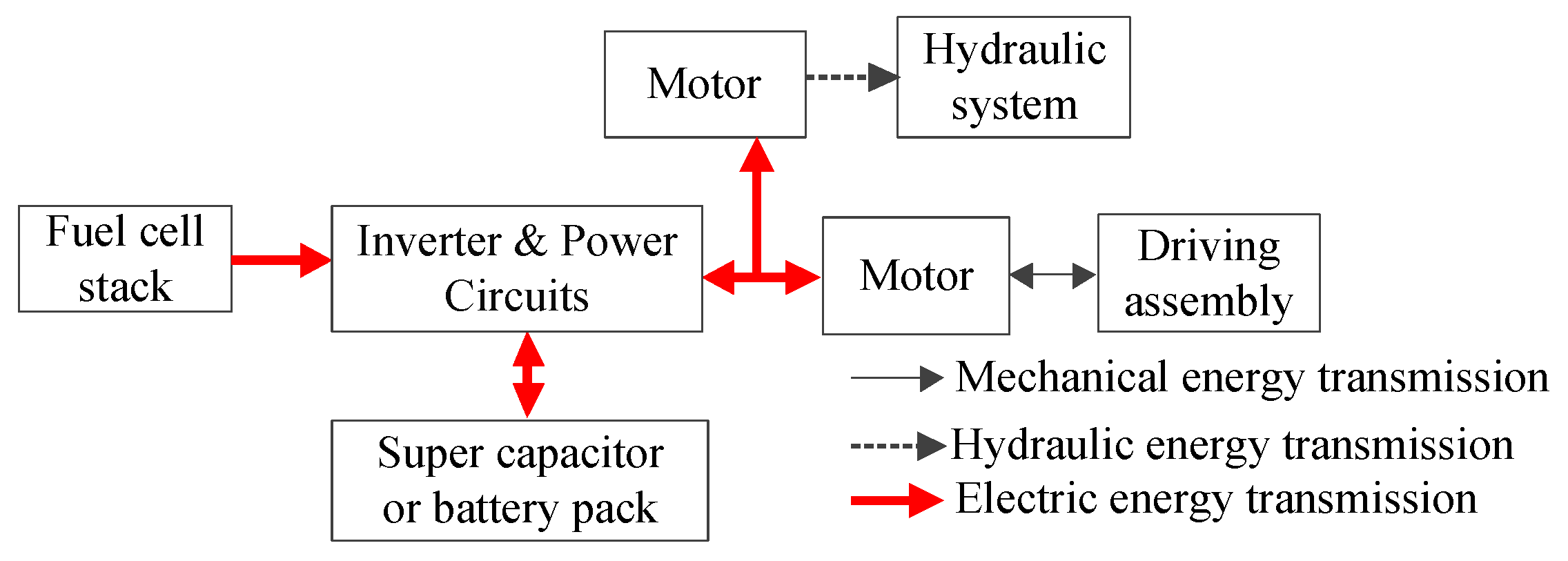
Different from the oil–electric and oil–hydraulic hybrid systems, the traditional engine is cancelled in the fuel cell hybrid configuration, whose power is replaced by the power of fuel cells and energy storage system [6]. In general, the fuel cell hybrid system contains a fuel cell stack, a super capacitor or battery pack, and motor driving powertrain [8], whose typical configuration is described in Figure 9. It takes the fuel cell as the main power source, and super capacitor or battery pack as the auxiliary energy, to meet the power requirements of the load hydraulic system and driving system through pure electric drive.
In [8,49,50,51], a fuel cell hybrid system for HLs is given, which mainly includes a fuel cell stack, a super capacitor pack, a motor-driven powertrain, and a motor-driven hydraulic system. The fuel cell stack is cascaded with a direct current (DC) bus through a boost converter, and the super capacitor pack is jointed to the DC bus via a bidirectional converter. In this system, as an auxiliary power supply, the super capacitor pack cooperates with the fuel cell system to meet the requirements of various working conditions of the loaders. Through the “peak cutting and valley filling” of the super capacitor, the efficient and stable operation of HLs is guaranteed, and the life of the fuel cell system is extended. Taking a fuel cell/battery hybrid system as the research object, LI et al. [52] combined multi-objective optimal model predictive control (MPC)-based energy management, reducing hydrogen consumption and prolonging the service life of the battery. In [53,54], the battery packs are used as an energy storage system, which can recover the braking energy by the load feedback and reduce the energy loss of the system. The output side of the battery packs is cascaded with a bidirectional DC/DC converter, directly controlling the charging and discharging power of battery packs. A unidirectional DC/DC converter is connected in series at the output side of the fuel cell stack to stabilize its output voltage.
As mentioned above, compared with the traditional loader, the hybrid configuration has the effect of saving energy and reducing emissions. However, the ability of energy saving and emission reduction for different hybrid configurations is different. In order to improve the energy consumption optimization effect of hybrid power configurations further, researchers have proposed various EMSs.
3. Energy Management Strategies of HLs
According to the configuration analysis, HLs belong to a nonlinear system with mechano–electro–hydraulic strong coupling features. The essence of its energy consumption optimization problem is to solve the optimal control problem of the nonlinear system with constraints. The general form of mathematical model is as follows:
where represents discrete time or distance point; denotes the performance index of HLs; the cost function characterizes the specific optimization indexes such as fuel consumption, equivalent fuel consumption, or energy utilization rate of the vehicle, which can be generally abbreviated as ; represents the state variables set of HLs, mainly including speed, state of charge (SoC) of energy storage system, and speed of hydraulic pump; is the control variables set of the drive system, which can be composed of engine output torque and motor output torque; expresses the state space equation of HLs system; is the constraint conditions of ; and is the control variables set of allowable input.
In order to achieve the optimal solution of (2), researchers have proposed rule-based (RB) EMSs and optimization-based (OB) EMSs for HLs in recent years [5,6].
3.1. RB EMSs
RB EMSs solve the energy consumption optimization problem of HLs by following the principle of power balance, not relying on the specific mathematical analysis model of (2). Namely, the output power or torque combination of the power system through EMSs must be equal to the vehicle demand. The strategy rules are mainly formulated by the designer’s experience to optimize the engine operating point, and then determine the torque combination of the engine and motor. In other words, obtained by RB EMSs is essentially an empirical solution, whose pros and cons depend largely on the experience of the designer. Nowadays, RB EMSs are divided into deterministic RB EMSs and fuzzy RB EMSs according to whether the relevant parameters in the strategy rule base are determined.
3.1.1. Deterministic RB EMSs
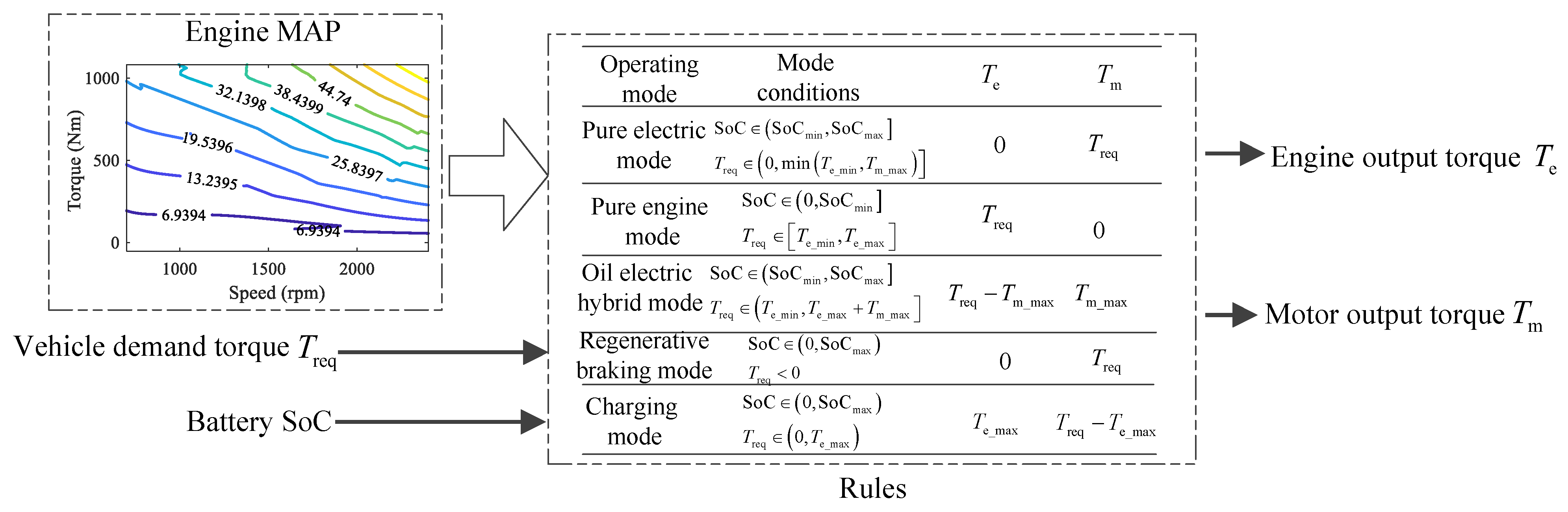
When formulating the rule base of deterministic RB EMSs, based on the historical working condition data and power system parameters of the vehicle, the rule parameters need to be calibrated offline, to adapt the corresponding vehicle system and working condition [55]. Taking the parallel oil–electric HL shown in Figure 7 as an example, the strategy design principle is presented in Figure 10.
As shown in Figure 10, is the total demand torque of the hydraulic system and drive assembly; and represent the minimum and maximum values of SoC, respectively; and show the upper and lower boundaries of the engine output torque; respectively; and and indicate the upper and lower boundaries of the motor output torque, respectively. It can be seen that, when the power system of HLs is determined, the boundary value of the power component can be determined. If and SoC of the current time are known, the working state of the engine and motor can be clarified. Then, the output torque combination of the engine and motor can be determined through the rule base shown in Figure 10 to realize the energy real-time management of the vehicle.
For example, Zhang et al. [9] analyzed the energy flow of the power system of HLs in cruise, loading, acceleration, and braking modes, and developed an RB EMS with demand torque, accumulator SoC, and vehicle speed as inputs, and motor torque and hydraulic pump torque as outputs. Compared with the pure-electric loader, this strategy can increase battery life by 15.64%. Bertini et al. [55] illustrated a dual-mode RB EMS for an oil–electric HL, which controlled the start–stop of the electric pump by judging the working state of the arm and the driving state of the vehicle. In comparison with the traditional loader, the fuel-saving rate of the strategy could be increased by 25%. Sun et al. [22] calculated the required torque and power of the system by judging the loading and shoveling state of the vehicle, and proposed a logic threshold control strategy based on the SoC size of the hydraulic accumulator. The energy recovery rate of the strategy could be achieved by 60.03% under typical working conditions. Wen et al. [24,25] designed an RB EMS in accordance with mixed weighting factors, which dynamically adjusted the working state of the engine via adjusting the factor K and selected the best working points of the engine by means of the engine MAP. Contrasted with the hydrostatic loader, this strategy saved fuel (18.9%) under short-cycle conditions. In [34], according to the relationship between the maximum output torque of the pump/motor and the system demand torque, a dynamic RB EMS was introduced, which took the real-time demand torque and the accumulator SoC as the inputs, and the torque of the engine and pump/motor as the outputs. This strategy could reduce fuel consumption by 13.5% compared with the traditional loaders, and improve the fuel-saving performance by 40.6% in comparison with the static logic threshold strategy.
Based on the analysis of the existing work, on the premise of following the energy balance principle, the design methods of rule base of deterministic RB EMSs are various, bringing different optimization effects. However, the advance determination of the rule base parameters not only limits the application object of the strategy, but also reduces the adaptability of the strategy to stochastic conditions. For this reason, researchers proposed fuzzy RB EMSs that do not depend on fixed parameters.
3.1.2. Fuzzy RB EMSs
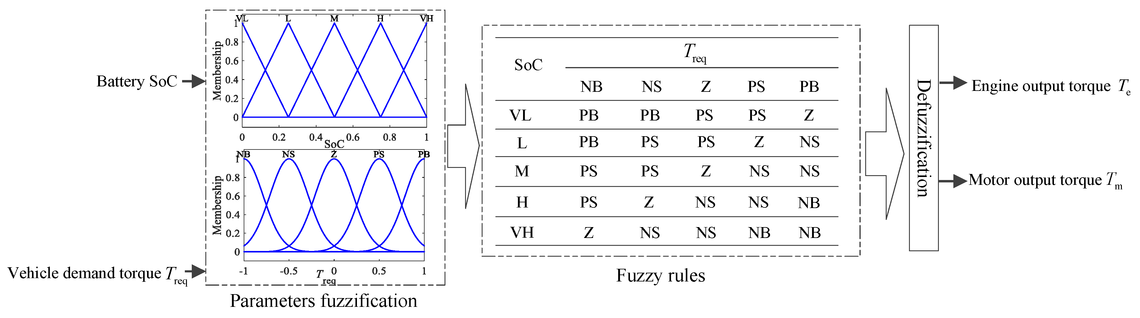
Fuzzy RB EMSs fuzzify the vehicle state and control variables, and the fuzzy rule base is formulated through the expert experience. The logical relationship of the rules no longer points to the specific parameters [56]. The fuzzy rule base not only improves the ability of the strategy to solve the energy consumption optimization problem of HLs, but also improves the adaptability of the strategy to heterogeneous vehicles and stochastic conditions. The implementation principle of the fuzzy RB EMSs corresponding to the strategy described in Figure 10 is shown in Figure 11.
Specifically, for the energy consumption problem of series and parallel oil–electric HLs, Zhao et al. [36,40] successively presented fuzzy RB EMSs, which fuzzified the demand torque, super capacitor SoC, and output torque of engine and motor. Contrasted with the traditional loader, under the same working condition, the fuel consumption of the developed strategies reduced by 16.6% and 7.8%, respectively. In [43], taking the parallel oil–electric HL as the object, the system demand torque and vehicle speed were obtained by online estimation. Then, a fuzzy RB EMS was proposed, which took the required torque, super capacitor SoC, vehicle speed, throttle opening, and hydraulic torque converter efficiency as inputs, and the engine operating point, motor operating point, and system gear as outputs. Compared with the traditional loader, it saved fuel (9.56%). Wang et al. [57] put forward a double fuzzy PID control method to identify and modify the unknown load and power parameters of the drive system, improving the efficiency of the power transmission system. In order to improve the optimization effect of fuzzy rule base, in [49], taking the demand power of the vehicle and SoC of the super capacitor as inputs and the system power of the fuel cell as the output, a fuzzy logic EMS was given. Then, the particle swarm optimization algorithm (PSOA) was used to optimize the membership function of the strategy, which made the average output power of the fuel cell decrease by about 5%. In [20], taking vehicle speed, SoC of energy storage system, and braking strength as input signals, and braking torque as the output signal, a combined braking control strategy on the basis of fuzzy control system was designed, which used genetic algorithm (GA) to optimize the optimal control rules of different working cycles offline. The experimental results showed that the strategy improved the recovery rate of braking energy under the premise of ensuring the safety and stability of the vehicle.
Fuzzy RB EMSs avoid the dependence on fixed parameters when designing strategies. In addition, the rule base of fuzzy RB EMSs is more suitable for different working scenarios with the assistance of artificial optimization algorithms (such as PSOA and GA), further improving the energy consumption optimization effect of the strategy. However, RB EMSs formulated by subjective experience limit the optimization effect of the strategy, especially for loaders with complex working conditions and random states. Therefore, researchers presented further OB EMSs.
3.2. OB EMSs
Different from RB EMSs, strictly taking the mathematical model of the HL optimization problem as the object, the OB EMSs solve the optimal control variable of the system by designing analytical algorithms from the perspective of system mechanism evolution. At present, according to the optimization degree and real-time performance of the strategy, the OB EMSs mainly involve global optimization EMSs and real-time optimization EMSs.
3.2.1. Global Optimization EMSs
The goal of global optimization EMSs is to achieve the global energy consumption optimization of the loaders in the whole operation process. Currently, considering the high nonlinearity of energy consumption optimization problem of HLs, the solution methods of its optimal strategy mainly include analytical and numerical methods. The analytical method is mainly represented by Pontryagin’s minimum principle (PMP) [58], and the numerical method is mainly represented by dynamic programming (DP) [59].
Using PMP to solve (2) needs to establish the Hamiltonian function of the problem in accordance with the system states and optimization objective,
namely, the solution of (2) is transformed into the extreme value solution of (3). Based on the PMP principle, combining and , using the co-state equation is to determine the value range of the co-state variable , to obtain the optimal control law , that is,
where the dimension of is the same to .
In [53], for the hydrogen fuel consumption problem of fuel cell HL, aiming at minimizing hydrogen fuel consumption was established with battery SoC as the state variable and output power of the fuel cell as the control variable. Its was optimized and selected under offline conditions to obtain optimal control law, optimizing the hydrogen consumption of the vehicle. In [54], taking the minimization of hydrogen fuel consumption and the durability of the fuel cell as the optimization objectives, a PMP EMS based on multi-objective optimization was introduced, which used offline working condition data to select the optimal value of . Under the premise of ensuring that SoC reached the target value, it achieved less hydrogen fuel consumption. For series oil–hydraulic HL, Zhang et al. [60] designed a PMP EMS, and compared its fuel consumption with a DP EMS and an RB EMS under long-load and short-load conditions. The results showed that the fuel consumption of the PMP EMS was close to that of the DP EMS, and less than that of the RB EMS, while significantly improving the strategy calculation. In [61], taking the energy consumption and battery life of HLs as optimization objects, the optimal strategy was solved by PMP. In order to realize the differentiability of to , the battery model was equivalently processed to obtain the value range of . The influence of different on energy consumption and battery life was also analyzed.
It can be seen that the core of using PMP to solve the energy consumption optimization problem is to find the appropriate , and the differentiability of to is the premise of solving . However, in the actual situation, because of the high nonlinearity of the state space equation of HLs, it is difficult to guarantee that to is always differentiable. Thus, the optimization problem usually needs to be equivalently processed, leading to the poor control effectiveness of the solved strategy on the actual system.
Different from PMP, DP does not need to consider whether the problem is differentiable when solving the energy consumption optimization problem of HLs. On the contrary, DP uses the Bellman optimality principle [59] to solve the optimal solution of the problem. The algorithm principle is as follows:
where describe the optimal value of from to time.
Specifically, in [62], considering the periodicity of the loader operation cycle, the HL operating condition curve in the spatial domain was built on the basis of historical data. The optimal strategy that could minimize the energy consumption and maximize the operating efficiency of the vehicle was solved by using DP. Wang et al. [32,33] used the transmission chain torque and hydraulic system torque obtained in advance to design a DP EMS offline. Compared with the RB EMS, the experiments showed that the DP EMS saved fuel (15% and 9.2% under long-load and short-load conditions, respectively). In [63], a DP EMS based on a fixed operation cycle was presented for the optimal energy efficiency of series and parallel oil–electric HLs. Contrasted with traditional loaders, the results showed that a DP EMS could improve the fuel efficiency of parallel HLs and series HLs by about 5% and 23%, respectively. UEBEL et al. [64] established the short-term loading condition and long-distance transportation condition curves of HL, and solved the optimal energy consumption strategy by using DP under the two conditions. The results indicated that, although the energy consumption optimization effect of the DP EMS was better than that of the RB EMS, it could not be applied in real-time. Mikko et al. [28] established a “Y” type operating cycle, and used DP to solve the energy consumption problem of HLs with three hybrid configurations. The experimental results showed that a DP EMS could save fuel (14–17%).
In summary, the solution of optimal value of PMP and the realization of the DP algorithm need to determine the global working condition information of loaders in advance. However, in the actual situation, although the loader operation has a strong periodicity, its state information is random and changeable. Therefore, it is difficult to obtain the future working condition information of the loaders accurately in advance, making the global optimization strategy difficult to be used directly for real-time optimization of the energy consumption, and can only be used to evaluate the energy consumption optimization effect of other strategies. For this reason, real-time optimization EMSs have been introduced.
3.2.2. Real-Time Optimization EMSs
Nowadays, considering both the real-time performance of strategy control and target optimization effect, the real-time optimization EMSs for HLs are mainly classified into instantaneous optimization EMSs and local optimal EMSs.
- Instantaneous optimization EMSs
Instantaneous optimization EMSs aim to achieve the optimal energy consumption of HLs in the current state. Currently, the equivalent consumption minimization strategy (ECMS) [8,65] is the most typical, and the corresponding problem model can be expressed as:
For further explanation, taking the parallel oil-electric hybrid configuration shown in Figure 7 as an example, will be expressed as:
where and represent the instantaneous fuel consumption of engine and the equivalent fuel of instantaneous power consumption of the battery, respectively; is a function of engine output torque and speed , directly related to engine power ; is a function of motor output torque and speed , directly related to battery power ; denotes the instantaneous efficiency of the engine; is the low calorific value of fuel; describes the equivalent factor between electric energy and fuel; and indicates a penalty factor, which generally changes with the change of battery SoC. Obviously, on the premise of given in advance, if the total demand torque and SoC at moment are determined, several torque combinations of engine and motor can be obtained, according to (7). On this basis, the optimal torque combination of the engine and motor that makes minimize at this time can be selected in accordance with (6). In other words, the key of the ECMS is to determine the appropriate .
Wen et al. [26] proposed an ECMS for an oil–hydraulic HL, which takes the equivalent fuel consumption as the optimization goal. The strategy utilized the average engine efficiency, hydraulic pump mechanical efficiency, and volume ratio to obtain a constant value . The simulation results showed that the fuel-saving rate of the ECMS was 5.4% higher than that of an RB EMS under the “V” operation cycle. Considering the repeatability of the working cycle of loaders, Wen et al. [27] continued to present an adaptive ECMS based on the working cycle. and were continuously updated by loop iteration to determine the optimal parameter combination that minimized the equivalent fuel consumption. The results indicated that the fuel-saving rate of the strategy was 3.69~6.36% higher than that of the ECMS with fixed . In addition, when , the solution process of PMP was similar to the solution process of ECMS. For this reason, Iman et al. [66] used the analytical idea of PMP to solve . In order to ensure the adaptability of to different working conditions, an calculation method for four working conditions was designed. On the premise of ensuring the effect of energy consumption optimization, the designed adaptive ECMS increased the calculation speed by 43 times, contrasted with the standard ECMS, which was more suitable for the actual working condition.
In comparison with a fixed , changing with the working condition is easier to improve the optimization effect and working condition adaptability of ECMS. However, the ECMS only considers instantaneous energy consumption optimization and does not consider future energy consumption optimization, limiting the global optimization effect of energy consumption. Therefore, researchers have introduced local optimal EMSs represented by MPC.
- 2.
- Local optimal EMSs
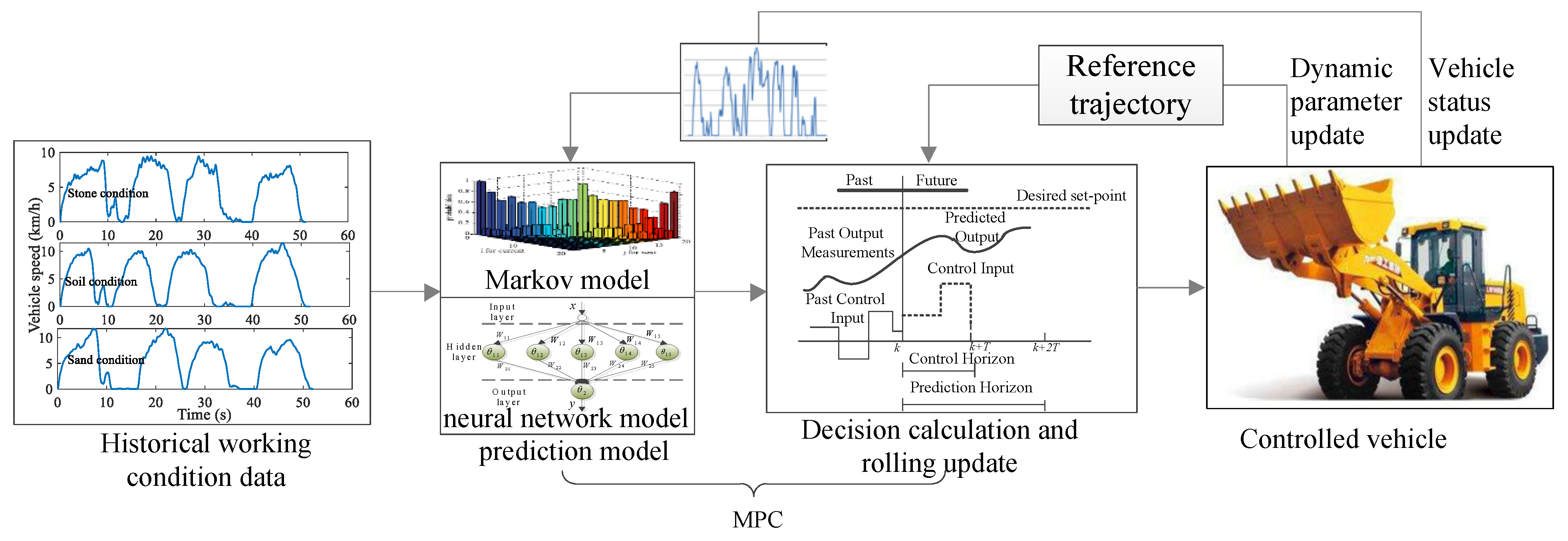
As mentioned above, obtaining the working condition information in advance is very important to improve the energy consumption optimization performance of EMSs. MPC with a rolling optimization mechanism provides an effective way to solve this problem [67]. The core idea of MPC is to transform the global energy consumption optimization problem of HLs into a local energy consumption optimization problem, and approximates the global optimal solution of energy consumption by means of an online rolling solution. The key steps of the process are information rolling prediction and a local optimal solution. The principle is shown in Figure 12, and the corresponding problem model is as follows:
where indicates the prediction window size, which can represent the spatial position or the time point.
In [8], the Levenberg–Marquardt neural network was used to establish the demand power prediction model of HL, and then the MPC EMS was designed by using the predicted power sequence. Nilsson et al. [38] presented an MPC EMS based on stochastic DP for HL. Firstly, the strategy found the optimal control variable and energy consumption corresponding to each state through an iterative algorithm offline, forming the MAP relationship between the load and optimal control variable. Then, the probability matrix that the demand power evolves with distance was built. Finally, the optimal control variable was estimated online using the matrix according to the real-time demand power, realizing the optimization effect of saving fuel by 3–4% compared with the non-prediction strategy. In [50], considering the operation repeatability and working condition randomness of loaders, an MPC EMS was designed by using the Markov chain and neural network, which used offline data to establish the Markov probability transfer matrix and neural network prediction model of demand power, respectively. Then, taking each future operation cycle of the vehicle as the window, the demand power sequence was predicted in a rolling way. Finally, the DP algorithm was used to obtain the local optimal solution of each window. The simulation results show that the difference of the prediction window size can directly influence the optimization effect of the MPC. The larger the size is, the better the optimization effect of energy consumption is, but the amount of calculation increases. On the contrary, the energy consumption effect is worse and the real-time performance is better. In [51], a hierarchical predictive control strategy was proposed, which used wavelet transformation to decompose the load signal into low-frequency and high-frequency signals. Then, taking different frequency signals as the input data of the neural network, the wavelet transformation was used again to reconstruct and synthesize the frequency data predicted by the neural network to obtain the future demand power of HL. Finally, the DP algorithm was used to obtain the optimal control variable. In [52], considering the fuel economy, fuel cell stability, and battery life of the fuel cell HL, an MPC EMS on the basis of multi-objective optimization was designed. The strategy used a three-layer Elman neural network to predict the demand power sequence of HLs online, and utilized the adaptive weight method based on fuzzy logic algorithm to allocate the weight of each optimization target, converting the multi-objective problem into a single-objective problem.
It can be seen that an MPC EMS can realize the closed-loop control of vehicle energy consumption through rolling optimization, and improve the energy consumption optimization effect of EMSs for different HL configurations and different working conditions through dynamic adjustment of target error. In this process, the MPC EMS needs to ensure the rationality of prediction window size selection, the accuracy of information prediction, and the real-time performance of algorithm calculation.
3.3. Simulation Analysis of EMSs
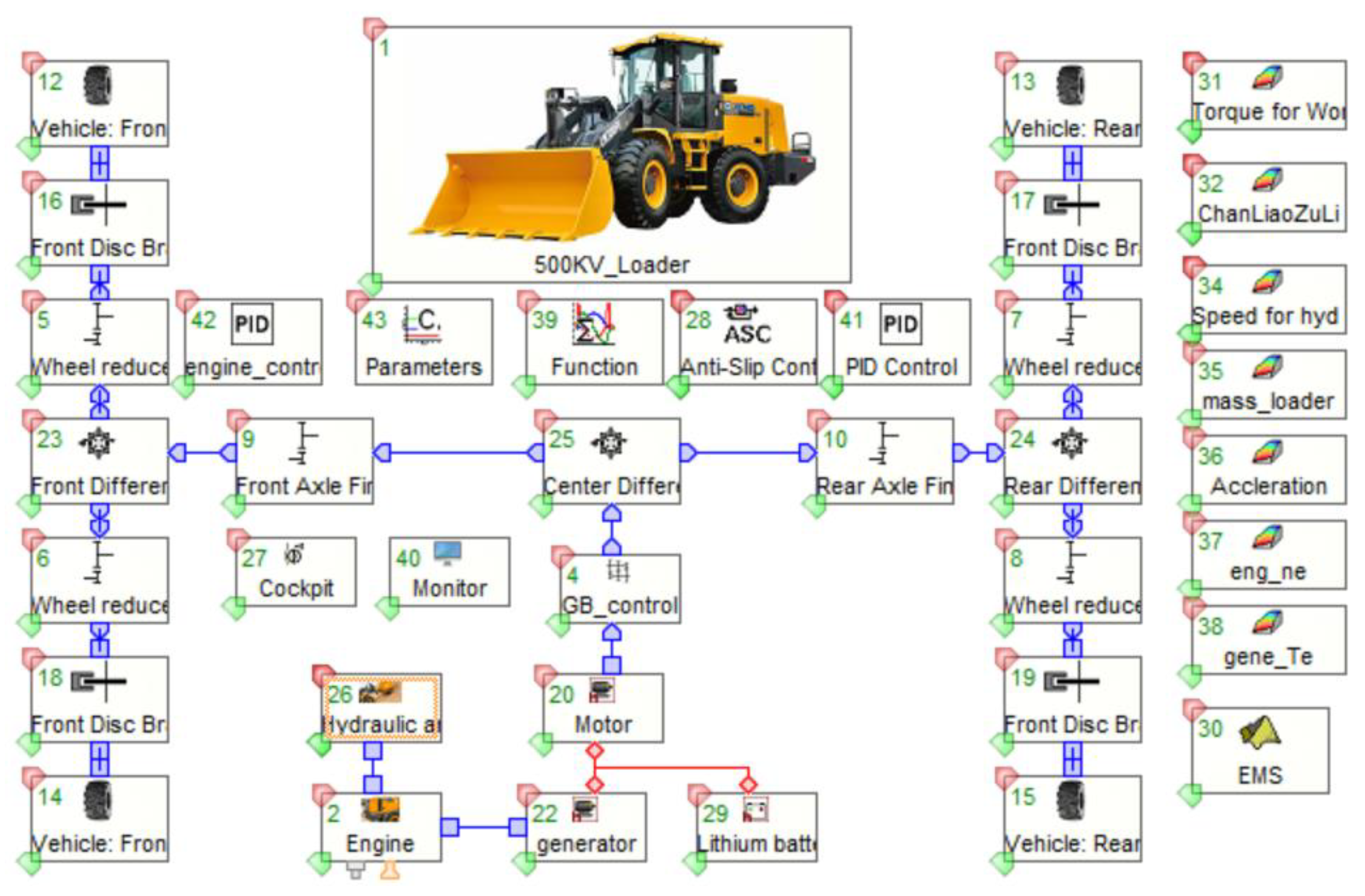
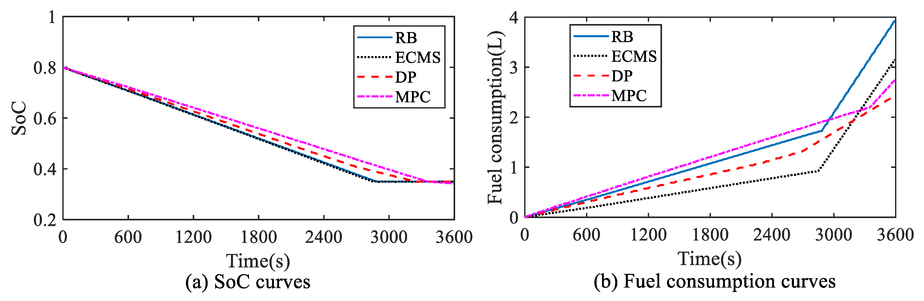
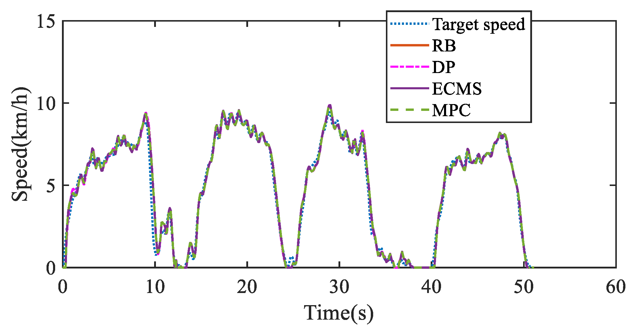
Based on above comparative analysis, taking a series oil–electric HL as an example, the energy optimization effect of the RB, ECMS, DP, and MPC EMSs are compared and analyzed. Correspondingly, the system model of HLs established by CRUISE software is shown in Figure 13. The energy consumption of four EMSs is shown in Figure 14 under 70 “V” cycles. The vehicle speed following effect of four EMSs under 1 “V” cycle is presented in Figure 15.
As shown in Figure 14 and Figure 15, under the premise of ensuring the speed following effect, although the SoC thresholds of the four EMSs can reach the expected 0.3, their fuel consumption is different due to different optimization methods. The corresponding cumulative fuel consumption of the four EMSs is listed in Table 2. It can be seen that the fuel consumption of the DP EMS is the smallest among them, but the simulation time is the longest. In addition, although the fuel consumption of the MPC EMS is higher than that of the DP EMS by 12.8%, on the premise of ensuring real-time performance, its fuel consumption reduces by 30.4% and 13.3% compared with the RB EMSs and ECMS, respectively.
4. Discussion and Analysis
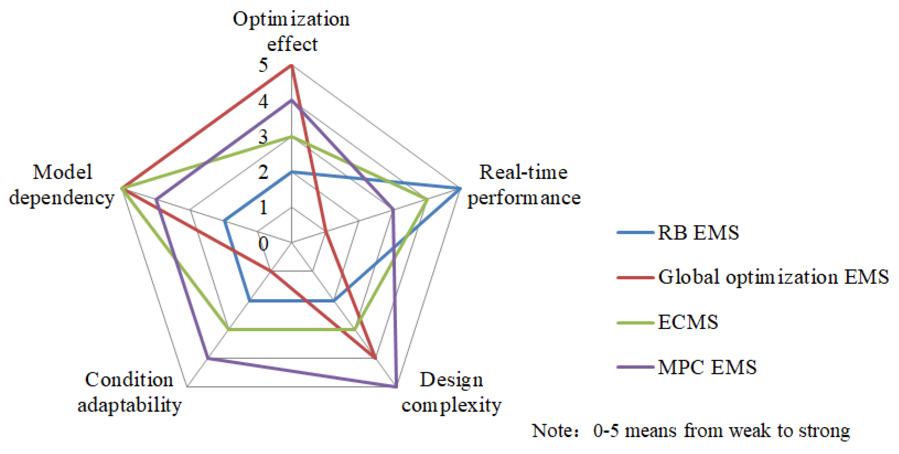
In summary, the differences in EMS design ideas make their energy consumption optimization effect different, as shown in Figure 16. Firstly, although the global optimization EMSs can achieve the optimal control of energy consumption of HLs, their dependence on global information makes it difficult to be directly applied online. Secondly, on the premise of ensuring real-time performance, an ECMS can achieve a better energy consumption optimization effect than an RB EMSs by finding a reasonable equivalent factor, but the design of the latter is more simple and direct, making engineering application easier. Thirdly, compared with an ECMS, an MPC EMS further improves the optimization performance of the strategy, especially enhancing the adaptability of the strategy to stochastic conditions. Theoretically, an MPC EMS is more suitable for heterogeneous HLs, but its design process is more complex than an ECMS, and it requires sufficient hardware resources for computing support. Meanwhile, contrasted with an RB EMS, the accuracy of the system model directly affects the accuracy of an OB EMS on actual vehicle control.
In addition, with the electric technology continuously promoting the diversified development of HL configurations and the continuous complexity of HL operation scenarios, higher requirements are put forward for energy-saving level and robustness of optimization effects of EMSs. Therefore, the research of EMSs for HLs still faces the following challenges.
- A single strategy not ensuring the optimization effect and real-time performance simultaneously
The operating condition randomness and scenarios diversity of HLs make it difficult to take into account the optimality and real-time performance of the strategy when a single strategy is used for energy optimization. Therefore, it is necessary to integrate the advantages of multiple strategies and explore the complementary advantages between strategies. Namely, the study of EMSs based on multi-method fusion will provide a new idea to solve this problem.
- 2.
- Dependence on the analytical model weakening the universality of the strategy
With the increasing complexity of HL configurations and degree of electromechanical–hydraulic coupling, the universality of EMSs established in accordance with the system mechanism model will be challenged, especially the tolerance of strategy to the uncertainty of vehicle state evolution caused by system interference. Considering that intelligent control [68] can perform approximate optimal control on systems without mechanism models, developing an intelligent EMS not depending on the system mechanism model will provide a new way to meet the above challenges.
Therefore, in view of the periodicity and repeatability of the working condition of the loaders, intelligent control is used to conduct reinforcement learning (RL) on the operation behavior of HLs. By means of the optimal control idea, the optimization effect of the control strategy is continuously adjusted, to make it continuously approximate the optimal solution of the energy consumption problem. In other words, it will be inevitable to develop an intelligent EMS independent of the HL mechanism model by combining the RL ability of intelligent control with the optimal control idea.
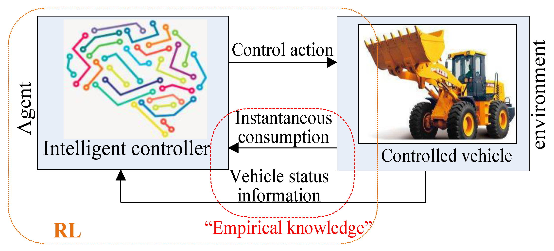
The process of intelligent EMSs to achieve energy optimization control is actually the process of agent RL [69,70]. That is, after the control system (regarded as an agent) applies control to the controlled vehicle (regarded as an environment), it is always hoped that the state evaluation and process consumption of the vehicle feedback are better. In addition, the parameters of the control system are continuously adjusted to make the process approach optimization continuously. Therefore, the optimization effect of intelligent EMSs mainly depends on the empirical knowledge and learning methods of control system parameters, not directly related to the internal mechanism of the controlled object. The optimization idea is shown in Figure 17, and the corresponding optimization problem model is as follows:
where represents the optimal energy consumption approximation of the system from time to time, that is, the estimated value of ; and is a discount factor.
At present, for hybrid electric vehicles, some researchers have conducted a preliminary study on intelligent EMSs. For example, in [71,72,73], the EMS was designed by the Q-learning method, which continuously evaluated the system state feedback and energy consumption optimization effect, and dynamically adjusted the parameters of the strategy model to improve its adaptability to the general working condition. In addition, considering the heuristic dynamic programming (HDP) [68] in intelligent control, combining the ideas of DP and RL, LI et al. [74] proposed an adaptive loop control algorithm based on execution-dependent HDP. On the basis of this, an adaptive EMS was designed, and its energy consumption optimization effect was very close to DP. In [75], a HDP controller according to a back propagation neural network was given. While meeting the fuel economy of the vehicle, the controller could make the power of the energy storage device change smoothly and prolong the life of the energy storage device.
It can be seen that the feasibility of intelligent EMSs has been preliminarily verified in the study of energy consumption optimization of hybrid electric vehicles, which will provide an effective theoretical support for EMSs research of HLs.
5. Conclusions
In this paper, the application, development, and prospects of EMSs for HLs are presented. Firstly, on the basis of the analysis of the working condition of the loaders, the configurations of HLs are classified, and the characteristics and research status of each configuration are analyzed. Then, considering the particularity of loader operation, the EMSs for HLs are classified, and the design principle and research status of various strategies are explained. Based on the comprehensive comparison of the characteristics of existing EMSs, the development trend and challenges of EMSs for HLs are discussed. Finally, the prospective research direction of EMSs is considered in combination with the development trend of HL. The conclusions are as follows:
(1) Although the existing EMSs can effectively optimize the energy consumption of HLs, the dependence of the strategy on the mechanism model and the vehicle parameters will reduce the applicability of the strategy to heterogeneous HLs, and the robustness to a complex working condition.
(2) Combining the advantages of intelligent control and optimal control, designing an intelligent EMS that does not depend on the vehicle analytical model will provide a new universal solution for solving the energy consumption optimization problem of HLs.
Author Contributions
J.L. and Y.L. conceived and completed the paper writing. Z.C. made key modifications to important knowledge parts. W.C. discussed the configurations of HLs and collected the related data. All authors have read and agreed to the published version of the manuscript.
Funding
This research was supported by Young Scientists Fund of the National Natural Science Foundation of China (Grant No. 62103415).
Data Availability Statement
The data presented in this study are available on request from the corresponding author. The data are not publicly available due to the supporting project has a confidentiality agreement.
Acknowledgments
The authors would like to thank the editor and reviewers for their valuable comments and suggestions, which helped them improve the manuscript.
Conflicts of Interest
The authors declare no competing financial interest.
Nomenclature
| Abbreviations | |
| EMS | energy management strategy |
| HLs | hybrid loaders |
| ERS | energy regeneration system |
| DC | direct current |
| MPC | |
| model predictive control | |
| SoC | state of charge |
| RB | rule-based |
| OB | optimization-based |
| PSOA | particle swarm optimization algorithm |
| GA | genetic algorithm |
| PMP | Pontryagin’s minimum principle |
| DP | dynamic programming |
| ECMS | equivalent consumption minimization strategy |
| RL | reinforcement learning |
| HDP | heuristic dynamic programming |
| Variables and parameters | |
| output power of the power source | |
| output torque of the power source | |
| output speed of the power source | |
| power of wheel | |
| torque of wheel | |
| speed of wheel | |
| driving force of wheel | |
| vehicle speed | |
| power of hydraulic system | |
| torque of hydraulic system | |
| speed of hydraulic system | |
| displacement of hydraulic system | |
| pressure of hydraulic system | |
| energy transmission efficiency between the wheel and power source | |
| energy transmission efficiency between the hydraulic pump and power source | |
| discrete time or distance point | |
| performance index of HLs | |
| cost function | |
| state variables set of HLs | |
| control variables set of the drive system | |
| state space equation of HLs system | |
| constraint conditions of | |
| control variables set of allowable input of | |
| total demand torque of the hydraulic system and drive assembly | |
| minimum value of SoC | |
| maximum value of SoC | |
| lower boundaries of the engine output torque | |
| upper boundaries of the engine output torque | |
| lower boundaries of the motor output torque | |
| upper boundaries of the motor output torque | |
| Hamiltonian function | |
| co-state variable | |
| optimal control law | |
| optimal value of from to time | |
| instantaneous fuel consumption of engine | |
| equivalent fuel of instantaneous power consumption of the battery | |
| engine output torque | |
| engine output speed | |
| engine power | |
| motor output torque | |
| motor output speed | |
| battery power | |
| instantaneous efficiency of the engine | |
| low calorific value of fuel | |
| equivalent factor between electric energy and fuel | |
| penalty factor | |
| prediction window size | |
| probability matrix | |
| demand power | |
| distance | |
| optimal energy consumption approximation of the system | |
| a discount factor |
References
- Tong, Z.; Miao, J.; Li, Y.; Tong, S.; Zhang, Q.; Tan, G. Development of electric construction machinery in China: A review of key technologies and future directions. J. Zhejiang Univ. Sci. A 2021, 22, 245–264. [Google Scholar] [CrossRef]
- Verma, S.; Mishra, S.; Gaur, A.; Chowdhury, S.; Mohapatra, S.; Dwivedi, G. A comprehensive review on energy storage in hybrid electric vehicle. J. Traffic Transp. Eng. Engl. Ed. 2021, 8, 621–637. [Google Scholar] [CrossRef]
- Wang, J.; Yang, Z.; Liu, S.; Zhang, Q.; Han, Y. A Comprehensive overview of hybrid construction machinery. Adv. Mech. Eng. 2016, 8, 1–15. [Google Scholar] [CrossRef] [Green Version]
- Wang, Y.; Zhao, D.; Wang, Z.; Hu, Y. The trend and actuality of hybrid power loaders. Key Eng. Mater. 2014, 621, 649–654. [Google Scholar] [CrossRef]
- He, X.; Jiang, Y. Review of hybrid electric systems for construction machinery. Autom. Constr. 2018, 92, 286–296. [Google Scholar] [CrossRef]
- Zhang, W.; Wang, J.; Du, S.; Ma, H.; Zhao, W.; Li, H. Energy management strategies for hybrid construction machinery: Evolution, classification, comparison and future trends. Energies 2019, 12, 2024. [Google Scholar] [CrossRef] [Green Version]
- Yang, J.; Bian, Y.; Yang, M.; Shao, J.; Liang, A. Parameter Matching of Energy Regeneration System for Parallel Hydraulic Hybrid Loader. Energies 2021, 14, 5014. [Google Scholar] [CrossRef]
- Liu, H.; Li, T. Energy Management strategy development for fuel cell hybrid loaders. IOP Publishing Ltd. In Proceedings of the International Conference on Civil and Hydraulic Engineering, Qingdao, China, 23–25 November 2018; Volume 189, p. 052015. [Google Scholar]
- Zhang, H.; Wang, F.; Xu, B.; Fiebig, W. Extending battery lifetime for electric wheel loaders with electric-hydraulic hybrid powertrain. Energy 2022, 261, 125190. [Google Scholar] [CrossRef]
- K-Series Loaders 644K/724K. Available online: https://www.deere.com/assets/publications/index.html?id=d861a139#1 (accessed on 17 March 2019).
- K-Series 944K Wheel Loader—A Hybrid of Epic Innovations. Available online: http://docplayer.net/77232251-K-series-944k-wheel-loader-a-hybrid-of-epic-innovations.html (accessed on 17 March 2019).
- Ishida, K.; Higurashi, M. Hybrid Wheel Loaders Incorporating Power Electronics. Hitachi Rev. 2015, 64, 398–402. [Google Scholar]
- Tianyu, L.I.; Dingxuan, Z.H.O.; Huailiang, K.A.G.; Zhiwen, Z.H.N.; Zhengfei, Z.H.N.; Chunbo, X.U. Parameter matching of parallel hybrid power loaders. J. Jilin Univ. Eng. Ed. 2013, 43, 916–921. [Google Scholar]
- XC9350 Ultra-Large Tonnage Electric Drive Loader of XCMG. Available online: https://mproduct.cmo2o.com/zhuangzaiji/xcmg/xc9350/ (accessed on 17 March 2019).
- 862H Wheel Loader. Available online: https://www.liugong.com/en/Product/Machines/Wheel-Loaders/862H (accessed on 17 March 2019).
- Kawasaki Launched Hybrid Loader 65Z in Conexpo. Available online: https://www.cehome.com/news/20110326/10612.shtml (accessed on 17 March 2019).
- Lyu, C.; Yanqing, Z.; Meng, L. Loader power-split transmission system based on a planetary gear set. Adv. Mech. Eng. 2018, 10, 1–8. [Google Scholar] [CrossRef] [Green Version]
- Zou, N.W.; Dai, Q.L.; Jia, Y.H.; Zhang, W.; Ren, Y.C. Modeling and Simulation Research of Coaxial Parallel Hybrid Loader. Appl. Mech. Mater. 2010, 29–32, 1634–1639. [Google Scholar]
- Zhenbao, W.A.G.; Sicheng, Q.I. Analysis of dynamic characteristics of hydraulic torque converter of loader. J. South China Univ. Technol. Nat. Sci. Ed. 2016, 44, 41–46. [Google Scholar]
- Lin, M.; Yu, Z.; Zhao, L.; Chen, Y. Working cycle identification–based braking control strategy and its application for hydraulic hybrid loader. Adv. Mech. Eng. 2018, 10, 1–12. [Google Scholar] [CrossRef]
- Lai, X.; Guan, C. A parameter matching method of the parallel hydraulic hybrid excavator optimized with genetic algorithm. Math. Probl. Eng. 2013, 2013, 765027. [Google Scholar] [CrossRef] [Green Version]
- Sun, H.; Jing, J. Research on the system configuration and energy control strategy for parallel hydraulic hybrid loader. Autom. Constr. 2010, 19, 213–220. [Google Scholar]
- Du, Z.; Kai, L.C.; Li, P.Y.; Chase, T. Fuel economy comparision of series, parallel and HMT hydraulic hybrid architectures. In Proceedings of the American Control Conference (ACC), Washington, DC, USA, 1 June 2013; IEEE; pp. 5954–5959. [Google Scholar]
- Wen, Q.; Wang, F.; Xu, B. Modeling and design of a series hydraulic hybrid powertrain for compact wheel loaders. American Society of Mechanical Engineers. In Proceedings of the BATH/ASME Symposium on Fluid Power and Motion Control, Bath, UK, 12–14 September 2018; pp. 1–9. [Google Scholar]
- Wen, Q.; Wang, F.; Xu, B.; Sun, Z. Improving the fuel efficiency of compact wheel loader with a series hydraulic hybrid powertrain. IEEE Trans. Veh. Technol. 2020, 69, 10700–10709. [Google Scholar] [CrossRef]
- Qunya, W.E.; Feng, W.A.G.; Bing, X.U.; Zongxuan, S.U. Power optimization of series hydraulic hybrid powertrain for compact wheel loader. American Society of Mechanical Engineers. In Proceedings of the ASME/BATH 2019 Symposium on Fluid Power and Motion Control, Longboat Key, FL, USA, 7–9 October 2019. [Google Scholar]
- Qunya, W.E.; Feng, W.A.G.; Min, C.H.N.; Bing, X.U.; Zongxuan, S.U. Adaptive Equivalent Consumption Minimization Strategy for Off-Road Hydraulic Hybrid Vehicles: A Cycle-to-Cycle Optimization Approach. IEEE Trans. Veh. Technol. 2022, 71, 2346–2357. [Google Scholar]
- Mikko, H.; Mikko, H.; Jyrki, T.; Matti, L.; Jussi, T. Fuel efficiency optimization of a baseline wheel loader and its hydraulic hybrid variants using dynamic programming. In Proceedings of the BATH/ASME Symposium on Fluid Power and Motion Control, Bath, UK, 12–14 September 2018. [Google Scholar]
- Pengyu, Z.H.O.; Yinglong, C.H.N.; Hua, Z.H.U. Summary of research on the system and control strategy of hydraulic hybrid engineering machinery. J. Zhejiang Univ. Eng. Ed. 2016, 50, 11. [Google Scholar]
- Yan, L.; Sun, H.; Liu, W.; Jiang, J.; Zhao, Y.; Han, J. Hydraulic hybrid technology of moving construction machinery. J. Jilin Univ. Eng. Ed. 2014, 44, 364–368. [Google Scholar]
- Rongling, S.H.; Hui, S.U. Analysis and optimization of energy saving factors of hydraulic hybrid wheel loader. Agric. Mach. J. 2011, 42, 31–35. [Google Scholar]
- Wang, F.; Zulkefli, M.A.M.; Sun, Z.; Stelson, K.A. Investigation on the energy management strategy for hydraulic hybrid wheel loaders. American Society of Mechanical Engineers. In Proceedings of the ASME Dynamic Systems and Control Conference, virtual, 5–7 October 2013. [Google Scholar]
- Wang, F.; Zulkefli, M.A.M.; Sun, Z.; Stelson, K.A. Energy management strategy for a power-split hydraulic hybrid wheel loader. Proc. Inst. Mech. Eng. Part D J. Automob. Eng. 2016, 230, 1105–1120. [Google Scholar] [CrossRef]
- Yang, J.; Bian, Y.; Liu, G.; Ji, P.; Chen, Q. Development of a parallel hydraulic hybrid loader through modeling. IOP Publishing Ltd. In Proceedings of the International Conference on Design, Mechanical and Material Engineering (D2ME), Busan, South Korea, 26–28 September 2019; Volume 686, p. 012007. [Google Scholar]
- Hoai-An, T.; Hoai, V.A.T.; Tri, C.D.; Manh, H.N.; Van, D.P.; Kyoung, K.A. Optimization-based energy management strategies for hybrid construction machinery: A review. Energy Rep. 2022, 8, 6035–6057. [Google Scholar]
- Zhao, D.; Zhang, Z.; Li, T.; Lan, H.; Zhang, M.; Dong, Y. Fuzzy logic control strategy of series hybrid power loader. J. Jilin Univ. Eng. Technol. Ed. 2014, 44, 1334–1341. [Google Scholar]
- Stein, G.; Froberg, A.; Martinsson, J.; Brattberg, B.; Filla, R.; Unnebäck, J. Fuel efficiency in construction equipment-optimize the machine as one system. In Proceedings of the AVL International Commercial Powertrain Conference, Graz, Austria, 21–23 May 2013. [Google Scholar]
- Nilsson, T.; Froberg, A.; Aslund, J. Predictive control of a diesel electric wheel loader powertrain. Control. Eng. Pract. 2015, 41, 47–56. [Google Scholar] [CrossRef]
- Lin, Z.; Wang, F.; Xu, B. Improving wheel loader energy efficiency with a series electric hybrid powertrain. In Proceedings of the BATH/ASME 2022 Symposium on Fluid Power and Motion Control, Bath, UK, 14–16 September 2022. [Google Scholar]
- Dingxuan, Z.H.O.; Zhiwen, Z.H.N.; Tianyu, L.I.; Min, Z.H.N.; Yan, D.O.G.; Hao, L.A. Fuzzy logic control strategy of parallel hybrid power loader. J. Jilin Univ. Eng. Technol. Ed. 2014, 44, 1004–1009. [Google Scholar]
- Zhao, D.; Zhang, Z.; LI, M.; Li, T.; Wang, C. Research on control strategy for parallel hybrid loader. In Proceedings of the IEEE 3rd International Conference on Information Science and Technology, Yangzhou, China, 23–25 March 2013; pp. 275–279. [Google Scholar]
- Li, T.; Liu, H.; Zhang, Z.; Ding, D. Shift scheduling strategy development for parallel hybrid construction vehicles. J. Cent. South Univ. 2019, 26, 587–603. [Google Scholar] [CrossRef]
- Zhiwen, Z.H.N.; Dingxuan, Z.H.O.; Tianyu, L.I.; Min, Z.H.N. Control strategy based on automatic transmission for hybrid loader. J. Northeast. Univ. Nat. Sci. 2015, 36, 532–536. [Google Scholar]
- Dingxuan, Z.H.O.; Tianyu, L.I.; Huailiang, K.A.G.; Zhiwen, Z.H.N.; Mufei, L.I. Automatic shift technology of hybrid power engineering vehicle. J. Jilin Univ. Eng. Ed. 2014, 44, 358–363. [Google Scholar]
- Sergio, G.; Andera, B.; Ettore, C. A series-parallel hybrid electric powertrain for industrial vehicles. In Proceedings of the IEEE Vehicle Power and Propulsion Conference, Hanoi, Vietnam, 14–17 October 2010; p. 5729045. [Google Scholar]
- Liu, J.; Peng, H.; Filipi, Z. Modeling and analysis of the Toyota Hybrid System. In Proceedings of the IEEE/ASME International Conference on Advanced Intelligent Mechatronics, Monterey, CA, USA, 27 June–1 July 2005. [Google Scholar]
- Liu, J.; Peng, H. Control optimization for a power-split hybrid vehicle. In Proceedings of the American Control Conference, Minneapolis, MN, USA, 14-16 June 2006. [Google Scholar]
- Yin, X.U.; Dong, C.H.N. A new parallel-series hybrid electric car’s driving system. Automot. Eng. 2010, 32, 501–504. [Google Scholar]
- Zhiwen, Z.H.N.; Wenjie, D.U.; Junfei, L.I.N.; Yangang, Z.H.N.; Yawen, W.U. Hierarchical control of composite power loader based on fuel cell. J. Beijing Univ. Aeronaut. Astronaut. 2022, 48, 2165–2176. [Google Scholar]
- Li, T.; Liu, H.; Ding, D. Predictive energy management of fuel cell supercapacitor hybrid construction equipment. Energy 2018, 149, 718–729. [Google Scholar] [CrossRef]
- Li, T.; Liu, H.; Wang, H.; Yao, Y. Hierarchical predictive control-based economic energy management for fuel cell hybrid construction vehicles. Energy 2020, 198, 117327. [Google Scholar] [CrossRef]
- Li, T.; Liu, H.; Wang, H.; Yao, Y. Multi objective Optimal Predictive Energy Management for Fuel Cell/Battery Hybrid Construction Vehicles. IEEE Access 2020, 8, 25927–25937. [Google Scholar] [CrossRef]
- Hong, Z.; Li, Q.; Chen, W. An energy management strategy based on PMP for the fuel cell hybrid system of locomotive. Proc. CSEE 2019, 39, 3867–3879. [Google Scholar]
- Xiang, M.E.G.; Qi, L.I.; Weirong, C.H.N.; Guorui, Z.H.N. An energy management method based on Pontryagin minimum principle satisfactory optimization for fuel cell hybrid systems. Proc. CSEE 2019, 39, 782–792+957. [Google Scholar]
- Bertini, A.; Ceraolo, M.; Lutzemberger, G. Systematic approach in the hybridization of a hydraulic skid loader. Autom. Constr. 2015, 58, 144–154. [Google Scholar] [CrossRef]
- Luo, P.; Lin, M.; Chen, Y.; Zhao, L.; Ma, B. Energy management strategy for hybrid engineering vehicles with composite energy storage. Lect. Notes Electr. Eng. 2019, 503, 147–156. [Google Scholar]
- Wang, H.; Yang, S.; Lu, T. Mechanical transmission system of loader based on hydraulic hybrid technology. Therm. Sci. 2021, 26, 4233–4240. [Google Scholar] [CrossRef]
- Pontryagin, L.; Boltyanskii, V.; Gamkrelidze, R.; Mishchenko, E. The Mathematical Theory of Optimal Processes; Inderscience Publishers: New York, NY, USA, 1962. [Google Scholar]
- Dimitri, P.; Bertsekas. Dynamic Programming and Optimal Control; Athena Scientific: Belmont, Japan, 1995. [Google Scholar]
- Zhang, Q.; Wang, F.; Xu, B.; Sun, Z. Online optimization of Pontryagin’s minimum principle for a series hydraulic hybrid wheel loader. Proc. Inst. Mech. Eng. Part D J. Automob. Eng. 2022, 236, 1487–1499. [Google Scholar] [CrossRef]
- Iman, S.; Jan, Å. Energy management of hybrid electric vehicles with battery aging considerations: Wheel loader case study. Control. Eng. Pract. 2021, 110, 104759. [Google Scholar]
- Antti, L. Development of energy management strategies for heavy mobile machinery. American Society of Mechanical Engineers. In Proceedings of the ASME Dynamic Systems and Control Conference, Palo Alto, CA, USA, 21–23 October 2013. [Google Scholar]
- Frank, B. Using optimal control in concept evaluation and system optimization of diesel-electric hybrid construction machines. Institute of Electrical and Electronics Engineers Inc. In Proceedings of the International Conference on Electrical Systems for Aircraft, Railway, Ship Propulsion and Road Vehicles/International Transportation Electrification Conference, Toulouse, France, 2–4 November 2016; p. 7841323. [Google Scholar]
- Uebel, K.; Raduenz, H.; Krus, P.; De Negri, V.J. Design optimisation strategies for a hydraulic hybrid wheel loader. In Proceedings of the BATH/ASME Symposium on Fluid Power and Motion Control, Bath, UK, 12–14 September 2018. [Google Scholar]
- Zeng, X.; Bai, G.; Wang, J.; Zhou, Z. The instantaneous optimal control strategy of parallel hybrid loader. Appl. Mech. Mater. 2013, 380–384, 467–471. [Google Scholar] [CrossRef]
- Shafikhani, I.; Åslund, J. Analytical Solution to Equivalent Consumption Minimization Strategy for Series Hybrid Electric Vehicles. IEEE Trans. Veh. Technol. 2021, 70, 2124–2137. [Google Scholar] [CrossRef]
- Zhang, F.; Hu, X.; Xu, K.; Tang, X.; Cui, Y. Current status and prospects for model predictive energy management in hybrid electric vehicles. J. Mech. Eng. 2019, 55, 86–108. [Google Scholar] [CrossRef] [Green Version]
- Liu, D.; Xue, S.; Zhao, B.; Luo, B.; Wei, Q. Adaptive dynamic programming for control: A survey and recent advances. IEEE Trans. Syst. Man Cybern. Syst. 2021, 51, 142–160. [Google Scholar] [CrossRef]
- Qi, X.; Wu, G.; Boriboonsomsin, K.; Barth, M.J.; Gonder, J. Data-driven reinforcement learning-based real-time energy management system for plug-in hybrid electric vehicles. Transp. Res. Rec. 2016, 2572, 1–8. [Google Scholar] [CrossRef] [Green Version]
- Wu, Y.K.; Tan, H.C.; Peng, J.K.; Zhang, H.L.; He, H.W. Deep reinforcement learning of energy management with continuous control strategy and traffic information for a series-parallel plug-in hybrid electric bus. Appl. Energy 2019, 247, 454–466. [Google Scholar] [CrossRef]
- Wu, J.; He, H.; Peng, J.; Li, Y.; Li, Z. Continuous reinforcement learning of energy management with deep Q network for a power split hybrid electric bus. Appl. Energy 2018, 222, 799–811. [Google Scholar] [CrossRef]
- Zhang, W.; Wang, J.; Liu, Y.; Gao, G.; Liang, S.; Ma, H. Reinforcement learning-based intelligent energy management architecture for hybrid construction machinery. Appl. Energy 2020, 275, 115401. [Google Scholar] [CrossRef]
- Zhu, Q.; Wang, Q. Real-time energy management controller design for a hybrid excavator using reinforcement learning. J. Zhejiang Univ. -SCIENCE A Appl. Phys. Eng. 2017, 18, 855–870. [Google Scholar] [CrossRef]
- Li, G.; Gorges, D. Ecological adaptive cruise control and energy management strategy for hybrid electric vehicles based on heuristic dynamic programming. IEEE Trans. Intell. Transp. Syst. 2019, 20, 3526–3535. [Google Scholar] [CrossRef]
- Liu, J.; Chen, Y.; Zhan, J.; Shang, F. Heuristic dynamic programming based online energy management strategy for plug-in hybrid electric vehicles. IEEE Trans. Veh. Technol. 2019, 68, 4479–4493. [Google Scholar] [CrossRef]
Figure 1.
The drivetrain configuration of a traditional loader.

Figure 2.
Typical operation cycle schematic diagram of a loader.

Figure 3.
Operation characteristics of a loader under “V” cycle.


Figure 6.
Typical configuration of series oil–electric hybrid system [36].
Figure 6.
Typical configuration of series oil–electric hybrid system [36].


Figure 8.
Typical configuration of series–parallel oil–electric hybrid system [45].
Figure 8.
Typical configuration of series–parallel oil–electric hybrid system [45].


Figure 12.
The design principle of an MPC EMS.

Figure 13.
The vehicle model of a series oil–electric HL.

Figure 14.
The energy consumption curves of four EMSs.

Figure 15.
The vehicle speed following effect of four EMSs.

Figure 16.
Performance comparison of four EMSs.

Figure 17.
Energy optimization framework based on an intelligent EMS.


Table 1.
Application status of drivetrain configuration of HLs.
| Configuration Type | Manufacturer | Product Mode | Year | Configuration Characteristics | Oil-Saving Rate | Ref. | |
|---|---|---|---|---|---|---|---|
| Power Chain | Storage Mode | ||||||
| Series oil–electric hybrid | JOHN DEERE | 644k | 2012 | Engine → generator → single assembly driving motor | N/A | 25% | [10] |
| 944k | 2013 | Engine → generator → four wheel motors | N/A | 30% | [11] | ||
| HITACHI | ZW220HYB-5 | 2014 | Engine → generator → front and rear axle assembly driving motor | Super capacitor | 26% | [12,13] | |
| VOLVO | LX1 | 2016 | Engine → generator → four wheel motors | N/A | 50% | [6] | |
| XCMG | XC9350 | 2020 | Engine → generator → four wheel motors | Battery | 20% | [14] | |
| Parallel oil–electric hybrid | VOLVO | L220F | 2008 | Engine + integrated starting/generating motor (coaxial parallel) → driving axle | Super capacitor | 10% | [6] |
| LIUGONG | CLG862 | 2010 | Super capacitor | 10.5% | [15] | ||
| Kawasaki | 65ZV-2 | 2011 | Engine + generator/motor (planetary parallel) → driving axle | Super capacitor | 35% | [16,17] | |
| Parallel oil–hydraulic hybrid | XCMG | ZL50GS | 2010 | Engine + hydraulic driving motor (coupled gear set) → driving axle | Hydraulic accumulator | 10% | [18] |
Table 2.
The fuel consumption of four EMSs.
| EMSs | RB | ECMS | DP | MPC |
|---|---|---|---|---|
| Fuel consumption (L) | 3.92 | 3.15 | 2.42 | 2.73 |
| Simulation time of single step (s) | 0.0037 | 0.0052 | 600 | 0.0065 |
Calculation platform parameters: processor Intel(R) Core(TM) i7-11850H CPU @ 2.50 GHz, memory 32 GB, Win10 operating system.
Disclaimer/Publisher’s Note: The statements, opinions and data contained in all publications are solely those of the individual author(s) and contributor(s) and not of MDPI and/or the editor(s). MDPI and/or the editor(s) disclaim responsibility for any injury to people or property resulting from any ideas, methods, instructions or products referred to in the content. |
© 2023 by the authors. Licensee MDPI, Basel, Switzerland. This article is an open access article distributed under the terms and conditions of the Creative Commons Attribution (CC BY) license (https://creativecommons.org/licenses/by/4.0/).
Share and Cite
MDPI and ACS Style
Liu, J.; Liang, Y.; Chen, Z.; Chen, W. Energy Management Strategies for Hybrid Loaders: Classification, Comparison and Prospect. Energies 2023, 16, 3018. https://doi.org/10.3390/en16073018
AMA Style
Liu J, Liang Y, Chen Z, Chen W. Energy Management Strategies for Hybrid Loaders: Classification, Comparison and Prospect. Energies. 2023; 16(7):3018. https://doi.org/10.3390/en16073018
Chicago/Turabian StyleLiu, Jichao, Yanyan Liang, Zheng Chen, and Wenpeng Chen. 2023. "Energy Management Strategies for Hybrid Loaders: Classification, Comparison and Prospect" Energies 16, no. 7: 3018. https://doi.org/10.3390/en16073018
Note that from the first issue of 2016, this journal uses article numbers instead of page numbers. See further details here.