
A Novel Protection Strategy for Single Pole-to-Ground Fault in Multi-Terminal DC Distribution Network

Abstract
:1. Introduction
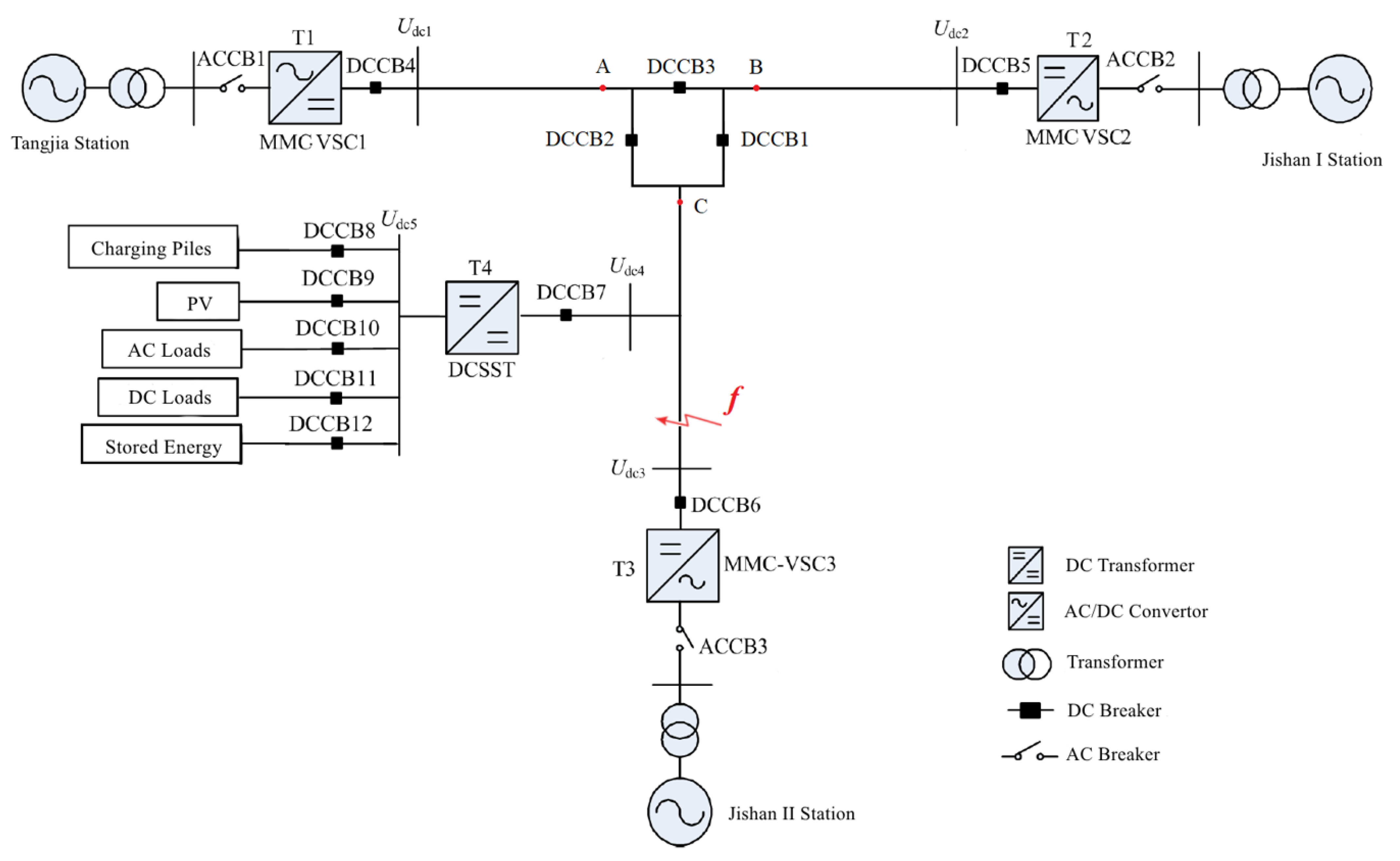
2. System Structure
2.1. MTDC Distribution Network Structure
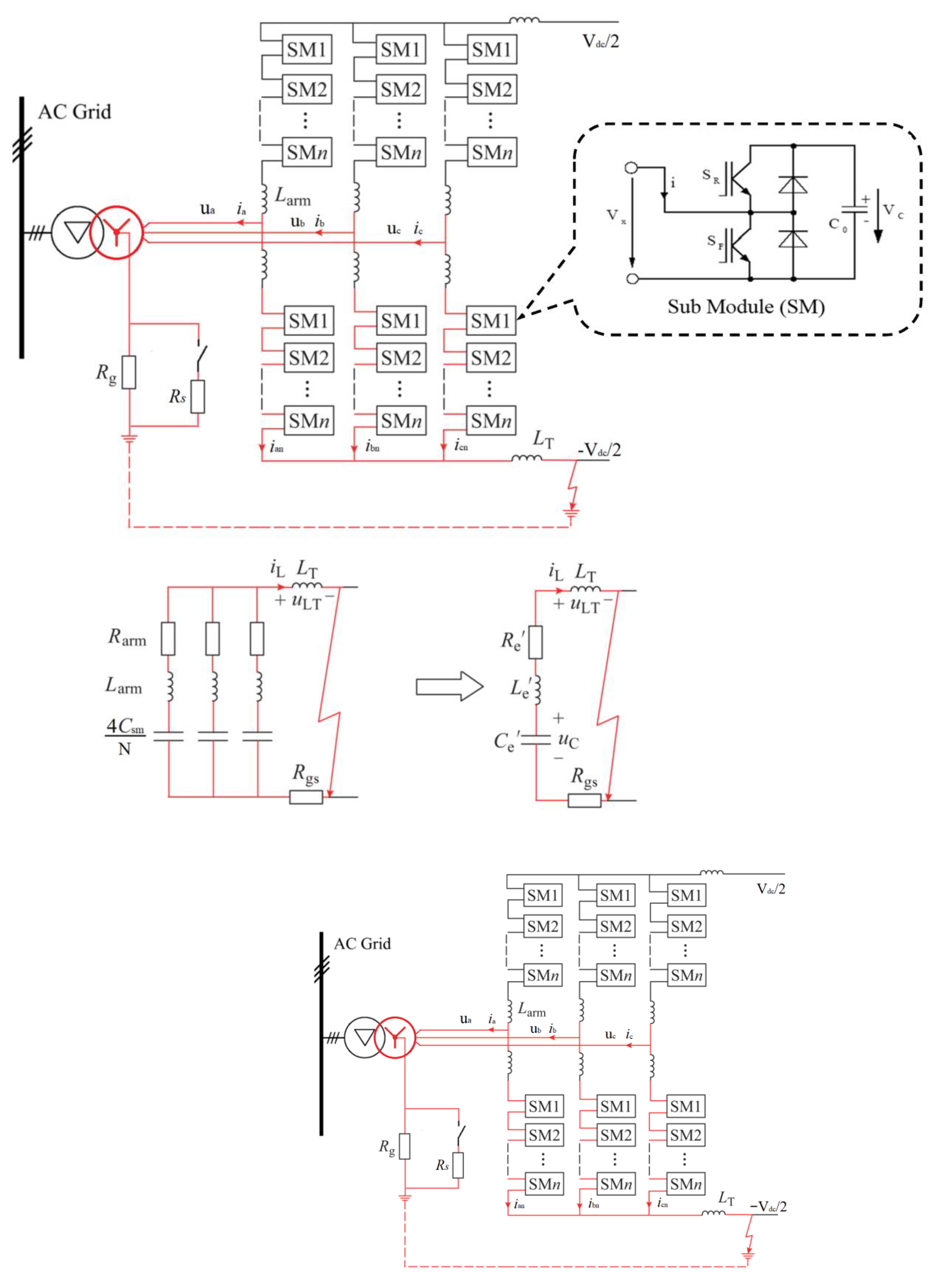
2.2. Topology of MMC
2.3. SPG Fault Model of MMC
3. Fault Criterion and Protection Scheme
3.1. Start Criterion of SPG Fault
3.2. Location Method of SPG Fault
3.2.1. Differential Protection Action Criterion
3.2.2. The Threshold Value of Current Derivative
3.3. Protection Strategy
- (1)
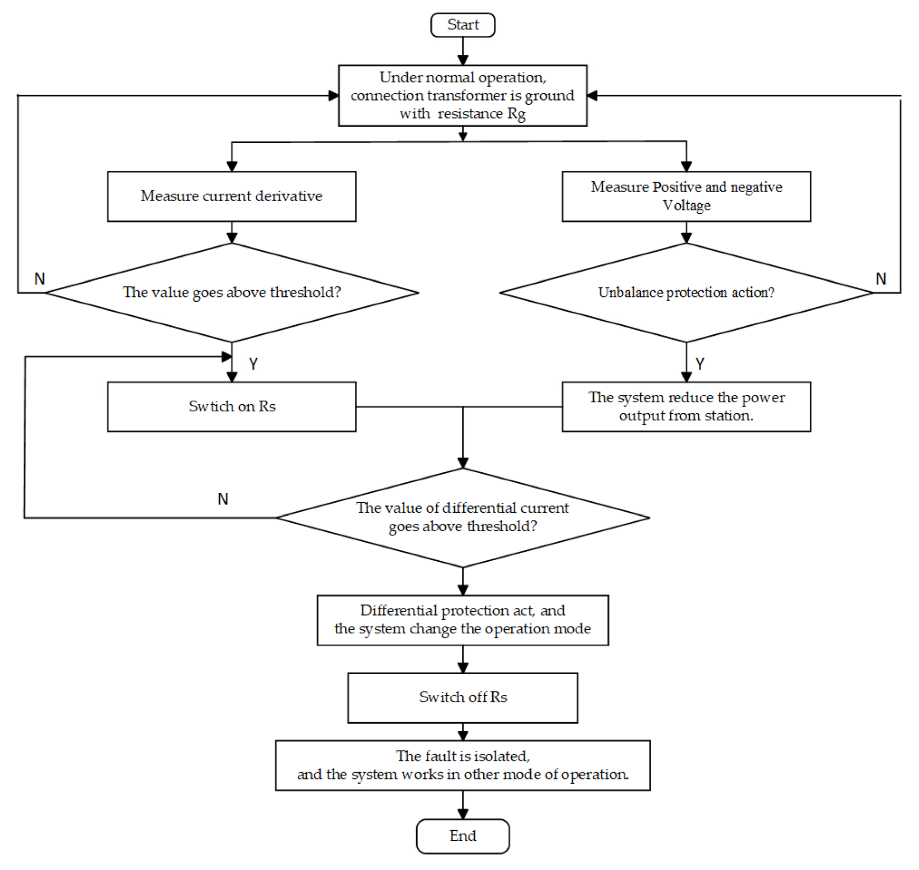
- The DC power distribution control and protection system detects the change of the DC voltage according to the Formula (4). Whether the voltage unbalance occurs will be judged in the system. Meanwhile, the current derivative is detected according the Formula (13);
- (2)
- If voltage unbalance is detected, the system reduces the power output. If the value of current derivative exceeds the threshold, the neutral point grounding small resistance Rs is switched on to increase the fault current rapidly;
- (3)
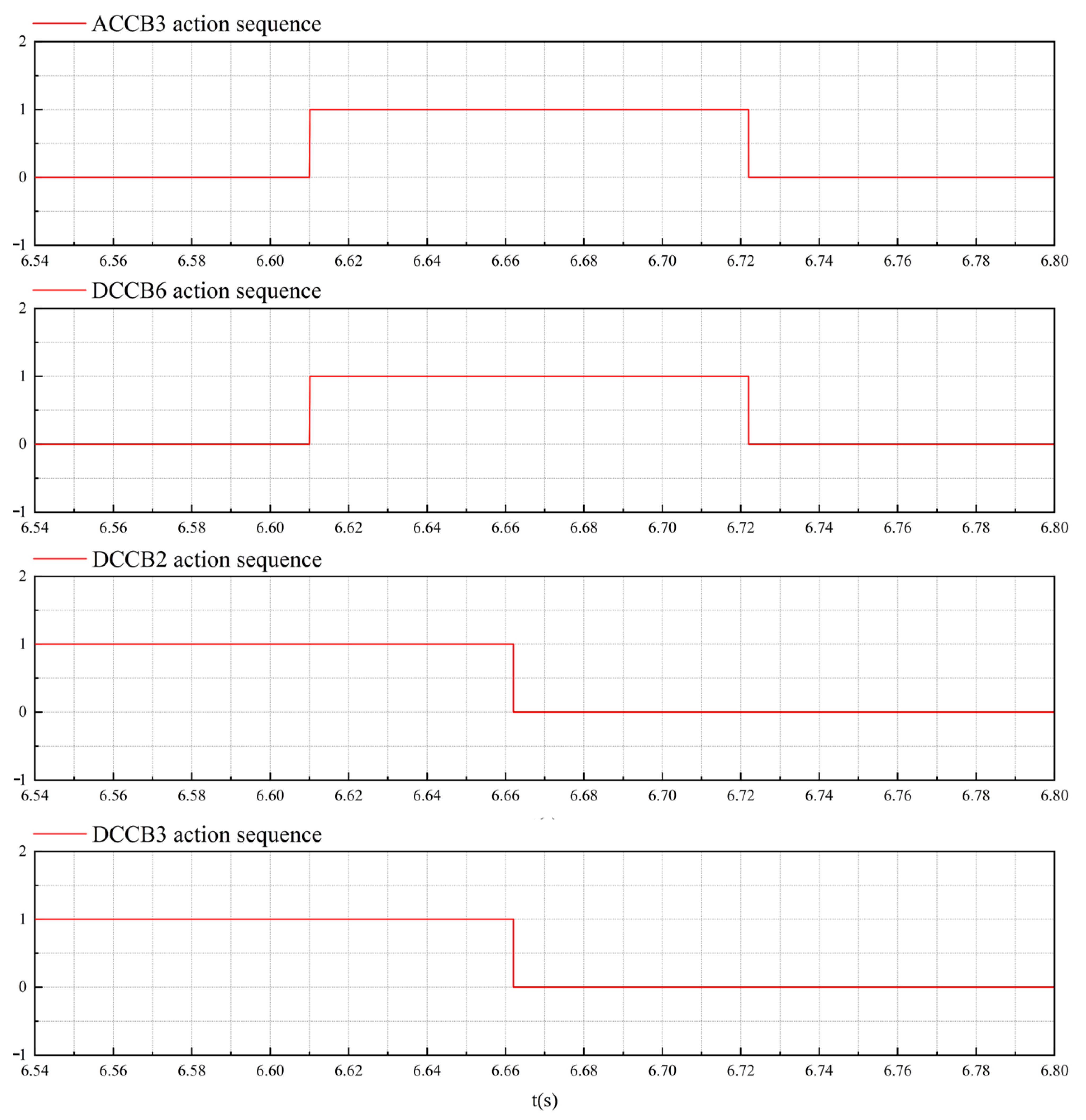
- If Formulas (10) and (14) are satisfied at the same time, it is judged that a SPG fault has occurred. After that the small resistance is switched off, and then, the fault isolation and system operation state transition procedures are entered.
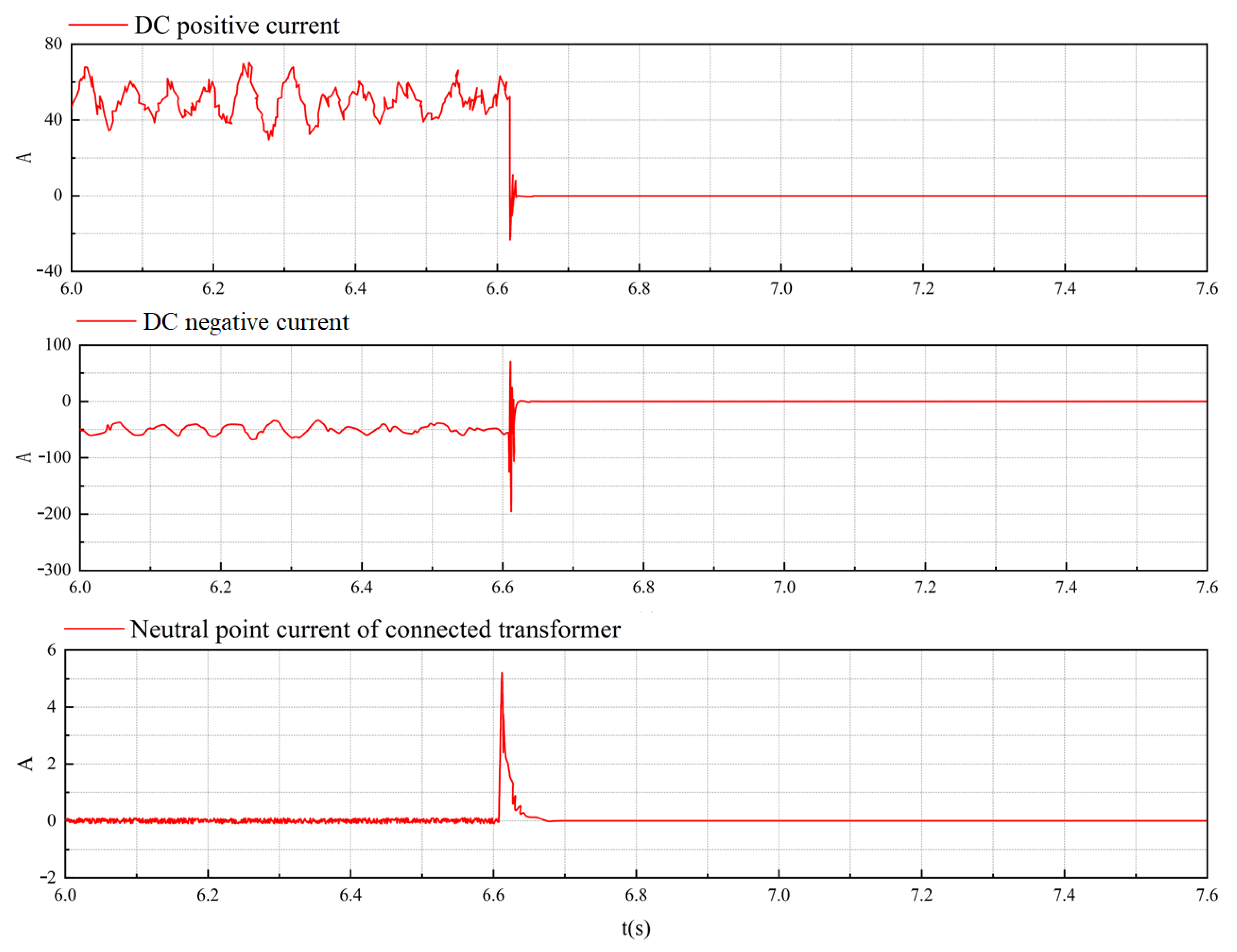
4. Experiment and Simulation
5. Conclusions
- The comprehensive use of DC reactor and neutral point grounding resistance of connection transformer is an effective means to reduce the cost of fault removal and improve the economy of the system;
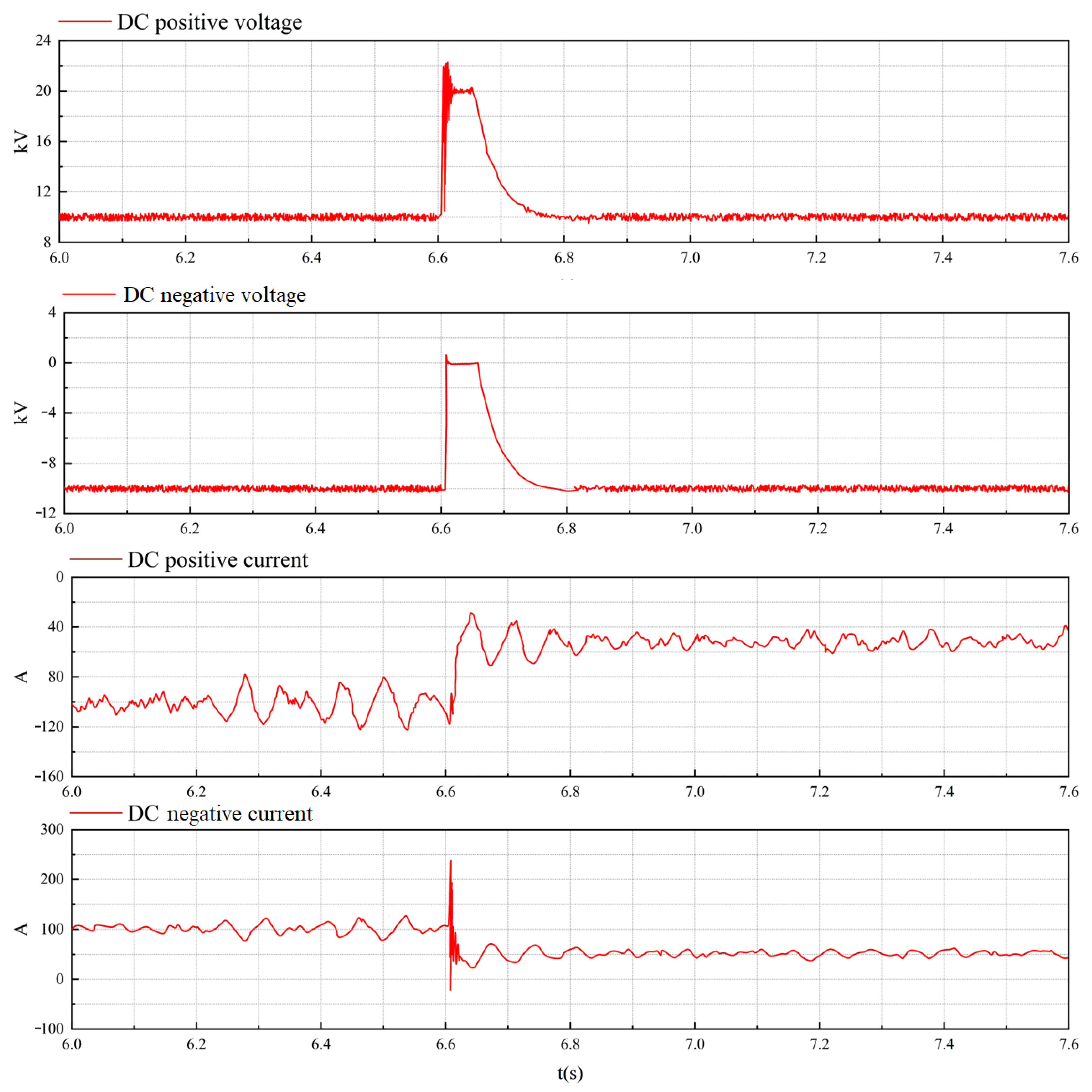
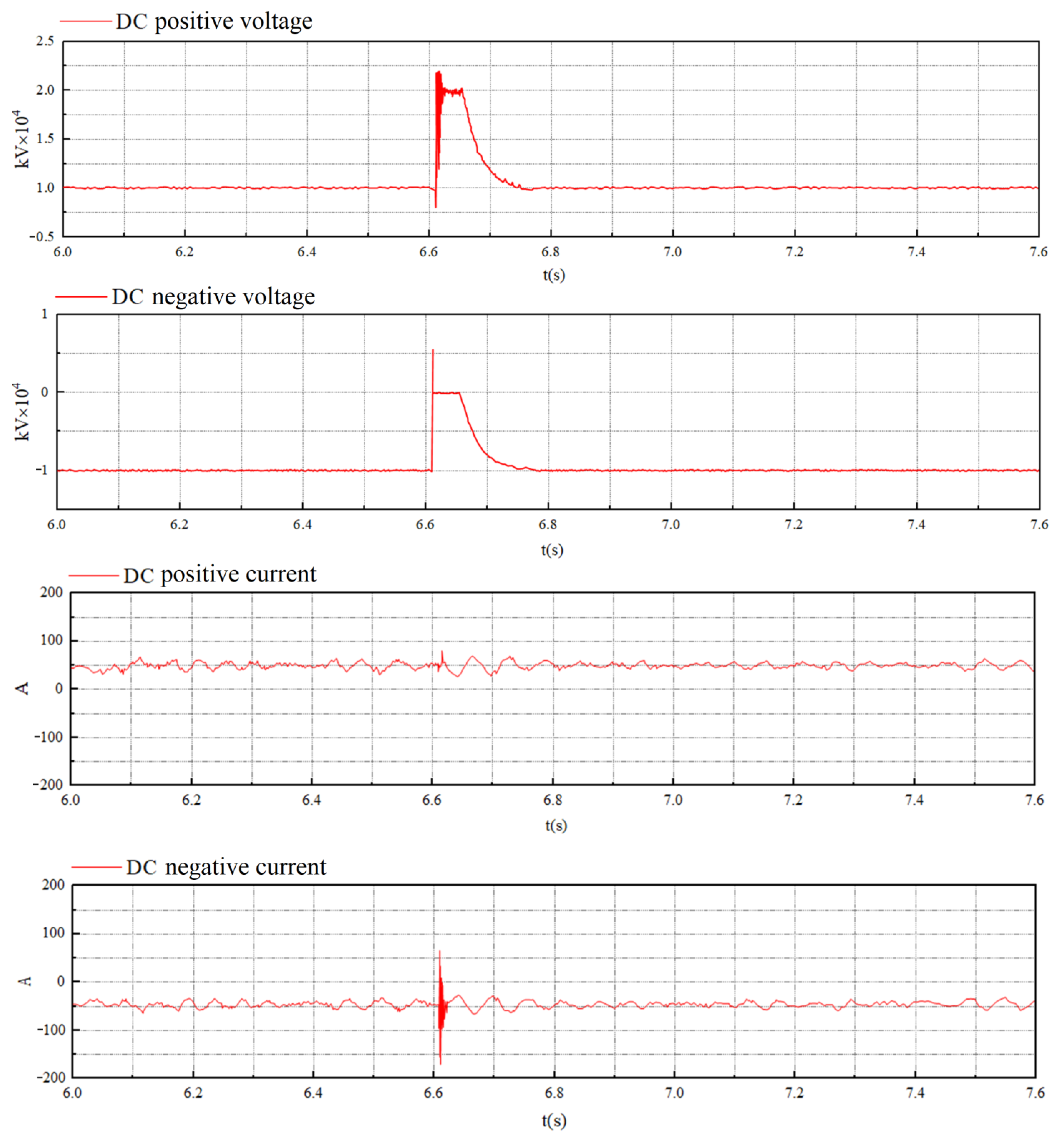
- The criterion proposed can quickly detect the DC SPG fault. Voltage unbalance protection is used as main protection. In order to locate the fault, the method of switching the small resistance by detecting current derivative is proposed. The value of fault current rises rapidly so that reliability of differential protection can be satisfied;
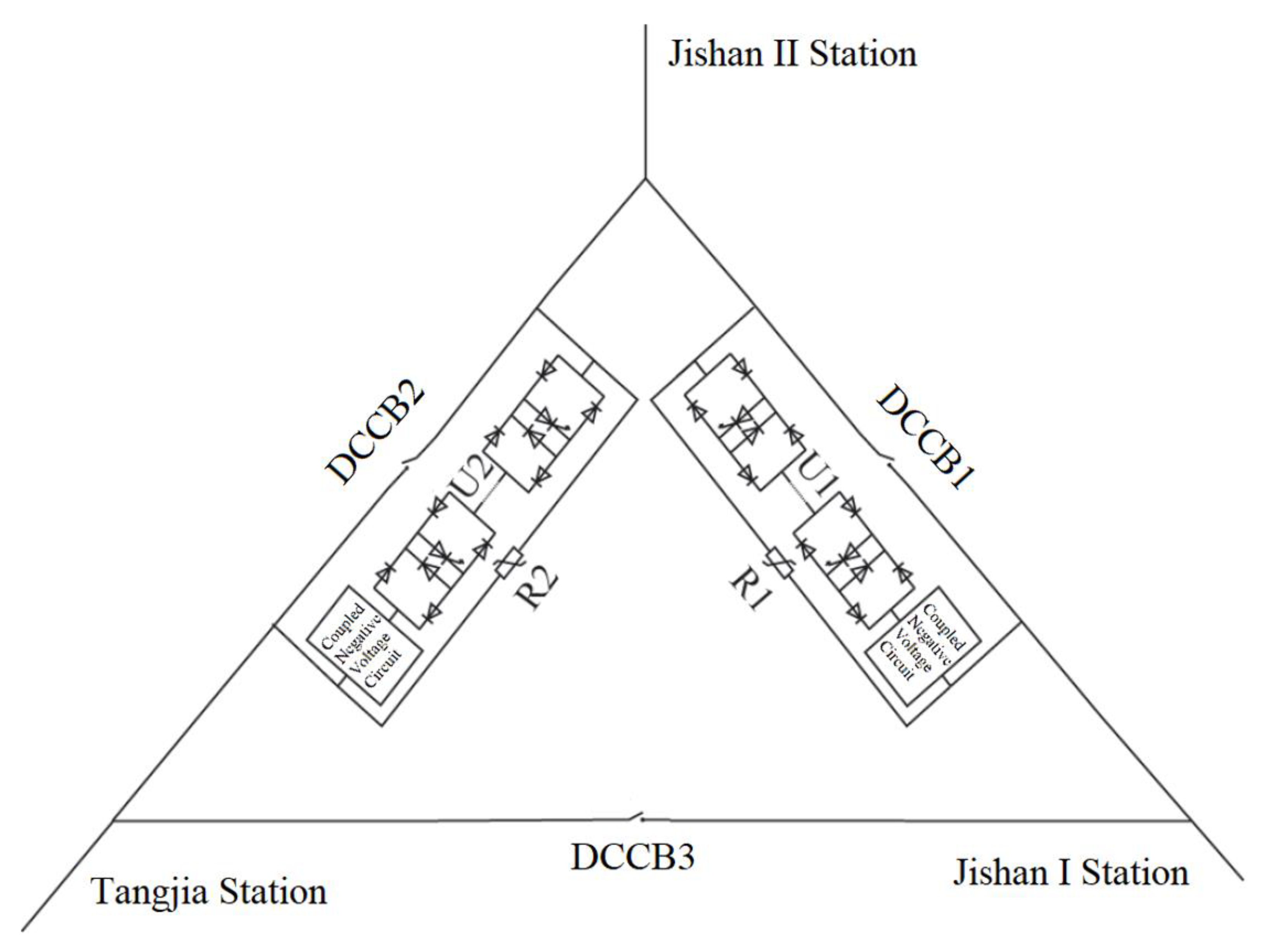
- The fault of T2 had a momentous effect on the power supply quality of other converter stations during SPG fault. The results proved that T2 can be isolated in time by three port DCCB. The operating mode of system was switched from the three-terminal network to two-terminal hand-in-hand. In future research, it will be necessary to study the influence of other faults on the MTDC distribution network. In addition, the voltage control mode of the converter station is also an important research field.
Author Contributions
Funding
Data Availability Statement
Conflicts of Interest
References
- Abedin, T.; Lipu, M.S.H.; Hannan, M.A.; Ker, P.J.; Rahman, S.A.; Yaw, C.T.; Tiong, S.K.; Muttaqi, K.M. Dynamic modeling of hvdc for power system stability assessment: A review, issues, and recommendations. Energies 2021, 14, 4829. [Google Scholar] [CrossRef]
- Stan, A.; Costinaș, S.; Ion, G. Overview and Assessment of HVDC Current Applications and Future Trends. Energies 2022, 15, 1193. [Google Scholar] [CrossRef]
- Farhadi, M.; Mohammed, O.A. Protection of multi-terminal and distributed DC systems: Design challenges and techniques. Electr. Power Syst. Res. 2017, 143, 715–727. [Google Scholar] [CrossRef]
- Tang, L.; Ooi, B.T. Locating and isolating DC faults in multi-terminal DC systems. IEEE Trans. Power Deliv. 2007, 22, 1877–1884. [Google Scholar] [CrossRef]
- Le Blond, S.; Bertho, R., Jr.; Coury, D.V.; Vieira, J.C.M. Design of protection schemes for multi-terminal HVDC systems. Renew. Sustain. Energy Rev. 2016, 56, 965–974. [Google Scholar] [CrossRef]
- Monadi, M.; Koch-Ciobotaru, C.; Luna, A.; Candela, J.I.; Rodriguez, P. A protection strategy for fault detection and location for multi-terminal MVDC distribution systems with renewable energy systems. In Proceedings of the 2014 International Conference on Renewable Energy Research and Application (ICRERA), Milwaukee, WI, USA, 19–22 October 2014; IEEE: Piscataway, NJ, USA, 2014; pp. 496–501. [Google Scholar]
- Meghwani, A.; Srivastava, S.C.; Chakrabarti, S. A new protection scheme for DC microgrid using line current derivative. In Proceedings of the 2015 IEEE Power & Energy Society General Meeting, Denver, CO, USA, 26–30 July 2015; IEEE: Piscataway, NJ, USA, 2015; pp. 1–5. [Google Scholar]
- Dai, Z.; Liu, X.; He, Y.; Huang, M. Single-terminal quantity based line protection for ring flexible DC distribution grids. IEEE Trans. Power Deliv. 2019, 35, 310–323. [Google Scholar] [CrossRef]
- Yeap, Y.M.; Geddada, N.; Satpathi, K.; Ukil, A. Time-and frequency-domain fault detection in a VSC-interfaced experimental DC test system. IEEE Trans. Ind. Inform. 2018, 14, 4353–4364. [Google Scholar] [CrossRef]
- Li, B.; He, J.; Li, Y.; Ou, Y. Single-ended protection scheme based on boundary characteristic for the multi-terminal VSC-based DC distribution system. Proc. CSEE 2016, 36, 5741–5749. [Google Scholar]
- He, J.; Li, B.; Li, Y.; Qiu, H.; Wang, C.; Dai, D. A fast directional pilot protection scheme for the MMC-based MTDC grid. Proc. CSEE 2017, 37, 6878–6887. [Google Scholar]
- Xie, Z.; Zou, G.; Du, X.; Gao, H.L. Fast DC lines protection for symmetrical bipolar based MTDC grid. In Proceedings of the CSEE 2020, Virtual, 18–20 October 2020; Volume 40, pp. 1906–1915. [Google Scholar]
- Kheirollahi, R.; Dehghanpour, E. Developing a new fault location topology for DC microgrid systems. In Proceedings of the 2016 7th Power Electronics and Drive Systems Technologies Conference (PEDSTC), Tehran, Iran, 16–18 February 2016; IEEE: Piscataway, NJ, USA, 2016; pp. 297–301. [Google Scholar]
- Liu, W.; Liu, F.; Zha, X.; Huang, M.; Chen, C.; Zhuang, Y. An improved SSCB combining fault interruption and fault location functions for DC line short-circuit fault protection. IEEE Trans. Power Deliv. 2018, 34, 858–868. [Google Scholar] [CrossRef]
- Park, J.D. Ground fault detection and location for ungrounded DC traction power systems. IEEE Trans. Veh. Technol. 2015, 64, 5667–5676. [Google Scholar] [CrossRef]
- Jia, K.; Li, M.; Bi, T.; Yang, Q. A voltage resonance-based single-ended online fault location algorithm for DC distribution networks. Sci. China Technol. Sci. 2016, 59, 721–729. [Google Scholar] [CrossRef]
- Jia, K.; Christopher, E.; Thomas, D.; Sumner, M.; Bi, T. Advanced DC zonal marine power system protection. IET Gener. Transm. Distrib. 2014, 8, 301–309. [Google Scholar] [CrossRef]
- Xue, S.M.; Liu, C.J.; Li, Z.; Lu, J.C. Ranging Protection of Ring DC Microgrid System Based on Control and Protection Cooperation. High Volt. Eng. 2019, 45, 3059–3067. [Google Scholar]
- Qu, L.; Yu, Z.; Song, Q.; Yuan, Z.; Zhao, B.; Yao, D.; Chen, J.; Liu, Y.; Zeng, R. Planning and analysis of the demonstration project of the MVDC distribution network in Zhuhai. Front. Energy 2019, 13, 120–130. [Google Scholar] [CrossRef]
- Xu, Z.; Xiao, H.; Xiao, L.; Zhang, Z. DC fault analysis and clearance solutions of MMC-HVDC systems. Energies 2018, 11, 941. [Google Scholar] [CrossRef] [Green Version]


| VSC No. | T1 | T2 | T3 |
|---|---|---|---|
| Rated Power (MW) | 20 | 10 | 10 |
| AC grid voltage (kV) | 10 | 10 | 10 |
| DC bus voltage (kV) | ±10 | ±10 | ±10 |
| Submodule topology | half bridge | half bridge | half bridge |
| Number of single-arm submodules | 25 | 25 | 25 |
| Submodule Capacitance (mF) | 30 | 15 | 15 |
| Bridge arm reactance (mH) | 3.5 | 7 | 7 |
| Transformer capacity (MVA) | 24 | 12 | 12 |
| Short circuit impedance ratio (%) | 10 | 10 | 10 |
| Winding Type | Dyn11 | Dyn11 | Dyn11 |
| DC reactor (mH) | 8 | 8 | 8 |
| VSC No. | T1 | T2 | T3 |
|---|---|---|---|
| AC system capacity | 2 MVA | 1 MVA | 1 MVA |
| AC voltage level | 10 kV | 10 kV | 10 kV |
| control mode | VdcQ | PQ | PQ |
Disclaimer/Publisher’s Note: The statements, opinions and data contained in all publications are solely those of the individual author(s) and contributor(s) and not of MDPI and/or the editor(s). MDPI and/or the editor(s) disclaim responsibility for any injury to people or property resulting from any ideas, methods, instructions or products referred to in the content. |
© 2023 by the authors. Licensee MDPI, Basel, Switzerland. This article is an open access article distributed under the terms and conditions of the Creative Commons Attribution (CC BY) license (https://creativecommons.org/licenses/by/4.0/).
Share and Cite
Yang, R.; Fang, K.; Chen, J.; Chen, Y.; Liu, M.; Meng, Q. A Novel Protection Strategy for Single Pole-to-Ground Fault in Multi-Terminal DC Distribution Network. Energies 2023, 16, 2921. https://doi.org/10.3390/en16062921
Yang R, Fang K, Chen J, Chen Y, Liu M, Meng Q. A Novel Protection Strategy for Single Pole-to-Ground Fault in Multi-Terminal DC Distribution Network. Energies. 2023; 16(6):2921. https://doi.org/10.3390/en16062921
Chicago/Turabian StyleYang, Ruixiong, Ke Fang, Jianfu Chen, Yong Chen, Min Liu, and Qingxu Meng. 2023. "A Novel Protection Strategy for Single Pole-to-Ground Fault in Multi-Terminal DC Distribution Network" Energies 16, no. 6: 2921. https://doi.org/10.3390/en16062921