Article

Energy Management System (EMS) Based on Model Predictive Control (MPC) for an Isolated DC Microgrid

by
Jonathan Andrés Basantes
1,*,
Daniela Estefanía Paredes
1,*,
Jacqueline Rosario Llanos
1,*,
Diego Edmundo Ortiz
1 and
Claudio Danilo Burgos
2
1
Department of Electrical and Electronic Engineering, Universidad de las Fuerzas Armadas (ESPE), Sangolquí 171103, Ecuador
2
Institute of Engineering Sciences, Universidad de O’Higgins, Rancagua 2820000, Chile
*
Authors to whom correspondence should be addressed.
Energies 2023, 16(6), 2912; https://doi.org/10.3390/en16062912
Submission received: 11 February 2023 / Revised: 9 March 2023 / Accepted: 13 March 2023 / Published: 22 March 2023
(This article belongs to the Section A1: Smart Grids and Microgrids)

Abstract

:
Microgrids have become an alternative for integrating distributed generation to supply energy to isolated communities, so their control and optimal management are important. This research designs and simulates the three levels of control of a DC microgrid operating in isolated mode and proposes an Energy Management System (EMS) based on Model Predictive Control (MPC), with real-time measurement feedback for optimal energy dispatch, which ensures power flow distribution and operation at minimum cost while extending the lifespan of the BESS. The EMS can react to disturbances produced in the lower control levels. The microgrid’s performance is analyzed and compared in two scenarios without EMS, and with EMS against changes in irradiation and changes in electricity demand. The fulfillment of the power balance is evaluated by analyzing the power delivered by each generation unit, the operating cost, and the state of charge of the battery (SOC).

1. Introduction

Currently, energy production is based on the consumption of fossil resources, which is an expensive process that leads to the depletion of available non-renewable resources. Therefore, the importance of the use of natural resources (renewable resources) arises at the time of introducing other forms of sustainable electricity production, supporting the environment, because this resource does not generate pollution [1,2].
The energy needs facing the world and the increase in energy consumption in the coming years make it necessary to increase the generation of electric power, which is restricted by the reduction of fossil fuel reserves and the harmful impact it has on the environment [3]. Therefore, it is important to understand the term microgrids, which are composed of energy generation sources such as solar, wind, biomass, geothermal, hydroelectric, and fossil, among others, in addition to integrating storage systems to supply local loads [4].
The classification of microgrids is very broad because they can operate in AC current, DC current, or both. Microgrids can operate in isolated mode and grid-connected mode, allowing disconnection and connection to the conventional distribution network. Isolated microgrids arise from the need to supply energy to sectors of difficult access, whether isolated or rural areas, which for the most part do not have access to electric power service [3,5,6].
Traditionally, microgrids have a three-tier hierarchical control architecture. The primary control includes the local controllers to regulate frequency and voltage and the droop control for power sharing in the dispatchable generation units. The secondary control is in charge of restoring frequency and voltage [7]. Finally, the tertiary control is in charge of the optimal management of the microgrid [8,9,10].
Therefore, microgrids have gained attention as a new alternative to face the energy transition and the challenges of energy supply, due to their versatility to operate in isolated or grid-connected mode [8]. Among the main contributions of microgrids in the energy market, it stands out that they are more efficient, reduce CO2 emissions, encourage the use of renewable energies, and reduce energy costs. In addition to the above, microgrids are not centrally planned or managed [4,5].
In the specialized technical literature, there are works such as [11], where they propose an optimal power flow approach, using iterative linear programming, in which the power flow equations are iteratively linearized around new operating points within an appropriate stability margin. When a disturbance occurs, the operating point is shifted towards the stability limit, where each iteration requires solving the nonlinear optimization problem to improve the static voltage stability; however, this work is focused on AC microgrid applications.
Currently, the distribution of DC energy through microgrids is a topic of research interest for residential applications, due to the increase in DC loads, the implementation of energy sources based on renewable resources, and the development of power electronics and storage systems [12,13].
The advantages of DC microgrids are reduction of power losses, increases system efficiency, integration of distributed generation technologies through control and monitoring, and cost reduction. They can also supply energy to a load independently when voltage fluctuations occur, ensuring an efficient, reliable, and safe system [12,14,15].
It is important to note that failure to properly manage a microgrid leads to a waste of energy resources, making it an inefficient operation. Therefore, an adequate management system is necessary to manage the energy flow of the generation units; this can be achieved with intelligent and optimal control strategies, which is how the term energy management system (EMS) appears.
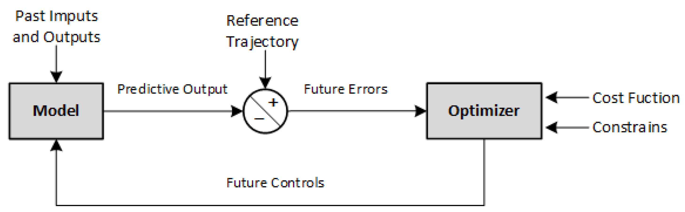
EMS is important in controlling the generation and distribution of power flow in microgrids and, therefore, minimizing operating costs [15,16]. Therefore, a control system based on MPC (Model Predictive Control) optimization is proposed, which makes explicit use of the mathematical model of the process, in addition to considering the objective function that seeks to minimize the operating cost of the system [17,18,19].
There are some EMS proposals for DC microgrids that apply various control methods. In [20], an isolated microgrid consisting of two renewable sources, a diesel generator, and a storage system is developed. The objective is to maximize the useful life of the batteries and minimize the cost of energy generation, using the multi-objective genetic algorithm NSGA-II. As a result of the optimization algorithm, several solutions are obtained that meet the cost-minimization requirements. Therefore, it is up to the researchers to select the solution that fits the physical conditions of the microgrid.
In the same context of EMS applied to DC microgrids, Ref. [21] presents a predictive control of a microgrid that can operate in island mode or grid-connected mode, using a distributed control architecture, i.e., integrating an MPC for each generation unit (wind generator and photovoltaic generator) and another MPC for the energy storage unit; therefore, this type of control makes decisions individually. In addition, management based on heuristic methods is evidenced, ensuring that the management system determines the operation mode of the microgrid based on the generated power, demand, solar irradiance, wind speed, the nominal power of the units, and the SOC of the BESS.
Meanwhile, in [22,23], the MPC control strategy is implemented to optimally manage the load sharing between generation sources, storage, and interaction with the grid if necessary. However, the management system solves the optimization problem without real-time feedback on the actual battery states.
The authors in [24,25] propose an energy management system (EMS) [24] based on a MOGA algorithm (multi-objective genetic algorithm) with a 51% reduction in operational costs and a 96% reduction in the amount of pollutant gas emissions. In [25], in addition to an EMS, they implement a demand-side management (DSM) that consists of modifying the consumption within a certain range of time, to reduce the cost and adjust the generation profiles of energy.
In [26] they use an advanced control for the management of a DC microgrid that operates in island mode through an MPC model integrating artificial intelligence (AI), where AI replaces mathematical modeling typically used when working with complex and accurate mathematical models, demonstrating that the controller is capable of providing efficient control actions for optimal energy management and a correct energy balance for the microgrid.
Ref. [27] analyzes the optimization of isolated AC microgrids that include several renewable sources and energy storage, focusing on several systems connected in the same microgrid. Therefore, for the interconnection of the microgrids, a distributed control based on the DMPC model is developed because it considers each unit as a subsystem and will be controlled by a local MPC, which is fundamental for understanding the information to be exchanged between each unit. In addition, for integrating electric vehicles (EV), it was necessary to develop an EMS to manage the use of vehicle batteries. Furthermore, Refs. [27,28] realize the integration of electric vehicles (EV), therefore the development of an EMS to manage the use of vehicle batteries is necessary.
In the previously reported works, the local controllers were not designed, nor was there online feedback on the measurements that show the current state of the batteries in the EMS system. Therefore, a control strategy is considered, with no feedback from the actual measurements, i.e., it is assumed that everything works correctly. However, disturbances at that level are not identified by the EMS.
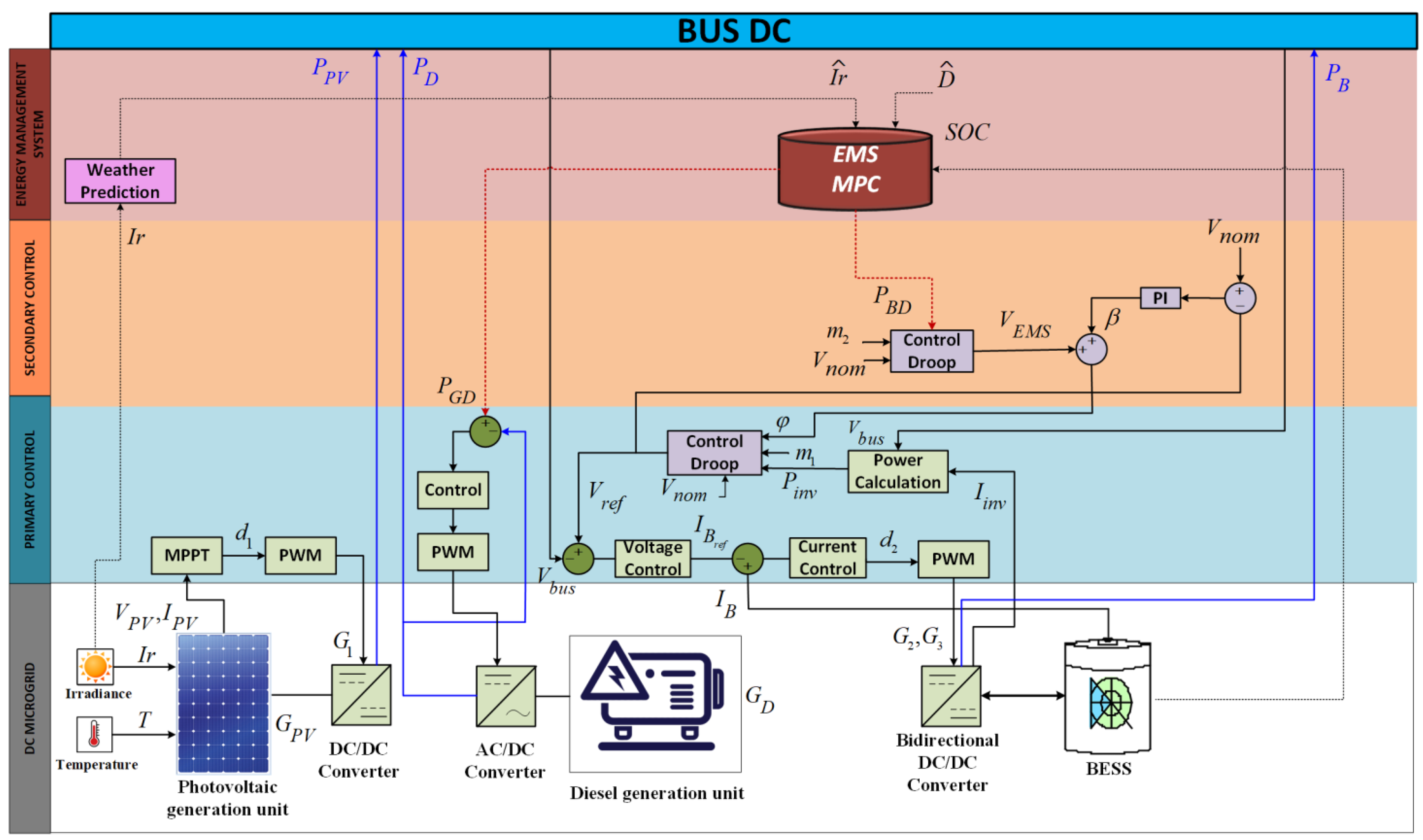
This research paper proposes the design of a tertiary EMS control for an isolated DC microgrid, consisting of a photovoltaic system that takes full advantage of the solar resource, a diesel generator as a backup power source, a battery energy storage system, and a DC load.
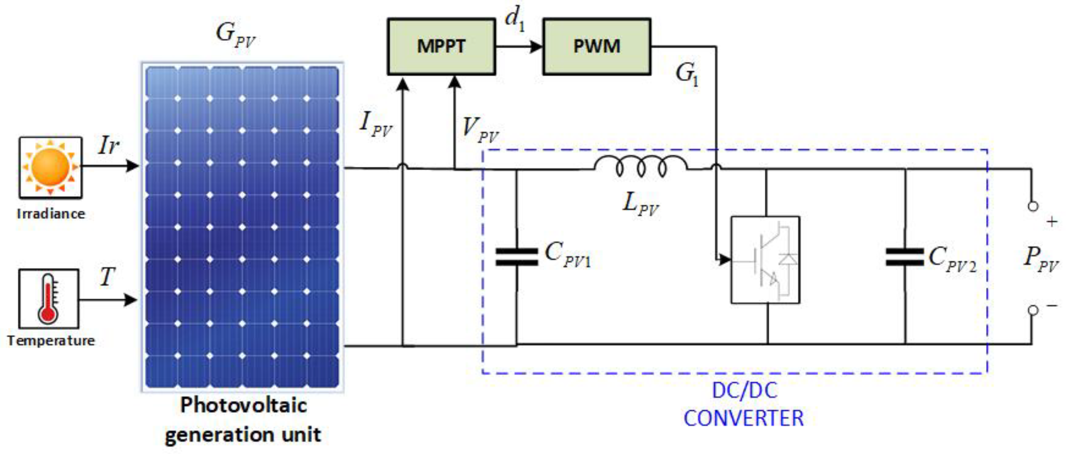
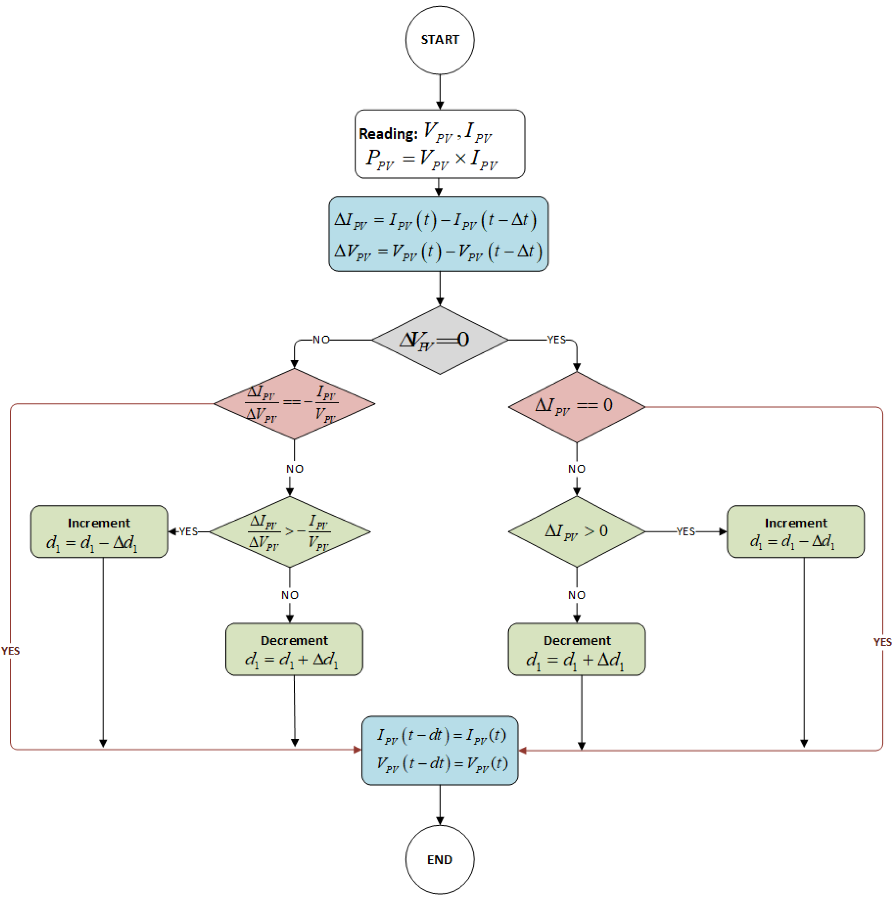
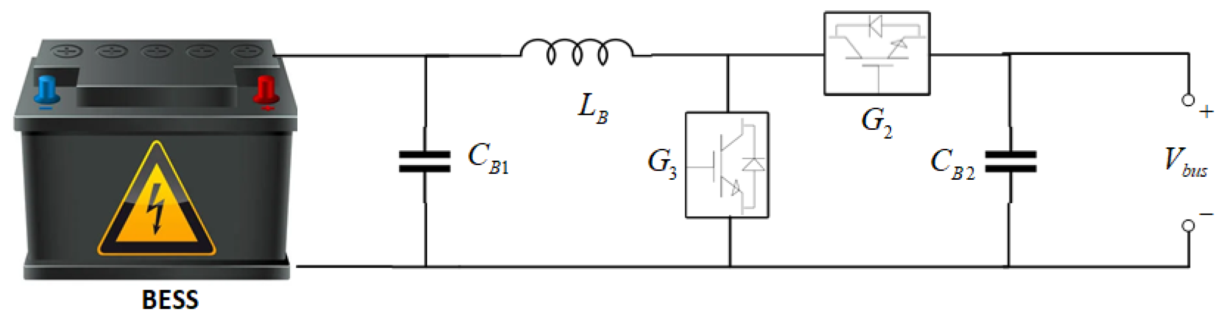
The photovoltaic system is connected to the Bus DC through a boost-type DC/DC power converter, which contains an MPPT based on the incremental conductance algorithm (INC). On the other hand, the diesel generator will operate only when necessary. The storage system, consisting of a battery bank, is connected to the Bus DC through a bidirectional buck–boost topology converter that allows operation in charge and discharge mode of the storage system.
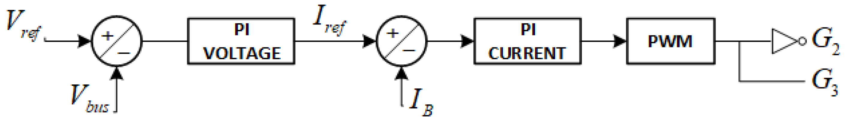
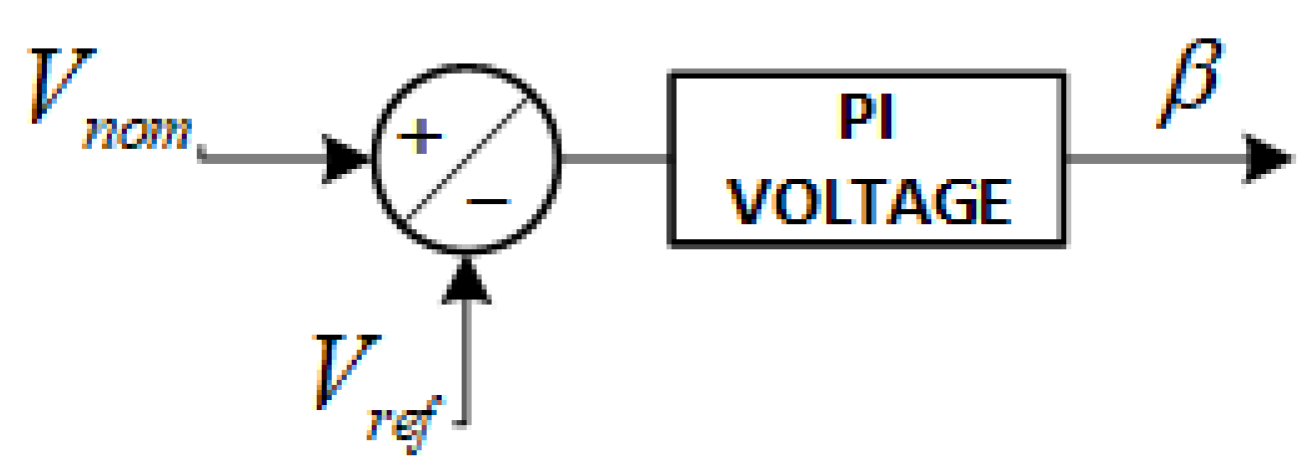
The control of the microgrid is performed by a local PI voltage and current controller, which allows maintaining a constant voltage on the Bus DC and the droop control to share the power generated by each generation unit. The optimal management is performed by an EMS, which allows optimal and efficient decision making in the management of the system, controlling several generation units including a photovoltaic system, BESS storage system, and a diesel generator, which will be able to feed a DC load.
All control levels are designed, but mainly in this work, an EMS based on MPC is proposed to maximize the consumption of energy based on renewable resources (sun) and minimizing the consumption of energy from the diesel generator and costs for the energy consumption. It also has the scope of increasing the useful life of the battery while respecting the SOC, guaranteeing optimal charging and discharging.
The main contributions of this research work are: (i) Proposing a control strategy for the optimal management of an isolated DC microgrid, maximizing the use of solar resources, extending battery life, and minimizing the operating cost of the microgrid, through the optimal distribution of power, based on linear programming guaranteeing the global optimum; (ii) Design and simulate all levels of control, integrating primary, secondary, and tertiary control, making measurements in real-time, which allows understanding the operation of the microgrid in a couple, where the tertiary control (EMS) responds to changes in the lower control levels when disturbances occur; therefore the operation of the DC microgrid is integral; (iii) The tertiary control is based on MPC operating in sliding mode; in this way the EMS designed allows reaction to rapid changes in demand and irradiation, being able to detect changes in input variables.
The rest of this document is organized as follows: The system description (Section 2) shows each of the elements that make up the microgrid and how it will be controlled by the EMS. The design of the control and management algorithms of a DC microgrid is presented (Section 3), where the architecture of each control level is explained in detail. The results (Section 4) show the comparison of the operation between a microgrid with and without the proposed EMS. The conclusions (Section 5) show a quantitative analysis of the costs generated by not having a tertiary control that adequately manages the power supplied by each generation unit, and the optimal operation of the DC microgrid with all levels of control.

2. System Description

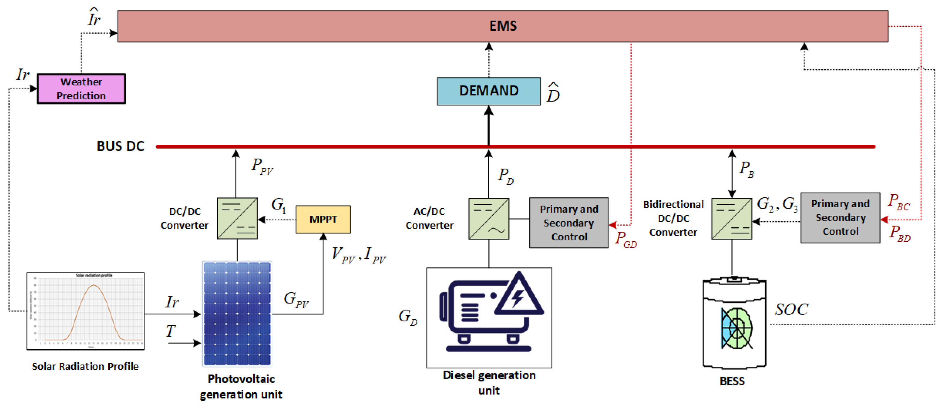
As mentioned above, this research proposes the control of an isolated DC microgrid, as shown in Figure 1, consisting of a photovoltaic generation unit ( G P V ), a diesel generation unit ( G D ), and a battery energy storage system (BESS), connected to a bus DC that supplies power to a DC-type load at a constant power.
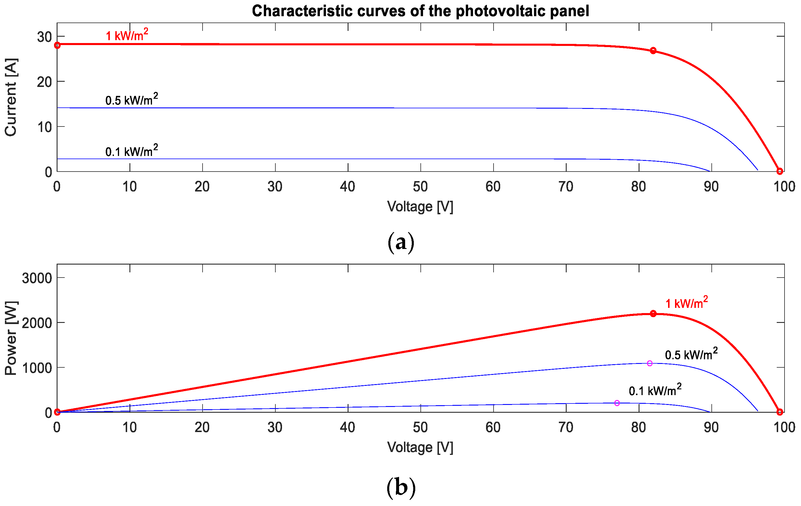
The photovoltaic generation unit capture la solar irradiation (Ir), transforming it into electricity, an energy that is injected into the Bus DC to supply demand; it is also important to note that I r is an input to a prediction model, and its output ( I r ^ ) will be the input to the EMS optimization problem. The photovoltaic panels have a voltage response ( V P V ) and current ( I P V ) depending mainly on the solar irradiance ( I r ) and temperature ( T ), which are external factors that directly affect its operation [29]. This unit provides photovoltaic power represented by ( P P V ), which is controlled by an incremental conductance MPPT that generates the G 1 trigger to activate the IGBT of the DC/DC converter.
On the other hand, the diesel generator is in charge of transforming the fuel into electrical energy, represented as diesel power ( P D ) . Its main objective in microgrids is to be an auxiliary unit as a support in case the predicted electrical demand ( D ^ ) is not covered by other generation units. Its operation depends on the diesel generator power calculated by the EMS ( P G D ) . This diesel generation unit, being an alternating current source, needs an AC/DC converter to be implemented in a DC microgrid, thus performing the conversion to be able to feed the direct current load.
The battery energy storage system (BESS) will be able to deliver energy on demand, expressed as the battery power ( P B ) , which can operate in charge mode when ( P B ) has a negative sign and discharge mode when it has a positive sign. However, in the process of charging and discharging the battery, overloads and deep discharges cannot be allowed indefinitely, because this seriously compromises their useful life. Therefore, the SOC (State of Charge) is important for the analysis between the amount of power that can be obtained from the battery with respect to the total power. In order to keep the batteries within the safe operating threshold, control strategies are implemented to prolong their useful life.
These modes of operation are performed by the bidirectional DC/DC converter regulated by the EMS control signal, battery discharge power calculated by the EMS ( P B D ), and battery charge power calculated by the EMS P B C , allowing it to generate the triggers in G 2   and   G 3 for the activation of the IGBT circuit breakers on the values of P B C and P B D provided by the EMS.
Therefore, the different levels of control are designed and analyzed; the first level corresponds to the local control that constitutes the voltage and current controllers, the droop control, the voltage regulators, and finally an EMS management system. It is important to consider that the EMS is based on an MPC controller, capable of making optimal and efficient decisions in the management of the DC microgrid, based on the real-time status of variables such as the state of the battery.

3. DC Design of Control and Management Algorithms of a DC Microgrid

This section shows the control levels implemented in the DC microgrid (Figure 2). The lowest level of the control architecture is Primary control (light blue section), where the primary controllers in charge of keeping the generation levels regulated and distributing the power based on the capacity of the generation units are located. The Secondary control (orange section) represents the control in charge of restoring the voltage to its nominal value. Finally, the third level Energy management system (brown color) is in charge of the optimal management of the DC microgrid, to satisfy the demand and maintain the balance of the system operating at minimum cost.
As can be seen, the photovoltaic generation unit control requires a primary control, while the battery control contains a primary control and a secondary control, which allows operation in both charge and discharge mode of the BESS. The diesel generator as well as the battery when operating in discharge mode are dispatchable units; therefore, they have the characteristic of receiving the order from the EMS of the power to be delivered. Each level of control mentioned above is detailed in the following sections.

3.1. MPPT Control Strategy for the Photovoltaic System

The sun is a renewable and inexhaustible resource that produces energy, which can be collected and converted into heat (thermal energy) or electricity (photovoltaic energy) to meet the electricity demand [30].
Photovoltaic panels do not fully supply conventional loads, due to low voltage levels and low efficiency. Therefore, efficient control systems are needed to maximize the use of renewable resources. The objective is to develop and implement a control strategy to achieve maximum power point tracking (MPPT) of the photovoltaic array, using a DC/DC Boost converter [31,32,33].
For the MPPT control, it is necessary to feed back on the voltage ( V P V ) and current ( I P V ) of the photovoltaic panel to calculate the maximum power point; finally, the PWM will generate the triggers to the gate pulse ( G 1 ) of the IGBTs to proceed to its activation, allowing it to obtain the voltage to be connected to the Bus DC of the microgrid; see Figure 3.
The important parameters used for an MPPT are irradiance and temperature because they directly affect the amount of electricity a photovoltaic panel can produce. In Figure 4, the maximum power operating point is shown by the characteristic curve of the photovoltaic panel. Figure 4a shows the relationship between current and voltage, while Figure 4b shows the relationship between power and voltage [31].
Several algorithms allow obtaining the MPPT; in this case, the incremental conductance algorithm was selected, for easy implementation and lower computational cost. This control technique is the most widely used because it can quickly calculate the maximum power point in the face of disturbances due to rapidly fluctuating weather conditions [34].
According to [31,35], the incremental conductance algorithm (INC) is based on the slope of the power curve being zero in Equations (1) and (2) [36]. To begin with, the algorithm measures the voltage and current changes of the solar panels at the current time, and then compares them with the previous cycle measurements to predict the effect of a voltage change; to achieve the MPP it must be fulfilled that the rate of change in the output conductance, d I P V d V P V , is equal to the negative of the instantaneous conductance, I P V V P V , as in Equations (3) and (4). This algorithm can follow irradiance changes faster than the perturbation and observation (P&O) algorithm; for this reason it requires more complexity in its calculations, also according to [36] when the null derivative condition rules out steady-state oscillations.
d P P V d V P V = 0
Given that P P V = V P V × I P V
d ( V P V × I P V ) d V P V = 0
I P V + V P V d I P V d V P V = 0  
d I P V d V P V = I P V V P V
where d P P V is the derivative of the power photovoltaic panel, d V P V is the derivative of the photovoltaic panel voltage, d I P V is the derivative of the photovoltaic panel current, I P V is the photovoltaic panel current, and V P V is the photovoltaic panel voltage. When this is not satisfied, the points around the maximum point expressed in Equations (5) and (6) are analyzed [35].
S i   d I P V d V P V > I P V V P V ,   t h e n   d P P V d V P V > 0         l e f t
S i   d I P V d V P V < I P V V P V ,   t h e n   d P P V d V P V < 0         r i g h t
Next, Figure 5 shows the implemented incremental inductance scheme, and its output will be the control signal for the PWM control that will go to the IGBT G 1 .

3.2. Local Control Strategy for the Storage System

The local control of the battery is responsible for keeping the generation levels regulated and avoiding deviations from the basic parameters in the power converters. This level of control is the fastest because it acts locally on the controls of the generation units; its purpose is to maintain the voltage and current within the limits [37]. For local control of the storage system, a bidirectional DC/DC converter is implemented, which is used for energy storage applications where the ability to transfer energy in two directions is required [38]. Because they seek to connect the battery for charge and discharge operation, they must be connected via a converter that allows both energy transfers [39].
Thos is why, in this research, a “buck–boost” converter has been used, which is shown in Figure 6, working as Buck in BESS charging mode and Boost in discharging mode, depending on the control signal coming from the PWM regulated by the local voltage and current controllers, see Figure 7, which generates the gate pulses, G 2 and G 3 , for the activation of the IGBT power switches [40,41,42].
The local controllers consist of: the proportional-integral (PI) voltage controller, which maintains the voltage balance on the Bus DC, and the PI current controller, which is responsible for increasing or decreasing the amount of current depending on the demand, as well as the transition of the operating modes of the storage system, and the PWM signal modulator will activate the IGBT switching elements, with the negated signal of the G 2 and the signal of the G 3 ; see Figure 7 [34,41].
The cascade control of voltage and current is shown in Figure 7. The voltage controller regulates the battery voltage by maintaining the Bus DC voltage at a constant value, and the current control determines the mode of operation in both charge and discharge modes. V r e f is the droop control output reference voltage, V b u s is the measured Bus DC voltage, I r e f is the reference current of the voltage PI controller output, I B is the battery current measurement, and G 2 and G 3 represent the IGBT triggers to the DC/DC converter. C B 1   and C B 2 are the storage system DC/DC converter capacitors, L B is the converter inductor, and PI is proportional integral control.
To share power between different generation units, droop control is required, which is part of the primary control.

3.3. Droop Control Voltage—Power

Voltage droop control is a conventional method used for its ability to connect multiple generating units and distribute the power. Droop control is expressed in (7).
V r e f = V n o m m 1 × P i n v
m 1 = Δ V m a x P m a x
Δ V m a x = V n o m V m i n
where V r e f is the droop control output, V n o m is the nominal DC microgrid voltage, m 1 is the droop control coefficient, and P i n v is the inverter filter output power.
In (8), the relationship between the maximum acceptable voltage variation, Δ V m a x and P B m a x , is maximum power of the BESS. The Δ V m a x is obtained in (9), and the V m i n is 5% of the nominal voltage, V n o m .

3.4. Secondary Control Strategy for the Storage System

The voltage restorer corrects the deviations caused by the primary control using a PI controller, see Figure 8, to maintain a constant voltage on the Bus DC, where V n o m is the desired voltage on the Bus DC, V r e f is the output of the droop control, and β is the control action [7,43].
Equation (7) is modified by the secondary control action, β , to restore voltage, and Equation (10) is obtained; β corresponds to the secondary control action that allows voltage restoration; see Figure 8.
V r e f = V n o m m 1 × P i n v + β        
Finally, the tertiary control or EMS sends the power to charge and discharge the batter; this power, to be included in the lower levels of control, is transformed into voltage, for which the droop Equation (11) is used, the same as that input as the reference power of the droop P B D . In this way, the output, V E M S , is incorporated into (10), and Equation (12) is obtained, where V E M S corresponds to the voltage delivered by the EMS control level for the optimum management of the microgrid.
V E M S = V n o m m 2 × P B D
V r e f = V n o m m 1 × P i n v + β + V E M S
The description of the predictive controller used for optimal microgrid management is described in the following section.

3.5. Optimal Energy Management

An energy management system (EMS) is in charge of managing the operation of the microgrid and energy demands, allowing it to satisfy the energy balance in a system [44].
For this research, an MPC strategy is proposed, which allows the optimal control of energy flow in a microgrid. This is based on the optimization of an objective function. Using a mathematical model, the prediction model predicts the future state of the system and calculates the optimal control solution, providing online control without the need for the implementation of a preset control law as in traditional control systems [44].
According to [17,44], the advantages offered by MPC control are:
  • It can compensate for dead time;
  • It compensates for measurable disturbances;
  • The control law is easy to implement;
  • It works the constraints in a systematic and conceptually simple way.
The optimizer provides the optimal inputs of the MPC by minimizing the objective function, also known as the cost function. The outputs are predicted by the mathematical model that takes the past signals (input and output signals) and the future signals, as shown in Figure 9 [44].
The generation units require modeling to predict their status, which is described below.

3.5.1. Objective Function

The objective function implemented in the EMS system is defined by (13) to solve the optimal dispatch of the microgrid. The objective function minimizes the operating cost of the microgrid because the generation of energy based on fossil fuel is the only resource that has a cost; therefore, it is necessary to minimize its consumption. In addition, it minimizes the unsupplied power and thus guarantees the supply of the demand, where t represents the samples and i the prediction horizon.
m i n P G D ,   P N S ,   P B C ,   P B D ,   X G D , X B C ,   X B D t = 1 i [ P G D ( t ) × c o s t G D + P N S ( t ) × c o s t N S ]
where P G D   is diesel generation power calculated by the EMS, P N S represents the power not supplied, and c o s t G D is cost of diesel power generation, and the cost of unsupplied power is defined by c o s t N S .
As the system evolves, t is increased sequentially, so the EMS input data are periodically updated and therefore the optimization problem is updated with the new information obtained, and the solutions are calculated, allowing the control system to be able to compensate for any perturbation.
The optimization variables are expressed as P G D ,     P N S ,     P B C ,     P B D ,     X G D ,       X B C   y   X B D , where P B C is battery charging power calculated by the EMS, P B D is battery discharge power calculated by the EMS, and X G D represents the activation status of the diesel generator, while X B C   is the binary variable of the activation status of the battery charge mode and X B D is the binary variable of the battery discharge mode activation state.
It is important to mention that the energy dispatch priority is focused first on renewable energies that do not present operating costs, then on the BESS, and finally on the diesel generation unit in the case of not being able to meet the demand. It is therefore important to maintain the balance between voltage, power, and energy (produced, consumed, and stored). The optimization problem is subject to the constraints of the microgrid, as described below.

3.5.2. Constraints and Models of System

To solve the optimization problem, the following equation and inequality constraints are considered for the process, as described below.

Balance Condition

The microgrid needs to satisfy the balance equation; therefore, the power supplied by the generation units must be equal to the demand, which is analytically represented by Equation (14).
Where the generation units are diesel generation power calculated by the EMS ( P G D ), photovoltaic power ( P P V ) , battery discharge power calculated by the EMS ( P B D ) , unsupplied power ( P N S ) , battery charge power calculated by the EMS ( P B C ) , and the electrical demand as D .
D ( t ) P N S ( t ) P B C ( t ) = P G D ( t ) + P P V ( t ) + P B D ( t )

Diesel Generator Constraints

The power of the diesel generator must be kept within the generation limits according to its technical characteristics, which is represented by the inequality constraints defined in Equation (15), where the binary variable, X G D , is the binary variable of the activation status of the diesel unit. Equation (15) corresponds to the power limits that the diesel generator unit can deliver, where P G D m a x is the maximum diesel power and P G D m i n is the minimum diesel power.
P G D m i n × X G D ( t ) P G D ( t ) P G D m a x × X G D ( t )

BESS Constraints

The modeling of the BESS is shown by Equations (16) and (17), where Equation (16) represents the initial condition and Equation (17) is used to represent the energy of the BESS for any instant of time.
E ( t ) = E 0 + n B C × P B C ( t ) P B D ( t ) n B D
E ( t ) = E ( t 1 ) + n B C × P B C ( t ) P B D ( t ) n B D
where E ( t ) is instantaneous of the BESS power, E 0   is the initial energy of the BESS, n B C is the BESS performance in charging mode, and n B D is the BESS performance in discharging mode, while E ( t 1 ) represents BESS energy at the previous instant.
Equation (18) defines the boundary constraint of the BESS based on the SOC, to keep the BESS within the safe operating threshold, prolonging the lifespan, where S O C m a x represents upper charge limit of the BESS and S O C m i n is the lower discharge limit of the BESS.
S O C m i n S O C ( t ) S O C m a x
To ensure that the charging and discharging of the BESS do not occur simultaneously, constraint (19) is added.
The power limits of the storage system are also capacity constraints, which are described in Equations (20) and (22) for charging and discharging, respectively, where P B m a x represents the maximum power of the BESS.
X B C ( t ) + X B D ( t ) 1  
0 P B C ( t ) ( P B m a x ) × X B C ( t )
0 P B D ( t ) ( P B m a x ) × X B C   ( t )  
E ( t ) P B m a x

Modeling of Solar Panels

The model designed in the MPC controller for the photovoltaic panels is defined by Equation (23).
P P V ( t ) = n P V × n i n s t × A t × I r ( t )
where n P V is the photovoltaic panel performance, n i n s t is the photovoltaic panel installation performance, A t is the total area of the panel array, and I r is the irradiance.
It is important to mention that the irradiance vector with dimension i is input to the EMS optimization problem, as shown in Figure 2, and corresponds to the output of a prediction model. For the developed research, it is taken into consideration that the solar resource is a time series, which is generated by a predictor model reported in [45].

4. Result

For this research, we propose an energy management system based on an MPC control for a DC microgrid in island mode with real-time measurement feedback, for which the controls at the lower levels are implemented. The performance of the microarray without and with EMS is compared.
The microgrid consists of a photovoltaic generation unit, BESS, and a diesel generation unit connected to a Bus DC with the corresponding power electronics interfaces to supply a DC load, as shown in Figure 1. The models of the generation units and controllers designed at the different control levels described in Section 3 ere simulated in Matlab/Simulink R2016a software. For the design and simulation of the proposed optimization problem, the Fico Xpress Optimization software was used, linking the two softwares to emulate a real operation where the supervisory control for the microgrid management sends and receives signals from the microgrid operation. The simulation parameters used for the microgrid are described in Table 1, Table 2, Table 3 and Table 4. The photovoltaic generation unit operating parameters, BESS parameters, and diesel generator unit parameters are shown in Table 1, Table 2 and Table 3, respectively, while the converter and load parameters are shown in Table 4.

Evaluation of DC Microgrid Operation

This section validates the performance of the DC microgrid. The following scenarios are analyzed and compared: (i) without considering the optimal management of the EMS, only with the primary controls; (ii) considering the optimal management of the proposed EMS, which includes real-time feedback of the measured variables, and the EMS is operating in sliding mode, i.e., it takes samples every 5 s and recalculates the optimal solutions for the control of the microgrid. The microgrid is subject to disturbances from changes in radiation and changes in demand. The microgrid’s performance is analyzed in terms of technical, economic, and optimal battery management.
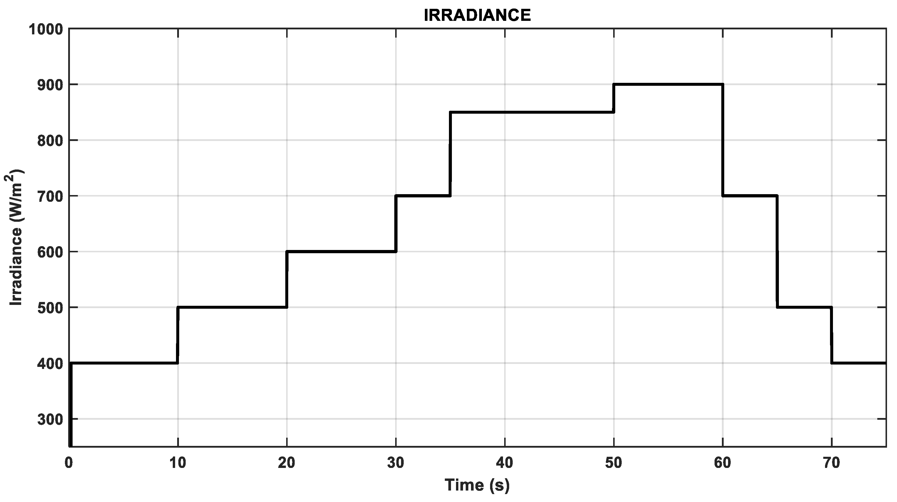
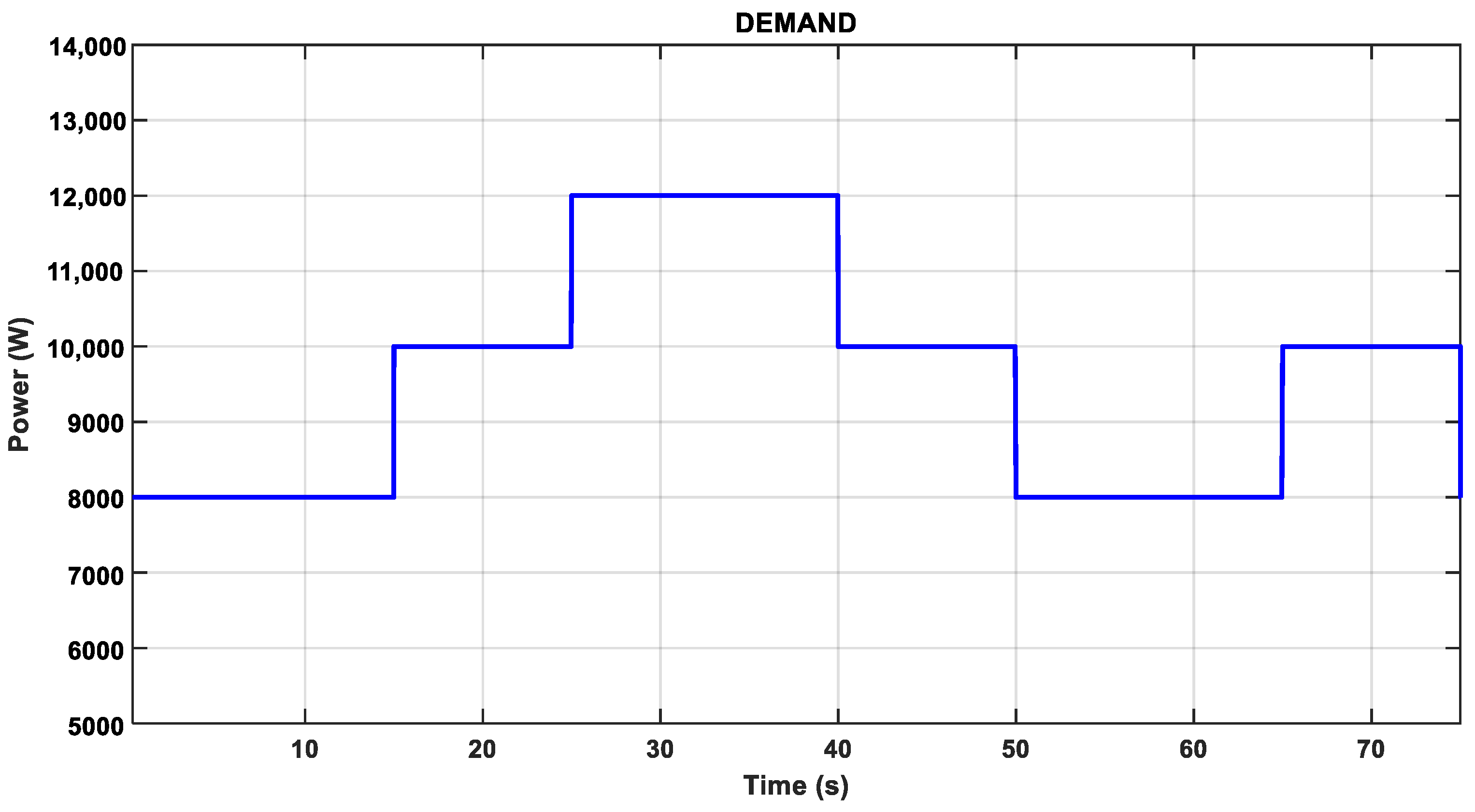
The results obtained by applying the radiation profile (Figure 10) and demand changes (Figure 11) are shown in Figure 12 and Figure 13 for the scenarios with and without EMS. The radiation profile ranges from 400 W/m2 to a maximum irradiance of 900 W/m2 at different time intervals.
Given the radiation profile proposed in Figure 10 and the demand profile as shown in Figure 11.
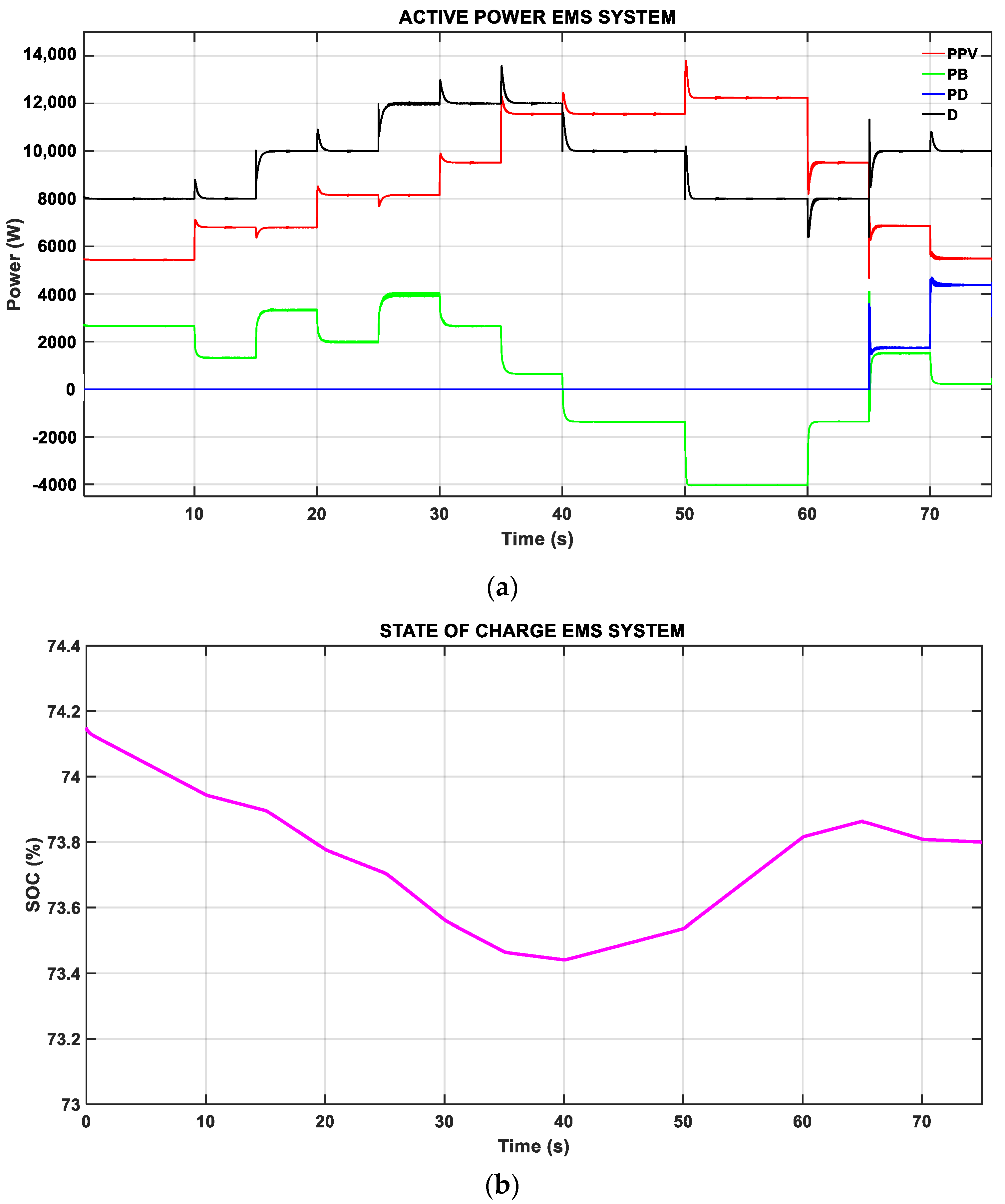
Figure 12 shows the performance of the DC microgrid. Figure 12a shows the active power distribution when operating with the proposed EMS; this information is also visible in Table 5. During the time interval from 0 to 10 s, to supply the demand, the photovoltaic panels deliver their maximum power (red line), which is not enough to meet the power balance, so the EMS resolves that the optimal dispatch is that the battery enters the remaining power (green line) to meet the demand (black line). In addition, after 5 s the controller is run again with the updated inputs and measurements, and it can be noted that there is no change in the power distribution. At 10 s, there is an increase in radiation, and it is shown how the battery reduces the power generated to take advantage of the natural resource. At 15 s, there is an increase in demand of 10,000 W, and because the solar power remains equal to the previous operating point of the battery support to meet the power balance, in the interval from 20 to 40 s there is a variation of demand and solar power; however, the demand is always higher, which leads to the battery delivering the necessary missing power to meet the balance of power. In the time intervals from 40 to 65 s, it can be noticed that the photovoltaic power is higher than the power required by the demand, and with the objective of not wasting the natural resource, the battery starts to charge; therefore, they present a negative power, i.e., the battery becomes a load of the microgrid. However, as shown in 
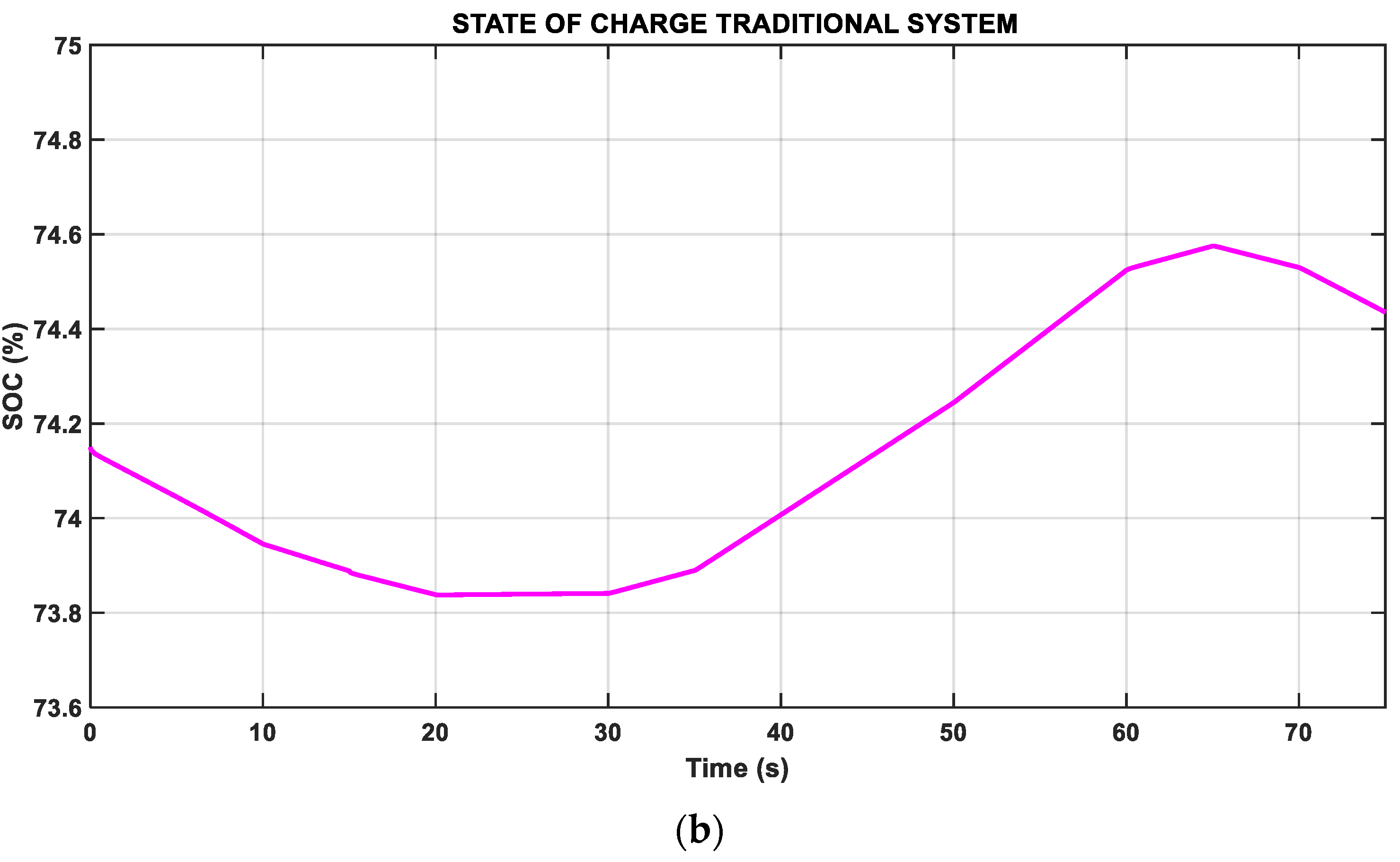
Figure 12b, in the intervals from 40 to 65 s, the battery fails to be fully charged and does not reach the upper limit of the SOC (90%), so at second 65, when the solar power is reduced and the demand increases, the battery delivers according to its discharge capacity.
At second 65, the solar power is reduced and the electrical demand increases; this is supplied by the solar power with 6810 W plus the power generated by the battery, which is not fully charged so it delivers according to its discharge characteristics of 1450 W. Therefore, it is not enough to meet the balance of powers, so the EMS integrates the diesel generator (blue line) that supports with 1740 W to supply the demand. Finally, after 70 s the solar power is reduced, and the diesel generator must increase its supply.
The operating costs produced by the diesel generator in the period time of 60 to 65 s is USD 0.00056 and during 70 to 75 s is USD 0.0014, with a total operating cost of USD 0.002, taking into consideration that the commercial cost of diesel in Ecuador is USD 0.0462/lt.
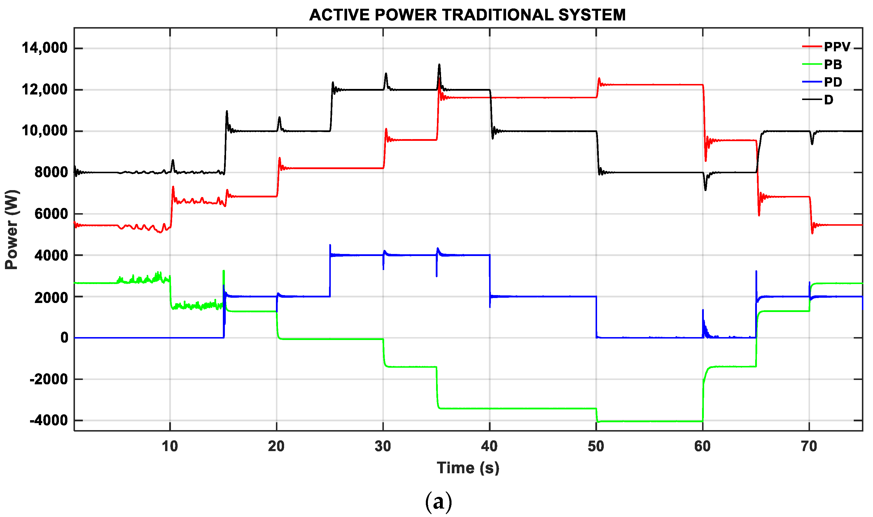
Figure 13 shows the microgrid’s performance without EMS. Figure 13a shows the distribution of active power by the generation units of the microgrid, without including the optimal EMS dispatch; this information is also visible in Table 6. During the interval from 0 to 15 s, the demand (black line) is satisfied by the solar generation (red line) and the battery (green line), without the intervention of the diesel generator (blue line). In addition, in the second 15 s, there is an increase in demand of 10,000 W; the solar power remains the same as the previous operating point and it can be noticed how the battery continues to discharge. However, the diesel generator also starts to deliver a power of 2000 W. In the second 20 s, the solar power increases to 8127 W, but with a demand equal to the previous interval; however, the diesel generator continues to generate 2000 W, unlike the operation with EMS (Figure 12a) in this interval the diesel generator remains off. The operation of the microgrid in the interval from 25 to 40 s shows that the demand is higher than the solar power; in addition, the diesel generator continues delivering the same power of the previous interval, which does not happen in the scenario with EMS because this control calculates the power distribution at a minimum cost, reducing the use of the diesel generator. In the time interval from 40 to 65 s, the demand is completely supplied by the solar power, and because the solar energy is higher than the demand, the surplus energy is stored in the battery, which has negative power, i.e., it becomes a load on the microgrid. Finally, in the last time interval from 65 to 75 s, the demand increases to 10,000 W and the photovoltaic power is reduced; in addition, to supplying the demand the diesel unit delivers 2000 W because there is no controller to properly manage the power. It can be observed that despite there being a variation of photovoltaic power, the diesel generator delivers a constant power. In comparison with the EMS, it can be observed that, in this same time interval, the diesel power is distributed between 65 to 70 s and 70 to 75 s; the photovoltaic power is different so the EMS recalculates and gives the order to the diesel generator to supply the missing power for each case, supplying the demand.
Figure 13b shows how, from 20 s, the battery start with its charging process because the diesel generator starts to supply the missing power to the demand; however, this is not the most economical way to operate the microgrid due to fuel consumption and environmental pollution, despite the battery not being fully charged to its maximum point, so at second 65, when the solar power is reduced and the demand increases, the battery delivers according to its discharge capacity.
The cost of operating the diesel generator without an EMS during the periods of 15 to 25, 40 to 50, and 65 to 75 s is USD 0.00064, respectively, and in the time interval of 25 to 40 s, the cost generated is USD 0.00128, giving a total cost of generation of USD 0.0077.
Implementing the EMS tertiary control working in sliding mode allows us to calculate the optimal solutions for the distribution of power in the microgrid, as shown in Figure 12a. Through real-time measurements of the variables, it is shown that in most of the simulation period, the diesel generator remains deactivated, to minimize costs. This means that the control algorithm does not activate the auxiliary unit, which is reflected in the reduction of operating costs and reduction of environmental pollution, in addition to extending the life of the battery, preventing it from operating at critical points such as overloads or deep discharges, while complying with the power balance to supply the required demand. While the system without EMS, as shown in Figure 13a, supplies the demand, because it does not have the optimal power flow management, the power distribution between the supply units and the battery is not efficient, which is why, in the simulation, the diesel unit supplies energy most of the time. In addition, it does not take care of the operation of the battery because they present deep discharges.

5. Conclusions

This paper presents the design of the primary, secondary, and tertiary controllers for a DC microgrid in island operation. The tertiary control (EMS) allows optimal microgrid management, ensuring optimal power distribution and protecting the lifespan of the battery, using real-time measurement feedback that allows it to react to rapid changes in electrical demand and radiation changes. The primary level corresponds to the voltage and current control for the battery to work in charge and discharge mode, while the photovoltaic power includes an MPPT control based on the incremental conductance algorithm, to take full advantage of the solar resource. In addition, this level includes a droop control to perform the power-sharing of the battery. However, this action causes a deviation in the operating voltage of its nominal value, so a second level of control is implemented to restore voltage. Finally, in the third level of control, an EMS is implemented to determine the power each generating unit must deliver to cover the demand while complying with the technical operating constraints and protecting the lifespan of the battery.
The implemented EMS detects disturbances occurring at lower control levels and operates in the face of rapid changes in radiation and electrical demand. Measurements of battery status and available energy are feedback online by the EMS, and predictions are updated. Thus, the optimal decision of battery usage is more efficient, and the algorithm considers battery operating limit constraints to avoid deep discharges.
The EMS reduces the operating cost by 40% compared to the microgrid without the optimal management system in the evaluating horizon by reducing fuel consumption to supply the demand.
In this research work, the optimal performance of the DC microgrid has been validated by evaluating all levels of control, guaranteeing optimal operation in technical terms, i.e., the use of natural resource and economic terms, by obtaining the minimum operating cost and protecting the lifespan of the battery.
The proposed EMS respects the established SOC limits; therefore, it does not reach deep discharges and mainly presents an optimal operation where the charge and discharge decisions are made by the EMS, i.e., they are taken according to the availability of the natural resource and the minimum cost for the DC microgrid.
Having the design and implementation of the three levels of control allows for identifying the impact that each level has on the EMS and how the disturbances affect the optimal operation. This is why, in our proposal, EMS, by updating the measurements that represent the short-term inputs, can respond to changes detected in the lower levels of control, i.e., when disturbances occur; therefore, the operation of the DC microgrid is integral.
It is determined as future work that within the optimization problem we can add the restrictions of the diesel generator start-up time and modeling of the battery degradation. In addition, we can include the modeling and restriction of the electrical network connected to the microgrid, allowing an increase in the energy supply capacity of the system. From a control point of view, our main future work will focus on a comparison between a centralized and a distributed system of DC microgrids.

Author Contributions

Conceptualization, J.A.B., D.E.P., J.R.L. and D.E.O.; methodology, D.E.P., J.R.L., D.E.O. and C.D.B.; software, J.A.B. and D.E.P.; validation, J.A.B., D.E.P. and J.R.L.; formal analysis, J.A.B., D.E.P., J.R.L., D.E.O. and C.D.B.; investigation, J.A.B. and D.E.P.; resources, J.R.L.; data curation, J.A.B., D.E.P. and J.R.L.; writing—original draft, J.A.B., D.E.P., J.R.L., D.E.O. and C.D.B.; writing—review & editing, J.A.B., D.E.P., J.R.L., D.E.O. and C.D.B.; visualization, J.A.B., D.E.P. and J.R.L.; supervision, J.R.L., D.E.O. and C.D.B.; project administration, J.R.L.; funding acquisition, J.R.L. All authors have read and agreed to the published version of the manuscript.

Funding

This research received no external funding.

Acknowledgments

This work was supported in part by the Universidad de las Fuerzas Armadas ESPE through the Project “Optimal energy management systems for hybrid generation systems”, under Project 2023-pis-03.

Conflicts of Interest

The authors declare no conflict of interest.

Nomenclature

A t Total area of the panel array
A h Ampere-hour
A C Alternating Current
I A Artificial Intelligence
B E S S Battery Energy Storage System
CO 2 Carbon dioxide
C B 1 , C B 2 Capacitors battery
C P V 1 , C P V 2 Photovoltaic capacitors
c o s t G D Cost of diesel power generation
c o s t N S Cost of unsupplied power
D Electrical demand
D C Direct Current
D M P C Decentralized Model Predictive Control
D S M Demand Side Management
d 1 , d 2 Duty cycle
d I P V Derivative of photovoltaic panel current
d P P V Derivative of photovoltaic panel power
d V P V Derivative of photovoltaic panel voltage
E M S Energy Management System
E ( t ) Instantaneous of the BESS power
E ( t 1 ) BESS energy at the previous instant
E 0 Initial energy of the BESS
E V Electric Vehicles
G D Diesel generation unit
G 1 ,   G 2 , G 3 Gates pulses
G P V Photovoltaic generation unit
I B Battery current measurement
I s c Array current panel
I m p Maximum power array current
I P V Photovoltaic panel current
I P V ( t ) Photovoltaic current in instant
I P V ( t Δ t ) Photovoltaic current in a previous instant
I r e f Reference current of the voltage PI controller output
INC Incremental Conductance Algorithm
I G B T Insulated Gate Bipolar Transistor
I r Irradiance
I r ^ Predicted Irradiance
i Prediction horizon
L B Battery Inductance
L P V Photovoltaic Inductor
m 1 ,   m 2 Droop control coefficients
M O G A Multi-Objective Genetic Algorithm
M P C Model Predictive Control
M P P T Maximum Power Point Tracking
n B C BESS performance in charge mode
n B D BESS performance in discharge mode
n P V Photovoltaic panel performance
n i n s t Photovoltaic panel installation performance
NSGA II Non-Dominated Sorting Genetic Algorithm
P B Battery power
P B m a x Maximum power of the BESS
P B C Battery charging power calculated by the EMS
P D Diesel power
P B D Battery discharge power calculated by the EMS
P G D Diesel generation power calculated by the EMS
P G D m i n Minimum diesel power
P G D m a x Maximum diesel power
P N S Power not supplied
P P V Photovoltaic power
P i n v Inverter filter output power
P&OPerturbation and Observation algorithm
P I Integral proportional controller
P W M Pulse Width Modulation
S O C State of Charge
S O C m a x Upper charge limit of the BESS
S O C m i n Lower discharge limit of the BESS
S O C   ( % ) Conditions of initial charge state
T Temperature
t Samples
V Voltage
V E M S Voltage delivered by the EMS
V P V Photovoltaic panel voltage
V P V ( t ) Photovoltaic voltage in instant
V P V ( t Δ t ) Photovoltaic voltage in a previous instant
V b u s Measured Bus DC voltage
V m i n 5% of de nominal voltage
V n o m Nominal voltage of the microgrid
V r e f Droop control output reference voltage
V o c Array tension panel
V m p Maximum power array voltage
X B C The Binary variable of the activation status of the battery charge mode
X B D The Binary variable of the battery discharge mode activation state
X G D The Binary variable of the activation status of the diesel unite
β Secondary control action
Δ I P V Variation of photovoltaic panel current
Δ V P V Variation of photovoltaic panel voltage
Δ d 1 Variation of duty cycle
Δ V m a x Maximum acceptable voltage variation

References

  1. FENERCOM. Basic Guide to Distributed Generation. Madrid, Spain. 2017. Available online: http://www.madrid.org/cs/Satellite?blobcol=urldata&blobheader=application/pdf&blobheadername1=Content-Disposition&blobheadervalue1=filename=GUIA+BASICA+DE+LA+GENERACION.pdf&blobkey=id&blobtable=MungoBlobs&blobwhere=1181215450713&ssbinary=true (accessed on 25 October 2022).
  2. Prats, D.Á.; García, R.A.; Alonso, J.V. Hybrid systems based on renewable energies for power supply to desalination plants. Mech. Eng. 2011, 14, 22–30. [Google Scholar]
  3. Andrade Granja, K.A.A. Optimal Geographically Distributed Micro-Grid Management System to Maximize Energy Sales Based on Demand Response Programs. Bachelor’s Thesis, Salesian Polytechnic University, Quito, Ecuador, 2021. [Google Scholar]
  4. Rey, J.M.; Vera, G.A.; Acevedo Rueda, P.; Solano, J.; Mantilla, M.A.; Llanos, J.; Doris, S. A Review of Microgrids in Latin America: Laboratories and Test Systems. IEEE Lat. Am. Trans. 2022, 20, 1000–1011. [Google Scholar] [CrossRef]
  5. Barrales Alcaín, G. Isolated Microgrids: A Challenge for DSO’s. Bachelor’s Thesis, School of Engineering (ICAI), Madrid, Spain, 2016. [Google Scholar]
  6. Nicanor, Q.; Peraza, A.; Velásquez, M.; Jiménez, E.; Cadena, Á.; Becerra, J.; Ramírez, Á. Isolated Microgrids in La Guajira: Design and Implementation. Eng. Mag. 2019, 55, 60–69. [Google Scholar]
  7. Moya, A.P.; Pazmiño, P.J.; Llanos, J.R.; Ortiz-Villalba, D.; Burgos, C. Distributed Secondary Control for Battery Management in a DC Microgrid. Energies 2022, 15, 8769. [Google Scholar] [CrossRef]
  8. Rodríguez, M.; Salazar, A.; Arcos-Aviles, D.; Llanos, J.; Martínez, W.; Motoasca, E. A brief approach of Microgrids implementation in Ecuador: A review. In Recent Advances in Electrical Engineering, Electronics and Energy, Proceedings of the CIT 2020 Volume 1, Quito, Ecuador, 19–23 October 2020; Springer: Berlin/Heidelberg, Germany, 2020; pp. 149–163. [Google Scholar] [CrossRef]
  9. Navas, F.A.; Gomez, J.S.; Llanos, J.; Rute, E.; Saez, D.; Sumner, M. Distributed predictive control strategy for frequency restoration of microgrids considering optimal dispatch. IEEE Trans. Smart Grid 2021, 12, 2748–2759. [Google Scholar] [CrossRef]
  10. Proano, J.L.; Villalba, D.O.; Saez, D.; Quero, D.O. Economic dispatch for optimal management of isolated microgrids. In Proceedings of the 2016 IEEE 36th Central American and Panama Convention. CONCAPAN 2016, San José, Costa Rica, 9–11 November 2016; pp. 2–7. [Google Scholar] [CrossRef]
  11. Yao, M.; Molzahn, D.K.; Mathieu, J.L. An optimal Power Flow Approach to Improve Power System Voltage Stability Using Demand Response. IEEE Trans. Control Netw. Syst. 2019, 6, 1015–1025. [Google Scholar] [CrossRef]
  12. López Torrez, J.I. Energy Storage Systems from Battery Banks for the Integration of Renewable Energy Sources in DC Microgrids. Bachelor’s Thesis, Technological University of Pereira, Pereira, Colombia, 2015. [Google Scholar]
  13. Fotopoulou, M.; Rakopoulos, D.; Trigkas, D.; Stergiopoulos, F.; Blanas, O.; Voutetakis, S. State of the art of low and medium voltage direct current (Dc) microgrids. Energies 2021, 14, 5595. [Google Scholar] [CrossRef]
  14. Duarte Peñuela, B. Analysis for the Transition of Residential Microgrids from AC Current to DC Current. Bachelor’s Thesis, Universidad de La Salle, Metro Manila, Philippines, 2020. [Google Scholar]
  15. El-Hendawi, M.; Gabbar, H.A.; El-Saady, G.; Ibrahim, E.-N.A. Control y EMS de una microrred conectada a la red con análisis económico. Energies 2018, 11, 129. [Google Scholar] [CrossRef] [Green Version]
  16. Navas-Fonseca, A.; Burgos-Mellado, C.; Gomez, J.S.; Llanos, J.; Espina, E.; Saez, D.; Sumner, M. Distributed Predictive Control using Frequency and Voltage Soft Constraints in AC Microgrids including Economic Dispatch of Generation. In Proceedings of the IECON 2021–47th Annual Conference of the IEEE Industrial Electronics Society, Toronto, ON, Canada, 13–16 October 2021. [Google Scholar] [CrossRef]
  17. Camacho, E.F.; Bordons, C. Predictive Control: Past, Present and Future. Iberoam. J. Autom. Ind. Inform. 2004, 1, 5–28. [Google Scholar]
  18. Saltos-Rodríguez, M.; Ortiz-Villalba, D.; Llanos, J.; Chipantiza-Punguil, C.; Guaita-Rojano, R. Practical Framework for Optimal Planning of Microgrids for Production Processes. In Proceedings of the IEEE 36th Central American and Panama Convention (CONCAPAN XXXVI), San Jose, Costa Rica, 9–11 November 2016; pp. 4–11. [Google Scholar] [CrossRef]
  19. Palma-Behnke, R.; Benavides, C.; Lanas, F.; Severino, B.; Reyes, L.; Llanos, J.; Saez, D. A microgrid energy management system based on the rolling horizon strategy. IEEE Trans. Smart Grid 2013, 4, 996–1006. [Google Scholar] [CrossRef] [Green Version]
  20. Carvajal González, E.E.; Muñoz López, G.J.; Rivera, S. Optimization of microgrid operation considering operating cost, battery life and uncertainty cost of wind energy. Between Sci. Eng. 2019, 13, 24–33. [Google Scholar] [CrossRef] [Green Version]
  21. Ali, S.U.; Waqar, A.; Aamir, M.; Qaisar, S.M.; Iqbal, J. Model predictive control of consensus-based energy management system for DC microgrid. PLoS ONE 2023, 18, e0278110. [Google Scholar] [CrossRef] [PubMed]
  22. Bordons, C.; García Torres, F.; Valverde, L. Optimal Energy Management in Microgrids with Renewable Generation. Iberoam. J. Ind. Autom. Inform. 2015, 12, 117–132. [Google Scholar] [CrossRef] [Green Version]
  23. Parisio, A.; Glielmo, L. Energy efficient microgrid management using Model Predictive Control. In Proceedings of the IEEE Conference on Decision and Control, Orlando, FL, USA, 12–15 December 2011; pp. 5449–5454. [Google Scholar] [CrossRef]
  24. Zuñiga Cortes, F.A.; Caicedo Bravo, E.F.; López Santiago, D.M. Optimal Electric Power Management in a Connected Microgrid, based on the Genetic Algorithm for Multiobjective Optimization MOGA. UIS Eng. Mag. 2017, 15, 17–28. [Google Scholar] [CrossRef] [Green Version]
  25. Ignacio, R.; Bustos, B. Predictive Control for a Micro-Network Coordination System Considering Demand Management. Master’s Thesis, University of Chile, Santiago, Chile, 2022. [Google Scholar]
  26. Trigkas, D.; Gravanis, G.; Diamantaras, K.; Voutetakis, S.; Papadopoulou, S. Energy Management in Microgrids Using Model Predictive Control Empowered with Artificial Intelligence. Chem. Eng. Trans. 2022, 94, 961–966. [Google Scholar]
  27. Bordons, C.; GarciaTorres, F.; Ridao, M.A. Predictive control in interconnected microgrids and with electric vehicles. Iberoam. J. Autom. Ind. Inform. 2020, 17, 240–250. [Google Scholar] [CrossRef]
  28. Sayed, K.; Abo-Khalil, A.G.; Alghamdi, A.S. Optimum resilient operation and control DC microgrid based electric vehicles charging station powered by renewable energy sources. Energies 2019, 12, 4240. [Google Scholar] [CrossRef] [Green Version]
  29. Cuéllar Guarnizo, J.A. Design of a Controller for Maximum Power Point Tracking (MPPT) in Solar Panels. Master’s Thesis, University of Santo Tomás, Bogotá, Colombia, 2019. [Google Scholar]
  30. Álvarez López, R.A.; Manrique, A.A. Implementation of Photovoltaic Generation as a Back-up for Distribution Grid Failures. Colomb. J. Adv. Technol. 2013, 2, 14–19. [Google Scholar]
  31. Acevedo Meza, H.; Mendoza García, J.L.; Sepúlveda Mora, S. MPPT Control Strategies Applied in a DC/DC Boost Converter for PV Systems. Colomb. J. Adv. Technol. 2017, 2, 102–107. [Google Scholar] [CrossRef]
  32. Intriago, S.; Robayo, P.; Llanos, J.; Silva, F.; Gómez, J. Comparison of Control Strategies for Monitoring the Maximum Power Point Tracking of a Photovoltaic Plant. In Proceedings of the 6th IEEE Ecuador Technical Chapters Meeting (ETCM) 2022, Quito, Ecuador, 11–14 October 2022. [Google Scholar] [CrossRef]
  33. Cuzco, R.; Arcos-Aviles, D.; Llanos, J.; Ortíz, D.; Martínez, W. Comparative Analysis of the Performance of Maximum Power Point Tracking Algorithms in Photovoltaic Systems. XV Multidiscip. Int. Congr. Sci. Technol. 2022, 931, 274–289. [Google Scholar] [CrossRef]
  34. El-Shahat, A.; Sumaiya, S. DC-microgrid system design, control, and analysis. Electronics 2019, 8, 124. [Google Scholar] [CrossRef] [Green Version]
  35. Echeverría, N.; Judewicz, M.; Murcia, G.; Strack, J.; González, S. Incremental Conductance MPPT Algorithm with Double Peak. In Proceedings of the ANALES del XXIV Argentine Congress of Automatic Control, AADECA’2014, Buenos Aires, Argentina, 27–29 October 2014; Volume 9. [Google Scholar] [CrossRef]
  36. Vera, J.E.; Bayona, J.F.; Sánchez, R. Maximum power point tracking (SPMP) on solar panels. Vis. Electron. 2014, 8, 50–53. [Google Scholar]
  37. Medina, R.D. Microgrids Based on Power Electronics: Part II: Active and Reactive Power Control. Ingenius 2014, 12, 24–34. [Google Scholar] [CrossRef]
  38. Keshavarzi, M.D.; Ali, M.H. A Novel Bidirectional DC-DC Converter for Dynamic Performance Enhancement of Hybrid AC/DC Microgrid. Electronics 2020, 9, 1653. [Google Scholar] [CrossRef]
  39. Morell, J.M.B. Control of AC/DC and DC/AC Converters for Charging Electric Vehicles. Bachelor’s Thesis, University of Seville, Seville, Spain, 2012. [Google Scholar]
  40. Contreras, J.P. Pulse Width Modulation (PWM) and Vector Modulation (SVM). An Introduction to Modulation Techniques. Lat. Am. Netw. Sci. J. 2005, 1, 70–80. Available online: http://www.doaj.org/doaj?func=abstract&id=256164 (accessed on 26 December 2022).
  41. Lv, J.; Wang, X.; Wang, G.; Song, Y. Research on control strategy of isolated dc microgrid based on soc of energy storage system. Electronics 2021, 10, 834. [Google Scholar] [CrossRef]
  42. Alidrissi, Y.; Ouladsine, R.; Elmouatamid, A.; Errouissi, R.; Bakhouya, M. Constant Power Load Stabilization in DC Microgrids Using Continuous-Time Model Predictive Control. Electronics 2022, 11, 1481. [Google Scholar] [CrossRef]
  43. Llanos, J.; Gomez, J.; Saez, D.; Olivares, D.; Simpson-Porco, J. Economic dispatch by secondary distributed control in microgrids. In Proceedings of the 21st European Conference Power Electronics and Applications, EPE 2019 ECCE Europe, Genova, Italy, 3–5 December 2019; pp. 1–10. [Google Scholar] [CrossRef]
  44. Moreno, S.R. Energy Management of a Microgrid through Model Predictive Control. Bachelor’s Thesis, University of Sevilla, Sevilla, Spain, 2019. [Google Scholar]
  45. Segovia, J.A.; Toaquiza, J.F.; Llanos, J.R.; Rivas, D.R. Meteorological Variables Forecasting System Using Machine Learning and Open-Source Software. Electronics 2023, 12, 1007. [Google Scholar] [CrossRef]
Figure 1. DC Microgrid configuration diagram.
Energies 16 02912 g001
Figure 2. Control architecture.
Energies 16 02912 g002
Figure 3. Control design for the photovoltaic system.
Energies 16 02912 g003
Figure 4. Characteristic curves of the photovoltaic panel: (a) I-V curve; (b) P-V curve.
Energies 16 02912 g004
Figure 5. Diagram of the MPPT incremental conductance algorithm.
Energies 16 02912 g005
Figure 6. Bidirectional Converter “Buck–Boost”.
Energies 16 02912 g006
Figure 7. Control strategy for the storage system.
Energies 16 02912 g007
Figure 8. Voltage restorer secondary control strategy.
Energies 16 02912 g008
Figure 9. MPC Control Schematic.
Energies 16 02912 g009
Figure 10. Irradiance profile.
Energies 16 02912 g010
Figure 11. Demand profile.
Energies 16 02912 g011
Figure 12. Microgrid performance with EMS; (a) Active Power Microgrid, (b) SOC of BESS.
Energies 16 02912 g012
Figure 13. Microgrid performance without EMS: (a) Active Power Microgrid, (b) SOC of BESS.
Energies 16 02912 g013aEnergies 16 02912 g013b
Table 1. Photovoltaic panel parameters.
DescriptionParameterValue
Array tension panel V o c 49.68 V
Maximum power array voltage V m p 40.98 V
Array current panel I s c 14.01 A
Maximum power array current I m p 13.42 A
Table 2. BESS parameters.
DescriptionParameterValue
VoltageV36 V
Ampere-hourAh10 Ah
Conditions of initial charge state SOC (%)75%
The upper limit of a state of chargeSOCmax90%
The lower limit of discharge stateSOCmin40%
Table 3. Characteristics of the Diesel Generator.
DescriptionParameterValue
Minimum diesel power P G D m i n 600 W
Maximum diesel power P G D m a x 6000 W
Cost diesel c o s t G D USD 0.046/lt
Table 4. Characteristics of the converters.
DescriptionParameterValue
Photovoltaic capacitor 1 C P V 1 1800 μ F
Photovoltaic capacitor 2 C P V 2 18,000 μ F
Photovoltaic inductor L P V 1.7 mH
Capacitor 1 battery C B 1 390.63 μ F
Capacitor 2 battery C B 2 390.63 μ F
Battery inductance L B 9 mH
Nominal voltage of Load V n o m 48 V
Table 5. Active Power microgrid with EMS.
ItemTime (s) P P V (W) P B (W) P D (W) D (W)
10–55395260508000
25–105395260508000
310–156720128008000
415–2067203280010,000
520–2581271873010,000
625–3081273873012,000
730–3594832517012,000
835–4011,452548012,000
940–4511,452−1452010,000
1045–5011,452−1452010,000
1150–5512,059−405908000
1255–6012,059−405908000
1360–659317−131708000
1465–7068101450174010,000
1570–755448251430110,000
Table 6. Active Power microgrid without EMS.
ItemTime (s) P P V   (W) P B (W) P D   (W) D (W)
10–55395260508000
25–105395260508000
310–156720128008000
415–2067201280200010,000
520–258127−127200010,000
625–308127−127400012,000
730–359483−1483400012,000
835–4011,452−3452400012,000
940–4511,452−3452200010,000
1045–5011,452−3452200010,000
1150–5512,059−405908000
1255–6012,059−405908000
1360–659317−131708000
1465–7068101190200010,000
1570–7554482552200010,000
Disclaimer/Publisher’s Note: The statements, opinions and data contained in all publications are solely those of the individual author(s) and contributor(s) and not of MDPI and/or the editor(s). MDPI and/or the editor(s) disclaim responsibility for any injury to people or property resulting from any ideas, methods, instructions or products referred to in the content.

