Article

An SMC-MRAS Speed Estimator for Sensor-Less Control of DFIG Systems in Wind Turbine Applications

by
Mwana Wa Kalaga Mbukani
*,
Michael Njoroge Gitau
and
Raj Naidoo
Department of Electrical, Electronic and Computer Engineering, University of Pretoria, Pretoria 0002, South Africa
*
Author to whom correspondence should be addressed.
Energies 2023, 16(6), 2633; https://doi.org/10.3390/en16062633
Submission received: 17 February 2023 / Revised: 7 March 2023 / Accepted: 9 March 2023 / Published: 10 March 2023
(This article belongs to the Section F3: Power Electronics)

Abstract

:
A sliding mode control-based model reference adaptive system (SMC-MRAS) estimator for sensor-less control of doubly fed induction generator (DFIG) systems in wind turbine applications is proposed in this paper. The proposed SMC-MRAS estimator uses the rotor current as a variable of interest. The proposed SMC-MRAS estimator has the advantage of being immune to machine parameter variations. The SMC parameters are designed using the Lyapunov stability criteria. The performance of the proposed SMC-MRAS estimator is validated using simulations in MATLAB/SIMULINK. A comparative study between the proposed SMC-MRAS estimator and the PI-MRAS estimator is also conducted to demonstrate the superiority of the proposed SMC-MRAS estimator.

1. Introduction

In the last few decades, there has been a sharp rise in wind power generation worldwide due to the need to reduce the carbon footprint. The doubly fed induction generator (DFIG) is one of the most popular wind turbine generators due to the fact that its back-to-back converters are partially rated [1,2,3,4,5,6,7]. The DFIGs are mostly controlled using the vector control technique due to its simplicity [5,7]. The vector control strategy requires d q -transformation. The transformation of the rotor quantities of the DFIG requires knowledge of the rotor speed/position [7]. The information on the rotor speed/position is acquired by the rotary encoder. However, the rotary encoder is known to have a high failure rate in offshore areas, which can lead to the failure of the whole wind energy conversion system (WECS) and the interruption of the electric power supply.
Several estimation techniques have been proposed in the literature to address this issue [5]. The estimation techniques can be mainly grouped into two categories. There are saliency-based estimation techniques and model-based estimation techniques [5]. The saliency-based estimation techniques aim at estimating the rotor speed/position from the DFIG model at frequencies that are higher than the fundamental frequency [5]. In fact, the rotor speed/position is extracted from the position of the related inductance under high-frequency signal injections [8,9,10]. Hence, the saliency-based estimation methods are suitable for start-up and standstill operating conditions.
The model-based estimation techniques aim at extracting the rotor speed/position from the DFIG model at the fundamental frequency [5]. They are mostly suitable for medium- and high-speed operating conditions. Several types of model-based estimation techniques have been proposed in the literature. One can distinguish the model-based estimation techniques based on the sliding mode observers (SMO) [11,12,13,14], the extended Kalman filters (EKF) [15], the unscented Kalman filters [16,17], the phase-locked loop (PLL) [18], the model-reference adaptive systems (MRAS) [19,20,21,22,23,24,25,26,27,28,29,30,31,32,33,34,35], the disturbance observers [36,37,38] and others. The MRAS estimators are the most popular rotor speed/position estimators due to their simplicity and direct physical interpretation. The MRAS estimators can be designed based on several variables of interest, such as the back-EMF, the stator current, the rotor current, electromagnetic torque, the stator flux and the rotor flux [21,30,31]. It was shown in [30] that the MRAS estimator with the rotor current as a variable of interest had a better estimation performance. The MRAS estimators are mainly composed of a reference model, an adjustable model and an adaptive mechanism. The most developed adaptive mechanisms make use of the PI controller with constant gains. The PI controllers are well known to provide acceptable dynamic performance and steady-state performances. However, their main disadvantage is their narrow bandwidth. Further, while tuning the PI gains, a trade off between the oscillations, overshoot and damping is necessary. To address these shortcomings, several other types of adaptive mechanisms are presented in the literature, such as the finite-set model predictive control (FS-MPC) [25], sliding mode control [26] and the neural network [27,32].
In [25], a limited-position set (LPS) model-reference adaptive system estimator for the sensor-less control of the DFIGs-based wind energy conversion systems was proposed. The LPS-MRAS estimator uses the rotor current as a variable of interest. Further, it employs an algorithm that aims to provide a constant number of angles for the rotor angle of the DFIG. In [26], a MRAS estimator that uses the sliding mode control as an adaptive mechanism is proposed for the single-phase induction motor. The sliding mode control is well known for its robustness against any disturbances and machine parameter variation. The MRAS proposed in [26] uses the rotor flux as a variable of interest. In [27], a stator current-based model reference adaptive systems speed estimator for the sensor-less control of induction motor drives is investigated. The adaptive model uses a two-layer, online trained neural network stator current observer in order to use a pure integrator.
In this paper, an SMC-MRAS estimator for the sensor-less control of DFIG-based WECS is proposed. The proposed SMC-MRAS estimator uses the rotor current as a variable of interest. It has the advantage of being immune to machine parameter variation, and it is robust against any disturbances. In addition, a comparative study between the PI-MRAS estimator proposed in [34] and the proposed SMC-MRAS estimator is conducted in this paper. The parameters of the adaptive mechanism of the proposed SMC-MRAS estimator are determined using the Lyapunov stability criteria. Hence, the contributions of this paper can be summarized as follows.
1.
The proposed SMC-MRAS estimator uses the rotor current as a variable of interest.
2.
The use of the Lyapunov stability criteria in order to determine the SMC gains of the SMC-MRAS estimator.
3.
The use of the proposed SMC helps to reduce the sensitivity to machine parameter variations.
4.
A comparative study between the proposed SMC-MRAS estimator and the PI-MRAS estimator discussed in [34] is presented. It is shown that the estimation performance from the proposed SMC-MRAS estimator is better under machine parameter variations and under a rapid change in the wind speed.
The performance of the proposed SMC-MRAS estimator for the sensor-less vector control strategy is validated using MATLAB/SIMULINK. The superiority of the proposed SMC-MRAS estimator over the PI-MRAS estimator is validated under various operating conditions using simulation results.
The remainder of the paper is organised as follows. The modelling of the DFIG system is discussed in Section 2, while the sensor-less control strategy is discussed in Section 3. The design of the proposed SMC-MRAS estimator is discussed in Section 4, while that of the PI-MRAS estimator is discussed in Section 5. The results are discussed in Section 6. The conclusions are drawn in Section 7.

2. DFIG Modelling

In this section, the model of the DFIG is discussed. The expressions of the stator and rotor space vector voltages in the stationary reference frame are given by [1,2,3,5,6,7]
u s = R s i s + d ϕ s d t u r = R r i r + d ϕ r d t j ω r ϕ r ,
where u s is the stator voltage space vector while u r is the rotor voltage space vector. i s and i r are the space vector stator current and space vector rotor current, respectively. ϕ r and ϕ s are the rotor and stator flux linkage vectors, while ω r = P Ω m is the electrical angular speed. P and Ω m are pole-pairs and the mechanical speed.
The expressions of the stator and rotor flux linkages in the stationary reference frame are given by [1,2,3,5,6,7]
ϕ s = L s i s + L m i r ϕ r = L r i r + L m i s ,
The expressions of stator active and reactive powers are given by [1,2,3,5,6,7]
P s = 3 u s i ¯ s Q s = 3 u s i ¯ s ,
where P s and Q s are the stator active power and the stator reactive power, respectively. The superscript - denotes the complex conjugate. The mechanical equation of the DFIG is given by [1,2,3,5,6,7]
τ e τ L = J d Ω m d t ,
where τ e , τ L and J are the electromagnetic torque, the load torque and the inertia, respectively. The relationship between the synchronous angular speed and the rotor angular speed is given by [1,2,3,5,7]
ω s = ω g ω r ,
where ω s , ω g and ω r are the slip angular speed, the synchronous angular speed and the rotor speed. The expression of the slip is given by [1,2,3,5,7]
s = ω g ω r ω g ,
where s is the slip of the DFIG. The slip angle, θ s , is given by [1,2,3,5,7]
θ s = θ g θ r ,
where θ g is the stator voltage angle and θ r is the rotor angle. The stator/grid voltage angle is calculated using a phase-locked loop function.

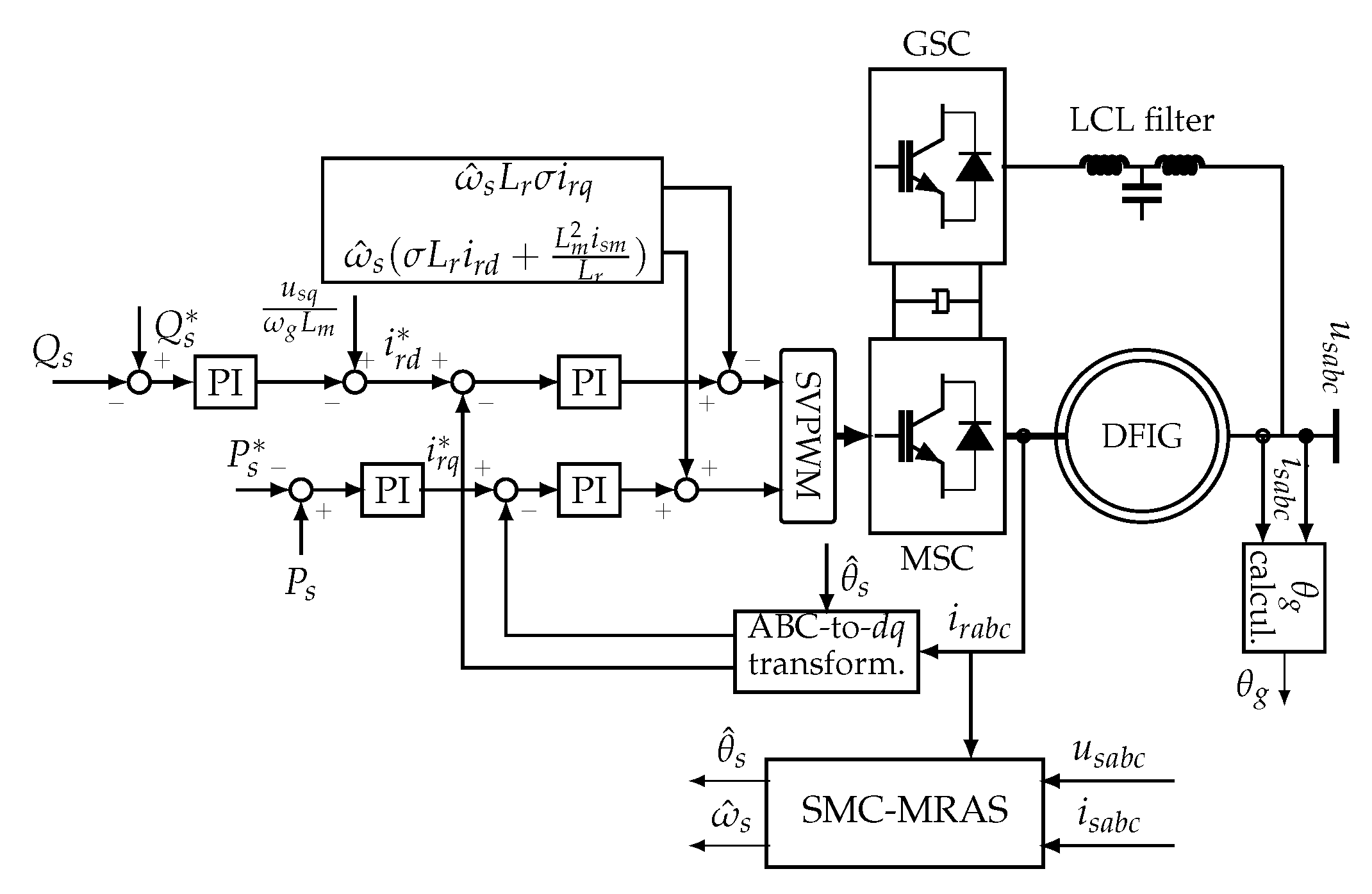
3. Sensor-Less Control Strategy

The schematic of the proposed sensor-less control strategy is depicted in Figure 1. The proposed control strategy uses voltage-oriented control with the q-axis of the synchronous reference frame being aligned along the grid voltage vector. The control strategy is composed of two control loops and it is implemented in the synchronous d q -reference frame. The outer control loop is dedicated to the control of the active stator power, P s , while the two inner control loops are dedicated to the control of the d-axis and q-axis rotor currents. The stator quantities are transformed into the synchronous d q -reference frame using the calculated stator/grid voltage angle, θ g . The rotor quantities are transformed into the synchronous d q -reference frame by using the estimated slip angle, θ ^ s . The estimated slip angle is calculated by either the SMC-MRAS speed estimator or the PI-MRAS estimator as a comparative study is conducted.

3.1. Reference Active and Reactive Powers

In the outer control loop, the reference stator active power, P s , is calculated such that the maximum power point tracking is achieved. The estimated rotor speed, ω ^ r , is used for the calculation of the reference stator active power. It is calculated as
ω ^ r = ω g ω ^ s ,
where ω g is the synchronous speed and the superscript ^ denotes the estimated values. The reference active power is given by [6,7]
P s = x o p t ω ^ r 3 ,
with
x o p t = C P o p t ρ π R 5 2 λ o p t 3 m 3 P 2 ,
where ρ is the air density, R is the radius of the blade, C P o p t is the optimum power coefficient, m is the gear ratio and λ o p t is the optimum tip-speed ratio.
The reference reactive power, Q s , is set to zero so that the DFIG system operates under the unity power factor at the stator side. The reference reactive power is given by
Q s = 0 .

3.2. Outer Control Loops

The reference stator active power, P s , is compared to the measured stator active power, then fed into the outer PI controller. The calculated stator active power, P s , is determined using the expression in (3). Applying VOC on (3), yields
P s = L m u s q L s ω g i r q Q s = L m u s q L s u s q ω g L m i r d ,
where u s q is the q-axis stator voltage. From (12), it can be seen that the stator active power can be regulated using the q-axis rotor current while the stator reactive power can be controlled using the q-axis rotor current. Further, the outer transfer function can be deduced. Hence, the PI controllers are in the outer loop for the regulation of the stator active and reactive powers, as depicted in Figure 1. The outputs of the outer PI controllers are the reference q-axis rotor current, i r q , and the reference d-axis rotor current, i r d . The outer PI controller gains are designed using pole placement, knowing that the bandwidth of the outer PI controller should be at least ten times slower than the inner PI controller.

3.3. Inner Control Loops

Applying the VOC to (1), the d-axis and q-axis rotor voltages are given by
u r d = R r i r d + σ L r d i r d d t σ ω s L r i r q c o m p e n s a t i o n t e r m s u r q = R r i r q + σ L r d i r q d t + ω s ( σ L r i r q + L m 2 L s i s m c o m p e n s a t i o n t e r m s ) ,
where the σ = 1 L m 2 L s L r and i s m is the magnetizing current. From (13), the inner transfer function can be deduced. The reference q-axis rotor current is compared to the measured q-axis rotor current, then fed into the inner PI controller, which controls the q-axis rotor current. The reference d-axis rotor current, i r d , is set to zero in order to guarantee unity power factor. The reference d-axis rotor current is compared to the measured rotor current, then fed into the second inner PI controller. The outputs of the inner PI controllers are compensated for using the compensation terms to obtain the reference rotor voltage to be fed into the space vector PWM function, which provides the actuating signals to the power switches of the machine-side converter (MSC). The estimated stator speed, ω ^ s , is used in the compensation terms. The inner controller for both inner loops is the same due to having the same transfer functions. The inner PI gains are designed using pole placement.

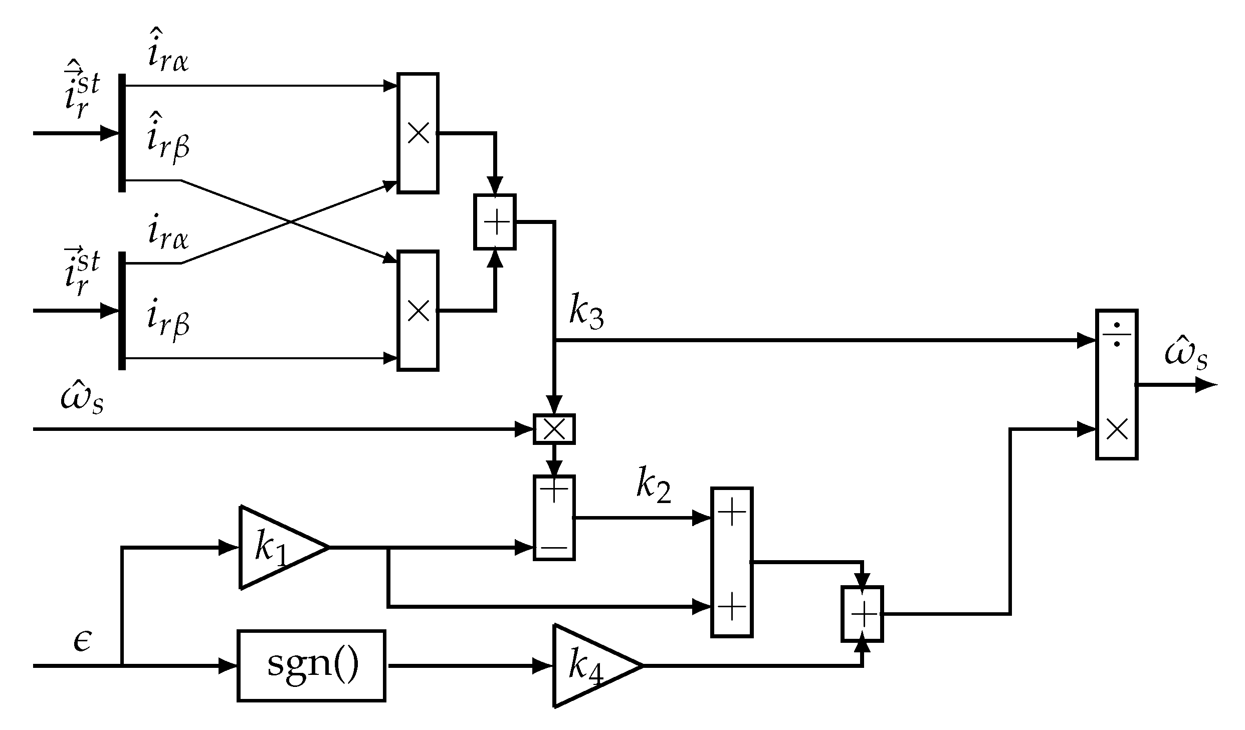
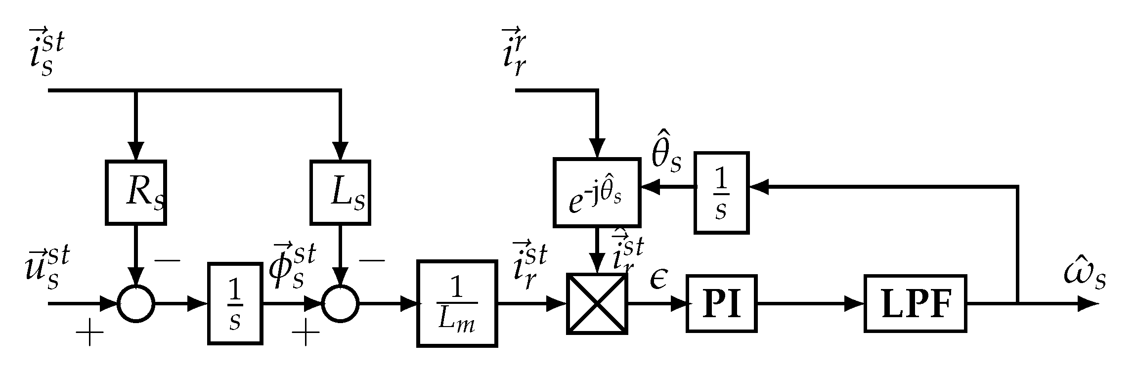
4. SMC-MRAS Estimator Design

The main contribution of this paper is discussed in this section. The design of the proposed SMC-MRAS estimator is discussed, and the parameter of the proposed sliding mode control is also presented.

4.1. Proposed SMC-MRAS Estimator

The proposed SMC-MRAS estimator is depicted in Figure 2. It is composed of the reference model, the adjustable model and the adaptive mechanism. The rotor current is the variable of interest. The measured stator voltage, u s s t , the measured stator current, i s s t , and the measured rotor current, i r r , are the inputs of the proposed SMC-MRAS estimator. The estimated slip speed/position is obtained by comparing the measured rotor current referred to the stationary reference frame, i ^ r s t , and the calculated rotor current, i r s t . The superscript st denotes the quantities referred to as the stationary reference frame. The error, ϵ , obtained from this comparison is driven to zero by the proposed SMC-based adaptive mechanism. The output of the SMC-based adaptive mechanism is the estimated slip speed, ω ^ s . The latter is integrated to obtain the estimated slip angle, θ ^ s . The estimated slip angle is used to refer the measured rotor current to the stationary reference frame.

4.2. Reference Model

The output of the reference model is the calculated rotor current in the stationary reference frame, i r s t . From (2), the expression of the calculated rotor current in the stationary reference frame is given by
i r s t = 1 L m ϕ s s t L s i s s t
The stator flux, ϕ s s t , is calculated using the expression in (1) as
ϕ s s t = 0 t u s s t R s i s s t d τ .
The reference model is built based on (14) and (15).

4.3. Adjustable Model

The output of the adjustable model is the estimated rotor current referred to the stationary reference frame, i ^ r s t . The estimated rotor current in the stationary reference frame is given by
i ^ r s t = i r r e j ( θ ^ s )
where θ ^ s is the estimated slip angle.

4.4. Design of the SMC-Based Adaptive Mechanism

The proposed SMC is depicted in Figure 3. The error, ϵ , to be driven to zero by the SMC-based adaptive mechanism, is given by
ϵ = i ^ r s t × i r s t = i ^ r α i r β i r α i ^ r β = | i ^ r s t | | i r s t | sin ( θ err ) ,
where the subscript α and β denote quantities referring to the α -axis and β -axis of the stationary reference frame, respectively; θ err is the angle between i ^ r s t and i r s t . The aim of the proposed SMC is to drive θ err to zero. Once θ err is zero, it means that i ^ r s t and i r s t are equal, and ω s and θ s can be extracted.
Assume that the error in (17) is driven to zero. This means that the estimated rotor current converges with the calculated rotor current. The first derivative of the estimated rotor current is then given by
d i ^ r s t d t = j ω ^ s i ^ r s t ,
where ω ^ s = d θ ^ s d t . Equation (18) can be rewritten as
d i ^ r α d t = ω ^ s i ^ r β d i ^ r β d t = ω ^ s i ^ r α ,
The sliding surface, S, can be defined as
S = k 1 ϵ ,
where k 1 is a gain that is determined based on the Lyapunov stability criteria and S is the sliding surface. To enforce the sliding motion, the first derivative of the sliding surface should be given by
d S d t = S = 0 .
From (21), it can be seen that the time derivative of the error will decay exponentially as
d ϵ d t = k 1 ϵ .
The derivative of the SMC-MRAS error is given by
d ϵ d t = d i r α d t i ^ r β + i r α d i ^ r β d t d i ^ r α d t i r β i ^ r α d i r β d t .
Substituting (19) into (23), yields
d ϵ d t = d i r α d t i ^ r β i ^ r α d i r β d t + ( i r α i ^ r α + i ^ r β i r β ) ω ^ s .
The proposed SMC-based adaptive mechanism is constructed based on (24) being equal to (22). This is performed in order to guarantee the convergence of the system trajectory [26]. It yields
ω ^ s = k 2 + k 1 ϵ k 3 + k 4 k 3 sgn ( S ) .
It can be seen that the proposed SMC has two components. A linear component ( k 2 + k 1 ϵ k 3 ) and a non-linear component ( k 4 k 3 sgn ( S ) ). k 1 , k 2 , k 3 and k 4 are the gains of the proposed SMC to be determined. Compared to the sliding control law presented in [26], in this paper, the coefficient of the non-linear component, k 4 , is constant. This has the advantage of being simple to implement. The estimated slip angle can be deduced by integrating the estimated slip angle as
θ ^ s = 0 t ω ^ s d t .

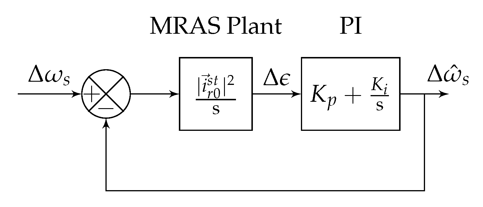
4.5. Stability Analysis

The Lyapunov stability criteria are used to determine k 1 and k 4 . The Lyapunov function is chosen as
V = 1 2 S 2 .
It is clear that V > 0 . Differentiating the Lyapunov function, V, with regards to time, yields
d V d t = S d S d t .
Substituting (20) into (28) yields
d V d t = k 1 S d ϵ d t .
Substituting (20) and (22) into (29) yields
d V d t = k 1 S 2 .
It is clear from (30) that the first derivative of the Lyapunov function is negative when k 1 and k 4 are positive and greater than zero. Hence, the Lyapunov stability criteria are met based on (26) and (30). The value of k 1 and k 4 should also be chosen to be as low as possible such that the noise in the estimated slip speed is kept low. The selection of k 1 and k 4 presents a trade-off between the noise in the estimated slip speed and the robustness against the disturbance. Higher values of k 1 and k 4 lead to higher estimation performance with an increase in the noise, while lower values of k 1 and k 4 lead to lower estimation performance with a decrease in the noise.

4.6. Determination of k 2 and k 3

In order to reach the designated surface or force the convergence of the system trajectory, the expression of k 3 should be calculated from (24), that is,
k 3 = i r α i ^ r α + i ^ r β i r β .
The selection of the expression of k 3 , as shown in (31), forces the output of the proposed SMC to be equal to the estimated slip speed. Further, from (24), k 2 should be chosen such that it contains terms including the first derivative of the calculated rotor current. Therefore, the extraction of the estimated slip speed is also forced by determining the expression k 2 based on (25), that is
k 2 = k 3 ω ^ s k 1 ϵ .

4.7. First-Order Filter Design

A low-pass filter is required in order to reduce the chattering effect introduced by the sliding mode control. It is important to note that the cut-off frequency, ω c , should be large enough in order to reduce the delay in the estimation performance. A cut-off frequency of about ω c = 100 rad/s is deemed to be acceptable.

5. PI-MRAS Estimator

In this section, the PI-MRAS estimator proposed in [34] is discussed. The PI-MRAS estimator is depicted in Figure 4. In order to guarantee a fair comparative study, the PI-MRAS estimator also uses the rotor current as the state variable. The reference model of the PI-MRAS estimator is also based on (2). The calculated rotor current is then calculated as follows;
i r s t = 1 L m ϕ s s t L s i s s t
where ϕ s s t is also calculated from (1) as,
ϕ s s t = 0 t u s s t R s i s s t d τ .
The error of the PI-MRAS estimator is also calculated in the same way as the one for the proposed SMC-MRAS estimator. Hence, the error to be fed into the adjustable mechanism is given by
ϵ = i ^ r s t × i r s t = i r α i ^ r β i ^ r α i r β = | i ^ r s t | | i r s t | sin ( θ err ) .
As discussed above, the adaptive mechanism (in this case, a PI controller) aims at reducing the θ err . The small signal model of (35) with the assumptions that around the operating point (which is when the machine operates at rated conditions), i ^ r 0 s t = i r 0 s t , ω s 0 = ω ^ s 0 and θ err = 0 . The subscript 0 denotes values of quantities at nominal operating conditions. As in [31], when (35) is linearised using a small signal model, it yields
Δ ϵ = | i r 0 s t | 2 cos ( θ err 0 ) Δ θ err .
Δ θ err is given by
Δ θ err = Δ ω s Δ ω ^ s s ,
where s is the Laplace operator. With the above-mentioned assumption of θ err = 0 and substituting (37) into (36) yields
Δ ϵ = | i r 0 s t | 2 Δ ω s Δ ω ^ s s .
The expression in (38) is the plant of the MRAS estimator when the small signal model is used. The closed-loop transfer function can then be formed, as shown in Figure 5. It is important to note that the MRAS plant shown in Figure 5 is dependent on the operating conditions. From (33), it can be seen that the machine parameter variations can affect the MRAS plant. The gains of the PI controller are tuned using pole placement.

6. Simulation Results

In this section, a thorough comparative study between the proposed SMC-MRAS estimator and the PI-MRAS estimator is conducted using MATLAB/SIMULINK. The comparative study is conducted under the steady change in the rotor speed, the step change in stator active power due to the change in the rotor speed and the change in machine parameters ( R s , L s and L m ). The machine parameters are listed in Table 1. The controller parameters are listed in Table 2.

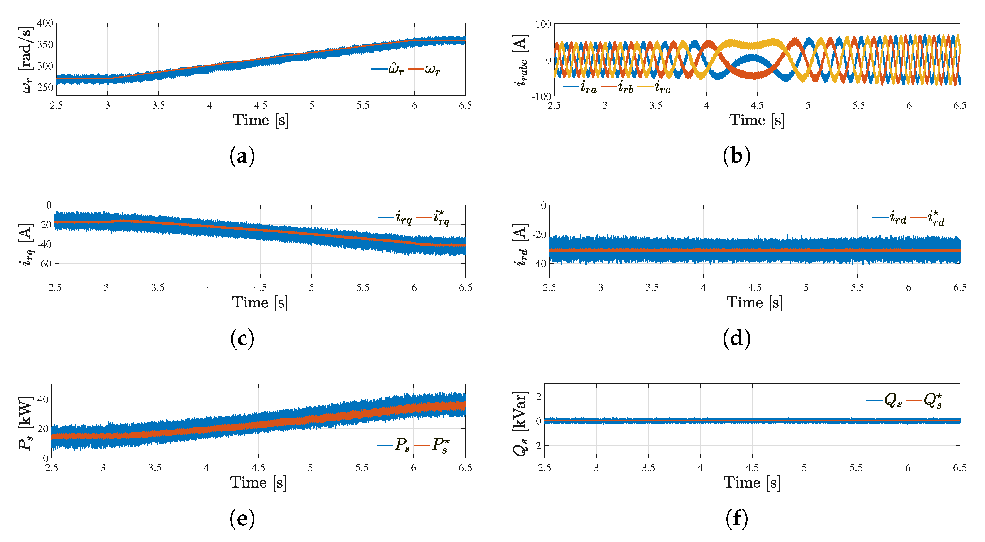
6.1. Performance of the SMC-MRAS-Based Sensor-Less Control Strategy

The performance of the proposed sensor-less control strategy from sub-synchronous to super-synchronous operating conditions is shown in Figure 6. From t = 2.5 s to t = 3.1 s, the DFIG operates at sub-synchronous speed with a rotor speed of 270 rad/s, as shown in Figure 6a. It can be seen that the estimated rotor speed tracks the measured rotor speed. The three-phase current is depicted in Figure 6b, where it can be seen that it pulsates at slip frequency. The q-axis rotor current is maintained at about −20 A while the d-axis rotor current is kept at −29 A, as shown in Figure 6c,d, respectively. This is performed so that the DFIG generates the active stator power that corresponds to the reference stator active power, that is 19 kW. The DFIG also operates under the unity power factor at the stator side, as depicted in Figure 6e,f, respectively. The magnetisation of the DFIG is performed through the rotor side. This is shown by having the d-axis rotor current different to zero.
From t = 3.1 s to t = 6 s, the rotor speed is increased steadily from 270 to 350 rad/s, as can be seen in Figure 6a. It can be seen that the estimated rotor current and the measured rotor speed converge. As the DFIG transitions from sub-synchronous to super-synchronous operating conditions, the change in sequence as well as the increase in the rotor current magnitude, can be seen in Figure 6b. In Figure 6c, the q-axis rotor current is seen to increase with the steady increase in the rotor speed, as it is used to regulate the stator active power (the stator voltage reference is a function of the cubic of the estimated rotor speed). The d-axis rotor current is still kept constant even when the rotor speed is increasing to allow the DFIG operations under the unity power factor, as shown in Figure 6d. The stator active power increases with the increase in the rotor speed to reach the rated power of 37.3 kW at t = 6 s, as shown in Figure 6e. The stator active power is kept at zero, as it can be seen in Figure 6f. From t = 3.1 s to t = 6 s, the overall performance of the proposed sensor-less control strategy is similar to the performance recorded from t = 2.5 s to t = 3.1 s.

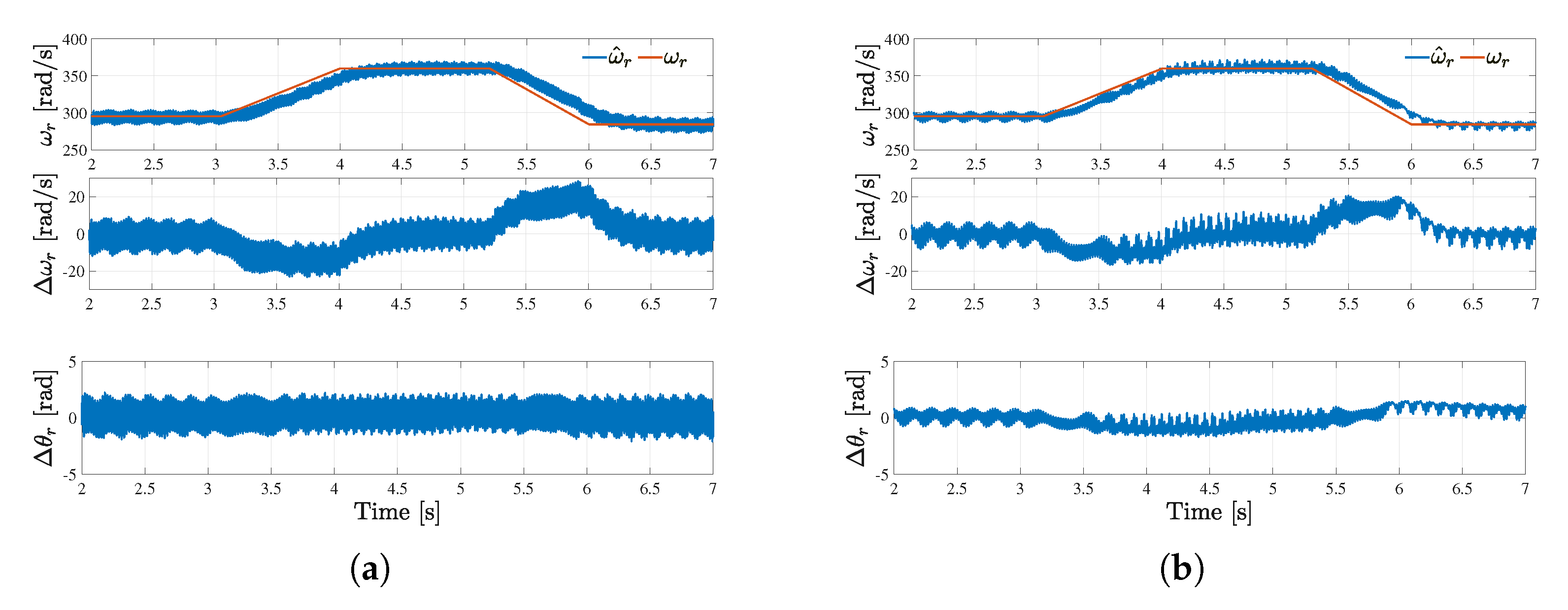
6.2. Performance under Steady Change in Rotor Speed

The performances of the proposed SMC-MRAS estimator and that of the PI-MRAS estimator under the steady change in the rotor speed from synchronous to super-synchronous operating conditions are presented in Figure 7. From top to bottom in Figure 7a,b, the estimated rotor speed and the measured rotor speed, the rotor speed error and the rotor angle error are presented. These quantities are captured while using either the proposed SMC-MRAS estimator or the standard MRAS estimator.
From t = 2 s to t = 3 s , the DFIG operates with a constant rotor speed of about 270 rad/s. The rotor speed converges to the estimated rotor speed, as can be seen in Figure 7a,b. Both the SMC-MRAS and the PI-MRAS estimators perform well under constant rotor speed as the rotor speed error and the rotor angle error for both converge to zero.
From t = 3 s to t = 6 s , the rotor speed increased steadily from 270 to 360 rad/s. The speed error of both MRAS estimators is less than 20 rad/s, which is satisfactory. The rotor angle error for both speed estimators converges to zero to confirm the fact that the performance of both MRAS estimator is comparable.
From t = 6 s to t = 7 s , the DFIG operates under super-synchronous operating conditions with a speed of 360 rad/s. The performance of both MRAS estimators is similar and satisfactory.

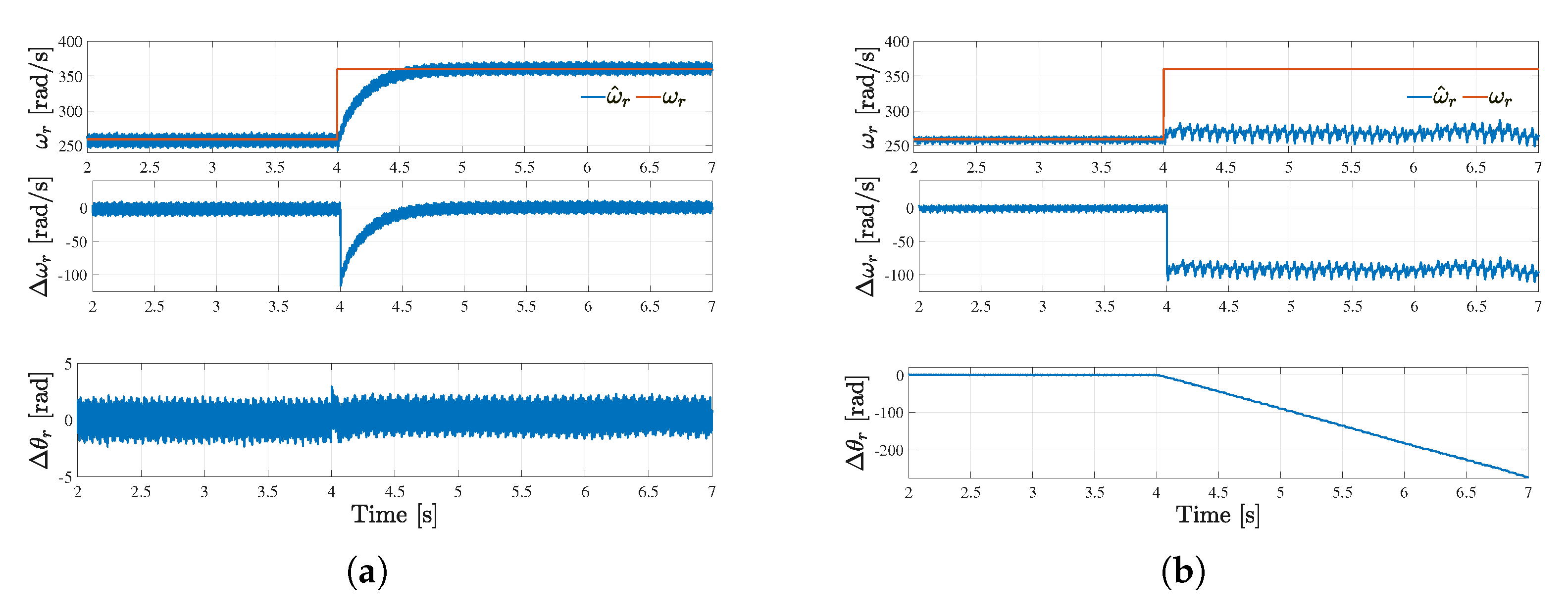
6.3. Performance under Step Change in the Reference Stator Active Power P s

The performances of both MRAS estimators under a sudden change in the stator active power are presented in Figure 8. At t = 4 s, it can be seen that there is a step change in the speed with the expression of the stator active power being P s = x o p t ω r 3 , as discussed in the control strategy section. The rotor speed is suddenly changed from 255 to 315 rad/s. It can be seen in Figure 8a that the estimated rotor speed from the proposed SMC-MRAS estimator converges towards the measured rotor speed after less than 0.5 s while the estimated speed from PI-MRAS estimator converges to the actual speed after 1 s, as shown in Figure 8b.
The maximum rotor speed errors from both MRAS estimators are about 80 rad/s, as the step is about 100 rad/s. The rotor angle error from the proposed SMC-MRAS estimator has a maximum error of less than 5 rad during the step change. It can also be seen that the rotor angle error converges to zero for t ≠ 4 s while the rotor angle error from the PI-MRAS estimator diverges from zero for t ≠ 4 s. This demonstrates the superiority of the proposed SMC-MRAS estimator over the PI-MRAS estimator during the step change in the rotor speed/ stator active power.

6.4. Performance under Machine Parameter Variations (1.3 R s )

The performances under the rapid change in the rotor speed with an increase of 30% of the stator resistance R s of both MRAS estimators are presented in Figure 9. From t = 2 s to t = 3 s, both MRAS estimators perform well during the steady state operation as the rotor speed errors converge to zero. The rotor angle errors converge to zero during this period. From t = 3 s to t = 4 s, the DFIG accelerates to reach a speed of 360 rad/s. The maximum rotor speed errors from both MRAS estimators is about 20 rad/s, as can be seen in Figure 9a,b. The rotor angle error from the SMC-MRAS estimator converges to zero, while the one from the PI-MRAS estimator has a maximum error of about 3 rad.
From t = 4 s and t = 5.25 s, the DFIG operated under super-synchronous operating conditions with a rotor speed of 360 rad/s. Both MRAS estimators perform well with their rotor speed errors and the rotor angle errors converging to zero. From t = 5.25 s and t = 6 s, DFIG decelerates to reach a rotor speed of 300 rad/s. From t = 6 s and t = 7 s, the DFIG operates at 300 rad/s. The performances of both MRAS estimators is similar to the performances during the period of t = 2 s and t = 4 s.

6.5. Performance under Machine Parameter Variations

In Figure 10, the performance of both MRAS estimators are investigated under the sudden change in the rotor speed while the stator inductance and the mutual inductance are varied to mimic the machine parameter variation. In Figure 10a,b, the performances of the SMC-MRAS estimator and the PI-MRAS estimator are shown, respectively.
At t = 4 s, the rotor speed is suddenly changed from 260 to 360 rad/s. It can be seen in Figure 10b that the rotor speed from the SMC-MRAS estimator follows the change in speed while the rotor speed from the PI-MRAS estimator diverges.

7. Conclusions

In this paper, an SMC-MRAS estimator for the sensor-less control of DFIG systems in wind turbine applications was proposed. The proposed SMC-MRAS estimator uses the rotor current as a variable of interest. The proposed SMC-MRAS estimator has the advantage of being robust against dynamic disturbances andthe machine parameter variation. The stability study was based on the Lyapunov stability from which the parameters of the SMC-based adaptive mechanism were selected. The comparative study between the proposed estimator and the standard estimator was also carried out in MATLAB/SIMULINK under various operating conditions, such as a steady change in the rotor speed, a step change in the stator active power and machine parameter variations. It was shown that the SMC-MRAS estimator had a better estimation performance compared to the PI-MRAS estimator, especially under machine parameter variations.

Author Contributions

The proposed SMC-MRAS estimator was suggested, designed, and implemented by M.W.K.M. Further, the writing of the original draft and its preparation was also realized by M.W.K.M. The review and editing was realized by M.N.G. and R.N. Additionally, the implementation of the proposer SMC-MRAS estimator in MATLAB/SIMULINK was performed by M.W.K.M. All authors have read and agreed to the published version of the manuscript.

Funding

This research received no external funding.

Data Availability Statement

Not applicable.

Conflicts of Interest

The authors declare no conflict of interest.

References

  1. Pena, R.; Clare, J.C.; Asher, G.M. Doubly-fed induction generator using back-to-back PWM converters and its applications to variable-speed wind energy generation. IEE Proc.-Electr. Power Appl. 1996, 143, 231–241. [Google Scholar] [CrossRef] [Green Version]
  2. Muller, S.; Deicke, M.; Doncker, R.W.D. Doubly-fed induction generators systems for wind turbines. IEEE Trans. Ind. Appl. 2002, 8, 26–33. [Google Scholar] [CrossRef]
  3. Tazil, M.; Kumar, V.; Bansal, R.C.; Kong, S.; Dong, Z.Y.; Freites, W.; Mathur, H.D. Three-phase doubly-fed induction generators: An overview. IET Electr. Power Appl. 2010, 4, 75–89. [Google Scholar] [CrossRef]
  4. Polinder, H.; Ferreira, J.A.; Jensen, B.B.; Abrahamsen, A.B.; Atallah, K.; McMahon, R.A. Trends in Wind Turbine Generator Systems. IEEE J. Emerg. Sel. Top. Power Electron. 2013, 1, 174–185. [Google Scholar] [CrossRef]
  5. Cardenas, R.; Pena, R.; Alepuz, S.; Asher, G. Overview of control systems for the operation of DFIGs in wind energy applications. IEEE Trans. Ind. Electron. 2013, 60, 2776–2798. [Google Scholar] [CrossRef]
  6. Goel, P.K.; Singh, B.; Murthy, S.S.; Kishore, N. Parallel Operation of DFIGs in Three-Phase Four-Wire Autonomous Wind Energy Conversion System. IEEE Trans. Ind. Appl. 2011, 47, 1872–1883. [Google Scholar] [CrossRef]
  7. Tapia, A.; Tapia, G.; Ostolaza, J.X.; Saenz, J.R. Modeling and control of a wind turbine driven doubly fed induction generator. IEEE Trans. Energy Convers. 2003, 18, 194–204. [Google Scholar] [CrossRef] [Green Version]
  8. Reigosa, D.D.; Briz, F.; Charro, C.B.; di Gioia, A.; Garcia, P.; Guerrero, J.M. Sensorless Control of Doubly Fed Induction Generators Based on Rotor High-Frequency Signal Injection. In Proceedings of the 2012 IEEE Energy Conversion Congress and Exposition (ECCE), Raleigh, NC, USA, 15–20 September 2012; pp. 2268–2275. [Google Scholar]
  9. Xu, L.; Inoa, E.; Liu, Y.; Guan, B. A New High-Frequency Injection Method for Sensorless Control of Doubly Fed Induction Machines. IEEE Trans. Ind. Appl. 2012, 48, 1556–1564. [Google Scholar] [CrossRef]
  10. Tshiloz, K.; Vilchis–rodriguez, D.; Djukanovic, S.; Sarma, N.; Djurovic, S. Sensorless speed estimation in wound rotor induction machines by spectral search of the stator phase power. IET Electr. Power Appl. 2016, 10, 581–592. [Google Scholar] [CrossRef]
  11. Mbukani, M.W.K.; Gule, N. Comparison of high-order and second-order sliding mode observer based estimators for speed sensorless control of rotor-tied DFIG systems. IET Power Electron. 2019, 12, 3231–3241. [Google Scholar] [CrossRef]
  12. Mbukani, M.W.K.; Gule, N. PLL-Based Sliding Mode Observer Estimators for Sensorless Control of Rotor-Tied DFIG Systems. IEEE Trans. Ind. Appl. 2019, 55, 5960–5970. [Google Scholar] [CrossRef]
  13. Mbukani, M.W.K.; Gule, N. Performance Analysis of a PLL-Based Sensor-Less Control of Rotor-Tied DFIG Systems. In Proceedings of the 2018 IEEE 9th International Symposium on Sensorless Control for Electrical Drives (SLED), Helsinki, Finland, 13–14 September 2018; pp. 48–53. [Google Scholar] [CrossRef]
  14. Mbukani, M.W.K.; Gule, N. Evaluation of an STSMO-based estimator for power control of rotor-tied DFIG systems. IET Electr. Power Appl. 2019, 13, 1871–1882. [Google Scholar] [CrossRef]
  15. Abdelrahem, M.; Hackl, C.; Kennel, R. Sensorless Control of Doubly-Fed Induction Generators in Variable-Speed Wind Turbine Systems. In Proceedings of the 5th International Conference on Clean Electrical Power (ICCEP), Taormina, Italy, 16–18 June 2015; pp. 406–413. [Google Scholar]
  16. Solanki, U.; Prajapat, G.P.; Jha, P. Unscented Kalman Filter based Mechanical Parameter Estimation of Wind Power Systems. In Proceedings of the 2019 8th International Conference on Power Systems (ICPS), Jaipur, India, 20–22 December 2019; pp. 1–6. [Google Scholar] [CrossRef]
  17. Yu, S.; Fernando, T.; Iu, H.H.C.; Emami, K. Realization of State-Estimation-Based DFIG Wind Turbine Control Design in Hybrid Power Systems Using Stochastic Filtering Approaches. IEEE Trans. Ind. Inform. 2016, 12, 1084–1092. [Google Scholar] [CrossRef]
  18. Shen, B.; Mwinyiwiwa, B.; Zhang, Y.; Ooi, B.-T. Sensorless maximum power point tracking of wind by DFIG using rotor position phase lock loop (PLL). IEEE Trans. Power Electron. 2009, 24, 942–951. [Google Scholar] [CrossRef]
  19. Mbukani, M.W.K.; Gule, N. Implementation of an SMO-based MRAS Estimator for Sensor-less Control of RDFIG Systems. In Proceedings of the 2020 International Conference on Electrical Machines (ICEM), Gothenburg, Sweden, 23–26 August 2020; pp. 1143–1149. [Google Scholar] [CrossRef]
  20. Iacchetti, M.F. Adaptive tuning of the stator inductance in a rotor-current based MRAS observer for sensorless doubly fed induction-machine drives. IEEE Trans. Ind. Electron. 2011, 58, 4683–4692. [Google Scholar] [CrossRef]
  21. Mbukani, M.W.K.; Gitau, M.N.; Naidoo, R.; Masike, L. A torque-based MRAS estimator for position/speed sensor-less control of DFIG systems. IEEE ONCON 2022, accepted. [Google Scholar]
  22. Benlaloui, I.; Drid, S.; Chrifi-Alaoui, L.; Ouriagli, M. Implementationof a new MRAS speed sensorless vector control of induction machine. IEEE Trans. Energy Convers. 2015, 30, 588–595. [Google Scholar] [CrossRef]
  23. Soltani, J.; Mizaeian, B. Simultaneous speed and rotor time constant identification of an induction motor drive based on the model reference adaptive system combined with a fuzzy resistance estimator. In Proceedings of the 1998 International Conference on Power Electronic Drives and Energy Systems for Industrial Growth, Perth, WA, Australia, 1–3 December 1998; pp. 739–744. [Google Scholar]
  24. Orlowska-Kowalska, T.; Dybkowski, M. Stator-current-based MRAS estimator for a wide range speed-sensorless induction-motor drive. IEEE Trans. Ind. Electron. 2010, 57, 1296–1308. [Google Scholar] [CrossRef]
  25. Abdelrahem, M.; Hackl, C.M.; Kennel, R. Limited-Position Set Model-Reference Adaptive Observer for Control of DFIGs without Mechanical Sensors. Machines 2020, 8, 72. [Google Scholar] [CrossRef]
  26. Azza, H.B.; Zaidi, N.; Jemli, M.; Boussak, M. Development and experimental evaluation of a sensorless speed control of SPIM using adaptive sliding mode-MRAS strategy. IEEE J. Emerg. Sel. Topics Power Electron. 2014, 2, 319–328. [Google Scholar] [CrossRef]
  27. Gadoue, S.M.; Giaouris, D.; Finch, J.W. Stator current model reference adaptive systems speed estimator for regenerating-mode low-speed operation of sensorless induction motor drives. IET Electr. Power Appl. 2013, 7, 597–606. [Google Scholar] [CrossRef] [Green Version]
  28. Rashed, M.; Stronach, A.F. A stable back-EMF MRAS-based sensorless low speed induction motor drive insensitive to stator resistance variation. IEE Proc.-Electr. Power Appl. 2004, 151, 685–693. [Google Scholar] [CrossRef]
  29. Tamai, S.; Sugimoto, H.; Masao, Y. Speed sensorless vector control of induction motor with model reference adaptive system. In Proceedings of the IEEE Industry Applications Society Annual Meeting, Atlanta, GA, USA, 18–23 October 1987; pp. 189–195. [Google Scholar]
  30. Kumar, R.; Das, S.; Syam, P.; Chattopadhyay, A. Review on model reference adaptive system for sensorless vector control of induction motor drives. IET Electr. Power Appl. 2015, 9, 496–511. [Google Scholar] [CrossRef]
  31. Cardenas, R.; Pena, R.; Clare, J.; Asher, G.; Proboste, J. MRAS Observers for sensoless control of Doubly-fed Induction Generators. IEEE Trans. Power. Electr. 2008, 23, 1075–1084. [Google Scholar] [CrossRef]
  32. Maiti, S.; Verma, V.; Chakraborty, C.; Hori, Y. An Adaptive Speed Sensorless Induction Motor Drive with Artificial Neural Network for Stability Enhancement. IEEE Trans. Ind. Inform. 2012, 8, 757–766. [Google Scholar] [CrossRef]
  33. Lu, L.; Yeh, T.; Chu, C. Back-EMF-based model-reference adaptive sensorless control for grid-connected DFIGs. In Proceedings of the 2013 IEEE Power & Energy Society General Meeting, Vancouver, BC, Canada, 21–25 July 2013; pp. 1–5. [Google Scholar] [CrossRef]
  34. Iwanski, G.; Szypulski, M.; Luszczyk, T.; Pura, P. Cross and dot product based MRAS Observer of the rotor position of doubly fed induction machine. In Proceedings of the 2014 Ninth International Conference on Ecological Vehicles and Renewable Energies (EVER), Monte-Carlo, Monaco, 25–27 March 2014; pp. 1–5. [Google Scholar] [CrossRef]
  35. Pena, R.; Cardenas, R.; Proboste, J.; Asher, G.; Clare, J. Sensorless Control of Doubly-Fed Induction Generators Using a Rotor-Current-Based MRAS Observer. IEEE Trans. Ind. Electr. 2008, 55, 330–339. [Google Scholar] [CrossRef]
  36. Morshed, M.J.; Sardoueinasab, Z.; Fekih, A. A Sliding Mode Disturbance Observer-Based Approach for Grid Connected Wind Energy Systems. In Proceedings of the 2019 American Control Conference (ACC), Philadelphia, PA, USA, 10–12 July 2019; pp. 5719–5724. [Google Scholar] [CrossRef]
  37. Abdelrahem, M.; Hackl, C.; Rodriguez, J.; Kennel, R. Improved Direct-Model Predictive Control with a Simple Disturbance Observer for DFIGs. In Proceedings of the 2020 22nd European Conference on Power Electronics and Applications (EPE 20 ECCE Europe), Lyon, France, 7–11 September 2020; pp. pp. P.1–P.9. [CrossRef]
  38. Penne, M.; Qiao, W.; Qu, L.; Huang, R.; Huang, Q. Active Disturbance Rejection Control of Doubly-Fed Induction Generators Driven by Wind Turbines. In Proceedings of the 2021 IEEE Energy Conversion Congress and Exposition (ECCE), Vancouver, BC, Canada, 10–14 October 2021; pp. 965–972. [Google Scholar] [CrossRef]
Figure 1. The sensor-less control strategy.
Energies 16 02633 g001
Figure 2. The proposed SMC-MRAS estimator.
Energies 16 02633 g002
Figure 3. The proposed SMC.
Energies 16 02633 g003
Figure 4. PI-MRAS estimator.
Energies 16 02633 g004
Figure 5. PI-MRAS closed-loop diagram using the small signal model.
Energies 16 02633 g005
Figure 6. Performance of the proposed sensor-less control strategy during a steady change in speed: (a) the measured and estimated electrical rotor speeds; (b) three-phase rotor current; (c) the reference and measured q-axis rotor currents; (d) the reference and measured d-axis rotor currents; (e) the reference and measured stator active powers; (f) and the reference and measured reactive powers.
Energies 16 02633 g006
Figure 7. Simulation results during a steady change in rotor speed (a) Simulations results from the proposed SMC-MRAS estimator and (b) simulations results from the PI-MRAS estimator.
Energies 16 02633 g007
Figure 8. Simulation results during a step change in the active stator power. (a) Simulations results from the proposed SMC-MRAS estimator and (b) simulations results from the PI-MRAS estimator.
Energies 16 02633 g008
Figure 9. Simulation results during in rotor speed and change in 1.3 R s . (a) Simulation results from the proposed SMC-MRAS estimator and (b) simulation results from the PI-MRAS estimator.
Energies 16 02633 g009
Figure 10. Simulation results during change in rotor speed. (a) Simulation results from the proposed SMO-MRAS estimator and (b) simulation results from the standard MRAS estimator.
Energies 16 02633 g010
Table 1. DFIG parameters [6].
Name of the QuantitySymbolValue
Nominal power P s 37.3 kW
Nominal line-to-line stator voltage V s 415 V
Nominal line-to-line rotor voltage V r 415 V
Rotor resistance R r 0.09961 Ω
Stator resistance R s 0.05837 Ω
Magnetizing inductance L m 0.03039 H
Rotor inductance L r 0.031257 H
Stator inductance L s 0.031257 H
InertiaJ0.00134 Kg m 2
pole-pairsP3
Wind turbine coefficient x o p t 0.00685
Table 2. Controller parameters.
GainsValues
Outer PI gains K p = 0.0727 and K i = 17.54
Inner PI gains K p = 0.089 and K i = 3.04534
PI-MRAS gains K p = 5 and K i = 50
SMC-MRAS gains k 1 = 1 and k 4 = 0.05
Disclaimer/Publisher’s Note: The statements, opinions and data contained in all publications are solely those of the individual author(s) and contributor(s) and not of MDPI and/or the editor(s). MDPI and/or the editor(s) disclaim responsibility for any injury to people or property resulting from any ideas, methods, instructions or products referred to in the content.

