Article

The Effect of Salty Environments on the Degradation Behavior and Mechanical Properties of Nafion Membranes

1
KU Leuven—Bruges, Department of Materials Engineering, Surface and Interface Engineered Materials, 8200 Bruges, Belgium
2
KU Leuven—Bruges, Department of Mechanical Engineering, Applied Mechanics and Energy Conversion, 8200 Bruges, Belgium
*
Author to whom correspondence should be addressed.
Energies 2023, 16(5), 2256; https://doi.org/10.3390/en16052256
Submission received: 28 January 2023 / Revised: 22 February 2023 / Accepted: 23 February 2023 / Published: 26 February 2023
(This article belongs to the Special Issue Advanced Manufacturing of Fuel Cells and Fuel-Cell Components)

Abstract

:
The application of proton-exchange membrane fuel cells (PEMFCs) in maritime transportation is currently in the spotlight due to stringent emissions regulations and the establishment of a carbon trading system. However, salt in the marine environment can accelerate the degradation of proton-exchange membranes (PEM), which are the core component of PEMFCs. In this study, the effect of the NaCl concentration and temperature on the degradation of Nafion, the benchmark PEMFC membrane, was analyzed ex situ by accelerated degradation using Fenton’s test. The membrane properties were studied by mass change, fluoride ion emission, FTIR spectroscopy, and tensile test. The results showed that the degradation of Nafion membranes increased with the increase in temperature and NaCl concentration. Further studies revealed that Nafion produces C=O bonds during the degradation process. Additionally, it was found that sodium ions replace hydrogen ions in degraded Nafion fragments based on analysis of the weight change, and the rate of substitution increases with increasing temperature. A better understanding of the degradation behavior of Nafion in salty environments will lead to the advanced manufacturing of PEM for applications of PEMFCs in maritime transportation.

1. Introduction

Excessive emissions of greenhouse gases such as carbon dioxide (CO2), methane (CH4), nitrous oxide (N2O), chlorofluorocarbons, ozone, etc., due to fossil fuel-sourced energy consumption are causing global warming and other environmental calamities. Internal combustion engines fueled by fossil fuels, particularly heavy fuel oil, the least expensive but dirtiest of the available fuels, power 98% of the world’s ships [1]. The maritime transportation greenhouse gas (GHG) emissions, including CO2, CH4, and N2O, grew from 977 million tonnes in 2012 to 1076 million tonnes in 2018 (a 9.6% rise) [2]. This accounts for around 2.9% of the global emissions caused by anthropogenic activities, and 98% of these are due to CO2 emissions. Moreover, maritime emissions contribute 14% and 16% of the global nitrogen oxides and sulfides emissions, respectively [2,3]. Consequently, the International Maritime Organization (IMO), the United Nations (UN) agency regulating maritime transport, reached a landmark agreement to reduce GHG emissions from ships in 2018, prompting researchers to look for an alternative energy source for marine transportation.
Renewable energy sources such as wind and solar energy indisputably offer cleaner and more sustainable alternatives to traditional fossil fuels. However, the intermittent occurrence and uncertainty of these sources create major challenges to their stable operation as an energy source by end users. Proton exchange membrane fuel cells (PEMFCs), which transform the chemical energy of hydrogen into electrical energy only with water production, present a stable energy source, given the fuels are stored efficiently. Due to its high compactness and more efficient energy production without releasing pollutants or CO2, PEMFC is considered a promising cleaner energy source for maritime applications. Recently, there has been a considerable focus on using PEMFCs as energy sources on marine vessels. A research vessel called Aranda’s electrical equipment was powered by a 165 kW PEMFC powertrain as part of the European Union’s (EU) Horizon 2020-funded project MARANDA, which ran from 2017 to 2021 [4]. Another EU Horizon 2020-supported project, HyShip (2021–2024), aims to design and build an innovative vessel (Topeka) powered by green liquid hydrogen through a 3 MW-PEMFC integrated with a 1 MWh battery system. Germany’s Federal Ministry for Digital and Transport-funded project RiverCell (2015–2022) designed and built a hybrid propulsion system including two PEMFC modules (90 kW), three diesel generators, and two battery packs to be applied onboard an inland passenger ship in Germany [5]. The world’s first passenger ship powered by PEMFCs, FCS Alsterwasser, was unveiled in Hamburg in 2008. It has a 48 kW PEMFC system and can accommodate 100 people at once [6].
The application of fuel cells in maritime transportation comes with specific challenges. Unlike the PEMFCs used on land with an ambient environment, PEMFCs in marine conditions are affected by the presence of slaty contaminants. Salts of sodium (Na), potassium (K), calcium (Ca), and magnesium (Mg) are most abundant in the marine environment, and hence, their effects on the performance of PEMFCs have been investigated. All investigations in the literature can be divided into three main categories (i) in situ, in which the contaminants are injected into the fuel cells via the fuel streams; (ii) ex situ, in which the accelerated degradation of a separated fuel cell component is performed in the presence of contaminants; and (iii) modeling, in which the degradation behavior and performance of fuel cells are studied through simulations. The in situ method gives better control for emulating the contamination of fuel cells under actual conditions, whereas an ex situ method gives a better understanding of the reasons behind performance degradation, which is crucial for the development of mitigation strategies.
Zhu et al. [7] studied the effects of in situ Mg2+ contamination on PEM fuel cell performance and established that performance decreases with increased Mg2+ concentration and operation time. Qi et al. [8] injected four cations, K+, Ba2+, Ca2+, and Al3+, as contaminants into the PEMFC and found performance degradation mainly due to an increase in membrane resistance associated with cations replacing protons on the sulfonate groups. The effect of Ca2+ was probed in situ by injecting the aqueous solution of calcium sulfate into the cathode of a PEMFC using a nebulizer, and a 5–10 ppm concentration of Ca2+ resulted in performance and membrane degradation [9]. Among all cations present in marine water, Na+ has the highest concentration. Therefore, studies investigating the effects of Na+ have comparatively more coverage in the literature. Zhang et al. [10] used molecular dynamics simulation to determine how the presence of Na+ and Ca2+ affects the transport performance of the Nafion membrane. They found that the presence of Na+ and Ca2+ greatly lowers the diffusion coefficients of H3O+ and H2O, and increasing temperature increases the diffusion coefficients and interaction between the cations and the sulfonic groups. Hongsirikarn et al. [11] investigated the effect of cations Na+, Ca2+, and Fe3+ on the conductivity of a Nafion membrane and found that these contaminants severely deteriorated the conductivity. Sasank et al. [12] analyzed the performance of PEMFC under NaCl environments and determined that NaCl is a more severe contaminant than NOx and SOx, which are major contaminants for fuel cells operating in land regions. When PEMFC was run for 48 h in such an environment, they observed a 60% performance reduction as a result of NaCl vapor poisoning. In another study, when 1 M NaCl solution was injected at 1 mL/min into the cathode side air stream of an operating PEMFC, an irrecoverable 33% performance loss in ca. 100 h at 0.6 V was observed [13]. However, ex situ investigations to gain a better insight into the degradation behavior of PEM under salty environments are crucial for advanced manufacturing of robust PEM to be used in PEMFCs for marine transportation. Moreover, the mechanical properties of membranes, which also worsen with degradation, have often not been given due attention in literature while studying the effect of different contaminants on fuel cell degradation.
Here, we investigate the effects of NaCl concentration and temperature on the degradation of Nafion by ex situ accelerated degradation using Fenton’s reagents. The membrane properties after Fenton’s test at different temperatures with various NaCl concentrations are studied by mass change, fluoride ion emission rate, and FTIR spectroscopy. Furthermore, the mechanical properties of membranes are examined using tensile testing.

2. Materials and Methods

2.1. Materials

Nafion perfluorinated membrane (NR-212, thickness 50.8 µm), iron (II) sulfate heptahydrate, and sodium chloride (NaCl, a.r.) were purchased from Sigma-Aldrich (St. Louis, MO, USA). Hydrogen peroxide (H2O2, 35 wt%, a.r.) and sulfuric acid (95–97%) were supplied by Chemlab-Analytical (Zedelgem, Belgium). Ultrapure water (MQ, 18.2 MΩ·cm @ 25 °C) was obtained using the Merck water purification system. All reagents were used as received.

2.2. Methods

2.2.1. Membrane Pretreatment

Nafion membranes were pretreated before accelerated degradation according to the procedure reported previously [14]. Briefly, the membrane was cut into 2.5 × 2.5 cm pieces (optimized for sufficient fluoride ion emission to be detected). Then, the membranes were boiled successively in 3% hydrogen peroxide solution, distilled water, 1.0 M sulfuric acid solution, and distilled water for 1 h each as a swelling pretreatment. The purpose of the pretreatment is to enhance the connection between the hydrophilic channels and to provide protons as counterions to the sulfonate groups [15,16].

2.2.2. Accelerated Degradation via Fenton’s Test

There are two main methods to study the degradation of Nafion membrane by Fenton’s type reaction. In the first method, called the solution method, membranes are directly exposed to a solution of hydrogen peroxide and Fe2+ ions. The second method is called the exchange method, in which Fe2+ ions are introduced into the membranes by ion exchange before they are exposed to hydrogen peroxide [17]. In our study, the exchange method was adopted to investigate the effect of NaCl independently. Fe2+ ions were exchanged into Nafion membranes by immersing the sample into 0.1 M Fe2+ solution for 24 h, followed by thorough rinsing with ultrapure water before the degradation test [14]. Two sets of accelerated degradation experiments were designed. First, to investigate the effect of Na+ concentrations, Fe2+-exchanged Nafion membranes were immersed in 20 mL of 30% H2O2 solutions with NaCl concentrations of 0, 10, 20, 30, 35, 40, and 50 g/L. The temperature of this set of experiments was set at 70 °C, which is ca. the optimal operating temperature of the PEMFC. Second, to investigate the effect of temperature, Fe2+-exchanged Nafion membranes were immersed in 20 mL of 30% H2O2 solutions at 30, 40, 50, 60, 70, and 80 °C with a fixed NaCl concentration of 35 g/L. The concentration of NaCl in these experiments was fixed at 35 g/L to resemble the salinity of seawater [18].

2.2.3. Degradation Analysis and Characterization

Nafion membrane degradation was analyzed by (i) measuring the change in mass of the sample before and after Fenton’s test, (ii) fluoride emission from the membrane into the solution, (iii) the change in chemical nature by attenuated total reflectance Fourier transform infrared spectroscopy (ATR-FTIR, PerkinElmer, Waltham, MA, USA), and (iv) the change in tensile yield strength and Young’s modulus. Fluoride emission was measured by ion chromatography (IC, Metrohm 883 Basic IC plus, Herisau, Switzerland), and a negligible amount of liquid sample was collected from the solution, diluted properly, and measured for fluoride concentration. All IC samples were treated with UV light at a wavelength of 254 nm for two hours to decompose unreacted H2O2 to avoid interference with fluoride measurement by IC. Tensile testing was performed with a Deben micro tensile tester. Membrane samples were cut to a width of 0.5 cm and a length of 2.5 cm, then placed in the tensile tester. The stress–strain data were generated using a 0–200 N load cell with the applied strain rate of 2 mm/min at room temperature. Tensile yield strength ( σ ) and Young’s modulus ( E ) were calculated using Equations (1) and (2), respectively:
σ e = F e / A
E = σ e ε e = F e / A Δ L / L 0
where F e is the force where permanent non-elastic deformation of the sample begins, A is the cross-sectional area of the sample, and ε e is extension per unit length at F e . ε e is calculated as the ratio of Δ L and L 0 , where L 0 is the initial length of the sample, and Δ L is the difference in L 0 and the length of the sample at the yield point.

3. Results and Discussion

3.1. Effect of NaCl Concentration

Fe2+-exchanged Nafion membranes were subjected to an ex situ accelerated degradation test in 30% H2O2 solutions with NaCl concentrations of 0, 10, 20, 30, 35, 40, and 50 g/L at 70 °C, the optimal operating temperature of the PEMFC. Studies on the degradation mechanisms of ion exchange membranes in a fuel cell show that a variety of reactive oxygen free radicals, mostly hydroxyl radicals, attack the polymers and cause the main damage [14,19]. The objective of the ex-situ accelerated degradation test is to achieve long-term degradation effects in a shorter amount of time. Hence, Fenton’s reagents are employed by combining hydrogen peroxide with Fe2+ catalysts to produce radicals according to the following reactions:
H2O2 + Fe2+ → HO• + OH + Fe3+
Fe2+ + HO• → Fe3+ + OH
H2O2 + HO• → HO2• + H2O
Fe2+ + HO2• → Fe3+ + HO2−
Fe3+ + HO2• → Fe2+ + H+ + O2
Changes in Nafion membranes in terms of their mass, chemical nature, and mechanical properties were monitored after 24 h of Fenton’s test. In addition, fluoride emissions in the test solution were measured at several time intervals.

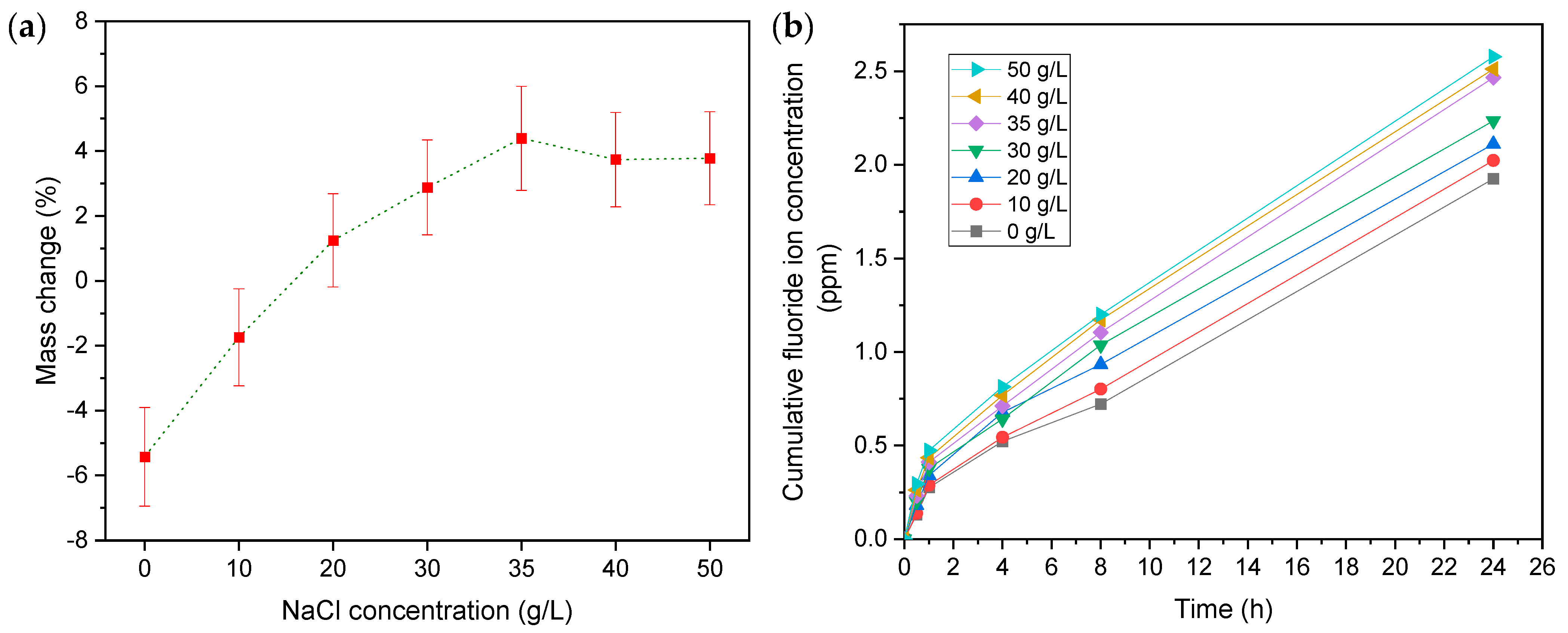
3.1.1. Mass Change and Fluoride Emissions

The mass change in the Nafion membrane and fluoride ion emission from the polymer chain is often associated with chemical degradation [17]. The mass of the membranes showed a decrease after 24 h of accelerated ex situ degradation in Fenton’s reagent with 0 and 10 g/L NaCl concentrations. At NaCl concentrations higher than 10 g/L, the mass of the membrane starts to increase as the concentration increases. However, the mass of the membrane starts gradually decreasing above 35 g/L NaCl concentrations with respect to the mass of the membranes treated with lower NaCl concentrations (Figure 1a). For the fluoride emissions, the cumulative fluoride concentration in the test solution continuously increases with time. The quantitative fluoride emission was found to be higher with higher NaCl concentrations (Figure 1b). Earlier studies on the ex situ accelerated degradation have reported only the loss in membrane mass with time at different test conditions mostly due to fluoride emissions [14,20,21]. In the comparable test conditions without NaCl, a 5% mass loss was observed, which is in agreement with our findings [17]. However, the increase in mass at higher NaCl concentrations, despite continuous fluoride emission, is peculiar. The three stages in the mass change trend are: (1) a decrease for 0 and 10 g/L NaCl, (2) an increase for 20, 30, and 35 g/L NaCl, and (3) a stabilizing trend at higher concentrations, which can be explained by the chemistry of the degradation test. The decrease in the mass of the membrane in the absence of NaCl is associated with fluoride loss. In the presence of NaCl, two mechanisms could take place. First, the substitution of Fe2+ in the exchanged membrane by Na+, owing to its higher reactivity, contributes to mass loss. Second, the replacement of hydrogen by Na+ in the hydroxyl group of degraded fragments of Nafion membranes contributes to mass increment. At a low NaCl concentration of 10 g/L, the first mechanism is dominant, leading to overall mass loss, and as the concentration increases, the second mechanism becomes dominant even to overcome the mass loss due to fluoride emission, resulting in membranes with increased mass. The trend towards stabilization at NaCl concentrations higher than 35 g/L suggests that the sodium ion content of the membrane reaches saturation. As a result, the replacement hydrogen ions in the membrane are no longer influenced by the concentration of NaCl.

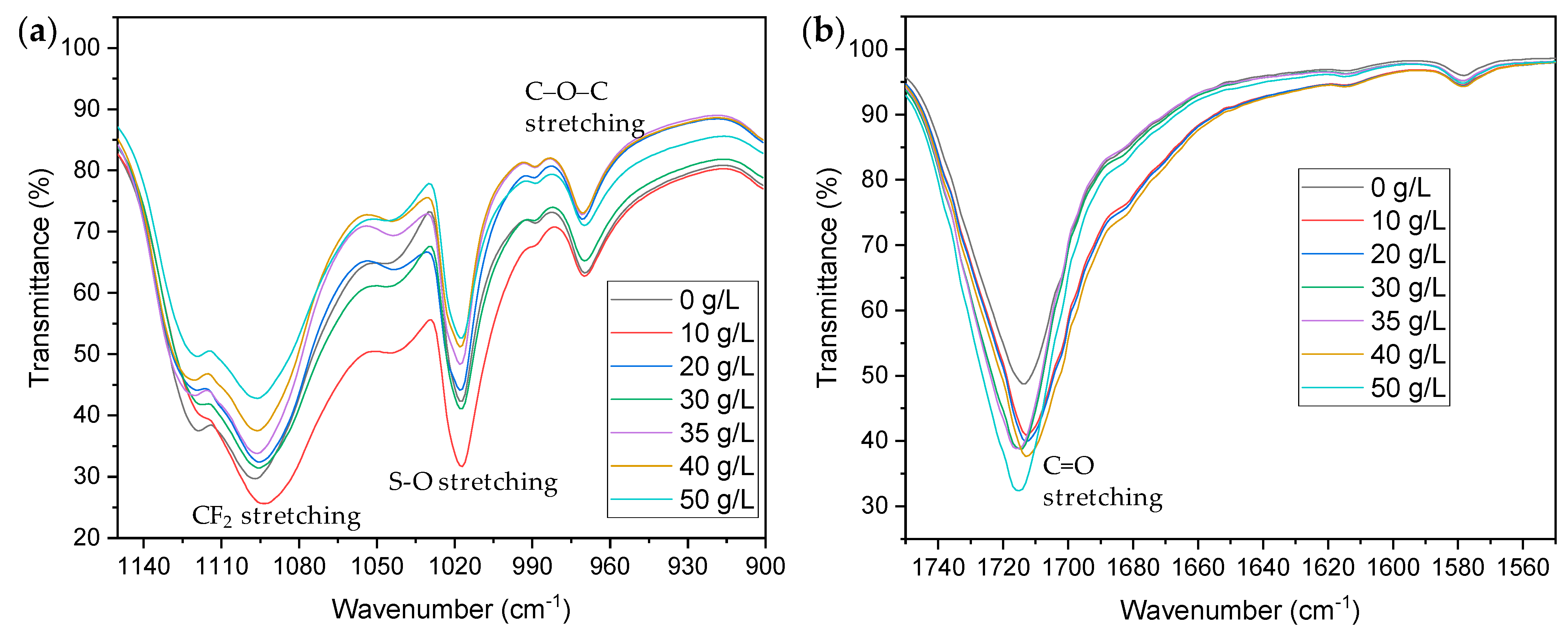
3.1.2. Changes in Chemical Properties

To investigate the effect of the NaCl concentration on the chemical structure of Nafion membranes, FTIR analysis was conducted. The FTIR spectra of Fenton’s tested Nafion membrane show peaks at ~1720, ~1100, ~1020, and ~970 cm−1 associated with C=O stretching, CF2 stretching, S–O stretching, and C–O–C stretching, respectively (Figure 2) [14,17]. Proton conduction is an essential property of PEM used in PEMFC, which is achieved by proton-hopping and diffusion mechanisms [22]. In the proton-hopping mechanism, a proton hops from one hydrolyzed site (−SO3H groups) to another site through the membrane, whereas in the diffusion mechanism, protonated water (H3O+) diffuses across the aqueous medium in response to the electrochemical difference. The change in the chemical structure of the membrane greatly affects both mechanisms, leading to deteriorated proton exchange, and hence a decline in the PEMFC performance. The FTIR peak associated with S–O stretching of sulfonic acid (SO3H) groups, which are mainly responsible for the proton conduction of the Nafion membrane, shows a declining trend with an increasing NaCl concentration (Figure 2a). The reduced transmittance peaks of the sulfonic group at higher NaCl concentrations suggest the deterioration of this group. Earlier studies have shown that transmittance peaks of the sulfonic group could be enhanced by crosslinking these groups using UV irradiation, resulting in improved proton hopping, and hence better proton conductivity of the membrane [22,23]. The location and width of the transmittance peak associated with the S–O stretching of the sulfonic acid (SO3H) group are sensitive to the presence and type of counteractions due to an induced polarization of S–O dipoles in the sulfonate group by the electrostatic field of the adjacent cation [24]. CF2 bonds located in the main chain are responsible for providing mechanical and thermal stability. The transmittance peak associated with CF2 stretching shows a declining trend. A similar decreasing trend can be seen in the transmittance peaks of C–O–C bonds (Figure 2a). The reduced transmittance peaks associated with CF2 and C–O–C bonds indicate the decline in the relative content of these bonds in the material, as suggested by the fluoride emission data [25]. Interestingly, the peaks associated with C=O at wavenumber ~1720 cm−1 show an increasing trend with increasing NaCl concentrations, indicating enhanced content of this functional group (Figure 2b). Previous studies have suggested that degradation of Nafion membranes could occur via main chain unzipping and side chain scission in the presence of hydroxyl radicals to generate C=O bonds [26].

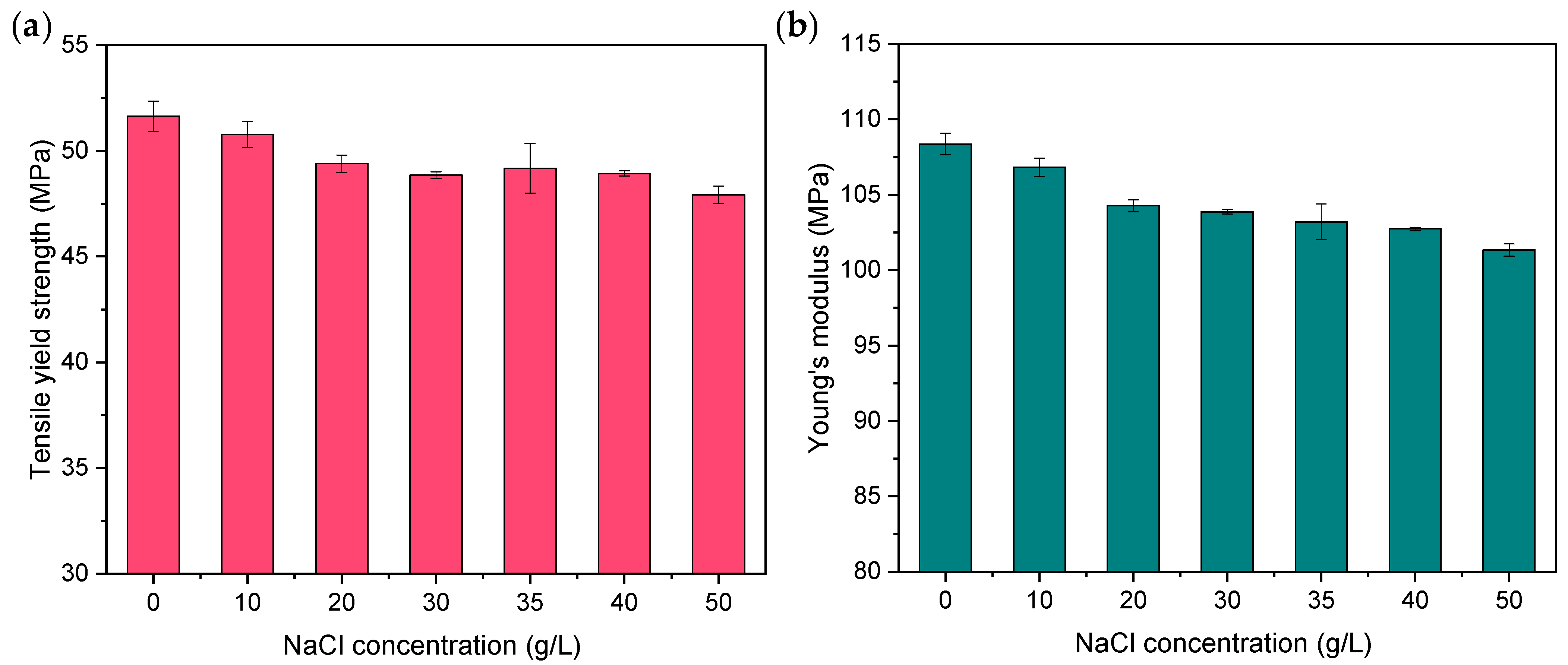
3.1.3. Changes in Mechanical Properties

The degradation of Nafion causes changes in both the morphology and structure of the membranes. Therefore, a decrease in the physical properties, especially the mechanical properties of the membrane, is expected [17,27]. Yield tensile strength is the maximum stress that can be applied to a ductile material before permanently deforming it. The yield strength of Nafion membranes that undergo Fenton’s test for 24 h decreases with increasing NaCl concentrations in the test solution (Figure 3a). Young’s modulus of a material is a fundamental property of the material that cannot be changed at a particular temperature and pressure unless the material degrades and density changes, which makes Young’s modulus an important parameter in studying material degradation. As the NaCl concentration increased from 0 to 50 g/L in the Fenton’s test solution, Young’s modulus of the membranes decreased by only about 6.5% in a 24 h accelerated degradation test (Figure 3b). The degradation of Nafion membranes is caused by the attack of hydroxyl radicals, which results in the unzipping of the main chain and scission of side chains, leading to fewer chain entanglements and a lower molecular weight of the polymer chains. This, in turn, can increase the mobility of the chains when mechanical loading is applied, and a lower Young’s modulus is observed. The amount of CF2 bonds in the main polymer chain decreases with increasing NaCl concentration, as shown in the fluoride emission data (Figure 1b) and FTIR spectra (Figure 2a), and C–O–C bonds’ breakage could be an explanation of why Young’s modulus decreases with increasing temperature and NaCl concentration. An earlier study indicated that the introduction of cations into the Nafion membranes by ion exchange could increase Young’s modulus of the membrane [28]. However, in our study, membranes underwent an accelerated degradation test after ion exchange. Thus, even though there could be a possibility of an increase in Young’s modulus due to cation exchange, the decrement caused by degradation is higher. Moreover, Young’s modulus of Nafion membranes is influenced by the ionic radius of the cation and increases with increasing ionic radius [29]. Sodium ions have a relatively small ionic radius among alkali metals, so the effect of introducing sodium ions into the Nafion membranes on Young’s modulus is not significant compared to that due to degradation caused by hydroxyl radicals.

3.2. Effect of Test Temperature

To investigate the effect of temperature, Fe2+-exchanged Nafion membranes were subjected to an ex situ accelerated degradation test in 30% H2O2 solutions with fixed NaCl concentrations of 35 g/L at temperatures 30, 40, 50, 60, 70, and 80 °C. Hydroxyl radicals are produced in Fenton’s test solution according to the reactions mentioned in Section 3.1. Changes in Nafion membranes in terms of their mass, chemical nature, and mechanical properties were monitored after 24 h of Fenton’s test at different temperatures. In addition, fluoride emissions in the test solution were measured at several time intervals.

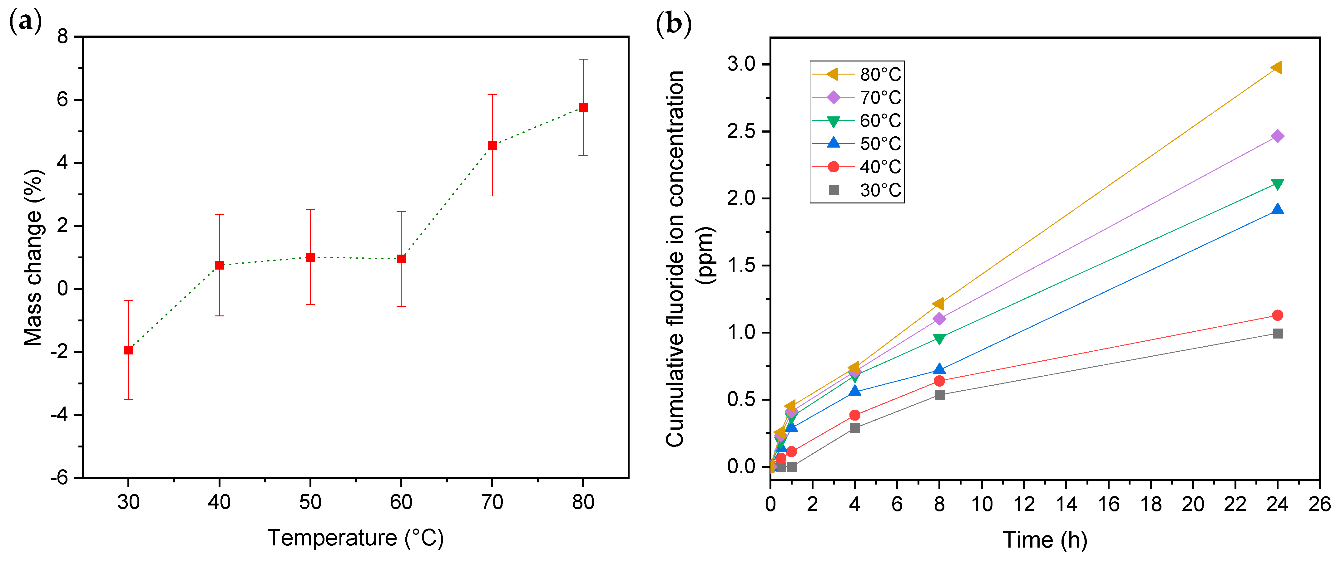
3.2.1. Mass Change and Fluoride Emissions

At a temperature of 30 °C and a NaCl concentration of 35 g/L, the membrane shows a decrease in mass after 24 h of degradation in Fenton’s test. However, with the increase in temperature, the mass of the membrane does not show a greater decrease; on the contrary, it shows an increasing trend (Figure 4a). The trend of mass change is similar to that with an increasing NaCl concentration (Section 3.1.1), though at a higher temperature, the mass change is more severe compared to a higher NaCl concentration. As discussed in Section 3.1.1, in the presence of NaCl, two mechanisms are associated with mass change of the membrane. First, the substitution of Fe2+ in the exchanged membrane by Na+ due to its higher reactivity contributes to mass loss. Second, the replacement of hydrogen by Na in the hydroxy group of degraded fragments of Nafion membranes contributes to a mass increment. At low temperatures, the first mechanism is dominant and, along with fluoride emission, results in the mass loss of the membrane. In contrast, at higher temperatures, the fluoride loss is severe (Figure 4b), and so is the degradation and formation of hydroxy-containing fragments. Consequently, as the temperature increases, the second mechanism becomes dominant, resulting in membranes with increased weight. Moreover, studies have shown that the increase in temperature can increase the interaction between the cations and the functional groups in the membrane while limiting their interaction with water molecules [3].
As for the fluoride emission, the cumulative fluoride concentration continuously increases with time at all temperatures, as was the case with different NaCl concentrations (Figure 4b). However, the extent of fluoride emission is much greater at higher temperatures. Several studies have highlighted that the emission rate of fluoride ions remains constant with reaction time [17,21,30], whereas some indicated that the concentration of fluoride ions in solution increases exponentially with reaction time and reaches saturation after 230 min and 120 min at 90 °C and 95 °C, respectively [31]. In our study, we found that the rate of fluoride emission is independent of the reaction time after the first hour of the degradation test. There could be several causes of differences in kinetics. We used H2O2 with stabilizers, which causes the hydroxyl radicals to be released slowly, unlike the one without the stabilizers, which reacts strongly. Some researchers have concluded that after a period of time, the solution is saturated with fluoride ions, and due to the absence of stabilizers, H2O2 is rapidly consumed. Kundu et al. [17] chose to change the H2O2 solution every 24 h when performing a 96 h Fenton’s test for the degradation of Nafion membranes and reported that the rate of release of fluoride ions did not change with the change in reaction time.

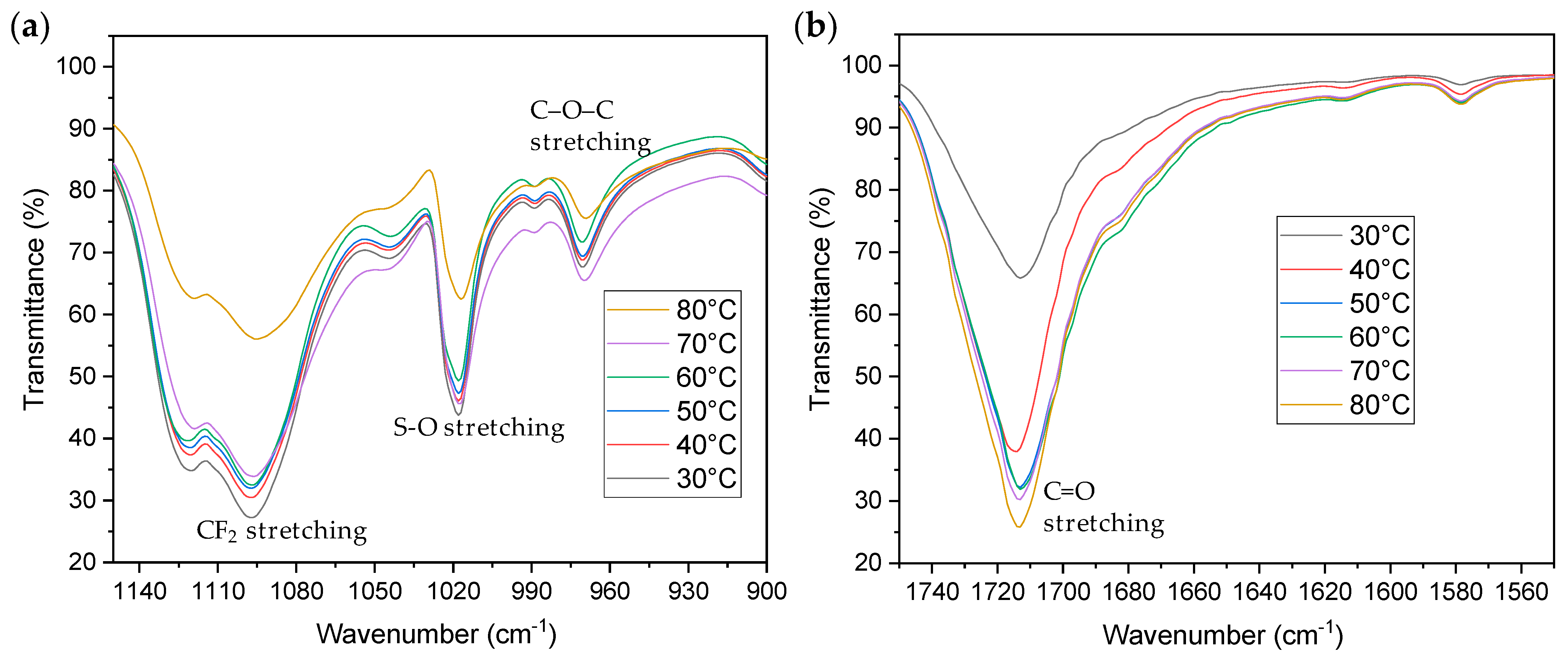
3.2.2. Changes in Chemical Properties

As mentioned in Section 3.1.2, proton conduction is an essential property of PEM used in PEMFC, which is achieved by proton-hopping and diffusion mechanisms [22]. It is believed that at low to medium temperatures (25–55 °C), proton hopping predominates, whereas diffusion mechanisms predominate at higher temperatures (85 °C). Therefore, the study of chemical changes in the membrane at different temperatures could provide insights into both the proton conduction and degradation behavior. The FTIR peak associated with S–O stretching of sulfonic acid (SO3H) groups shows a declining trend as the temperature of Fenton’s test increases (Figure 5a). The transmittance peak associated with CF2 stretching shows a declining trend with increasing temperature. A similar decreasing trend can be seen in the transmittance peaks of C–O–C bonds (Figure 5a). The peaks associated with C=O at wavenumber ~1720 cm−1 show an increasing trend with increasing temperature, indicating greater content of this functional group (Figure 5b). The reduced transmittance peaks associated with CF2 and C–O–C bonds and enhanced peaks associated with C=O indicate the chemical degradation of the membrane, as explained in Section 3.1.2.

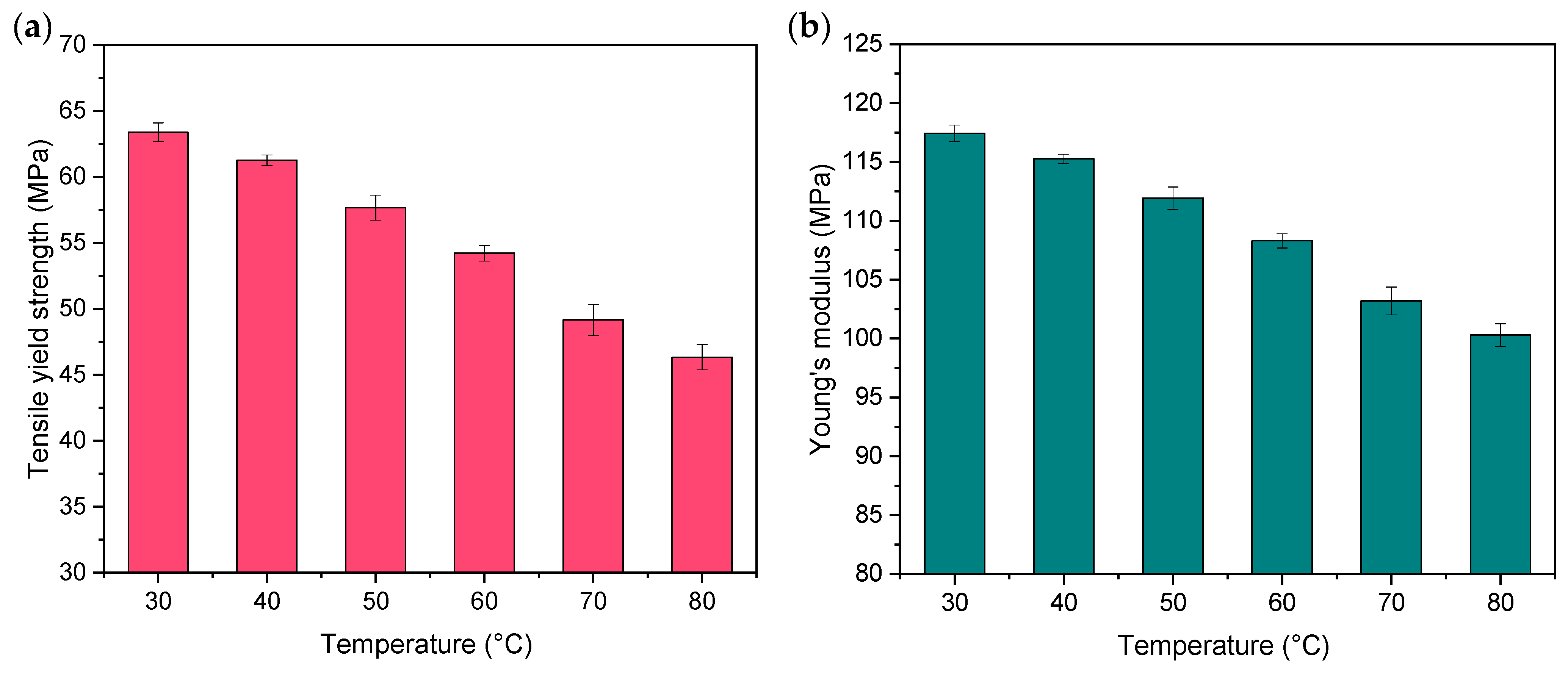
3.2.3. Changes in Mechanical Properties

The yield tensile strength of the Fenton-tested Nafion membranes decreases as the temperature of the accelerated degradation test increases (Figure 6a). The effect of NaCl concentrations on yield strength is the same as that on Young’s modulus, and it is the same case with temperature. The Young’s modulus of the membrane decreases with increasing temperature (Figure 6b), possibly due to both these mechanical properties being influenced by the physical crosslinking effect that occurs in the ionic clusters [17]. Based on our study, it could also be deduced that high temperature has more severe effects on mechanical properties and chemical degradation compared to high NaCl concentrations.

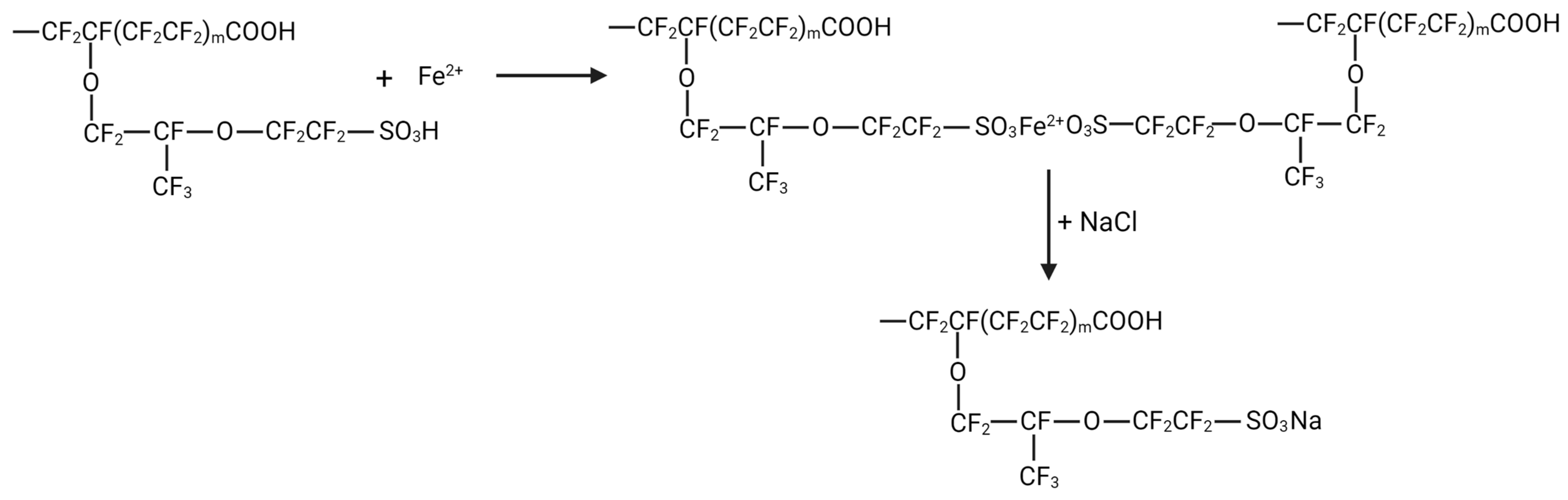
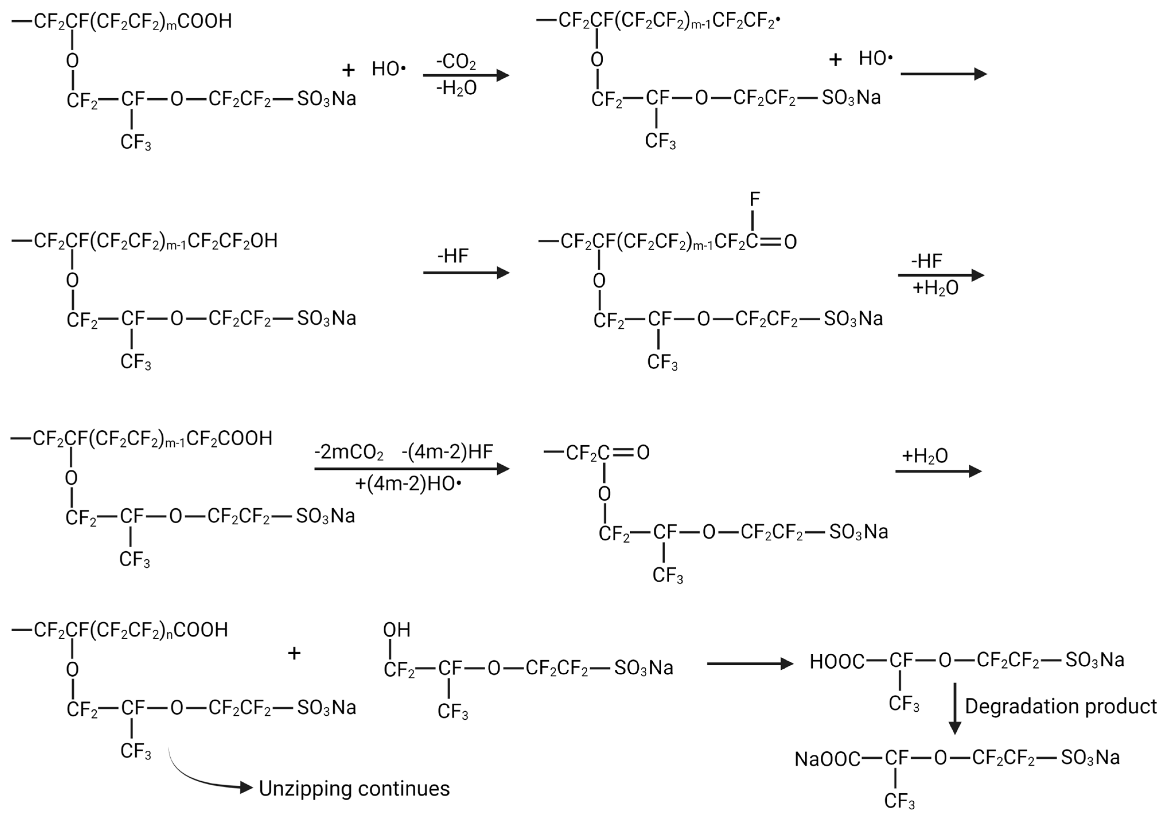
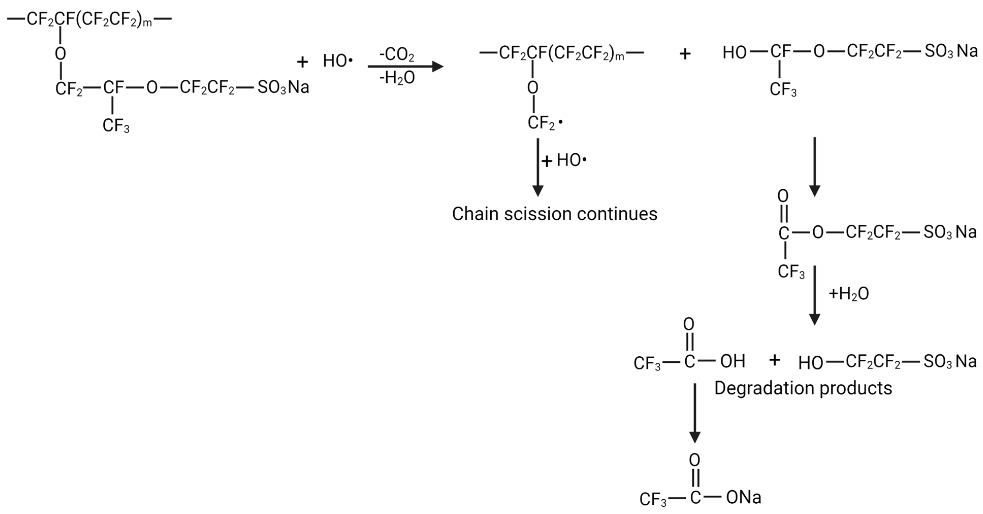
4. Mechanism of Degradation

Using all observations made in our study, the degradation mechanism of Nafion in the presence of NaCl can be proposed. In the first step, the Nafion membrane is ion-exchanged with Fe2+, which is replaced with Na+ during the Fenton test in the presence of NaCl (Figure 7). This was referred to as the first mechanism that causes mass loss among two mechanisms that are responsible for the mass change of Nafion membranes (Section 3.1.1).
There are mainly two ways of Nafion degradation caused by hydroxyl radicals: the main chain unzipping process and the side chain scission process. The main chain unzipping process starts from weak end groups such as –CF2COOH, –CF2H, and –CF=CF2 that are generated during the polymer manufacturing process [20]. After initial contact with a hydroxyl radical, a COOH group is formed, from which the main chain unzipping starts (Figure 8) [27]. The process is initiated by the extraction of carboxylic hydrogen by HO•, followed by the fragmentation of the intermediate radical species to produce a fluoro-radical [32]. The other products of this degradation process of Nafion are CO2, HF, and a carboxylic group containing fragments. The H in the carboxylic group is replaced by Na+, and this process causes the increment in the mass of the membrane, which is referred to as the second mechanism responsible for the mass change of the Nafion membrane in the presence of NaCl (Section 3.1.1). HF is produced by CF2 bond breakage, and therefore, the intensity of FTIR transmittance peaks associated with the CF2 bond decreases. Similarly, the intensity of FTIR transmittance peaks associated with C=O increases because of the carboxylic group containing degraded fragments.
In the side chain scission process, the carbon-oxygen-carbon (C–O–C) group decomposes. If a suitably stable radical can be produced, a variety of radical substitution reactions for the breakdown of the C–O–C group may be conceivable. At the increased free radical concentration, the C–O–C group is attacked and most likely generates a fragmented fluoro-radical. The other product of this decomposition finally produces a carboxylic group containing fragments (Figure 9). As in the first process, H in the carboxylic group could be replaced by Na+, and this process causes an increment in the mass of the membrane. This process of Nafion degradation is more complex, since the reaction is moderate and only noticeable after long-term operation. Moreover, the side chain scission process can be initialized during extremely dry conditions, although the degradation can be propagated through the unzipping process during moderately wet conditions [26]. According to our FTIR spectra observations (decrement in the intensity of peaks associated with CF2 and C–O–C), both processes of degradation are likely to occur in our experiments. Given the FTIR spectra show a decrement in the intensity of transmittance peaks of S–O groups, a radical attack on sulfonic acid moiety is expected.

5. Conclusions

We investigated the effects of NaCl concentration and temperature on the degradation of Nafion membrane by ex situ accelerated degradation using Fenton’s reagents. We found that the mass of the membrane does not consistently decrease with different NaCl concentrations, as it does in Fenton’s test in the absence of NaCl. The mass of Fenton’s tested membranes increases in the case of a high NaCl concentration and high temperature. Mass changes of the membrane are associated with the H ion replacement by Na+ in the carboxylic group containing degraded fragments. The cumulative fluoride ion concentration in the test solution continually increases with time with an increasing NaCl concentration and temperature at a constant rate of emission from the membrane with time. The FTIR spectra revealed that the intensity of peaks associated with CF2, C–O–C, and S–O decreased as the NaCl concentration and the temperature increased. The decrement in peaks associated with these bonds suggests the radical attack via main chain unzipping, side chain scission, and attack on the sulfonic acid moiety. The intensity of the FTIR peak associated with C=O increases with increasing NaCl concentration and temperature, indicating increased degradation. The yield tensile strength and Young’s modulus of Nafion membranes both decrease with increasing temperature and NaCl concentration, which is attributed to the degradation of the Nafion membranes resulting in the detachment of side chains, causing a decrease in the molecular weight of the polymer and a reduction in entanglement. Comparatively, increasing temperatures showed a more severe effect on the degradation of the membrane than increasing NaCl concentrations. Nevertheless, the presence of NaCl accelerates the degradation of Nafion, and for the advantageous applications of PEMFCs in marine transportation, membrane systems that are more resistant to salty conditions could be envisioned.

Author Contributions

Conceptualization, methodology, visualization, D.M., C.S., and V.V.; validation, formal analysis, investigation, D.M. and C.S.; resources, V.V.; writing—original draft preparation, D.M.; writing—review and editing, D.M., C.S., J.M., F.B., and V.V.; supervision, F.B. and V.V.; project administration, V.V.; funding acquisition, D.M. and V.V. All authors have read and agreed to the published version of the manuscript.

Funding

This research was supported by KU Leuven Internal Funds Bijzonder Onderzoeksfonds 2020 (grant number STG/20/013), a KU Leuven Internal Funds Bijzonder Onderzoeksfonds FLOF PhD mandate, and a Fonds Wetenschappelijk Onderzoek—Vlaanderen (FWO) strategic basic research fellowship (1S13922N).

Data Availability Statement

The raw data are available on request from the corresponding author.

Acknowledgments

D.M. acknowledges support from a Fonds Wetenschappelijk Onderzoek—Vlaanderen (FWO) strategic basic research fellowship (1S13922N).

Conflicts of Interest

The authors declare no conflict of interest. The funders had no role in the design of the study; in the collection, analyses, or interpretation of data; in the writing of the manuscript; or in the decision to publish the results.

References

  1. Rivarolo, M.; Rattazzi, D.; Lamberti, T.; Magistri, L. Clean Energy Production by PEM Fuel Cells on Tourist Ships: A Time-Dependent Analysis. Int. J. Hydrog. Energy 2020, 45, 25747–25757. [Google Scholar] [CrossRef]
  2. Psaraftis, H.N.; Kontovas, C.A. Decarbonization of Maritime Transport: Is There Light at the End of the Tunnel? Sustainability 2021, 13, 237. [Google Scholar] [CrossRef]
  3. Zhang, G.; Yang, G.; Li, S.; Shen, Q.; Jiang, Z.; Li, Z.; Wang, H.; Liao, J.; Zhang, H. Molecular Dynamics Study on the Impacts of Cations in Sea Salt Aerosol on Transport Performance of Nafion Membranes for PEMFCs in Marine Application. Int. J. Hydrog. Energy 2022, 47, 27139–27149. [Google Scholar] [CrossRef]
  4. Marine Application of a New Fuel Cell Powertrain Validated in Demanding Arctic Conditions. Available online: https://projectsites.vtt.fi/sites/maranda/ (accessed on 6 January 2023).
  5. Elkafas, A.G.; Rivarolo, M.; Gadducci, E.; Magistri, L.; Massardo, A.F. Fuel Cell Systems for Maritime: A Review of Research Development, Commercial Products, Applications, and Perspectives. Processes 2023, 11, 97. [Google Scholar] [CrossRef]
  6. First Fuel Cell Passenger Ship Unveiled in Hamburg. Fuel Cells Bull. 2008, 2008, 4–5. [CrossRef]
  7. Zhu, J.; Tan, J.; Pan, Q.; Liu, Z.; Hou, Q. Effects of Mg2+ Contamination on the Performance of Proton Exchange Membrane Fuel Cell. Energy 2019, 189, 116135. [Google Scholar] [CrossRef]
  8. Qi, J.; Wang, X.; Ozdemir, M.O.; Uddin, M.A.; Bonville, L.; Pasaogullari, U.; Molter, T. Effect of Cationic Contaminants on Polymer Electrolyte Fuel Cell Performance. J. Power Sources 2015, 286, 18–24. [Google Scholar] [CrossRef] [Green Version]
  9. Wang, X.; Qi, J.; Ozdemir, O.; Uddin, A.; Pasaogullari, U.; Bonville, L.J.; Molter, T. Ca2+ as an Air Impurity in Polymer Electrolyte Membrane Fuel Cells. J. Electrochem. Soc. 2014, 161, F1006. [Google Scholar] [CrossRef]
  10. Zhang, G.; Yang, G.; Shen, Q.; Li, S.; Li, Z.; Liao, J.; Jiang, Z.; Wang, H.; Zhang, H.; Ye, W. Study on the Transport Performance Degradation of Nafion Membrane Due to the Presence of Na+ and Ca2+ Using Molecular Dynamics Simulations. J. Power Sources 2022, 542, 231740. [Google Scholar] [CrossRef]
  11. Hongsirikarn, K.; Goodwin, J.G.; Greenway, S.; Creager, S. Effect of Cations (Na+, Ca2+, Fe3+) on the Conductivity of a Nafion Membrane. J. Power Sources 2010, 195, 7213–7220. [Google Scholar] [CrossRef]
  12. Sasank, B.V.; Rajalakshmi, N.; Dhathathreyan, K.S. Performance Analysis of Polymer Electrolyte Membrane (PEM) Fuel Cell Stack Operated under Marine Environmental Conditions. J. Mar. Sci. Technol. 2016, 21, 471–478. [Google Scholar] [CrossRef]
  13. Mikkola, M.S.; Rockward, T.; Uribe, F.A.; Pivovar, B.S. The Effect of NaCl in the Cathode Air Stream on PEMFC Performance. Fuel Cells 2007, 7, 153–158. [Google Scholar] [CrossRef]
  14. Kinumoto, T.; Inaba, M.; Nakayama, Y.; Ogata, K.; Umebayashi, R.; Tasaka, A.; Iriyama, Y.; Abe, T.; Ogumi, Z. Durability of Perfluorinated Ionomer Membrane against Hydrogen Peroxide. J. Power Sources 2006, 158, 1222–1228. [Google Scholar] [CrossRef]
  15. Passalacqua, E.; Pedicini, R.; Carbone, A.; Gatto, I.; Matera, F.; Patti, A.; Saccà, A. Effects of the Chemical Treatment on the Physical-Chemical and Electrochemical Properties of the Commercial NafionTM NR212 Membrane. Materials 2020, 13, 5254. [Google Scholar] [CrossRef]
  16. Iriarte, D.; Andrada, H.; Maldonado Ochoa, S.A.; Silva, O.F.; Vaca Chávez, F.; Carreras, A. Effect of Acid Treatment on the Physico-Chemical Properties of Nafion 117 Membrane. Int. J. Hydrog. Energy 2022, 47, 21253–21260. [Google Scholar] [CrossRef]
  17. Kundu, S.; Simon, L.C.; Fowler, M.W. Comparison of Two Accelerated NafionTM Degradation Experiments. Polym. Degrad. Stab. 2008, 93, 214–224. [Google Scholar] [CrossRef]
  18. Millero, F.J.; Feistel, R.; Wright, D.G.; McDougall, T.J. The Composition of Standard Seawater and the Definition of the Reference-Composition Salinity Scale. Deep Sea Res. Part Oceanogr. Res. Pap. 2008, 55, 50–72. [Google Scholar] [CrossRef]
  19. Danilczuk, M.; Bosnjakovic, A.; Kadirov, M.K.; Schlick, S. Direct ESR and Spin Trapping Methods for the Detection and Identification of Radical Fragments in Nafion Membranes and Model Compounds Exposed to Oxygen Radicals. J. Power Sources 2007, 172, 78–82. [Google Scholar] [CrossRef]
  20. Carlsson, A.H.; Joerissen, L. Accelerated Degradation of Perfluorinated Sulfonic Acid Membranes. ECS Trans. 2009, 25, 725–732. [Google Scholar] [CrossRef]
  21. Robert, M.; El Kaddouri, A.; Perrin, J.-C.; Raya, J.; Lottin, O. Time-Resolved Monitoring of Composite NafionTM XL Membrane Degradation Induced by Fenton’s Reaction. J. Membr. Sci. 2021, 621, 118977. [Google Scholar] [CrossRef]
  22. Rao, A.S.; Rashmi, K.R.; Manjunatha, D.V.; Jayarama, A.; Pinto, R. Role of UV Irradiation of Nafion Membranes on Ionic Groups Responsible for Proton Conduction and Mechanical Strength: A FTIR Spectroscopic Analysis. Mater. Today Commun. 2020, 25, 101471. [Google Scholar] [CrossRef]
  23. Rao, A.S.; Rashmi, K.R.; Manjunatha, D.V.; Jayarama, A.; Prabhu, S.; Pinto, R. Pore Size Tuning of Nafion Membranes by UV Irradiation for Enhanced Proton Conductivity for Fuel Cell Applications. Int. J. Hydrog. Energy 2019, 44, 23762–23774. [Google Scholar] [CrossRef]
  24. Mauritz, K.A.; Moore, R.B. State of Understanding of Nafion. Chem. Rev. 2004, 104, 4535–4586. [Google Scholar] [CrossRef]
  25. Griffiths, P.R.; De Haseth, J.A. Chemical analysis. In Fourier Transform Infrared Spectrometry, 2nd ed.; Wiley-Interscience: Hoboken, NJ, USA, 2007; ISBN 978-0-471-19404-0. [Google Scholar]
  26. Okonkwo, P.C.; Ben Belgacem, I.; Emori, W.; Uzoma, P.C. Nafion Degradation Mechanisms in Proton Exchange Membrane Fuel Cell (PEMFC) System: A Review. Int. J. Hydrog. Energy 2021, 46, 27956–27973. [Google Scholar] [CrossRef]
  27. Chen, C.; Fuller, T.F. The Effect of Humidity on the Degradation of Nafion® Membrane. Polym. Degrad. Stab. 2009, 94, 1436–1447. [Google Scholar] [CrossRef]
  28. Kawano, Y.; Wang, Y.; Palmer, R.A.; Aubuchon, S.R. Stress-Strain Curves of Nafion Membranes in Acid and Salt Forms. Polímeros 2002, 12, 96–101. [Google Scholar] [CrossRef] [Green Version]
  29. Kundu, S.; Simon, L.C.; Fowler, M.; Grot, S. Mechanical Properties of NafionTM Electrolyte Membranes under Hydrated Conditions. Polymer 2005, 46, 11707–11715. [Google Scholar] [CrossRef]
  30. Curtin, D.E.; Lousenberg, R.D.; Henry, T.J.; Tangeman, P.C.; Tisack, M.E. Advanced Materials for Improved PEMFC Performance and Life. J. Power Sources 2004, 131, 41–48. [Google Scholar] [CrossRef]
  31. Sugawara, T.; Kawashima, N.; Murakami, T.N. Kinetic Study of Nafion Degradation by Fenton Reaction. J. Power Sources 2011, 196, 2615–2620. [Google Scholar] [CrossRef]
  32. Frühwirt, P.; Kregar, A.; Törring, J.T.; Katrašnik, T.; Gescheidt, G. Holistic Approach to Chemical Degradation of Nafion Membranes in Fuel Cells: Modelling and Predictions. Phys. Chem. Chem. Phys. 2020, 22, 5647–5666. [Google Scholar] [CrossRef]
Figure 1. The effects of NaCl concentrations on the degradation behavior of Nafion: (a) mass change (%) with respect to the initial mass of the Nafion membrane after 24 h ex situ Fenton’s test with different NaCl concentrations; (b) cumulative fluoride concentration (ppm) in the Fenton’s test solution with time.
Energies 16 02256 g001
Figure 2. FTIR spectra of Nafion membranes after ex situ accelerated degradation in the presence of different NaCl concentrations: (a) for wavenumber ranging from 900–1150 cm−1; (b) for wavenumber ranging from 1550–1750 cm−1.
Energies 16 02256 g002
Figure 3. Mechanical properties of the membrane after ex situ degradation test with Fenton’s reagent: (a) tensile yield strength (MPa) of membranes tested in the presence of different NaCl concentrations; (b) Young’s modulus (MPa) of membranes tested in the presence of different NaCl concentrations.
Energies 16 02256 g003
Figure 4. The effects of temperature on the degradation behavior of Nafion: (a) mass change (%) with respect to the initial mass of the Nafion membrane after 24 h ex situ Fenton’s test at different temperatures; (b) cumulative fluoride concentration (ppm) in the Fenton’s test solution with time; the horizontal axis of the graph is not linear.
Energies 16 02256 g004
Figure 5. FTIR spectra of Nafion membranes after ex situ accelerated degradation at different temperatures: (a) for wavenumber ranging from 900–1150 cm−1; (b) for wavenumber ranging from 1550–1750 cm−1.
Energies 16 02256 g005
Figure 6. Mechanical properties of the membrane after ex situ degradation test with Fenton’s reagent: (a) tensile yield strength (MPa) of membranes at different temperatures; (b) Young’s modulus (MPa) of membranes tested at different temperatures.
Energies 16 02256 g006
Figure 7. The schematic mechanism of ion exchange of Nafion membrane with Fe2+ followed by replacement of Fe2+ with 2 Na+ during Fenton’s test in the presence of NaCl.
Energies 16 02256 g007
Figure 8. Schematic of the main chain unzipping process.
Energies 16 02256 g008
Figure 9. Schematic of the side chain scission process.
Energies 16 02256 g009
Disclaimer/Publisher’s Note: The statements, opinions and data contained in all publications are solely those of the individual author(s) and contributor(s) and not of MDPI and/or the editor(s). MDPI and/or the editor(s) disclaim responsibility for any injury to people or property resulting from any ideas, methods, instructions or products referred to in the content.

