Article

On the Hydrothermal Behavior of Fluid Flow and Heat Transfer in a Helical Double-Tube Heat Exchanger with Curved Swirl Generator; Impacts of Length and Position

by
Seyed Soheil Mousavi Ajarostaghi
1,2,*,
Seyed Hossein Hashemi Karouei
2,
Mehdi Alinia-kolaei
3,
Alireza Ahmadnejad Karimi
4,
Morteza Mohammad Zadeh
5 and
Kurosh Sedighi
2
1
Mechanical Engineering Department, Université de Sherbrooke, Sherbrooke, QC J1K 2R1, Canada
2
Department of Mechanical Engineering, Babol Noshirvani University of Technology (BNUT), P.O. Box 484, Babol 47148-71167, Iran
3
Department of Mechanical Engineering, Shahid Rajaee Teacher Training University, P.O. Box 136-16785, Tehran 16788-15811, Iran
4
Department of Mechanical Engineering, Mazandaran Institute of Technology (MIT), P.O. Box 744, Babol 47481-61136, Iran
5
Department of Mechanical Engineering, Mazandaran University of Science and Technology (MUST), P.O. Box 734, Babol 47166-85635, Iran
*
Author to whom correspondence should be addressed.
Energies 2023, 16(4), 1801; https://doi.org/10.3390/en16041801
Submission received: 29 December 2022 / Revised: 30 January 2023 / Accepted: 8 February 2023 / Published: 11 February 2023

Abstract

:
The hydrothermal behavior in a helical double-tube heat exchanger is numerically estimated. A new type of swirl generator with two sections, including; outer curved blades and a semi-conical section with two holes in the inner section, is employed. Two geometrical factors, containing the length (L1) and the position of the swirl generator (S), are used for investigation. The calculations were performed by a commercial FVM code, ANSYS FLUENT 18.2. The numerical outcomes show that a shorter length of the swirl generator leads to a better hydrothermal behavior. Accordingly, the model with L1 = 100 mm at m ˙ = 0.008 kg/s achieves the maximum thermal performance by about 17.65, 53.85, and 100% enhancement compared to the models L1 = 200, 300 mm, and without swirl generator. Among the different studied positions of the swirl generator, the maximum heat transfer coefficient and average Nusselt number in entire mass flow rates belong to the case with position S = 0.3π mm. Moreover, the thermal performance of the case with S = 0.3π mm is higher than cases with S = 0.1π mm, S = 0.5π mm, and without swirl generator by about 11.11, 53.84, and 100%, respectively.

1. Introduction

Heat exchangers are a crucial section of numerous industries, from pharmaceuticals to petrochemicals. Today, systems based on renewable energies are considered one of the main sources of power production in the world [1,2,3]. Heat exchangers figure prominently in the performance of these systems. Moreover, in renewable systems, there is a considerable amount of waste heat, which can be recovered by using suitable heat exchangers [4]. This wide application requires some researchs to augment the heat transfer amount. Overall, there are two kinds of heat exchangers, including; passive and active types [5], which use an external force. Unlike the active type, the passive type does not consume external work [6]. Therefore, the passive type has received more attention from researchers and industrialists. In the passive model, various methods are used to create secondary and rotational flows within the fluid flow, which brings greater turbulence of the fluid and thus augments the heat transfer rate. These methods consist of using nanofluids [7,8,9,10], spiral tubes [11,12], extended surfaces (fins) [13,14,15,16], swirl generators [17,18], and corrugated walls [19,20].
Another advantage of heat exchangers is that the employed working fluid can be two-phase, which is one of the practical features of this type of equipment. Therefore, they can be utilized at different points of power and refrigeration cycles [21,22,23].
Tang et al. [24] empirically scrutinized the heat exchange rate in finned tube heat exchangers considering different types of fins. The empirical outcomes exhibited that the hydrothermal behavior increases with increasing fin length. Wongcharee et al. [25] investigated the heat exchange in a corrugated tube, and the outcomes demonstrated that the heat exchange amount rises with the reduction of the swirl ratio. Darzi et al. [26] performed an empirical heat transfer analysis of nanofluid flow in a corrugated pipe. They recognized that the combination of nanofluid and corrugated surfaces causes an augmented heat transfer rate of up to 330 percent. Du et al. [27] numerically examined the hydrothermal behavior of a heat exchanger with helical baffles and elliptical tubes. They demonstrated that the overall efficiency of the improved heat exchanger can be increased by up to 50 percent. Bahiraei et al. [28] evaluated the heat transfer in a triple-pipe heat exchanger in the presence of fins as swirl generators. They found that the thermal performance increases as the height of the fins rises. Moreover, the lower the pitch, the higher the thermal performance. Abolarin et al. [29] estimated the changes in heat transfer in a pipe using twisted tape as a vortex producer. They analyzed the impacts of geometrical factors on thermal properties. The outcomes revealed that the joint angle occupies a prominent place in the heat transfer changes. They also found that the temperatures near the walls increase when the wavelength is smaller. Zhang et al. [30] studied the hydrothermal behavior in corrugated pipes. Based on the obtained outcomes, employing the corrugated pipe enhanced the heat transfer amount.
Kareem et al. [31] evaluated the hydrothermal behavior in a helically corrugated pipe by empirical and numerical analysis. The outcomes indicated that the greater the severity of the tube, the upper the thermal performance. Lu et al. [32] numerically examined the thermal performance of a pipe with a swirl generator. They found that better hydrothermal behavior can be achieved by using a swirl generator with a smaller distance between the leading edge and the holes of the swirl generator. In their experiments, Mashoofi et al. [33] deliberated the thermal behavior of fluid flow in a pipe with a coil as a vortex producer. The average Nusselt number could be increased up to 32 percent in the provided thermal system. Noorbakhsh et al. [34] utilized twisted tapes with the same twist angle on both sides (hot and cold) of a double-pipe heat exchanger to raise the heat transfer amount and numerically investigated the heat transfer characteristics of the proposed thermal system. The twisted tapes used acted as extended surfaces (fins) and as swirl generators. Their numerical outcomes exhibited that the more fins (or twisted tapes) used, the higher the average Nusselt number. Kwon et al. [35] numerically considered the change in thermal efficiency when a static mixer is used in a pipe to improve the heat transfer amount. Their numerical outcomes displayed that the heat transfer coefficient augments up to 100 percent by using the proposed static mixer. For a more detailed review of turbulators with various geometries, it is better to refer to review articles [36].
Hashemi Karouei and Mousavi Ajarostaghi [37] examined numerically the hydrothermal behavior inside a double tube heat exchanger with a helical vortex generator (VG). The used VG in their work is similar to the employed one in the present work. In their work, the impacts of the radius of the VGs holes and the inner radius of the VG on the thermal performance of the heat exchanger were examined. Their numerical outcomes depicted that as the t VGs inner radius augments, the thermal performance increases by about 80 percent. Moreover, augmentation of the radius of VGs hole by about 133.34 percent causes an increase in the thermal performance by about 50 percent. In the other work by this group [38], they employed hybrid nanofluids instead of water in the inner channel of the heat exchanger. The employed working fluids were water-silver-graphene and water-iron oxide-multi wall carbon nanotubes. Their outcomes illustrated that among the evaluated working fluids, silver-graphene/water was the finest one considering thermal performance. Hashemi Karouei et al. [39] worked on a heat exchanger, the same as the employed one in the present work, in the other work in which the impacts of the angle and number of VGs blades on the thermal performance were examined by performing numerical simulations. Their results depicted that the best case belongs to the model with twelve numbers of blades considering thermal performance. Furthermore, considering various angles of VGs blades, a model with a blade angle of 180 degrees was the finest one in terms of thermal performance.
Here, a new type of swirl generator containing some blades and a semi-conical sector is developed to improve the heat transfer percentage in a helical double tube heat exchanger. The proposed swirl generator is curved with some vanes to produce the vortex streams. Furthermore, two holes in the semi-conical sector of the swirl generator are considered to cause more disturbance to the flow. The position and length of the suggested swirl generator are the evaluated geometrical factors here. It should be noted that these two geometrical parameters were not investigated and analyzed in previous works [37,38,39]. The impacts of the geometrical and practical factors are investigated by performing finite-volume method-based (FVM) simulations.

2. Materials and Methods

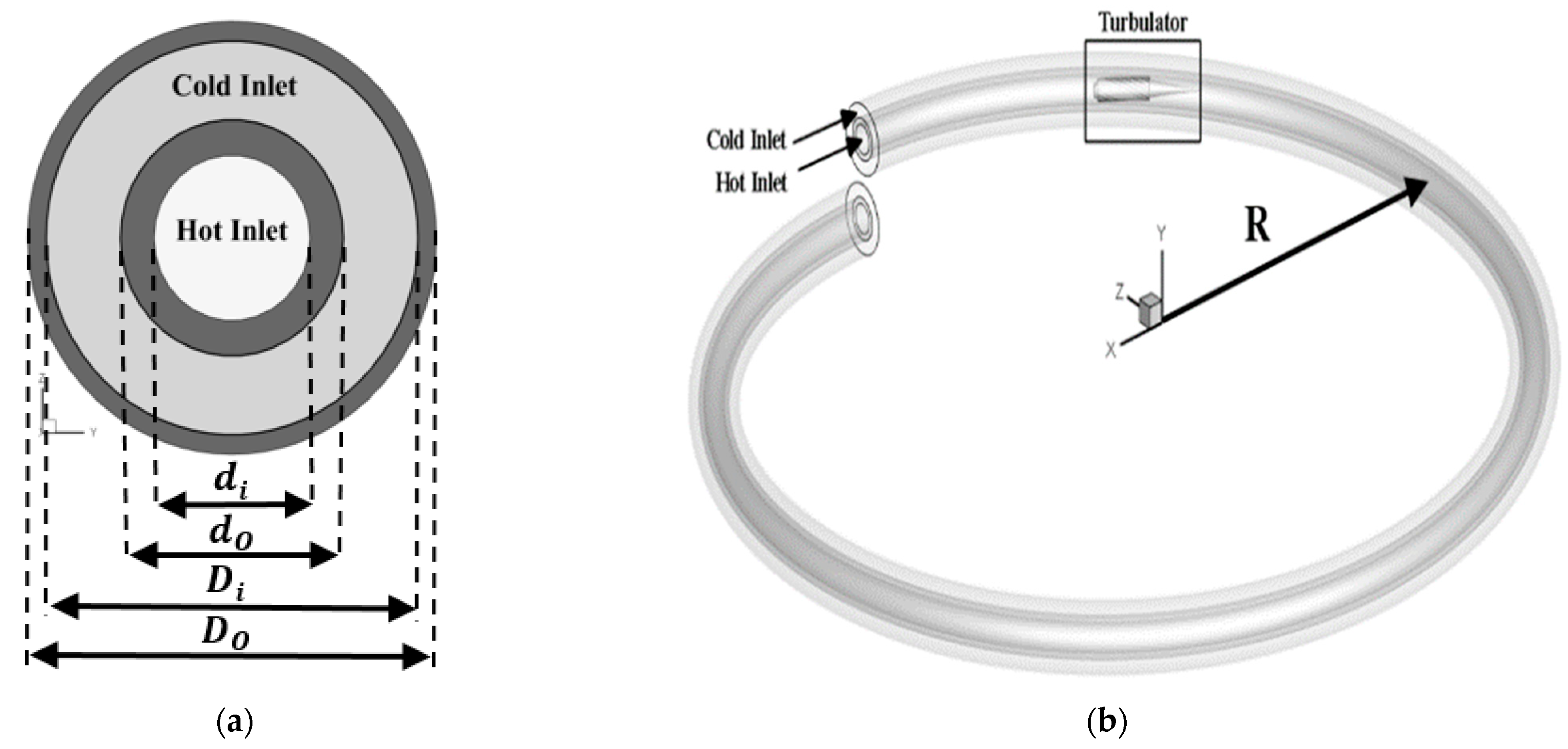
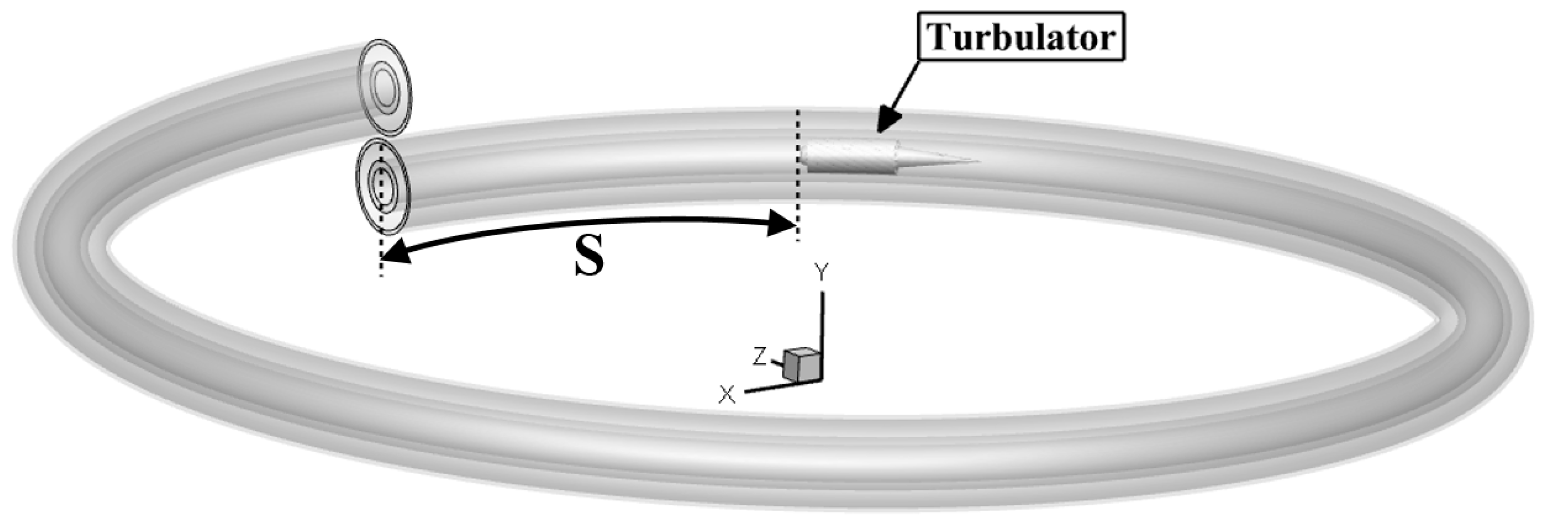
2.1. Problem Description

The schematic diagram of the considered helical double-tube heat exchanger in different views is shown in Figure 1. Moreover, the 3D views of the employed curved swirl generator and 2D-view of the swirl generator’s cross-section with geometric factors are illustrated in Figure 2. The proposed heat exchanger is rounded with a radius of 2π radians. A novel swirl generator is used inside the inner tube at a distance of 0.1 radians from the inlet of the inner tube. The used swirl generator consists of two parts, (i) the vanes and (ii) a semi-conical part. The lengths of these parts are L1 and L2, respectively. The length L2 is kept constant by 100 mm. Water is considered here as the working fluid on both sides of the heat exchanger. The geometrical factor values are given in Table 1. In addition, the thermophysical characteristics of water and steel (material of the employed swirl generator) are given in Table 2.
The present study consists of two sectors. First, the influence of the length of the used curved swirl generator on the hydrothermal behavior of the suggested heat exchanger is numerically investigated. The schemes of the swirl generators with various lengths (L1) studied here are shown in Figure 3. The following three lengths are investigated: 100, 200, and 300 mm. The position of the applied curved swirl generator is kept constant here with S = 0.1π mm.
In the next section, the impact of the position of the applied curved swirl generator in the inner spiral tube on the thermal manner of the heat exchanger is investigated by numerical simulations. The schematics of the swirl generators with different positions (S) evaluated here are shown in Figure 4. Three different positions of the used swirl generator with S = 0.1π, 0.3π, and 0.5π mm are investigated. In this part, the length of the swirl generator is kept constant with L1 = 100 mm.

2.2. Governing Equations

The conservation equations of mass, momentum, and energy are the following [40]:
ρ t + . ( ρ v ) = 0
( ρ v ) t + . ( ρ v v ) = p + . ( μ v )
( ρ c p T ) t + . ( v ( ρ c p T ) ) = ( k T )
The employed dimensionless parameters are as follows [37,38,39]:
N u a v e = h m d h k
f = 2 d h Δ p ρ u 2 L
η = ( N u N u 0 ) ( f 0 f ) 1 3
where Nuave, f, and η are average Nusselt number, friction factor, and thermal performance, respectively.
In the present work, the Schmidt correlation [41] has been employed to calculate the critical Reynolds number in a helical tube as follows:
R e C r = 2300 [ 1 + 8.6 ( r R C ) 0.45 ]
In Equation (7), RC and r are the helical radius and inner coil radius, respectively. This equation is confirmed for the condition of (1/860) < (r/RC). In the present work (the case without turbulator), the value of critical Reynolds number according to the Schmidt correlation is 6154.
Moreover, there is another correlation that has been exhibited by Ito [42] as follows:
R e C r = 20000 ( r R C ) 0.32
Equation (8) is confirmed for the condition of (1/860) < (r/RC) < (1/15). In the present work (the case without turbulator), the value of critical Reynolds number according to the Ito correlation is 6240. In the study, the greatest value of considered Reynolds number is ReMax = 1700, which is 3.63 and 3.67 times more than the critical Reynolds number according to the correlations of Schmidt and Ito, respectively. So, the fluid flow regime in this work has been considered laminar.
Moreover, in a number of previously published articles, while the critical Reynolds number in a simple pipe is calculable by placing a swirl generator (insert or turbulator) in a simple pipe, the researchers still considered the laminar flow regime in the range of the Reynolds number lower than the ReCr in a plain pipe. Lim et al. [43] analyzed the hydrothermal behavior in a tube equipped with twisted tape by performing empirical tests and numerical simulations. The highest evaluated Reynolds number in their work was Re = 1400, which is 1/1.6 times the critical Reynolds number of a plain pipe. They illustrated that the fluid flow is laminar in this Reynolds number considering a tube with twisted tape. Moreover, Zheng et al. [44] examined the thermal process in a tube equipped with an insert as turbulator at Re = 300–1800 by numerical calculations. The Re = 1800 is 1/1.3 times the ReCritical of a plain tube. They considered the laminar flow regime. In the other study, Guo et al. [45] studied the heat transfer process in a tube equipped with the twisted tape as turbulator at Re = 500–1750 considering laminar fluid flow. So, considering the presented outcomes in References [43,44,45] and also based on Equations (7) and (8), in which the calculated ReCr for our case (without any swirl generator) are ReCr = 6145 and 6240, respectively, the assumption of laminar flow regime is correct for present case (with proposed turbulator) in this work.
In addition to the above, to prove the correctness of the assumption of the laminar flow regime in the proposed heat exchanger, the numerical simulations have been performed for two Reynolds numbers, including Re = 757 and 1700 considering the following two various fluid flow regimes: laminar and turbulent. The obtained numerical outcomes are presented in Table 3. Hence, the errors among two flow regimes in considered Reynolds numbers are below 5 percent in terms of the average Nusselt number, which demonstrates that it is authentic to employ the laminar flow regime in simulations here.

2.3. Boundary Conditions

In all calculations, the mass flow rate of the cold stream (outer helical pipe or annulus part) has been constant by 0.02504 kg·s−1. Four values have been considered for the mass flow rate of the hot stream (inner helical pipe), including the following: 0.008, 0.02504, 0.043, and 0.05843 kg·s−1. The VELOCITY_INLET and PRESSURE_OUTLET boundary conditions have been set for all inlet and outlet ports of the proposed heat exchanger, respectively. The outer surface of the heat exchanger has been considered adiabatic.

3. Results and Discussion

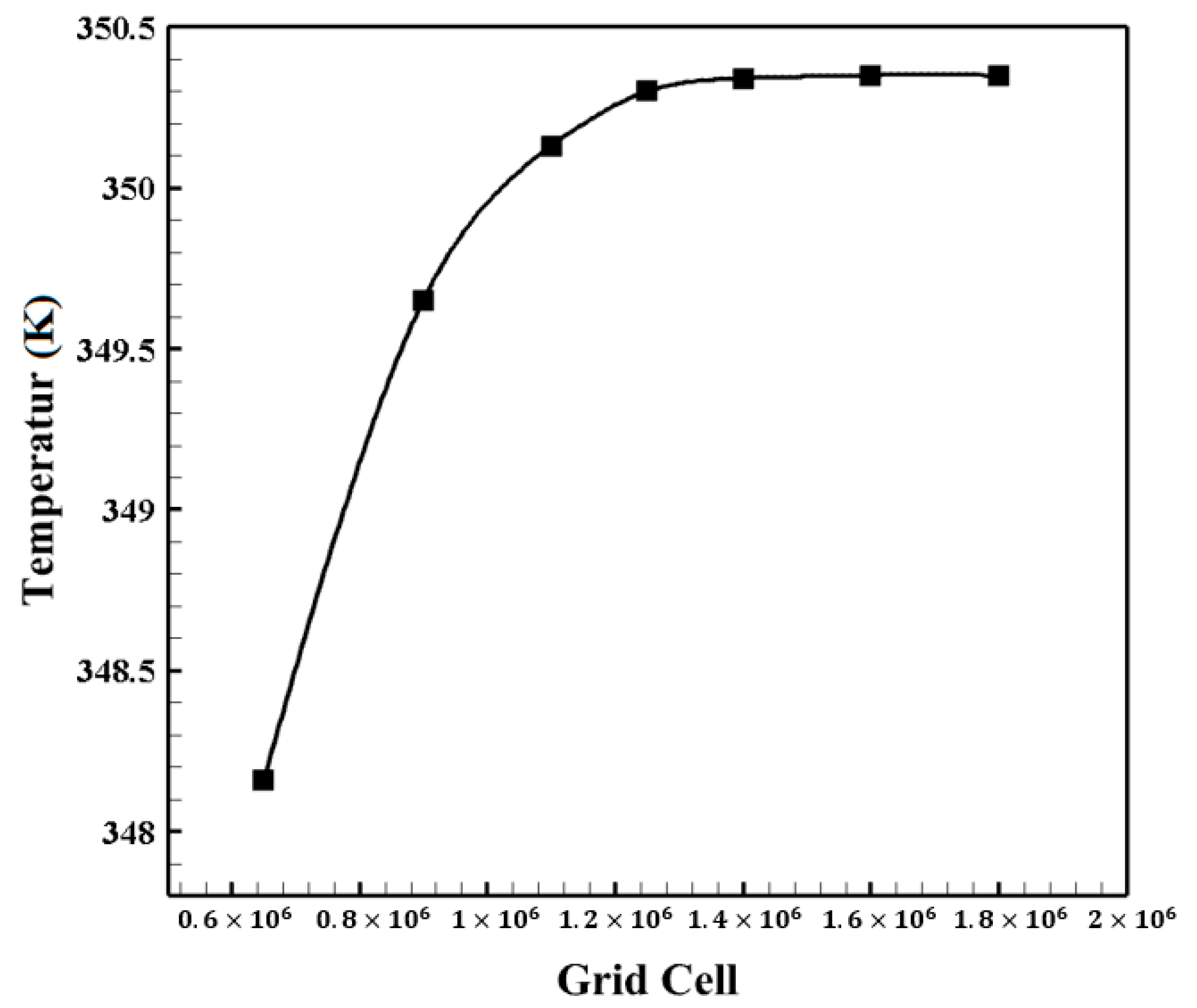
3.1. Mesh Independence Evaluation

To analysis, the grid size independence, the inlet temperature of the hot and cold streams is 360 and 300 K, respectively. The generated grid for the posed case is displayed in Figure 5. Consequently, it may be argued that the boundary layer grid is employed to augment the precision of the outcomes. Six grids with various cell sizes were generated for the analysis of grid independence. The comparison among the obtained outcomes is shown in Figure 6 in terms of the outlet temperature of the hot stream. It can be concluded that the grid with 1,400,000 cells could be considered for performing the simulations to save simulation time and cost.

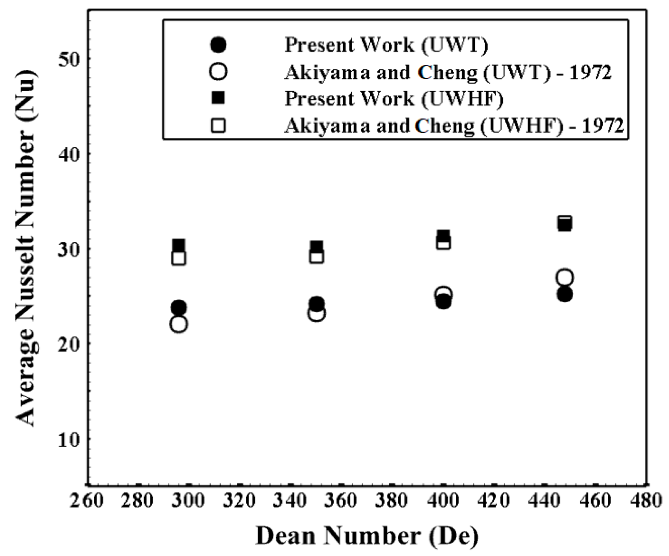
3.2. Validation Analysis

The empirical results of Akiyama and Cheng (hydrothermal behavior in a spiral tube) [46] were used to validate the numerical model employed. In the empirical work, two different boundary conditions with constant heat flux and constant temperature for the wall of the spiral tube were considered. Thus, the validation analysis was performed for both of them. The results of the validation analysis are revealed in Figure 7, where the numerical outcomes of the present work are compared with the empirical outcomes [46]. Consequently, it resulted that the present numerical model has acceptable precision as the maximum error among the numerical method and the empirical outcomes is 9.1%. It should be noted that the outcomes of both empirical (Akiyama and Cheng [46]) and numerical (present study) works were presented in the laminar regime.

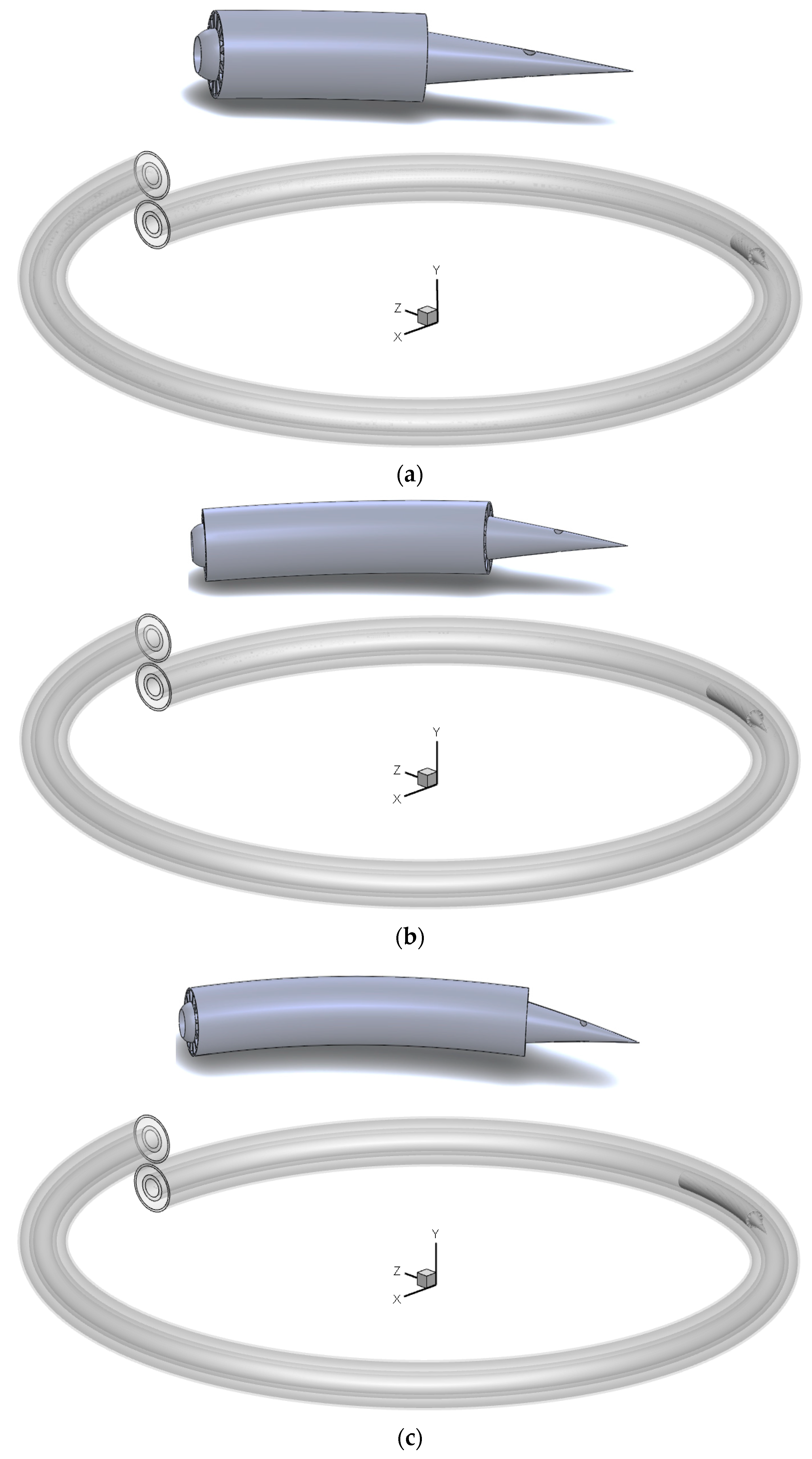
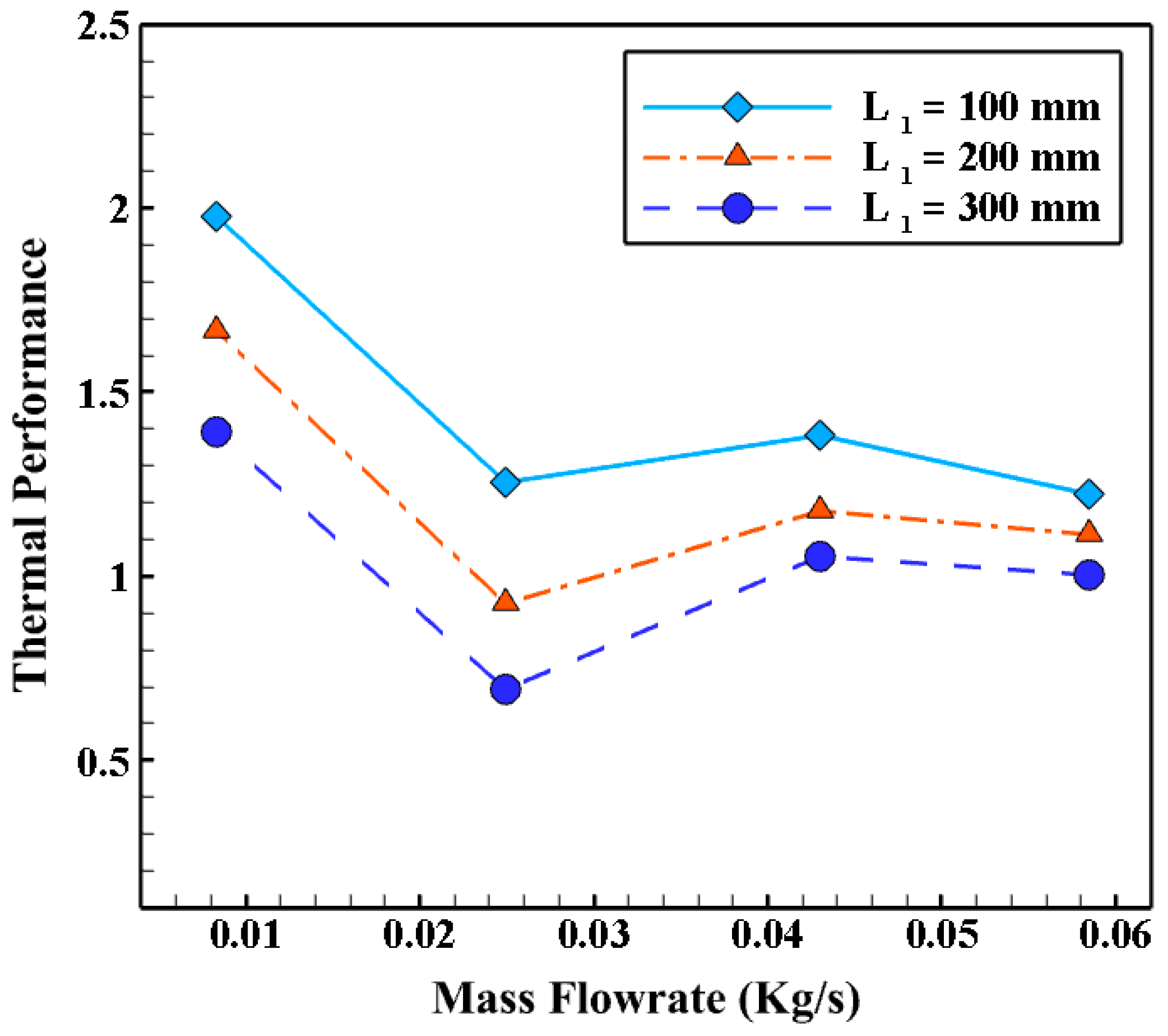
3.3. The Impact of the Proposed Swirl Generator’s Length (L1)

In this section, the effects of the length of the swirl generator used (L1) and the mass flow rate of the working fluid are evaluated. Three swirl generator lengths, namely, 100, 200, and 300 mm, are selected. Moreover, the obtained results are presented for four different mass flows. The schematics of the swirl generators with different lengths evaluated here are illustrated in Figure 3.
The profiles of average Nusselt numbers against mass flow rate for various lengths of swirl generators are shown in Figure 8. It can be observed that the use of the suggested vortex generator with each length value leads to a growth in the average Nusselt number and heat transfer coefficient compared to the case without a swirl generator since the generated swirling flows downstream of the swirl generator cause a higher heat transfer rate among the fluid flow and the interface among the hot and cold flows. In addition, the outcomes demonstrate that the average Nusselt number and heat transfer coefficient rise with increasing mass flow rate in each model, with this increase being more pronounced at lower mass flow rates. In addition, the average Nusselt number and heat transfer coefficient decrease as the length of the swirl generator increases. Consequently, the maximum heat transfer rate in the case L1 = 100 mm is recorded at the highest mass flow rate considered.
When a swirl generator of greater length is used, more secondary flows are produced in the central region of the pipe. This reduces the contact area between the fluid and the interface of the two flows, resulting in a lower heat transfer rate. On the other hand, the outlet flows from the swirl generator holes cause the flows generated (by the swirl generator vanes) to contact the interface of the two flows more (due to the collision of the following two flows: outlet flow from the vortex generator vanes and outlet flows from the vortex generator holes), resulting in a higher heat transfer rate. Consequently, a longer length of the swirl generator results in the outlet flows from the blades (generated swirl flows) being more dominant than the outlet flow from the holes. The fluid flow downstream of the swirl generator passes through the tube with a swirling motion in the middle of the pipe, and the interface between the two flows decreases. To better see the effects of the swirl generator used on the hydrothermal behavior, the streamline of the fluid flow for different views is shown in Figure 9.
Figure 9 illustrates that the proposed turbulator has two different parts, including the fluid passage area over the spiral blades and the internal channel. The outlet ports of the inner channel end in a spiral cone-shaped area, and at the end of it, there are two mutual holes, and the flow passing through the inner channel of the turbulator exits from these two holes. Moreover, from Figure 9, it can be seen that the swirling flows created behind the inserted swirl generation are a combination of the following two different swirling flows: (i) vortices produced by the holes of the conical sector and (ii) the vortex flows produced by the flow over the blades. In fact, the collision of the vortices created from the two outlet ducts of the turbulator leads to the rotating flow being drawn towards the wall and the boundary layer of the wall collapses, and the temperature gradient in the boundary layer increases; as a result, the heat transfer rate between the internal fluid and the pipe wall rises, and subsequently, further heat can be transferred rate among both streams.
The profiles of the pressure loss and friction factor against mass flow rate for various lengths of the swirl generator are shown in Figure 10a,b. As can be seen in Figure 10a, the pressure loss increases with increasing mass flow rate. In addition, the pressure loss increases as the swirl generator is used, and this growth in pressure loss is amplified as the length of the swirl generator decreases. It should be noted that a swirl generator with a shorter length blocks the flow more and consequently causes a further pressure loss. On the other hand, a swirl generator with greater length causes the fluid flow to adapt to the passage so that the pressure loss decreases.
Figure 10b shows that the evolution of pressure loss and friction factor against mass flow rate is exactly the opposite. As the mass flow rate increases, the friction factor rises; however, the pressure loss rises.
The temperature curves at the outlets (of both streams) of the inserted heat exchanger for different lengths of the inserted swirl generator are displayed in Figure 11. It must be noted that the temperature at the outlet is further unified by using a swirl generator with a shorter length, which has better heat transfer. As the length of the swirl generator increases, the secondary streams are centralized only in the central region of the spiral tube. This reduces the contact area between the flow and the partition, resulting in lower heat transfer. The discrepancy among the temperature contours for the models with L1 = 100 and 200 mm is small. However, the differences between the above cases with L1 = 300 mm are significant, which can be clearly seen in Figure 11.
The most important parameter for analyzing the effects of a method of improving heat transfer is thermal performance (Equation (6)), where the improvement in heat transfer and the pressure loss associated with the method used are calculated simultaneously. It is worth noting that a value for thermal power greater than one means that the application of the proposed heat transfer enhancement method demonstrates a much larger influence on heat transfer compared to the detrimental impact on pressure loss. Thus, the proposed heat transfer enhancement method is feasible. The deviations of thermal performance versus mass flow rates for different lengths are shown in Figure 12. Accordingly, the thermal performances of the swirl generator with L1 = 100 and 200 mm are greater than the unity for all values of the flows. Moreover, the used swirl generator with L1 = 100 mm at m ˙ = 0.008 and 0.05842 kg/s (as the lowest and highest mass flow rates considered) has a thermal power higher than the model without swirl generator by 100% and 20%, respectively. On the other hand, the model with L1 = 100 mm demonstrates the maximum thermal performance.

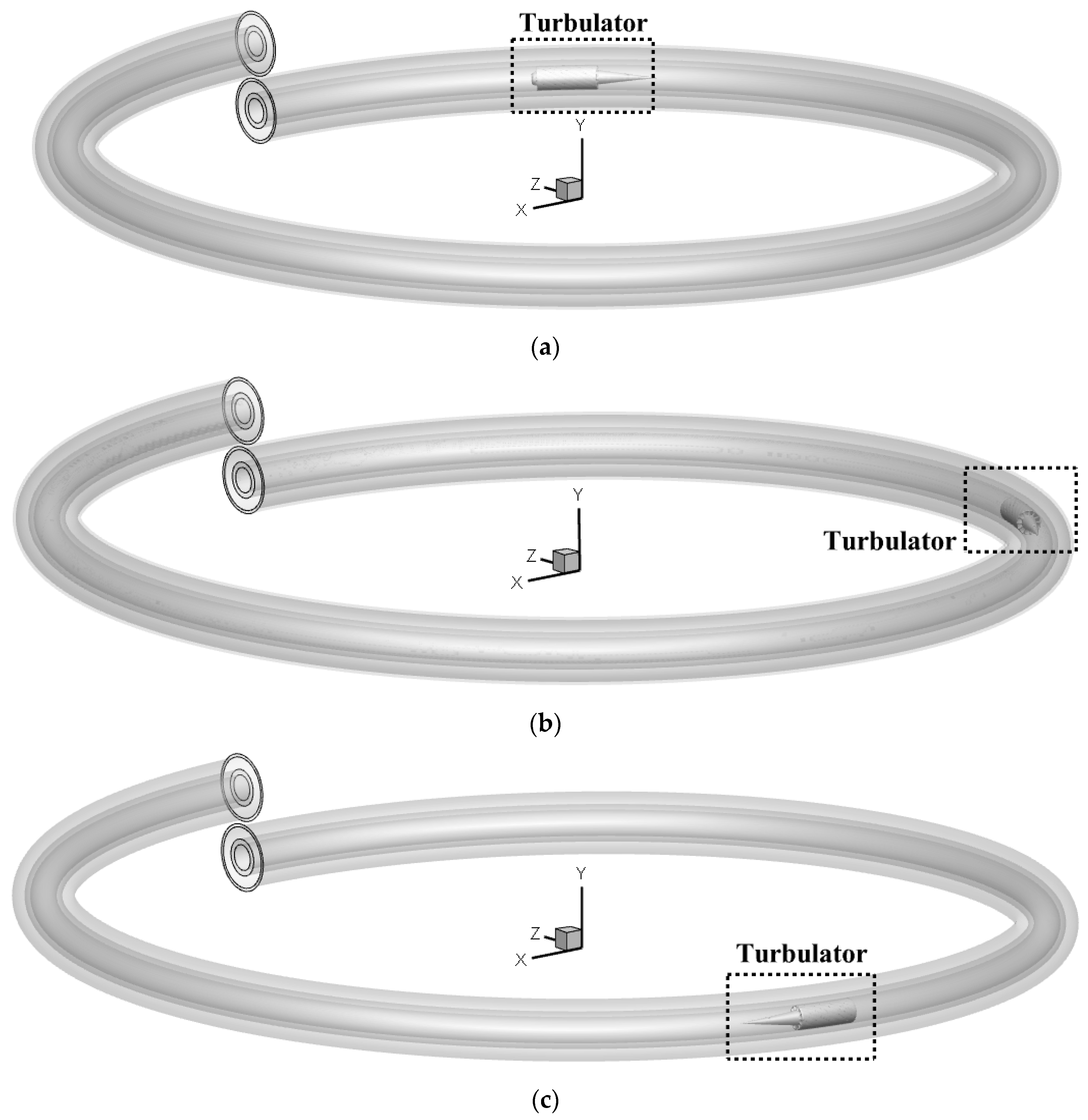
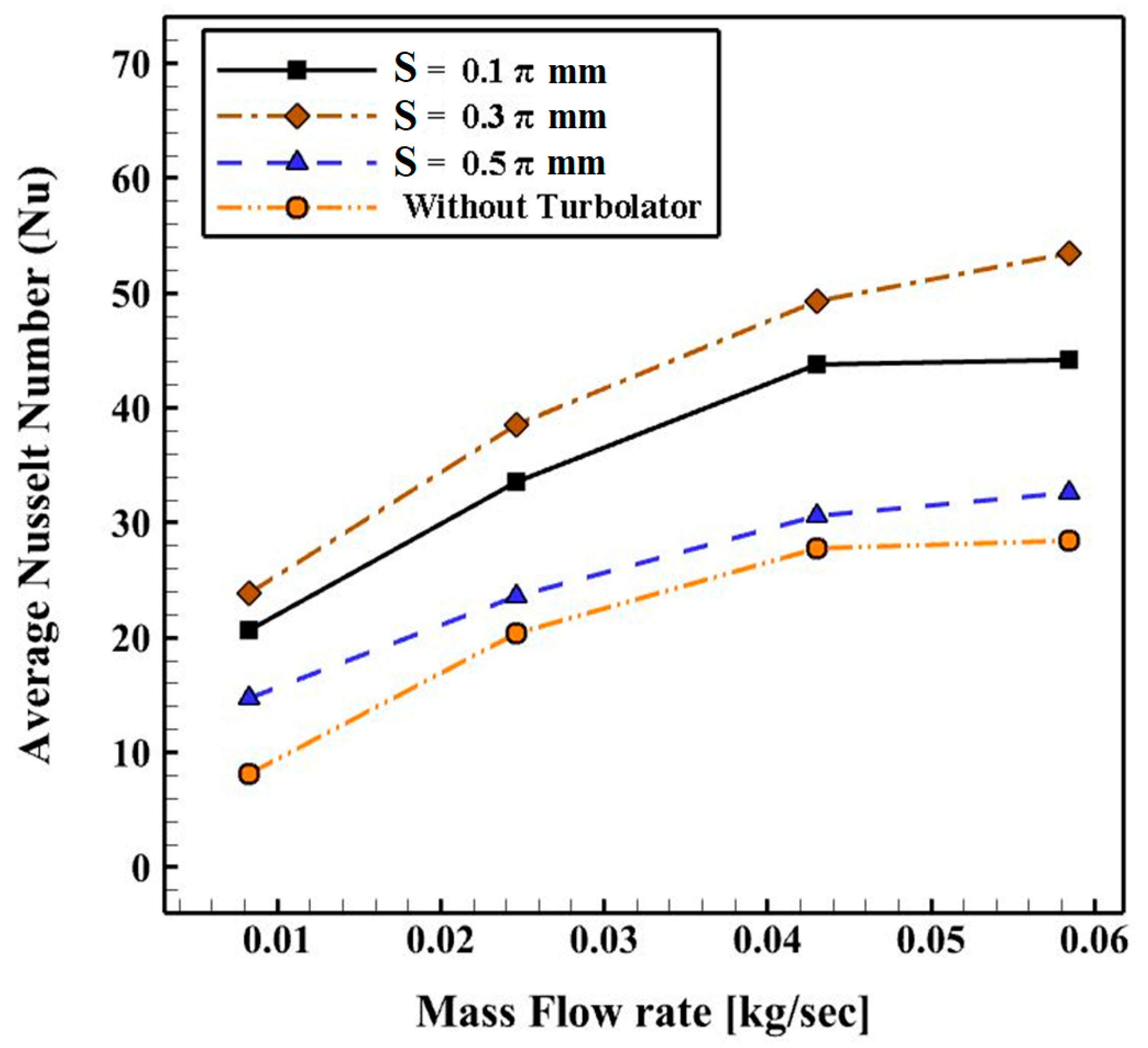
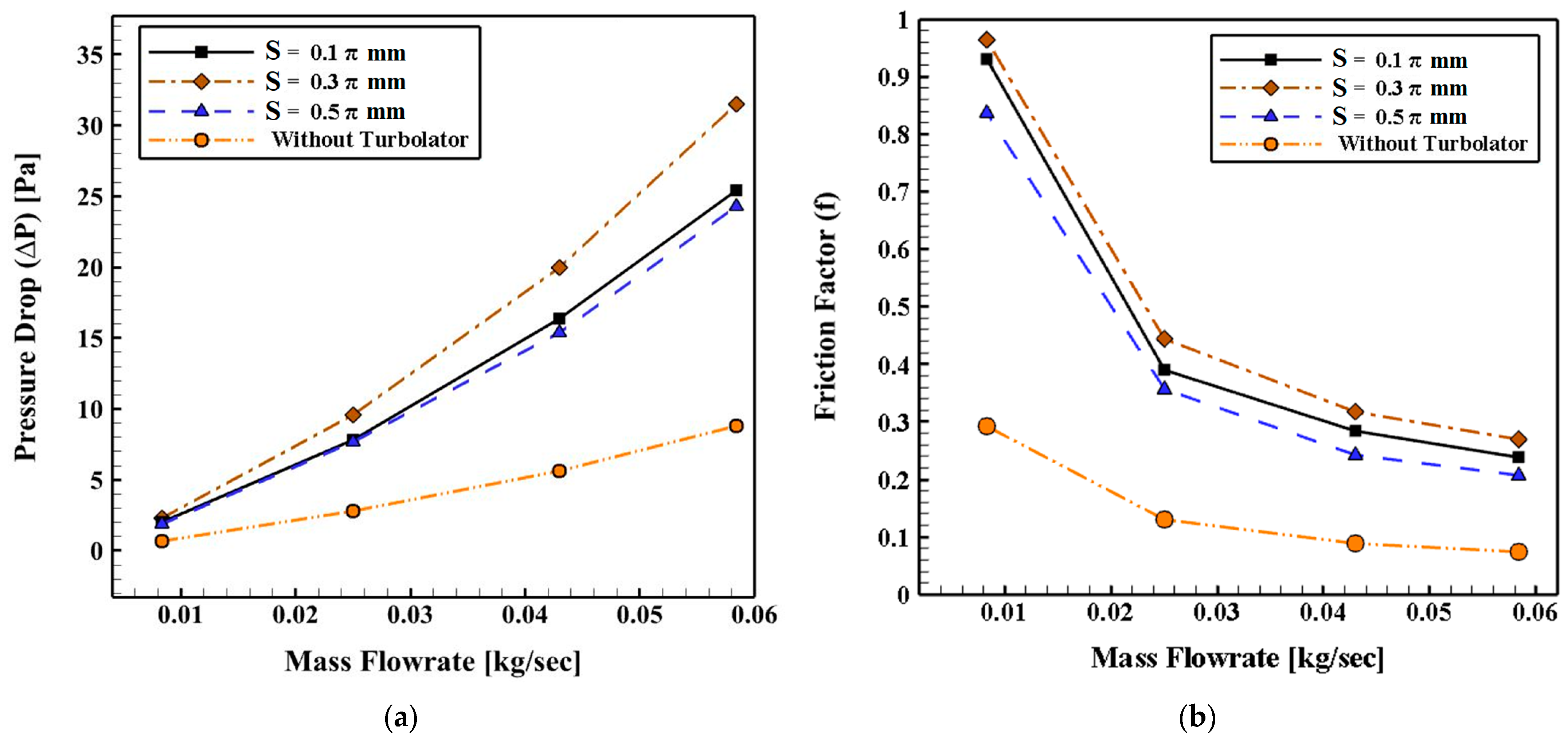
3.4. The Influence of the Position of the Suggested Swirl Generator (S)

Here, the influences of the position of the swirl generator (S) on the increase in heat transfer are investigated. Three different positions with S = 0.1π, 0.3π, and 0.5π mm are investigated here. According to the last section (Section 3.3), the used swirl generator with L1 = 100 mm is considered here. The schematics of the computational domain with different positions of the swirl generator used in this study are shown in Figure 4. The swirl generator position parameter (S) is clearly shown in Figure 13.
The profiles of the average Nusselt number against mass flow rate for different positions of the vortex generator used are displayed in Figure 14. It must be noted that there is no continuous trend for the average Nusselt number and heat transfer coefficient. In contrast, increasing or decreasing the distance between the inlet ports and the position of the swirl generator does not increase or decrease the average Nusselt number and heat transfer coefficient with a continuous trend. Moreover, it may be observed that the maximum heat transfer coefficient and the average Nusselt number apply to the model with S = 0.3π mm for all mass flow rates evaluated. The case with S = 0.1π mm is located in the second plane in Figure 14. The lowest average Nusselt number and the lowest heat transfer coefficient are obtained for the model with S = 0.5π mm for all mass flows studied. In other words, the placement of the swirl generator used near the inlet or outlet ports results in a poor heat transfer rate, and it should be placed at a specific position approximately in the middle of the distance between the inlet and outlet ports.
The contours of temperature at the exits for different positions of the employed swirl generator are demonstrated in Figure 15. Accordingly, a more uniform temperature can be achieved by employing the swirl generator with S = 0.3π mm. Moreover, it is depicted that a case with S = 0.1π mm is placed at the second level. The differences between cases S = 0.1π and 0.3π mm with S = 0.5π are significant (as same as the presented results in Figure 14).
The profiles of pressure loss and friction factor against mass flow rate for various positions of the swirl generator used are shown in Figure 16a,b. As can be seen from Figure 16a, all the studied cases depict greater pressure loss than the case without a swirl generator. Among the considered models, the model with S = 0.3π mm has the highest pressure loss for all evaluated mass flow rates. The model with S = 0.1π mm is in the second stage, and the difference between it and the case with S = 0.5π mm is small. Figure 16b shows the same trend in the models with the different positions of the used swirl generator. In contrast, the maximum and minimum coefficient of friction among the evaluated models are obtained in the cases S = 0.3π mm and S = 0.5π mm, respectively.
The profiles of thermal performance against mass flow rates for different positions of the swirl generator used are presented in Figure 17. It may be observed that for two models, including S = 0.1π mm and S = 0.3π mm, all thermal power values are greater than 1, indicating the advantages of the used swirl generator for hydrothermal power enhancement in the spiral double pipe heat exchanger in these positions. However, the case with S = 0.5π mm shows a thermal performance below unity (η < 1) for all mass flow rates considered except m ˙ = 0.008   kg / s .

4. Conclusions

In this study, the influence of a novel curved vortex generator on the hydrothermal behavior in a helical double-tube heat exchanger was investigated. The utilized swirl generator contains some blades to generate secondary flows (swirl flows). Moreover, two holes were made in the conical part of the swirl generator to produce more swirl flows. In this work, the influences of two geometrical factors, which contain the length of the proposed swirl generator and the position of the inserted swirl generator, on the thermal performance of the proposed heat exchanger were studied. The obtained results are as follows:
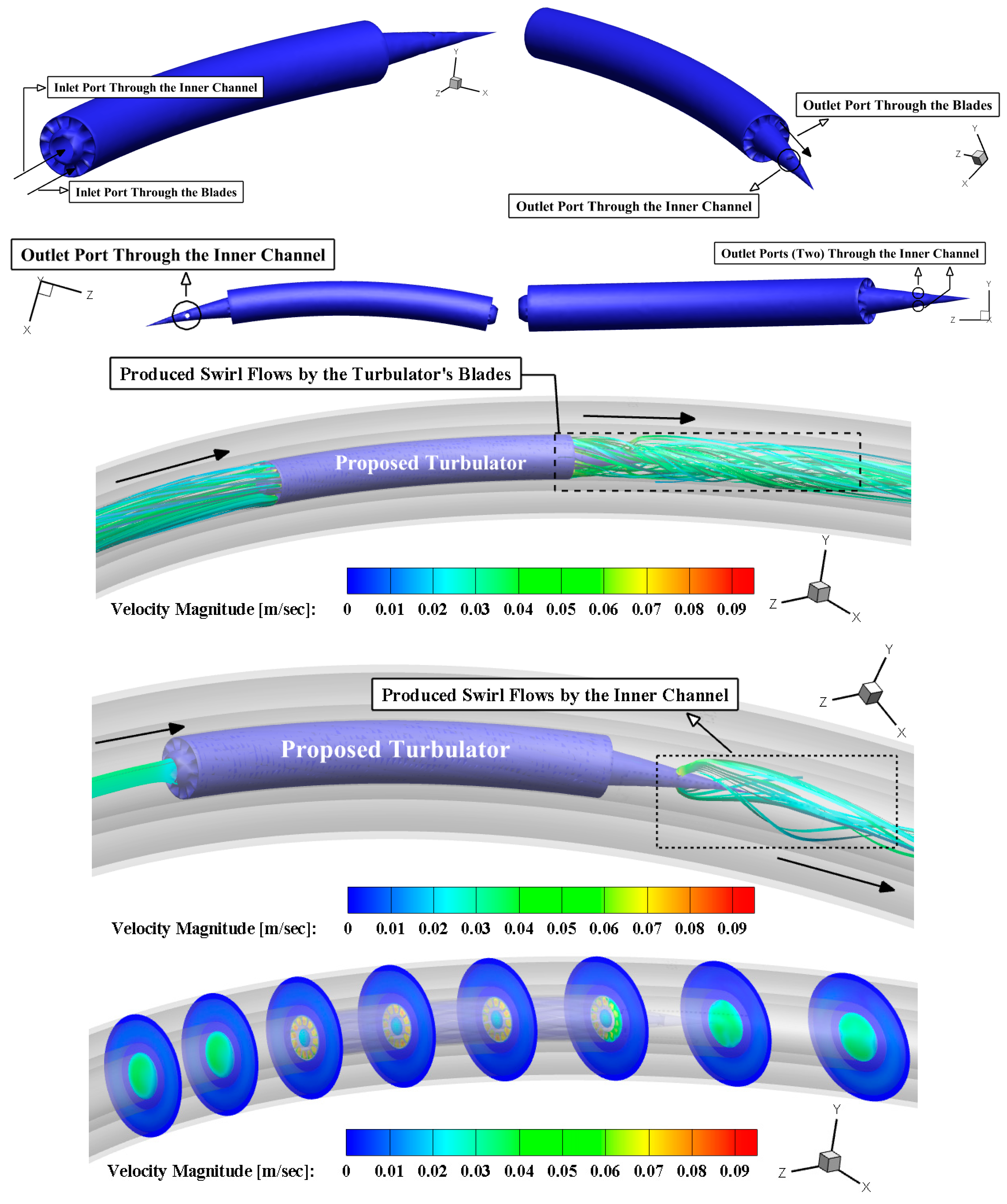
  • The generated secondary flows (swirls) were a mixture of the swirls caused by the holes of the conical sector and the secondary streams caused by the blades;
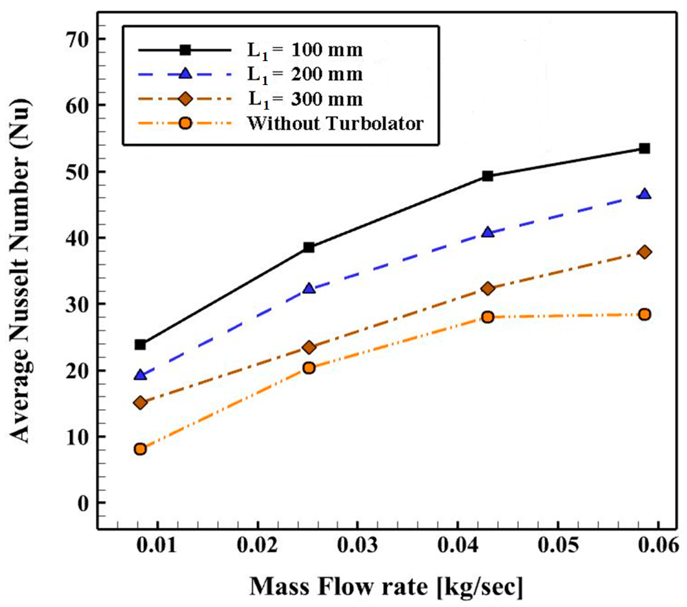
  • The shorter length of the employed swirl generator resulted in higher thermal performance;
  • The maximum thermal performance belonged to the model with L1 = 100 mm at m ˙ = 0.008 kg/s by 17.65, 53.85, and 100%, respectively, compared to the models L1 = 200, 300 mm, and the model without swirl generator;
  • The best thermal stratification was obtained at L1 = 100 mm, and the temperature contour showed a uniform temperature field distribution for this case;
  • Among the different studied positions of the inserted swirl generator, the maximum heat transfer coefficient and the average Nusselt number in all mass flows were found at the position S = 0.3π mm;
  • Only two positions of the inserted swirl generator, including S = 0.1π and 0.3π mm, illustrated more thermal performance compared to the model without a swirl generator;
  • The thermal performance of the case with position S = 0.3π mm was higher than that of the case S = 0.1π mm, S = 0.5π mm, and the case without swirl generator by about 11.11, 53.84, and 100%, respectively.

Author Contributions

Conceptualization, S.S.M.A. and S.H.H.K.; methodology, S.S.M.A. and S.H.H.K.; software, S.S.M.A. and S.H.H.K.; validation, S.S.M.A. and S.H.H.K.; formal analysis, S.S.M.A. and S.H.H.K.; investigation, S.S.M.A. and S.H.H.K.; resources, S.S.M.A. and M.A.-k.; data curation, S.S.M.A., A.A.K., and M.A.-k.; writing—original draft preparation, S.S.M.A.; writing—review and editing, S.S.M.A., M.A.-k., M.M.Z., and K.S.; visualization, S.S.M.A., A.A.K., and M.M.Z.; supervision, S.S.M.A. and K.S.; project administration, S.S.M.A. All authors have read and agreed to the published version of the manuscript.

Funding

This research received no external funding.

Data Availability Statement

The datasets generated during and/or analyzed during the current study are available from the corresponding author on reasonable request.

Conflicts of Interest

The authors declare no conflict of interest.

References

  1. Ajarostaghi, S.S.M.; Mousavi, S.S. Solar energy conversion technologies: Principles and advancements. In Solar Energy Advancements in Agriculture and Food Production Systems; Academic Press: Cambridge, MA, USA, 2022; pp. 29–76. [Google Scholar] [CrossRef]
  2. Amirsoleymani, A.; Babaei, R.; Mousavi Ajarostaghi, S.S.; Saffari Pour, M. Feasibility evaluation of Stand-Alone energy solutions in Energy-Poor Islands using sustainable hydrogen production. Int. J. Energy Res. 2022, 46, 24045–24063. [Google Scholar] [CrossRef]
  3. Norouztabar, R.; Mousavi Ajarostaghi, S.S.; Mousavi, S.S.; Nejat, P.; Rahimian Koloor, S.S.; Eldessouki, M. On the performance of a modified triple stack blade Savonius wind turbine as a function of geometrical parameters. Sustainability 2022, 14, 9816. [Google Scholar] [CrossRef]
  4. Ezoji, H.; Ajarostaghi, S.S.M. Thermodynamic-CFD analysis of waste heat recovery from homogeneous charge compression ignition (HCCI) engine by Recuperative organic Rankine Cycle (RORC): Effect of operational parameters. Energy 2020, 205, 117989. [Google Scholar] [CrossRef]
  5. Berger, S.A.; Talbot, L.; Yao, L.S. Flow in curved pipes. Annu. Rev. Fluid Mech. 1983, 15, 461–512. [Google Scholar] [CrossRef]
  6. Mousavi Ajarostaghi, S.S.; Zaboli, M.; Javadi, H.; Badenes, B.; Urchueguia, J.F. A review of recent passive heat transfer enhancement methods. Energies 2022, 15, 986. [Google Scholar] [CrossRef]
  7. Esfe, M.H.; Saedodin, S.; Wongwises, S.; Toghraie, D. An experimental study on the effect of diameter on thermal conductivity and dynamic viscosity of Fe/water nanofluids. J. Therm. Anal. Calorim. 2015, 119, 1817–1824. [Google Scholar] [CrossRef]
  8. Afsharpanah, F.; Izadi, M.; Hamedani, F.A.; Ajarostaghi, S.S.M.; Yaïci, W. Solidification of nano-enhanced PCM-porous composites in a cylindrical cold thermal energy storage enclosure. Case Stud. Therm. Eng. 2022, 39, 102421. [Google Scholar] [CrossRef]
  9. Afsharpanah, F.; Cheraghian, G.; Akbarzadeh Hamedani, F.; Shokri, E.; Mousavi Ajarostaghi, S.S. Utilization of carbon-based nanomaterials and plate-fin networks in a cold PCM container with application in air conditioning of buildings. Nanomaterials 2022, 12, 1927. [Google Scholar] [CrossRef]
  10. Afsharpanah, F.; Mousavi Ajarostaghi, S.S.; Akbarzadeh Hamedani, F.; Saffari Pour, M. Compound heat transfer augmentation of a shell-and-coil ice storage unit with metal-oxide nano additives and connecting plates. Nanomaterials 2022, 12, 1010. [Google Scholar] [CrossRef] [PubMed]
  11. Noorbakhsh, M.; Pourfallah, M.; Ajarostaghi, S.S.; Zaboli, M. Numerical evaluation and the effects of geometrical and operational parameters on thermal performance of the shell and double coil tube heat exchanger. Heat Transf. 2020, 49, 4678–4703. [Google Scholar] [CrossRef]
  12. Afsharpanah, F.; Pakzad, K.; Mousavi Ajarostaghi, S.S.; Poncet, S.; Sedighi, K. Accelerating the charging process in a shell and dual coil ice storage unit equipped with connecting plates. Int. J. Energy Res. 2022, 46, 7460–7478. [Google Scholar] [CrossRef]
  13. Kim, K.; Lee, K.S. Frosting and defrosting characteristics of surface-treated louvered-fin heat exchangers: Effects of fin pitch and experimental conditions. Int. J. Heat Mass Transf. 2013, 60, 505–511. [Google Scholar] [CrossRef]
  14. Nuntaphan, A.; Vithayasai, S.; Vorayos, N.; Vorayos, N.; Kiatsiriroat, T. Use of oscillating heat pipe technique as extended surface in wire-on-tube heat exchanger for heat transfer enhancement. Int. Commun. Heat Mass Transf. 2010, 37, 287–292. [Google Scholar] [CrossRef]
  15. Salhi, J.E.; Mousavi Ajarostaghi, S.S.; Zarrouk, T.; Saffari Pour, M.; Salhi, N.; Salhi, M. Turbulence and thermos-flow behavior of air in a rectangular channel with partially inclined baffles. Energy Sci. Eng. 2022, 10, 3540–3558. [Google Scholar] [CrossRef]
  16. Nouri Kadijani, O.; Kazemi Moghadam, H.; Mousavi Ajarostaghi, S.S.; Asadi, A.; Saffari Pour, M. Hydrothermal performance of humid air flow in a rectangular solar air heater equipped with V-shaped ribs. Energy Sci. Eng. 2022, 10, 2276–2289. [Google Scholar] [CrossRef]
  17. Samadifar, M.; Toghraie, D. Numerical simulation of heat transfer enhancement in a plate-fin heat exchanger using a new type of vortex generators. Appl. Therm. Eng. 2018, 133, 671–681. [Google Scholar] [CrossRef]
  18. Hobbi, A.; Siddiqui, K. Experimental study on the effect of heat transfer enhancement devices in flat-plate solar collectors. Int. J. Heat Mass Transf. 2009, 52, 4650–4658. [Google Scholar] [CrossRef]
  19. Dizaji, H.S.; Jafarmadar, S.; Asaadi, S. Experimental exergy analysis for shell and tube heat exchanger made of corrugated shell and corrugated tube. Exp. Therm. Fluid Sci. 2017, 81, 475–481. [Google Scholar] [CrossRef]
  20. Mohammadi, S.; Mousavi Ajarostaghi, S.S.; Pourfallah, M. The latent heat recovery from boiler exhaust flue gas using shell and corrugated tube heat exchanger: A numerical study. Heat Transf. 2020, 49, 3797–3815. [Google Scholar] [CrossRef]
  21. Li, J.; Hrnjak, P. Separation in condensers as a way to improve efficiency. Int. J. Refrig. 2017, 79, 1–9. [Google Scholar] [CrossRef]
  22. Li, H.; Wang, L.; Jiang, H.; Liu, H.; Gao, Q.; Huang, L. Quantification of flow distribution and heat capacity potential of a microchannel evaporator. Int. J. Refrig. 2022; in press. [Google Scholar] [CrossRef]
  23. Li, H.; Hrnjak, P. Transition from plug/slug flow to annular flow in microchannel tube: A database and a model. Int. J. Heat Mass Transf. 2022, 193, 122997. [Google Scholar] [CrossRef]
  24. Tang, L.H.; Zeng, M.; Wang, Q.W. Experimental and numerical investigation on air-side performance of fin-and-tube heat exchangers with various fin patterns. Exp. Therm. Fluid Sci. 2009, 33, 818–827. [Google Scholar] [CrossRef]
  25. Wongcharee, K.; Eiamsa-ard, S. Heat transfer enhancement by using CuO/water nanofluid in corrugated tube equipped with twisted tape. Int. Commun. Heat Mass Transf. 2012, 39, 251–257. [Google Scholar] [CrossRef]
  26. Darzi, A.A.R.; Farhadi, M.; Sedighi, K. Experimental investigation of convective heat transfer and friction factor of Al2O3/water nanofluid in helically corrugated tube. Exp. Therm. Fluid Sci. 2014, 57, 188–199. [Google Scholar] [CrossRef]
  27. Du, T.; Chen, Q.; Du, W.; Cheng, L. Performance of continuous helical baffled heat exchanger with varying elliptical tube layouts. Int. J. Heat Mass Transf. 2019, 133, 1165–1175. [Google Scholar] [CrossRef]
  28. Bahiraei, M.; Mazaheri, N.; Rizehvandi, A. Application of a hybrid nanofluid containing graphene nanoplatelet–platinum composite powder in a triple-tube heat exchanger equipped with inserted ribs. Appl. Therm. Eng. 2019, 149, 588–601. [Google Scholar] [CrossRef]
  29. Abolarin, S.M.; Everts, M.; Meyer, J.P. Heat transfer and pressure drop characteristics of alternating clockwise and counter clockwise twisted tape inserts in the transitional flow regime. Int. J. Heat Mass Transf. 2019, 133, 203–217. [Google Scholar] [CrossRef]
  30. Zhang, Y.; Zhou, F.; Kang, J. Flow and heat transfer in drag-reducing polymer solution flow through the corrugated tube and circular tube. Appl. Therm. Eng. 2020, 9, 115185. [Google Scholar] [CrossRef]
  31. Kareem, Z.S.; Abdullah, S.; Lazim, T.M.; Jaafar, M.M.; Wahid, A.F. Heat transfer enhancement in three-start spirally corrugated tube: Experimental and numerical study. Chem. Eng. Sci. 2015, 134, 746–757. [Google Scholar] [CrossRef]
  32. Lu, G.; Zhou, G. Numerical simulation on performances of plane and curved winglet type vortex generator pairs with punched holes. Int. J. Heat Mass Transf. 2016, 102, 679–690. [Google Scholar] [CrossRef]
  33. Mashoofi, N.; Pesteei, S.M.; Moosavi, A.; Dizaji, H.S. Fabrication method and thermal-frictional behavior of a tube-in-tube helically coiled heat exchanger which contains turbulator. Appl. Therm. Eng. 2017, 111, 1008–1015. [Google Scholar] [CrossRef]
  34. Noorbakhsh, M.; Zaboli, M.; Ajarostaghi, S.S. Numerical evaluation of the effect of using twisted tapes as turbulator with various geometries in both sides of a double-pipe heat exchanger. J. Therm. Anal. Calorim. 2020, 140, 1341–1353. [Google Scholar] [CrossRef]
  35. Kwon, B.; Liebenberg, L.; Jacobi, A.M.; King, W.P. Heat transfer enhancement of internal laminar flows using additively manufactured static mixers. Int. J. Heat Mass Transf. 2019, 137, 292–300. [Google Scholar] [CrossRef]
  36. Rashidi, S.; Hormozi, F.; Sundén, B.; Mahian, O. Energy saving in thermal energy systems using dimpled surface technology—A review on mechanisms and applications. Appl. Energy 2019, 250, 1491–1547. [Google Scholar] [CrossRef]
  37. Hashemi Karouei, S.H.; Seyed Soheil, M.A. Influence of a Curved Conical Turbulator on Heat Transfer Augmentation in a Helical Double-Pipe Heat Exchanger. J. Heat Transf. Asian Res. 2020, 50, 1872–1894. [Google Scholar] [CrossRef]
  38. Hashemi Karouei, S.H.; Ajarostaghi, S.S.M.; Gorji-Bandpy, M.; Hosseini Fard, S.R. Laminar heat transfer and fluid flow of two various hybrid nanofluids in a helical double-pipe heat exchanger equipped with an innovative curved conical turbulator. J. Therm. Anal. Calorim. 2021, 143, 1455–1466. [Google Scholar] [CrossRef]
  39. Hashemi Karouei, S.H.; Mousavi Ajarostaghi, S.S.; Rashidi, S.; Hosseinirad, E. An advanced turbulator with blades and semi-conical section for heat transfer improvement in a helical double tube heat exchanger. J. Cent. South Univ. 2021, 28, 3491–3506. [Google Scholar] [CrossRef]
  40. Bejan, A. Convection Heat Transfer; John Wiley & Sons: Hoboken, NJ, USA, 2013; ISBN 978-1-118-33008-1. [Google Scholar]
  41. Schmidt, E.F. Wärmeübergang und druckverlust in rohrschlangen. Chem. Ing. Tech. 1967, 39, 781–789. [Google Scholar] [CrossRef]
  42. Itō, H. Friction factors for turbulent flow in curved pipes. J. Basic Eng. 1959, 81, 123–132. [Google Scholar] [CrossRef]
  43. Lim, K.Y.; Hung, Y.M.; Tan, B.T. Performance evaluation of twisted-tape insert induced swirl flow in a laminar thermally developing heat exchanger. Appl. Therm. Eng. 2017, 121, 652–661. [Google Scholar] [CrossRef]
  44. Zheng, N.; Liu, P.; Shan, F.; Liu, J.; Liu, Z.; Liu, W. Numerical studies on thermo-hydraulic characteristics of laminar flow in a heat exchanger tube fitted with vortex rods. Int. J. Therm. Sci. 2016, 100, 448–456. [Google Scholar] [CrossRef]
  45. Guo, J.; Fan, A.; Zhang, X.; Liu, W. A numerical study on heat transfer and friction factor characteristics of laminar flow in a circular tube fitted with center-cleared twisted tape. Int. J. Therm. Sci. 2011, 50, 1263–1270. [Google Scholar] [CrossRef]
  46. Akiyama, M.; Cheng, K.C. Laminar forced convection heat transfer in curved pipes with uniform wall temperature. Int. J. Heat Mass Transf. 1972, 15, 1426–1431. [Google Scholar] [CrossRef]
Figure 1. The schematics of the geometries of the helical double pipe heat exchanger and employed swirl generator; (a) the 2D-view of the heat exchanger’s cross-section with geometric factors, and (b) the 3D-view of the computational domain.
Energies 16 01801 g001
Figure 2. The 3D-views of the employed curved swirl generator and 2D-view of the swirl generator’s cross-section with geometric factors.
Energies 16 01801 g002
Figure 3. The configuration of the swirl generators with various lengths at n = 12, θ = 180 degrees, and S = 0.3π mm; (a) L1 = 100 mm, (b) L1 = 200 mm, and (c) L1 = 300 mm.
Energies 16 01801 g003
Figure 4. The graphics of the swirl generators with various positions at n = 12, θ = 180 degrees, and L1 = 100 mm; (a) S = 0.1π mm, (b) S = 0.3π mm, and (c) S = 0.5π mm.
Energies 16 01801 g004
Figure 5. The pictures of the produced grid at various views of the proposed heat exchanger.
Energies 16 01801 g005
Figure 6. The obtained results of the mesh independence analysis.
Energies 16 01801 g006
Figure 7. The outcomes of the verification investigation.
Energies 16 01801 g007
Figure 8. The deviations of average Nusselt number versus the mass flow rates for various cases (L1) at n = 12, θ = 180 degrees, and S = 0.3π mm.
Energies 16 01801 g008
Figure 9. The produced secondary (swirl) flows with contours of temperature and velocity magnitude from the exit of swirl generator’s holes, and the fluid flow over the blades.
Energies 16 01801 g009aEnergies 16 01801 g009b
Figure 10. The deviations of (a) pressure loss and (b) friction factor versus the mass flow rates for various lengths of swirl generator at n = 12, θ = 180 degrees, and S = 0.3π mm.
Energies 16 01801 g010
Figure 11. The temperature contours at outlet ports for different lengths of proposed swirl generator (L1) at S = 0.3π mm at m ˙ = 0.043 kg/s.
Energies 16 01801 g011
Figure 12. The deviations of thermal performance versus the mass flow rates for various lengths of swirl generator at n = 12, θ = 180 degrees, and S = 0.3π mm.
Energies 16 01801 g012
Figure 13. The definition of swirl generator position parameter (S).
Energies 16 01801 g013
Figure 14. The deviations of average Nusselt number versus mass flow rates for various positions of the proposed swirl generator at θ = 180 degrees, n = 12, R0 = 19 mm, r = 8.4 mm, L1 = 100 mm, and m ˙ = 0.043   kg / s .
Energies 16 01801 g014
Figure 15. The contours of temperature at exits for different position of proposed swirl generator at θ = 180 degrees, n = 12, R0 =19 mm, r = 8.4 mm, L1 = 100 mm, and m ˙ = 0.043 kg/s.
Energies 16 01801 g015
Figure 16. The deviations of (a) pressure loss and (b) friction factor with mass flow rates for various positions of the proposed swirl generator at θ = 180 degrees, n = 12, R0 =19 mm, r = 8.4 mm, L1 = 100 mm, and m ˙ = 0.043 kg/s.
Energies 16 01801 g016
Figure 17. The deviations of thermal performance versus the mass flow rates for various positions of the proposed swirl generator at θ = 180 degrees n = 12, R0 = 19 mm, r = 8.4 mm, L1 = 100 mm, and m ˙ = 0.043   kg / s .
Energies 16 01801 g017
Table 1. The values of the geometric factors of the computational domain.
PropertiesValue (mm)
Swirl Generator’s Outer Radius (Ro) 17
Swirl Generator’s Inner Radius (Ri) 12
Channel’s Radius of Swirl Generator (r) 6
Thickness of Swirl Generator’s Blades (w) 2
Height of Swirl Generator’s Blades (h) 5
Radius of Swirl Generator’s Holes (ri) 3
Cold Channel’s Diameter (Di) 0.1
Hot Channel’s Diameter (di) 0.042
The Radius of Heat Exchanger’s Round (R) 0.8
Table 2. The thermophysical characteristics of considered materials.
PropertyWater (Working Fluid)Steel (Swirl Generator)
Density (kg/m3)998.27881.8
Viscosity (Pa·s)0.001003-
Thermal Conductivity (W/(m·K)0.616.0
Specific Heat (J/ (kg·K)4181.8502.0
Table 3. Comparison results between turbulent and laminar flow regimes at two different Reynolds numbers.
Mass Flow rate [kg/s]ReAverage Nusselt NumberError [%]Friction Factor (f)Error [%]
LaminarTurbulentLaminarTurbulent
0.0250475733.534.312.48.18.504.8
0.05843170044.546.3542626.973.6
Disclaimer/Publisher’s Note: The statements, opinions and data contained in all publications are solely those of the individual author(s) and contributor(s) and not of MDPI and/or the editor(s). MDPI and/or the editor(s) disclaim responsibility for any injury to people or property resulting from any ideas, methods, instructions or products referred to in the content.

