Article

A Feasibility Study on Gravity Power Generation Technology by Virtue of Abandoned Oil-Gas Wells in China

1
CNPC Engineering Technology R&D Company Limited, Beijing 102206, China
2
State Key Laboratory of Advanced Processing and Recycling of Non-ferrous Metals, Lanzhou University of Technology, Lanzhou 730050, China
3
School of Mechanical Engineering, Yangtze University, Jingzhou 434023, China
*
Author to whom correspondence should be addressed.
Energies 2023, 16(4), 1575; https://doi.org/10.3390/en16041575
Submission received: 31 December 2022 / Revised: 25 January 2023 / Accepted: 1 February 2023 / Published: 4 February 2023
(This article belongs to the Special Issue Advances in the Utilization of Underground Energy and Space)

Abstract

:
In the future, there will be more and more abandoned oil-gas wells with the exploitation of onshore oilfield resources. However, the large height difference in abandoned oil-gas wells can be used as building blocks for gravity power generation, thus maximizing the economic value of abandoned oil-gas wells. In this study, a scheme of gravity power generation by virtue of the spud-in casing depth of oil-gas wells is proposed, and a gravity power generation model based on abandoned oil-gas wells is established. The parameters and economic benefits of gravity energy storage are calculated for oil-gas wells in the Huabei oilfield, the Daqing oilfield, and the Xinjiang oilfield. It is shown that the power density and discharge time of the gravity energy storage system in abandoned oil-gas wells are suitable for distributed power generation. In addition, the fast response characteristics of energy storage in abandoned oil-gas wells are verified, which makes the system suitable for correcting continuous and sudden frequency and voltage changes in the power grid but not suitable for energy arbitrage under a high number of annual cycles. Furthermore, the leveling cost of storage of the gravity system in abandoned oil-gas wells is more economical with the high number of annual cycles. The analysis of this work provides a significant investigation of the feasibility of gravity power generation by using abandoned oil-gas wells.

1. Introduction

With the implementation of the strategic goal of carbon dioxide peaking and carbon neutrality in China [1], new energy power generation techniques, such as wind power and photovoltaic power, have exhibited rapid growth. This puts forward higher requirements for energy storage technology. Energy storage, as a flexible peaking power regulation approach, can effectively hedge the fluctuation and security problems brought by new energy power generation and plays a key role in new energy consumption, peak regulation, and frequency regulation. In the “Guiding Instructions on Accelerating the Development of New Energy Storage” issued in China in July 2021, it was proposed that by 2025, the installed scale of new energy storage would reach more than 30 million kW [2]; by 2030, new energy storage would be fully marketed.
At present, the energy storage market in China mainly relies on pumping energy storage, and its market share is about 90% [3]. Although pumping storage has been proven to have a long-life cycle, it requires a large amount of land and needs to be located near water resources. Moreover, the pumping energy storage system is not extensible upon completion and faces significant challenges in meeting the expected market growth due to the high cost and environmental impacts of constructing man-made reservoirs [4]. Some chemical components in other forms of renewable energy storage technologies, such as lithium-ion battery technology, require scarce raw materials (such as cobalt) to produce batteries. This can be subject to cyclical supply chain challenges and has a high carbon footprint in transportation and production. Nevertheless, the chemical composition of batteries also degrades over time. Such batteries also contain harmful substances and pose safety and fire risks [5]. Similarly, geothermal energy storage and flow batteries require relatively high capital investments and high operating costs but have a relatively low efficiency level. Moreover, they are not modular and have geological limitations [6]. Table 1 gives a comparison of the parameters of common energy storage technologies.
In addition to the common energy storage methods mentioned above, gravity energy storage has attracted increasing attention in recent years. Compared with pumping energy storage, gravity storage systems mainly use customized “moving blocks” to replace water. They can increase the stored energy by stacking “moving blocks” and release energy by lowering the “moving blocks” back to the ground. This type of energy storage is completely free from the strict, low-quality requirements of pumped storage power stations, and the “moving blocks” can be made from various materials. Taking advantage of the existing shafts of abandoned oil-gas wells, the gravity of energy storage based on abandoned oil-gas wells was calculated, and the corresponding economic benefits are analyzed. Tong et al. have explained the important advantages of solid gravity energy storage, including the sustainability of this energy storage method which uses natural materials, produces no pollution, has no fire or explosion risk, and is safe and reliable [8]. In addition, Berrada et al. have conducted a life-cycle assessment of the large-scale application of gravity energy storage systems, for which there are no fuel and emissions-related costs because the systems do not consume fuel or generate carbon emissions during operation. Their detailed economic analysis also shows the cost competitiveness of gravity storage compared to pumped hydro energy storage and compressed air energy storage [9].
This paper mainly studies the feasibility of gravity energy storage in abandoned oil-gas wells and calculates the parameters and economic benefits of using this storage technique in oil-gas wells in the Huabei oilfield, the Daqing oilfield, and the Xinjiang oilfield. Based on the obtained results and analyses, some conclusions are drawn at the end of this paper.

2. Overview of Gravity Energy Storage Methods and Selection of Energy Storage Shafts

2.1. Basic Concepts of Gravity Energy Storage Technology

Gravity energy storage, a type of mechanical energy storage, uses energy storage media made of water and solid materials to charge and discharge the energy storage system by lifting and lowering the energy storage media based on height difference.
Due to the strong fluidity of water, the water-medium gravity energy storage system can make use of well-sealed pipes, shafts, and other structures. The flexibility of site selection and the energy storage capacity are limited by the terrain and water sources. In this regard, it is easier to build large-scale energy storage systems near natural water resources. A solid heavy-object gravity energy storage system mainly makes use of mountains, underground shafts, and artificial and other structures. The heavy objects are generally materials with a relatively high density, such as metal, cement, sand, and stone, specifically chosen to achieve a higher energy density.

2.2. Underground Shaft Gravity Energy Storage

Based on basic technical principles, gravity energy storage can be preliminarily divided into the following categories: new-type pumped energy storage and undersea energy storage; gravity energy storage based on the height differences of structures; gravity energy storage based on mountain drops; and gravity energy storage based on underground shafts; in addition to other special gravity energy storage types. The characteristics of various gravity energy storage technologies are presented in Table 2.
Since the gravity energy storage system is greatly affected by the weather and the environment, it has become a research trend to develop underground gravity energy storage systems. Xiao et al. have made a detailed introduction to the development of underground energy storage [11]. Among the gravity energy storage systems based on underground shafts, the abandoned drilling platforms and mine gravity energy storage systems developed by the Gravitricity Company in England have attracted large attention from the whole industry [12]. The main principle of this system is to pull the drilling rig to the top of the abandoned mine when electric energy is abundant to store gravitational potential energy through the electric winch. When electrical energy is required, the drilling rig is dropped to release gravitational potential energy, which is then converted into electrical energy. The company also reported that the response time of the system was within 0.5 s. In addition, it was highlighted that the efficiency can reach 90% and that the service life is up to 50 years [13]. In addition to the Gravitricity Company, many scholars have also conducted various studies on gravity energy storage based on underground shafts. Morstyn et al. [14] estimated the energy storage capacity of the system by taking an abandoned mine in Central England as a case study. They reported that the system only relied on steel wire ropes to lift and release heavy objects cyclically for a long time, which would cause greater wear to steel wire ropes. In another study, Botha et al. [15] performed detailed calculations for dry-type gravity energy storage, especially gravity energy storage based on underground shafts. They proposed two lifting methods with different attributes and different storage application modes. In addition, Botha et al. [16] carried out a design optimization and cost analysis on a gravity energy storage system based on a linear vernier motor. They then demonstrated the potential competitiveness of this kind of gravity energy storage system.

2.3. Considerations for Choosing Abandoned Oil-Gas Wells as Gravity Energy Storage Shafts

The specific concept of abandoned oil-gas wells can be found in two enterprise standards reported by Chen [17] wherein abandoned oil-gas wells are divided into the following three categories:
(1)
Abandoned oil wells due to geological reasons, engineering accidents, various damages, etc.
(2)
Exploratory wells where there is no oil or gas after drilling.
(3)
Old oil wells that have reached the end of their useful lives after years of oil and gas extraction, as well as oil wells with long-term shutdown or low production.

2.3.1. Significance of Establishing the Utilization Mechanism of Abandoned Oil-Gas Wells

There had been about 92,000 abandoned oil wells in the petroleum mining areas of China at the end of 2010 [18]. With the continuous development of oil and gas exploration work, the number of newly drilled wells and abandoned wells continues to increase every year. In fact, the number of abandoned oil and gas wells could be as high as 10 percent of the existing field. This is undoubtedly a huge waste of resources and a security risk. In addition, it has been noted that the depth, well structure, and casing routine of these wells have the potential to be reconstructed. Hence, it is recommended to realize the utilization mechanism of abandoned oil-gas wells by referring to the disposal of abandoned mines. A small amount of fund investment in the reconstruction of these abandoned oil exploration wells can improve the return rate of the exploration and development investment. It can also increase the overall economic benefits of oil and gas fields, thus maximizing the economic value of abandoned oil and gas wells. Therefore, combining gravitational energy storage with underground space is one of the best ways to solve these problems.

2.3.2. Status of the Development and Utilization Technologies for Abandoned Oil-Gas Wells

Among the development and utilization technologies of abandoned oil wells, the exploitation of geothermal energy in abandoned oil and gas wells is a relatively mature technology. Geothermal reconstruction by using abandoned wells has the following advantages [19]:
(1)
The existing wellbore can be used for geothermal reconstruction, which greatly reduces well drilling and well capping costs.
(2)
The existing production data can be used for setting up scientific and reasonable development schemes.
(3)
Geothermal reconstruction using abandoned wells contributes to the promotion and utilization of geothermal energy.
Moreover, there are a lot of field experiments on the geothermal reconstruction of abandoned oil and gas wells in China. In this regard, Zhou et al. carried out a field pilot test on the geothermal reconstruction of abandoned wells in the Dongpu Depression. They developed a set of relatively perfect geothermal well testing technologies [20]. In another study, Hu et al. conducted a direct heat transfer test on the ZK1 oil well in the Hulunbuir area. They achieved a good application effect with a single-well heat exchange power of 162 kWh and a heat exchange rate of 90 W/m [21]. In addition, the Shenyang Geological Survey Center of China Geological Survey and the Heilongjiang No.1 Institute of Hydrogeology and Engineering Geological Survey successfully carried out the geothermal reconstruction of a SYY-1 well. This is a clear example of the reconstruction and utilization of abandoned oil-gas wells in Daqing [22].
Compared with the geothermal utilization of abandoned oil-gas wells, there are relatively few studies worldwide on the reconstruction of abandoned oil-gas wells into gravity energy storage systems. However, gravity energy storage by virtue of abandoned oil-gas wells also has similar advantages to geothermal reconstruction. For example, the existing wellbore can be reconstructed for gravity energy storage instead of building new shafts. Furthermore, the existing production data of abandoned oil-gas wells can be used as a reference in the establishment of energy storage units. In this paper, the feasibility of using abandoned oil-gas wells for gravity power generation will be explored. Currently, there are few studies on the gravity energy storage system of abandoned oil-gas wells. In this regard, the existence of abandoned oil-gas wells can greatly reduce the excavation cost of gravity energy storage systems in underground shafts, which leads to major advantages. Since the spud operation can produce the largest well diameter of oil-gas wells, the subsequent calculations in this paper will only consider gravity power generation at the spud depth of oil-gas wells. In this case, the power generation benefits will be analyzed, and a case study will be conducted.

2.3.3. Challenges of Constructing Gravity Energy Storage Systems for Abandoned Oil and Gas Wells

The difficulties and challenges of using abandoned oil and gas wells to generate electricity by gravity storage are mainly focused on the following three aspects:
(1)
There is little space in abandoned oil and gas wells, so designing and making full use of the weight of the heavy objects will be very important.
(2)
Unlike the energy storage tower structure, the integrity of heavy objects in the gravity storage system of abandoned oil and gas wells affects the shape control of heavy objects and makes it difficult to automate intelligently.
(3)
Although abandoned oil wells have the possibility of reuse, reutilizing them successfully is one of the key problems to be overcome.
It is worth emphasizing that the research of this paper is still in the preliminary conception stage. Considering the importance of reforming abandoned oil and gas wells and protecting the environment, the temperature studied by Zhang et al. may have an important reference value for the oil and water separation of horizontal separators [23]. In addition, Jang et al.’s microgrid economic optimization based on demand-response and water wave optimization algorithms further demonstrates the possibility of grid-connected energy storage systems [24]. This work provides inspiration for our further study on the integration of gravity storage systems in abandoned oil and gas wells into the grid.

3. Gravity Power Generation Model by Virtue of Abandoned Oil-Gas Wells

As shown in Figure 1, the gravity energy storage power station is mainly composed of a winch, a cable, a heavy object, a wellhead, and a power consumption storage device. In the power-consuming stage, the winch lifts the heavy object to the wellhead through the cable. On the other hand, in the electric storage stage, the winch puts down the heavy object and converts the gravitational potential energy of the heavy object into electrical energy through the energy storage device. This completes the energy conversion cycle with electricity consumption and power generation. The key technologies involved in gravity energy storage in abandoned oil-gas wells include:
(1)
Abandoned-well evaluation and optimization technology: There is a need for a wellbore adaptability evaluation of abandoned wells and technical research on wellbore cement plugging, wellbore wall support, and wellbore lining to solve the problems of selection, plugging, and supporting abandoned wells.
(2)
Energy conversion technology of underground gravity energy storage systems: There is a need to develop traction and control tools for underground gravity energy storage in addition to underground tracklaying and sliding control systems to solve the problems of the underground movement and control of heavy objects.
(3)
Ground control technology for gravity energy storage: There is a need to carry out digital factory simulations to simulate the operation effects of real numerical control systems and real scheduling algorithms. In addition, flexible-cable parallel robots should be designed.
(4)
Gravity energy storage power generation technology: There is a need to adopt a co-simulation platform to evaluate the energy storage system, optimize the buffer energy storage system, and achieve a large capacity and stable power response.
Furthermore, a schematic diagram of a gravity energy storage model by virtue of an abandoned oil-gas well is provided in Figure 1. The gravity energy storage system of the abandoned oil-gas well converts electric energy into gravitational potential energy and releases it at an appropriate time to provide electric energy in the abandoned oil-gas wells. Figure 1 shows the schematic diagram of a gravity power generation station by an abandoned oil-gas well, and Figure 2 depicts the piston model of a gravity energy storage system.

3.1. Capacity of Gravity Energy Storage

In order to further study the relationships between the parameters of the gravity energy storage system, an equation was established to describe the storage capacity, energy density, and power density. In addition, the economic benefits of the system were analyzed based on the established equation.
If the heavy object is in the form of a cylindrical piston, the gravitational potential energy stored by the piston can be expressed as:
E = m g h
where E is the gravitational potential energy of the piston, J; m is the mass of the piston, kg; g is the gravitational constant, 9.81 m/s2; and h is the falling height of the piston, m.
The mass of the piston can be defined as the product of its density ρ and the volume Vp of the piston. According to Figure 2, the mass expression of the piston can be further expanded and obtained by Equation (2).
m = ρ π ( d P 2 ) 2 L p
where ρ is the density of the piston, kg/m3; dp is the undersurface diameter of the piston, m; and Lp is the height of the piston, m.
The dominant unit used in the energy calculations is watt-hour (Wh), and the conversion between watt-hour and Joule (J) is given by:
1 k W h = 3.6 × 10 6 J
Using Equations (1) and (2), the gravitational potential energy of the piston can be found by:
E = ρ π ( d P 2 ) 2 L p g h
Moreover, when the depth of the abandoned well (H) is known, the falling height of the piston is h = HLp, and the stored gravitational potential energy in kWh is calculated by Equation (5).
S = 2.78 × 10 7 ρ π ( d P 2 ) 2 L p g ( H L P )
The energy density of the system can be expressed as:
s D = s v s = 2.78 × 10 7 ρ π ( d p 2 ) 2 L p g ( H L P ) π ( d s 2 ) 2 L s
where SD is the energy density, kWh/m3; Ls is the length of the oil-gas well along the falling depth of the piston, m; and Vs is the volume of the oil-gas well along the falling depth of the piston, m3.
Assuming that the piston can fall to the bottom of the first spud of the oil-gas well, then Ls = H − Lp. Since the difference between the spud diameter of the oil-gas well (ds) and the diameter of the piston is relatively small, namely ds ≈ dp, Equation (6) can be simplified as:
s D = 2.78 × 10 7 ρ L p g
Similarly, the power density of the system can be obtained by Equation (8).
P D = 2.78 × 10 7 ρ L p g t d i s
where PD is the power density, kW/m3, and tdis is the discharging time, h.

3.2. Response Time Required by Piston Movement

The force required to lift the piston is given by Equation (9).
F = F a + F g
where   a = dv / dt and a is the gravitational acceleration. The differential equation describing the motor motion is given by:
T = F r s + J d ω d t = m g r S + m a r s + J r s a
where T is the motor torque, N·m; ω is the angular velocity, rad/s; J is the moment of inertia, kg·m2; and rs is the radius of the traction pulley, m.
The output power of the motor can be obtained by multiplying Equation (10) by ω.
P = m v g + ( m + J r s 2 ) ν a
When the system maintains a constant speed v (m/s), the steady-state power at this time can be given by:
P s s = m v g
Moreover, the energy storage system must provide power within a given response time in order to achieve a fast response. Assuming that the gravitational acceleration is constant and that the piston can transit from the static state to the constant state of full speed in the required response time τ (s), we find:
a = v τ = P s s m g τ
According to Equation (13), the relationship between the response time and the steady-state power can be obtained by Equation (14):
τ = P s s m g a

3.3. Cost-Benefit Analysis Model of Gravity Energy Storage Power Generation

The leveling cost of storage (LCOS) is one of the important indicators used to measure the economic feasibility of an energy storage system. It provides all the economic parameters affecting the cost of energy storage technology and thus can be used to compare energy storage systems with different costs and structures. Therefore, it is widely regarded as an important method to evaluate the economic benefits. The equation of LCOS was given in [25], and can be expressed as follows:
L C O S = C A P E X + t = 1 t = n A t ( 1 + i ) t t = 1 t = n S o u t ( 1 + i ) t
In Equation (15), the numerator CAPEX represents the initial capital expenditure, which can be divided into energy investment cost and equipment investment cost. At is the annual cost of the gravity energy storage system, which increases every year during the normal working life n of the energy storage system and is discounted by the discount rate i. Lastly, the denominator Sout is the sum of the annual power generation of the energy storage system, which is discounted at the same discount rate i.
As mentioned above, CAPEX can be divided into different parts as shown in Equation (16).
C A P E X = C e + C P w r + C m
where Ce is the energy investment cost, which in this study mainly refers to the material cost of the piston, Cpwr is the investment cost of the electronic equipment of the system, and Cm is the mechanical equipment cost.
The annual cost At can be divided into the following parts:
A t = C O P E X + C A P E X r e + C e l S i n R
where COPEX is the annual operating cost of the energy storage system; CAPEXre is the annual replacement cost of specific components in the system; Cel is the cost of electric energy; Sin is the input electrical energy; the product of Cel and Sin is the cost of power supply; and R can be regarded as a recovery value when the system’s life is exhausted.
In addition, the sum of the annual power generation in the denominator can be calculated by Equation (18).
S o u t = D o D n c y c l e s ( η s r a t e d )
In Equation (18), DoD is the depth of discharge, ncycles is the number of annual cycles of charging and discharging, Srated is the rated energy of the system, and η is the efficiency of the round trip.

4. An Idealized Case Study of Abandoned Oil Wells

4.1. Calculation of Storage Capacity of Gravitational Potential Energy

Since the production data of real oil-gas wells in major oilfields are concerned with the confidentiality of oilfield management, oil-gas wells in the Huabei Oilfield, the Daqing oilfield, and the Xinjiang oilfield are selected as examples to calculate various parameters in addition to the economic benefits of gravity energy storage based on the above-established mathematical model. In this regard, the casing strength calculation standards of the American Petroleum Institute (API) [26] are used along with the calculation example analysis of Deng et al. [27] and Du et al. [28]. The relevant parameters of the selected oilfields are provided in Table 3.
Using Equation (5), when the material density and the well depth are known, the storage capacity of the gravitational potential energy depends on the bottom radius dp and the height Lp of the piston. On this basis, before determining the storage capacity of the gravitational potential energy, the most appropriate materials should be selected. In this regard, the relevant properties of different materials are provided in Table 4.
Considering the cost and density of various materials [29,30], iron is selected as the piston material in this case study. Once the piston material is determined, Figure 3 can be generated by using Equation (5) and the information in Table 3 and Table 4.
It can be clearly seen in Figure 4 that the storage capacity of the gravity energy storage in the oilfields can reach its maximum value when the piston diameter is equal to the spud diameter of the abandoned oil well. The conditions for finding the maximum value can be obtained from Figure 3.
In addition, it can be seen from Figure 4 that the maximum storage capacity of the gravity energy storage system is achieved when the piston length is half of the well depth. However, in the actual system, the diameter of the piston must be smaller than the spud diameter of the abandoned oil well. In this case, the diameter of the piston is 253 mm. Moreover, it is difficult in practice to design the piston length to be half the well depth, although it can be achieved by means of multiple piston mounts. Hence, the considered case study only provides theoretical reference significance. According to Equations (5) and (8), the information in Table 5 can be obtained. In the upcoming sections, subsequent calculations will be performed based on the maximum energy storage capacity in Table 5.

4.2. Power Density and Discharge Time of Gravity Energy Storage

According to Equation (7) and the information in Table 5, Figure 5 can be generated. Based on the results, it is clear that the power density of the gravity energy storage system mainly depends on the discharge time when the material density and length of the piston are fixed.
Nevertheless, Figure 4 clearly shows that the optimal discharge time of the system is between 0 and 2 h, and that the system power density of the Xinjiang oilfield is higher than that of the Huabei oilfield or the Daqing oilfield. Similarly, the low power density, low energy density, and short discharge time of the gravity energy storage system in abandoned oil-gas wells in the three major oilfields make it very suitable for distributed power generation. They are particularly well-suited for peak regulating services, which can aid in the correction of short-term power imbalances and upgrade delays. These findings are consistent with the findings reported by Botha [15]. In the considered case study, the discharge time has an optimal value of 0.5 h for subsequent calculations. Thus, the steady-state power of the three major oilfields is obtained and reported in Table 6.

4.3. Response Time and Steady-State Power of Gravity Energy Storage System

It takes a certain response time for the piston to accelerate from the stationary state to the steady state. This time can be calculated using Equation (15), and the variation of the response time with the acceleration is illustrated in Figure 5.
As seen in Figure 5, within an acceleration range of 0.2–1.0 m/s2, the response time of the system is basically within 0.2 s. In this regard, the response time of the system in the Xinjiang oilfield is shorter than that in the Huabei oilfield or the Daqing oilfield. This indicates the possibility of a fast response of the gravity energy storage system. Although there may be slight differences between the hoist in abandoned oil wells and the mining hoist in the current study case, the acceleration of the mining hoist is adopted in the conducted calculations. The acceleration of the mining hoist is usually in the range of 0.5–0.75 m/s2 [31]. In this study, an acceleration of 0.5 m/s2 is selected when the piston is accelerated from the stationary state to the steady state. Thus, the energy storage capacity and energy density of the three major oilfields are provided in Table 7.
In addition, the fast response time of the abandoned oil-gas wells in the three major oilfields makes the gravity energy storage system suitable for primary response in energy storage applications and helps in correcting continuous and sudden frequency and voltage changes in the network [32]. These findings are consistent with the previously mentioned characteristics of distributed power generation.

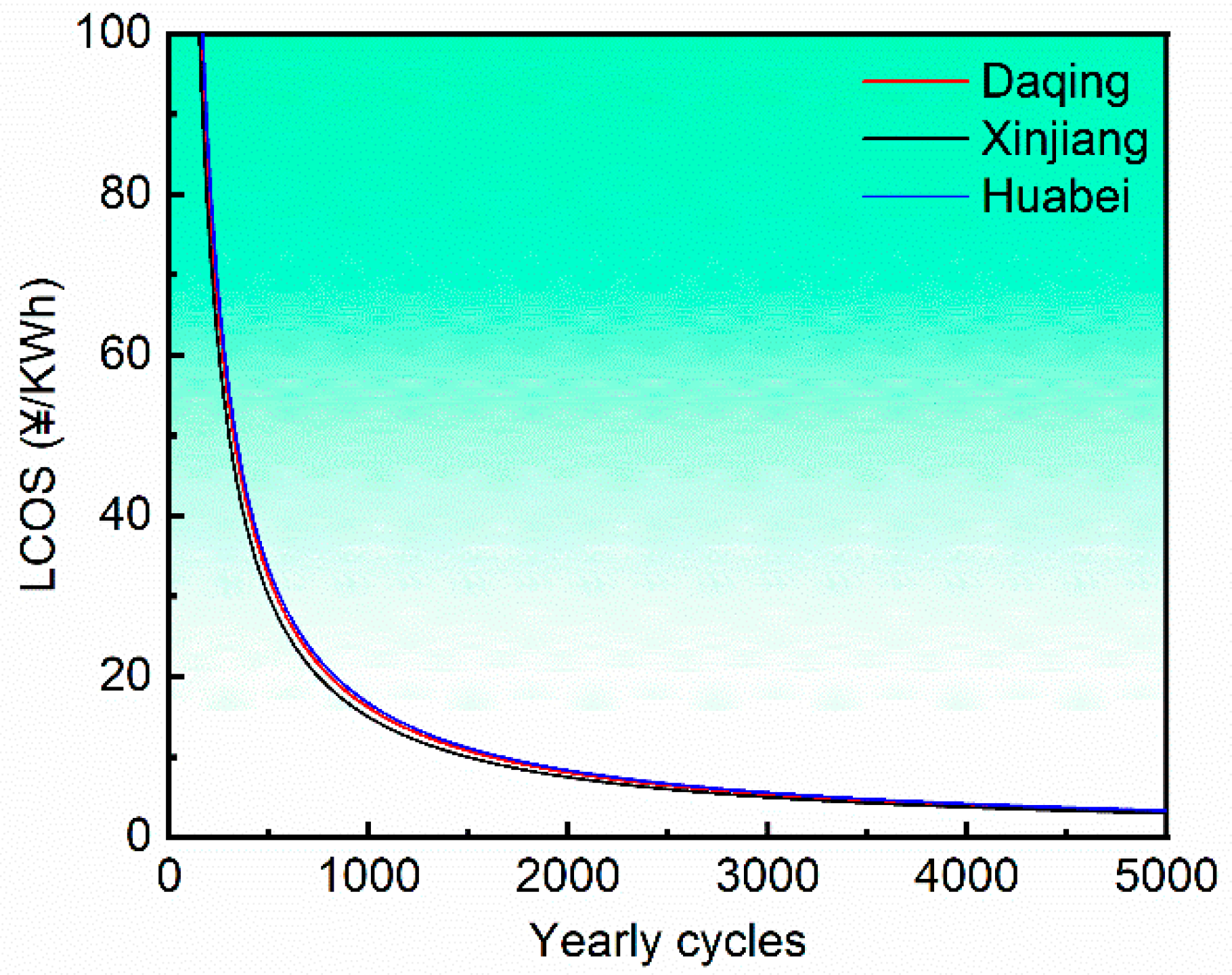
4.4. Leveling Cost of Storage of the Gravity Energy Storage System

In this study, the leveling cost of storage (LCOS) is selected as an indicator to evaluate the economic benefits of the gravity energy storage system. The LCOS provides a detailed calculation of the discounted cost per unit of energy storage. It considers all the economic and technical parameters that affect the lifetime cost of the energy storage technology. In addition, it can also be used for comparing the cost of an energy storage system with that of other storage systems with different cost structures. On the other hand, it is also an indicator that is very difficult to measure accurately because it can be affected by many factors, such as the installation and operation modes of the system and the proportions of operating and maintenance costs. To perform the theoretical research, many parameters were simplified in this case study.
In order to calculate the LCOS of the system employing Equation (15), it is necessary to determine all the parameters step by step. The CAPEX is the initial capital expenditure of the system which consists of the energy investment cost and the equipment investment cost. The excavation cost should have also been included but is ignored in this work due to the existence of ready-made abandoned wells. In addition, the energy investment cost is represented by the piston cost. In this regard, the piston costs of gravity energy storage systems in abandoned oil-gas wells in the three considered oilfields are shown in Table 8.
Furthermore, the equipment cost includes the costs of electronic and mechanical equipment. Both costs are priced per kilowatt, and the pricing method employed in this study is adopted from [33]. The cost of electronic equipment is priced at 597 CNY per kilowatt, and that of mechanical equipment is around 65 times the rated power of the system [15]. Thus, the CAPEX of the system can be obtained using this information. The annual cost of the system consists of the operational cost (COPEX), CAPEXre, power cost, and the final recovery value. The operation cost of COPEX can be regarded as a proportion of CAPEX. In this investigation, it is assumed that the COPEX is 0.5% of the initial capital expenditure. The CAPEXre is one of the important factors affecting the LCOS, and it accounts for a specific proportion (5%) of the equipment investment cost in this study case. Nevertheless, the power cost and the final recovery value are ignored in this study case. This is because the power cost varies widely at different time periods and different places, and the final recovery value of the piston material is difficult to estimate at the end of the system’s lifetime. Thus, the cost parameters of the gravity energy storage systems in the three major oilfields considered are listed in Table 9.
Other system technical information can be given in Table 10 based on information from the literature presented in previous chapters.
Thus, the variation of the LCOS with the annual cycle times of the gravity energy storage system by virtue of the abandoned wells in the three considered oilfields was calculated and presented in Figure 6.
Figure 6 clearly shows that the LCOS of the abandoned oil wells is more economically feasible under high annual cycle times. In addition, Table 11 presents the LCOS values of the gravity energy storage system by virtue of abandoned oil wells in the three major oilfields when the annual cycle times are set to 5000.
As shown in Table 11, the LCOS of the gravity energy storage system by virtue of abandoned oil-gas wells has a better economy with annual cycle times of 5000. However, it should be noted that these results were obtained assuming ideal and simplified conditions. Thus, the findings’ guiding significance for practical applications is very limited. In addition, the application of gravity energy storage systems is also very important.

5. Conclusions

The benefits and feasibility of reconstructing abandoned oil wells into gravity energy storage wells were investigated and highlighted in this paper. The main conclusions are as follows:
(1)
The power density and discharge time of gravity energy storage systems by virtue of abandoned oil-gas wells are suitable for distributed power generation.
(2)
The fast response time of gravity energy storage systems by virtue of abandoned oil-gas wells makes them suitable for correcting continuous and sudden frequency and voltage changes in the power grid. Such systems, however, are unsuitable for energy arbitrage over a large number of annual cycles.
(3)
The leveling cost of the gravity energy storage system by virtue of abandoned oil-gas wells is more economical under a high number of annual cycles.

Author Contributions

Data curation, J.W. and S.Z.; Formal analysis, J.L.; Investigation, J.W.; Methodology, J.L., Y.X. and G.S.; Software, S.Z.; Supervision, Y.X.; Writing—original draft, J.L. and J.W.; Writing—review & editing, J.L., J.W., Y.X., G.S. and Y.H.; All authors have read and agreed to the published version of the manuscript.

Funding

This research received no external funding.

Data Availability Statement

The data are available from the corresponding author upon reasonable request.

Conflicts of Interest

The authors declare no conflict of interest.

References

  1. State Council. Opinions of the Central Committee of the Communist Party of China and the State Council on the Complete and Accurate Implementation of the New Development Concept and the Good Work of Carbon Peaking and Carbon Neutrality; National Development and Reform Commission: Beijing, China, 2021. [Google Scholar]
  2. State Council. Guidance of the National Development and Reform Commission National Energy Administration on Accelerating the Development of New Energy Storage; National Development and Reform Commission: Beijing, China, 2021. [Google Scholar]
  3. DOE OE Global Energy Storage Database [DB/OL]. Available online: https://www.sandia.gov/ess-ssl/wp-content/uploads/2020/11/GESDB_Projects_11_17_2020.xlsx (accessed on 11 October 2022).
  4. Rehman, S.; Al-hadhrami, L.M.; Alam, M.M. Pumped hydro energy storage system: A technological review. Renew. Sustain. Energy Rev. 2015, 44, 586–598. [Google Scholar] [CrossRef]
  5. Yang, Z.; Xia, L.; Guan, X. Study on Renewable Energy Dispatching with Energy Storage. Smart Power 2017, 45, 25–30. [Google Scholar]
  6. Desrues, T.; Ruer, J.; Marty, P.; Fourmigue, J. A thermal energy storage process for large scale electric applications. Appl. Therm. Eng. 2010, 30, 425–432. [Google Scholar] [CrossRef]
  7. Wu, H.; Wang, J.; Gong, Y.; Yang, H.; Zhang, M.; Huang, Z. Development Status and Application Prospect Analysis of Energy Storage Technology. J. Electr. Power 2021, 36, 434–443. [Google Scholar]
  8. Tong, W.; Lu, Z.; Chen, W.; Han, M.; Zhao, G.; Wang, X.; Deng, Z. Solid gravity energy storage: A review. J. Energy Storage 2022, 53, 105226. [Google Scholar] [CrossRef]
  9. Berrada, A.; Emrani, A.; Ameur, A. Life-cycle assessment of gravity energy storage systems for large-scale application. J. Energy Storage 2021, 40, 102825. [Google Scholar] [CrossRef]
  10. Wang, S.; Xiao, L.; Tang, W.; Zhang, J.; Qiu, Q.; Guo, W.; Zhang, D. Review of new gravity energy storage. Energy Storage Sci. Technol. 2022, 11, 1575–1582. [Google Scholar]
  11. Xiao, L.; Zhang, J.; Nie, Z.; Wang, Z.; Wang, S.; Tang, W.; Yan, C.; Li, X.; Xia, X.; Qiu, Q.; et al. Underground energy storage engineering. Adv. Technol. Electr. Eng. Energy 2022, 41, 1–9. [Google Scholar]
  12. Gravitricity Renewable Energy Storage [EB/OL]. Available online: https://gravitricity.com/ (accessed on 2 October 2022).
  13. Fraenkel, P.; Wright, M. Apparatus and Method for Electrical Energy Storage. UK Patent GB2518125A, 7 June 2013. [Google Scholar]
  14. Morstyn, T.; Chilcott, M.; Mcculloch, M.D. Gravity energy storage with suspended weights for abandoned mine shafts. Appl. Energy 2019, 239, 201–206. [Google Scholar] [CrossRef]
  15. Botha, C.D.; Kamper, M.J. Capability study of dry gravity energy storage. J. Energy Storage 2019, 23, 159–174. [Google Scholar] [CrossRef]
  16. Botha, C.D.; Kamper, M.J.; Wang, R.J. Design optimisation and cost analysis of linear vernier electric machine-based gravity energy storage systems. J. Energy Storage 2021, 44, 103397. [Google Scholar] [CrossRef]
  17. Chen, Z. Environmental Damage by deserted oil and gas wells and concerning legal Liability. J. Southwest Pet. Univ. 2011, 13, 1–9. [Google Scholar]
  18. Wei, W.; Zhang, J.; Wang, H. Petroleum geothermal development and utilization model and prospect in China. China Pet. Explor. 2012, 17, 79–82. [Google Scholar]
  19. Song, X.; Xu, F.; Song, G. Technical Status and Development Suggestions in Exploiting Geothermal Energy from Abandoned Wells. Pet. Drill. Tech. 2020, 48, 1–7. [Google Scholar]
  20. Hu, X.; Lyu, J.; Zhang, X. Evaluation on application effect of direct heat exchange technology in abandoned oil wells. Geol. Resour. 2020, 29, 497–502. [Google Scholar]
  21. Zhou, X. Pilot test of transforming abandoned wells into geothermal wells in Dongpu Depression. Well Test. 2018, 27, 27–34. [Google Scholar]
  22. Li, X.; Wang, X.; Liu, Q.; Guo, X.; Wang, C.; Jia, L.; Ma, L. Successful transformation from oil exploration hole into geothermal well in Daqing area. Geol. Resour. 2021, 30, 102. [Google Scholar]
  23. Zhang, T.; Li, C.; Sun, S. Effect of Temperature on Oil-Water Separations Using Membranes in Horizontal Separators. Membranes 2022, 12, 232. [Google Scholar] [CrossRef] [PubMed]
  24. Jiang, W.; Wang, X.; Huang, H.; Zhang, D.; Ghadimi, N. Optimal economic scheduling of microgrids considering renewable energy sources based on energy hub model using demand response and improved water wave optimization algorithm. J. Energy Storage 2022, 55, 105311. [Google Scholar] [CrossRef]
  25. Jülch, V. Comparison of electricity storage options using levelized cost of storage(LCOS) method. Appl. Energy 2016, 183, 1594–1606. [Google Scholar] [CrossRef]
  26. American Petroleum Institute. Bulletinon Formulas and Calculations for Casing, Tubing, Drill Pipe and Linepipe Properties; API Bulletin 5C3–1994; API Production Department: Dallas, TX, USA, 1994. [Google Scholar]
  27. Deng, Y.; Chen, P.; Zhang, H. Calculating the pressure in sealed annulus in oil well by iterative method. Offshore Oil 2006, 26, 93–96. [Google Scholar]
  28. Du, H.; Liu, Y.; Li, X.; Xie, W. A New Method to Calculate the Heat Transfer of Wellhead of Oil and Gas Wells. China Pet. Mach. 2013, 41, 72–77. [Google Scholar]
  29. Changjiang Non-Ferrous Metals Network. [EB/OL]. Available online: https://www.ccmn.cn (accessed on 3 September 2022).
  30. Mysteel. [EB/OL]. Available online: https://www.mysteel.com (accessed on 3 September 2022).
  31. Mushiri, T.; Jirivengwa, M.; Mbohwa, C. Design of a hoisting system for a small scale mine, Procedia Manuf. Procedia Manuf. 2017, 8, 738–745. [Google Scholar] [CrossRef]
  32. Schmidt, O.; Melchior, S.; Hawkes, A. Projecting the future levelized cost of electricity storage technologies. Joule 2019, 3, 81–100. [Google Scholar] [CrossRef]
  33. McKane, A.; Hasanbeigi, A. Motor systems energy efficiency supply curves: A methodology for assessing the energy efficiency potential of industrial motor systems. Energy Policy 2011, 39, 6595–6607. [Google Scholar] [CrossRef]
Figure 1. Schematic diagram of a gravity power generation station.
Energies 16 01575 g001
Figure 2. A model of the gravity energy storage system.
Energies 16 01575 g002
Figure 3. Storage capacity of the gravitational potential energy and its variation with piston length in the three selected oilfields. (a) Storage capacity of the gravitational potential energy in the three oilfields. (b) Variation of the storage capacity of the gravitational potential energy with piston length in the three oilfields.
Energies 16 01575 g003
Figure 4. Variation of the power density with the discharge time of the gravity energy storage system in the three major oilfields.
Energies 16 01575 g004
Figure 5. Variation of the response time with the acceleration of the gravity energy storage system in the three major oilfields.
Energies 16 01575 g005
Figure 6. Variation of the LCOS with the annual cycle times of the gravity energy storage system by virtue of the abandoned wells in the three major oilfields.
Energies 16 01575 g006
Table 1. Technical parameters of common energy storage technologies [7].
Energy Storage TechnologiesRated Power (MW)Efficiency (%)Lifetime (Years)Cycle Cost ($/kWh)
Pumping energy storage100–500075–7740–600.1–1.4
Compressed air5–30052–7520–402–4
Na-S battery0.05–870–9010–158–20
Li-ion battery0–0.185–895–1515–100
Lead acid battery0–2070–905–1520–100
Flywheel energy storage0–0.25>800–153–25
Supercapacitor energy storage0–0.3<75 or >9520+2–20
Table 2. Comparison of various gravity energy storage technologies [10].
Gravity Energy Storage TechnologiesEnergy Storage ValuePowerEfficiency (%)Lifetime (Years)Response Time (s)
GPM1.6–6.4 GWh40 MW–1.6 GW75–8030+>10
HHS/GBES1–20 GWh20 MW–2.75 GW8040+>10
Undersea energy storage20 MW5–6 MW65–70>10
Energy storage tower35 MWh4 MW902.9
MGES0.5 MWh500 kW75–80Seconds level
Underground shafts1–20 MWh<40 MW80–9050+Seconds level
Table 3. Parameters of the abandoned wells in the three selected oilfields.
Oilfield WellsNumber of Abandoned WellsSpud Diameter (m)Well Depth (m)
Huabei Oilfield 95280.273150
Daqing Oilfield33,2940.273200
Xinjiang Oilfield7820.273687
Table 4. Properties of common building materials.
MaterialsDensity (kg/m3)Price (CNY2022/t)
Aluminum271218,350
Copper894062,780
Iron78503649
Lead11,34015,050
Table 5. Energy storage capacity and energy density of the three major oilfields.
Oilfield WellsMaximum Energy Storage Capacity (kWh)Energy Density (kWh/m3)
Huabei Oilfield6.191.6058
Daqing Oilfield11.002.1410
Xinjiang Oilfield129.797.3543
Table 6. Steady-state power of the three major oilfields.
Oil-Gas WellsSteady-State Power (kW)
Huabei Oilfield12.38
Daqing Oilfield22.00
Xinjiang Oilfield259.58
Table 7. Fast response time for three major oil fields.
Oil-Gas WellsResponse Time (s)
Huabei Oilfield0.085
Daqing Oilfield0.064
Xinjiang Oilfield0.019
Table 8. Piston costs of gravity energy storage systems in abandoned oil-gas wells in the three considered oilfields.
Abandoned WellsPiston Mass (t)Piston Cost (CNY)
Huabei Oilfield29.583107,948.367
Daqing Oilfield39.444143,931.156
Xinjiang Oilfield135.490494,403.010
Table 9. Cost parameters of the gravity energy storage systems in the three major oilfields.
Abandoned WellsCAPEX (CNY)COPEX (CNY)CAPEXre (CNY)
Huabei Oilfield596,353.0352981.76524,420.233
Daqing Oilfield1,011,855.4445059.27743,396.214
Xinjiang Oilfield10,735,120.58753,675.603512,035.879
Table 10. Attribute examples of the gravity energy storage system.
AttributeValue
Discharge time30 min
Depth of discharge1
Efficiency η85%
Discount rate10%
System lifetime50 years
Table 11. LCOS values of the gravity energy storage system by virtue of abandoned oil wells in the three major oilfields with annual cycle times of 5000.
Abandoned WellsLCOS (CNY/kWh)
Huabei Oilfield3.3279
Daqing Oilfield3.2195
Xinjiang Oilfield2.9884
Disclaimer/Publisher’s Note: The statements, opinions and data contained in all publications are solely those of the individual author(s) and contributor(s) and not of MDPI and/or the editor(s). MDPI and/or the editor(s) disclaim responsibility for any injury to people or property resulting from any ideas, methods, instructions or products referred to in the content.

