
Model of an Air Transformer for Analyses of Wireless Power Transfer Systems


Department of Marine Electronics, Gdynia Maritime University, 81-225 Gdynia, Poland
*
Author to whom correspondence should be addressed.
Energies 2023, 16(3), 1391; https://doi.org/10.3390/en16031391
Submission received: 30 December 2022
/
Revised: 24 January 2023
/
Accepted: 27 January 2023
/
Published: 30 January 2023
(This article belongs to the Special Issue Advances in Power System Analysis and Control)
Abstract
:This article presents a new model of a dedicated air transformer for computer analyses of wireless power transfer systems. This model includes a form of subcircuit for SPICE. It takes into account the electric, magnetic and thermal properties of the modeled device. The form of the elaborated model is presented and the results of its experimental verification are shown. Some results from measurements and computations of an air transformer and a wireless power transfer system containing this transformer are shown and discussed. The structure of the tested system and the measuring setup used are also described. The results of measurements and computations illustrating the influence of the distance between the windings of the air transformer and the displacement between its windings on the output voltage of the power transfer system are presented and discussed. The influence of load resistance on the properties of the considered system is analyzed.
1. Introduction
Wireless power transfer (WPT) technology has been known for years; the pioneer in this field was Nicola Tesla, who in 1891 designed a coil that could transmit power wirelessly over a distance of 3 km [1,2]. However, wider interest in the transmission of power over a distance without the use of traditional cables appeared only in 2007, when a group of scientists from the Massachusetts Institute of Technology (MIT) designed a WPT system that allowed the power transfer to light a 60 W bulb at a 2 m distance [1,3].
Recently, there has been an increase in interest in new technologies, i.e., various types of portable devices used in various industries. There can be devices of general use (tablets, laptops, mobile phones) or devices used in medicine (implantology), mining (sensors, headlamps) or the automotive industry [4,5,6,7,8]. However, the problem of these devices is their power supply [8,9]. For example, mobile phones, tablets or laptops can typically operate for several dozen hours without recharging [4,8,10]. This usage time is a function of many factors, such as the capacity of the battery, how the device is equipped, the operating time of the device, etc. It is therefore important to ensure that devices can be charged without the need for a classic corded power supply, especially in mining or medical applications [5,8,11].
Wireless power transfer systems occupy more and more space in the literature [5,8,11,12,13]. These systems differ in terms of their manufacturing technology depending on the application and the distance over which the power is to be transferred [4,6,14,15]. However, from the point of view of consumer devices or devices used in medicine, mining or the automotive industry, IPT (induction power transfer) technology is typically used for wireless power transfer. The concept of this technology is based on the principle of an air transformer and is described in more detail in [8,16].
As shown in [8,17], IPT technology is characterized by the highest efficiency of power transfer compared with other technologies, reaching up to 90% [8,17]. Additionally, papers [18,19,20] demonstrate that the properties of an IPT system, including its efficiency of power transfer, are influenced by many factors, e.g., the mutual positions of the transmitter and the receiver, the shape of the air transformer coils and the type of the core used. For example, in [18] it was shown that changing the vertical distance between the coils from 15 mm to 160 mm causes a threefold decrease in the coupling coefficient.
On the other hand, a change in the horizontal distance between the transmitter and the receiver by about 200 mm causes a decrease in the value of the considered factor by 60%. In [19] it was noted that the use of pentagonal-shaped coils with a surface area of approx. 110 mm2 can obtain an efficiency of power transfer of approx. 80% with a distance between the transmitting and receiving coils of 10 mm. The use of oval or rectangular-shaped coils with a surface area similar to pentagonal ones obtained an efficiency of power transfer 30% lower than for pentagonal coils. In [20] it was pointed out that output power increases with an increase of the goodness of fit of Q. An increase in the value of this factor from 20 to 110 causes over a threefold increase in the transmitted power. It was also shown that an increase in Q from 20 to 110 causes a decrease in the efficiency of power transfer by approx. 10%.
It was noted in [21] that the type of material used to build the transformer’s ferromagnetic core affects wireless power transfer system properties. The influence of frequency on the efficiency of the system was considered. Tests were carried out for systems containing four different ferromagnetic cores, i.e., iron dust, NiZn, Sendust and ferrite. On the basis of the test results, it was shown that frequency does not significantly affect the efficiency of power transfer with the use of iron dust. However, the use of this material resulted in reaching a value of the considered parameter up to 10 times lower than for ferrite and 4 times lower than for NiZn for higher frequency values. The highest efficiency was observed for ferrite. An increase in frequency from 10 to 140 kHz caused up to a twofold increase in the efficiency of power transfer by using a core made of ferrite material.
The aim of this article is to model the characteristics of an air transformer using SPICE and to perform computer analysis of the properties of a WPT system with the use of this model. The proposed model belongs to the group of compact electrothermal models that takes into account both electrical and thermal phenomena occurring in an air transformer. The form of the model is presented and some results of its experimental verification are shown. This verification was performed for two cases: for a transformer with a resistance load and for a transformer operating in a WPT system.
2. Literature Review
According to the literature, air transformers are characterized by limited application possibilities due to their lack of a ferromagnetic core that would permit concentrating the magnetic flux and obtaining high and controlled values of the coupling coefficient between the coils of such a transformer [22]. Thus, they are most often used as magnetic field sensors [22] or in medicine for scanning and imaging possible changes in the human body (magnetic resonance) [22,23].
Recently, air transformers have also been used in systems for wireless power transfer [22]. More and more papers devoted to models of this type of system appear in the literature [22]. For example, in [22] a method of determining the coefficient of mutual inductance of such a transformer is presented. Analytical relationships used to determine this parameter for an air transformer containing toroidal coils with a circular cross-section and an air transformer with any coil cross-sectional shape are presented. The calculations presented in the cited paper using the proposed relationships show that if both windings of the transformer are arranged in the same axis, the mutual inductance coefficient does not depend on the density of the turns of both windings. Attention is also paid to the fact that the biggest differences in the values of this coefficient are obtained in places where there are no transformer windings in the same axis and there is an evident current associated with the leakage flux.
On the other hand, in [23] a basic model of a system for wireless power transfer is presented. The simplified network representation of the model presented in this paper includes an inverter and a rectifier represented by voltage sources. Instead of an air transformer, a T-type transformer model known from the literature is used. In this model, its leakage inductance and magnetizing inductance are introduced. Resistors representing power losses in both the windings related to the resistance of the winding wire, increased due to skin and proximity effects, are also used. The authors performed calculations using the proposed model and compared them with the results of their measurements. From the presented results it can be seen that the use of the simplified model, which also assumes sinusoidal coil currents, enables the optimal selection of PTO system parameters in terms of energy efficiency. However, the distortion of the currents becomes more pronounced as the magnetic coupling coefficient increases.
The authors of [24] presented analytical considerations regarding the use of an air transformer with low power consumption used in high-voltage power transfer systems (HVDC). Relationships for calculating self-inductance and mutual inductance of an air transformer operating in the mentioned systems are proposed. In order to verify the proposed dependences, a prototype of such a transformer was built. Calculations made using this model proved that very good results are obtained as far as determining the air transformer parameters are concerned, including its self- and mutual inductances.
In [25], a system for wireless power transfer based on a model of an ideal transformer with magnetic coupling (IT MC-WPT) was considered. In the proposed system, simplifications were assumed consisting in the assumption that the amplitudes of the primary and secondary winding currents are constant and do not depend on mutual inductance. Thanks to this, the proposed system is suitable for both low voltage–high current and high voltage–low current operation, and the ratio of the amplitude of the secondary winding current to the primary winding current can be adjusted depending on the application. The proposed solution is characterized by high power transfer efficiency. This paper presents theoretical considerations, analytical dependences and principles of designing systems for wireless power transfer with air transformers. It demonstrates theoretically and experimentally that an IT MC-WPT system can achieve a high and constant value of transmitted energy and efficiency with changes in the coupling coefficient between the transformer coils.
In [26], an air transformer design procedure is discussed. This procedure boils down to a combination of analytical methods and finite element analysis to calculate the parameters of the transformer. It is pointed out that analytical methods are used to calculate parameters and to design the appropriate windings of various dimensions and number of turns. How to determine the coupling coefficient for each transformer using these methods is also demonstrated. In turn, after determining the abovementioned parameters using the appropriate programs for finite element analysis, the characteristics corresponding to the magnetic properties of the transformer are obtained, which can then be used in a commercial program for the analysis of electric circuits. Calculations were carried out in accordance with the procedure presented in the paper. Tests were carried out for air transformers containing oval coils with a different number of turns and different external and internal diameters. From the results presented, it can be observed that up to a frequency of 1 MHz the resistance of the coil windings and their inductance do not depend on frequency but only on the number of turns. Above this frequency, resistance significantly increases and inductance decreases.
Paper [27] presents a heuristic approach to the design of WPT systems. Tests were carried out for rectangular transmitting and receiving coils. The focus was on an analysis of the efficiency of power transfer as a function of the coupling coefficient between the coils. Analysis was carried out using Maxwell software, which allows the simulation to be performed using the finite element method (FEM). Using this method, the influence of the thickness and size of the air transformer coils and the displacement between the coils on the distribution of the magnetic field between them as well as the product of the coupling factor and the quality of the coils were analyzed.
The authors of [28] point out that the magnetic coupling between the transmitting and receiving coils is the most important parameter of WPT systems. A method of designing an air transformer to maximize its efficiency, power density, power transfer distance and misalignment tolerance while minimizing the leakage field, weight, cost and volume using FEM is discussed. The influence of the power electronic system, industrial standards, selection of materials, numerical and analytical modeling methods and thermal modeling on the coil design process was determined. In addition, an example of a transformer coil design based on FEM tools is presented.
In paper [29], attention was drawn to the problem of the presence of a leakage field in an air transformer. The use of FEM was proposed to analyze the influence of the air transformer shape on its coupling coefficient in order to minimize this leakage field. Maxwell software was used for the analysis. An air transformer was designed based on the simulation results, with a coupling coefficient comparable to that of a toroidal transformer.
Paper [30] discusses the problem of eddy currents and a leakage field in WPT systems located in an autonomous underwater vehicle. It is pointed out that the existence of a ferrite core causes nonlinear distortion of the magnetic field; this complicates and hinders the construction of an air transformer in the system under consideration, which will be characterized by a sufficiently large coupling factor. This paper presents a method for designing a transformer for WPT systems and determining its parameters using FEM.
In [31], the influence of the skin effect occurring in the copper wire (from which the coils of an air transformer are made) on its properties was investigated. The considerations concern transformers used in high-frequency resonant WPT systems. Tests were carried out on a hollow copper wire. The changes in AC resistance of this wire were analyzed using FEM as a specific case study of the WPT system. In this paper, an empirical formula was proposed that allows the use of such a wire while ensuring the appropriate current density at a sufficiently high frequency.
The author of [32] presented the results of a computer analysis of a WPT system with two flat coils of round and square shapes. The influence of the shape of the coils, the number of turns and the distance between the coils on the efficiency of the WPT system was compared. The tests were carried out in a wide range of frequencies from 100 kHz to 1 MHz. FEM and antiperiodic boundary conditions were used for the analysis. The highest power transfer efficiency value was obtained for the WPT system containing square coils, while at higher frequencies higher efficiency values were obtained with the use of round coils.
From the literature review presented above, it can be seen that most of the papers cited are devoted to methods of designing air transformers. Many of the papers describe the results obtained using FEM, which needs time-consuming computations. The use of FEM makes it possible to obtain space–time distribution of temperature, current density or the magnetic field, taking into account selected physical phenomena. Selection of the important phenomena and formulation of the proper set of differential-algebraic equations is difficult and indispensable computations are time-consuming. On the other hand, compact models make it possible to characterize electrical, magnetic or thermal properties of the modeled devices using simple equations and they can be experimentally verified using simple measurements. Some papers describing compact models of such transformers take into account only the electrical properties of the devices. These models do not take into account thermal phenomena. Therefore, in the next section a new model of such transformers is proposed. This model takes into account electrical and thermal phenomena occurring in the transformer.
3. Model Form
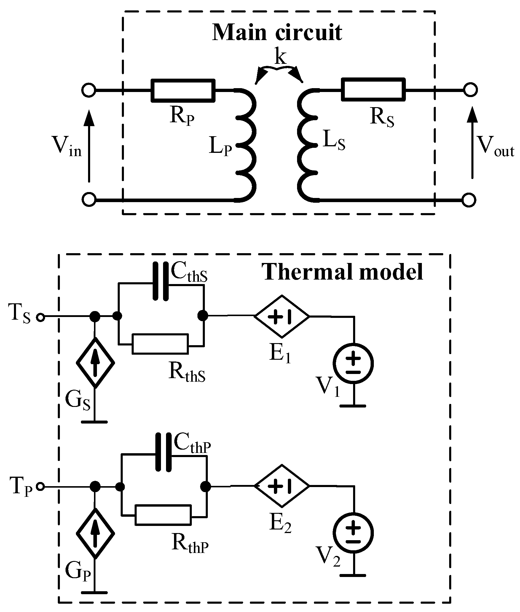
A model of an air transformer was formulated in the network form shown in Figure 1. This model is dedicated to the SPICE program. The model takes into account the linear magnetic coupling between the windings and the parasitic inductances and resistances of the windings, the values of which depend on frequency, and this dependence was described using quadratic functions. Additionally, in this model the self-heating phenomenon in both the windings and mutual thermal couplings between these windings were taken into account. Parameter k, characterizing magnetic coupling between both the windings, depends on the distance between these windings measured in x and y directions.
Two blocks can be distinguished in the presented model. The main circuit describes electrical properties of the modeled transformer, while the thermal model enables the calculation of the temperature of each winding at the steady state.
In the main circuit, inductors LS and LP represent the inductances of the secondary and primary windings, respectively, and resistors RS and RP represent the resistances of these windings. All the components included in this circuit are linear and their values depend on frequency f by means of an increasing quadratic function. The dependences describing the inductances and resistances of frequency f have the same forms, which for inductor Lp is as follows:
where a, b and c are the model parameters.
The LP and LS inductors are linearly coupled, and the coupling coefficient k is described by the formula
where dy is the distance between the windings of an air transformer located in the same Y axis, dx is the distance in the X direction between the centers of the windings and MIN(x,y) is a standard function of the SPICE program that assumes the value of the smaller of its arguments x and y. The parameters of the function are the coefficients, k1, k2, k3, k4, k5, k6 and k7.
When implementing an electrical model in SPICE, the built-in models of inductors, resistors and magnetic couplings are used. The parameters of these components are described with the formulas given in Equations (1) and (2).
The thermal model makes it possible to determine the temperature values of the secondary winding TS and the primary winding TP at the steady state, taking into account the self-heating phenomenon in each winding and mutual thermal couplings between these windings. In this model, as in the models described in [33,34], the current sources GP and GS represent the power lost in the primary windings pp and the secondary windings ps, respectively. Each of these powers is described by the formula
where m has the value p for the primary winding and s for the secondary winding, VRm is voltage across resistor Rm and im is the current flowing through this resistor.
The Rthp and Rths resistors represent the thermal resistances of the primary and secondary windings respectively, while Cthp and Cths capacitors represent the thermal capacitances of these windings. Due to the fact that this model is dedicated to determining the temperature of the windings at the steady state, the values of these capacitances assume values that ensure the fulfillment of the condition
Voltage sources V1 and V2 model the ambient temperature. The controlled voltage sources E1 and E2 model mutual thermal couplings between the windings. The output voltage of source E1 is given by the formula
where Rthm is the mutual thermal resistance between the windings. The output voltage of the E2 source is given by an analogous formula, whereby voltage Vthp should be replaced with voltage Vths and thermal resistance Rthp with thermal resistance Rths. The Rthm value is a decreasing function of the distances between the windings dy and dx described by the formula
where Rthm1, αT and αT1 are the model parameters.
The model of an air transformer proposed above is dedicated to transient analysis. Due to simplifications assumed in formulating this thermal model, the proper waveforms of currents and voltages should be taken into account only at the thermally steady state, when the temperature waveforms of both the windings are periodical.
4. Investigated Devices
Investigations were performed for the air transformer described in Section 4.1 and the system for wireless power transfer described in Section 4.2.
4.1. Air Transformer
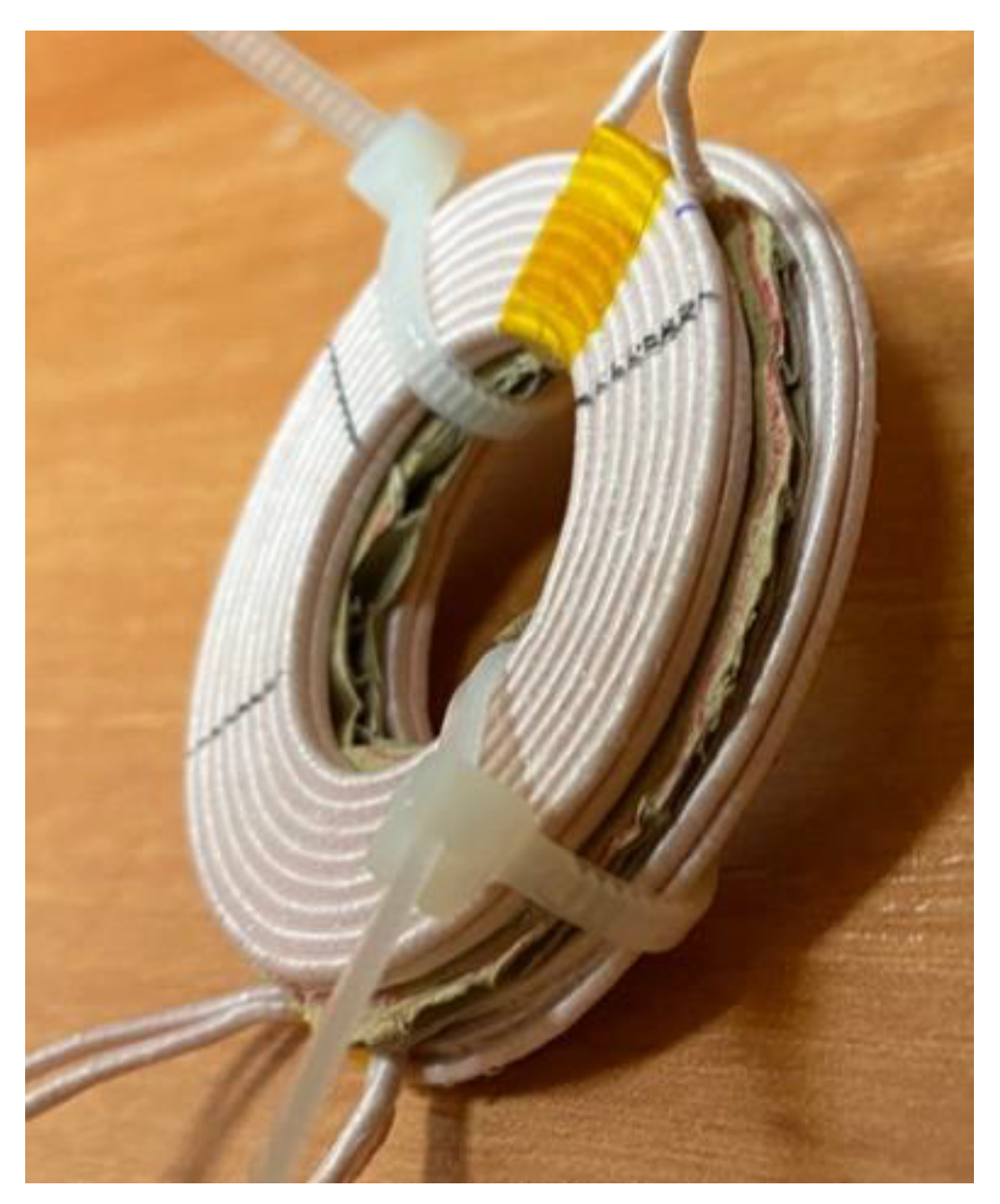
Figure 2 shows the tested air transformer.
The primary and secondary windings of the air transformer shown in Figure 2 are made of two superimposed windings. The primary winding consists of two layers of 10 turns each made of litz wire with a diameter of 1 mm. The secondary winding consists of 2 × 8 coils made of the same litz wire. The receiver coil inductance is approximately 3.7 µH and the transmitting coil inductance is 14 µH. The outer diameter of the receiving coil is 40 mm and the transmitting coil 42 mm.
For this transformer, values of the model parameters described in the previous section were determined on the basis of measurements of its characteristics. The values of the parameters occurring in the relationships describing the components of the main circuit of this model are summarized in Table 1.
Parameters describing the coupling coefficient k have the following values: k1 = 0.638, k2 = 0.2 mm, k3 = 9 mm, k4 = 0.638, k5 = 4.7 × 10² m−2, k6 = −41 m−1 and k7 = 0.9756. In turn, parameters occurring in the thermal model have the same values equal to Rths = Rthp = 22.2 K/W. Values of the parameters describing the dependence Rthm(dy, dx) are as follows: Rthm1 = 13.16 K/W, αT = 11 mm and αT1 = 0.016/mm.
4.2. System for Wireless Power Transfer
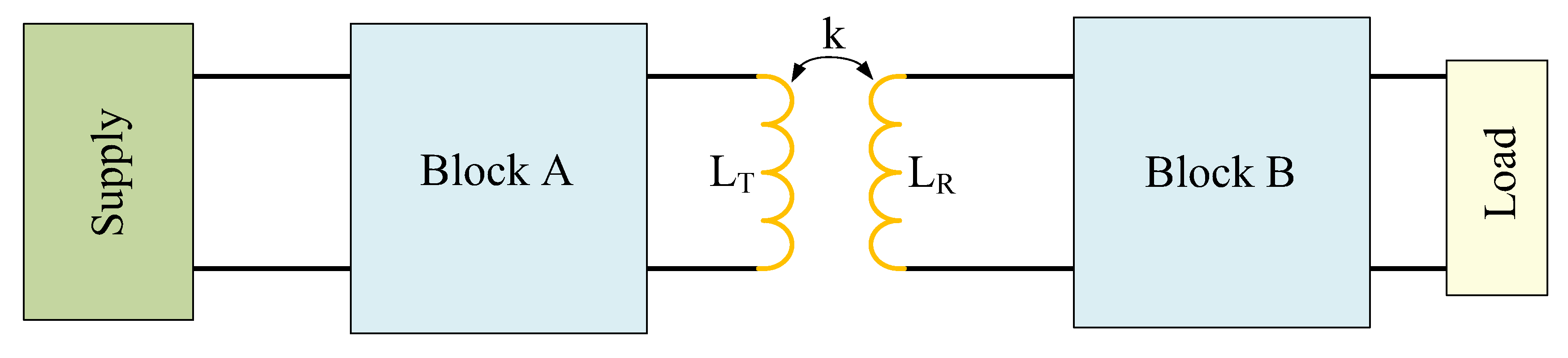
The system used for wireless power transfer is shown in Figure 3.
In order to investigate the influence of the air transformer’s properties on the wireless power transfer system characteristics, a commercially available integrated circuit SKU 106990017 from Seeed Technology [35] was used. Apart from the blocks containing the power conversion systems, this system includes an air transformer, in which the primary winding acts as a transmitting coil and the secondary winding acts as a receiving coil.
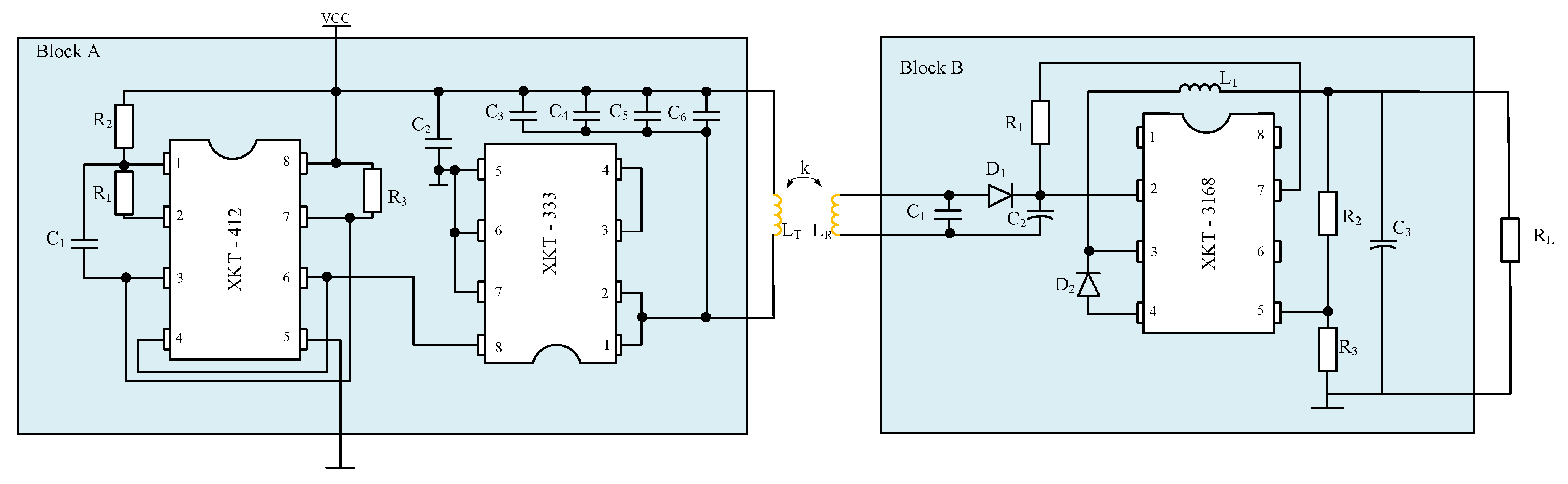
The block diagram of the system for wireless power transfer on the transmitter presented in Figure 3 consists of a power source, block A, which includes a DC–DC converter and a high-frequency generator (XKT-412), a power amplifier (XKT-333) and a transmitting coil. On the receiver side, the circuit consists of a receiving coil, block B, which contains a rectifier, a voltage stabilizer and a load. Schematic diagrams of the systems representing blocks A and B are presented in Figure 4.
In the system shown in Figure 4, apart from the magnetic components mentioned above on the transmitter and the receiver side, there are also block A and block B.
The XKT-412 integrated circuit in block A is a chip used in high-frequency applications up to 2 MHz. It is used to regulate the supply voltage within a range from 5 to 12 V and supplies the XKT-333 system. The XKT-412 system acts as a DC–DC converter and a generator that produces a signal with a frequency of 70 kHz at the output. In turn, the XKT-333 integrated circuit is a power amplifier used to generate periodic signals with a frequency of about 150 kHz. LT, C3, C4, C5 and C6 components act as the output oscillator and set the frequency of the transmitted signal to about 110 kHz. In order to ensure the proper functioning of the integrated circuits contained in block A, it was necessary to use the appropriate passive components, the values of which are summarized in Table 2.
In turn, block B contains the XKT-3168 integrated circuit, with discrete components acting as an output switch-mode voltage stabilizer, an electro-magnetic wave (LR) receiver, a half-wave rectifier with a filter (D1, C1, C2 and R1) and a divider voltage matching the output voltage to 5V (R2, R3). Component L1 is used as an inductor in the buck DC–DC converter controlled by XKT-3168. Capacitor C3 plays the role of the output filter, while D2 is the diode in the buck converter. Diode D1 plays the role of the rectifier. The values of the passive components included in block B are given in Table 3. The values of components visible in Figure 4 are given in [36] and collected in Table 2 and Table 3.
Table 4 shows the manufacturer’s declared parameters of the considered system for wireless power transfer.
As can be seen in Table 4, the manufacturer declares the correct operation of the system when the distance between the receiver and the transmitter is lower than 10 mm. Additionally, it is observed that the possible output voltage is 5 V, with an output current up to 1.2 A.
5. Measurement Setups
In order to investigate the influence of the properties of the air transformer on the characteristics of the selected system for wireless power transfer, two measurement systems were used. The first one was used to test the properties of the air transformer (Section 5.1). However, in order to investigate the influence of the properties of the transformer on the characteristics of the WPT system discussed in Section 4, the measuring system discussed in Section 5.2 was used.
5.1. Measurement of the Air Transformer’s Parameters
To test the properties of the air transformer described in Section 4, the measuring system shown in Figure 5 was used.
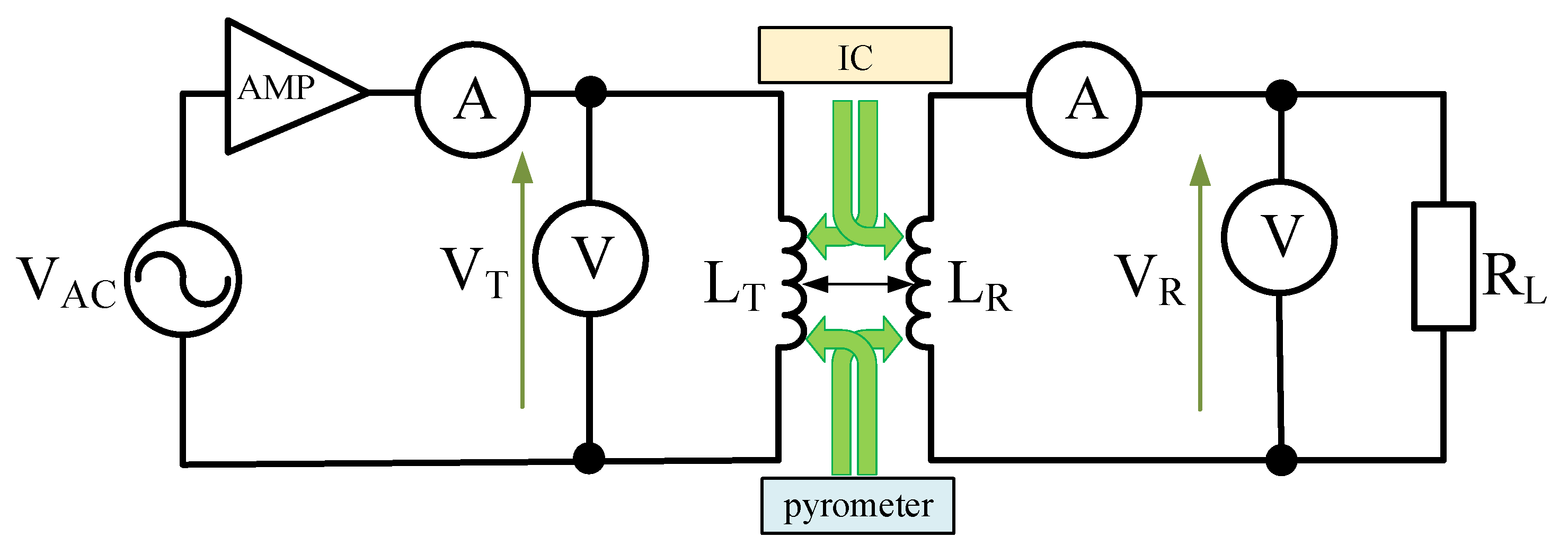
The circuit shown in Figure 5 consists of an RIGOL function generator producing a VAC harmonic signal of frequency f, which is amplified by the AETECHRON 7228 signal amplifier (AMP) [37]. RIGOL DM3068 digital multimeters were used to measure the RMS values of current and voltage on the transmitting and receiving coil side. Additionally, the temperature of the transmitting and receiving coils were recorded using an FLIR i5 [38] thermal imaging camera (IC) and a PT-3S [39] pyrometer.
5.2. Measurement of WPT System Parameters
In order to test the properties of the WPT system described in Section 2, the measuring setup shown in Figure 6 was used.
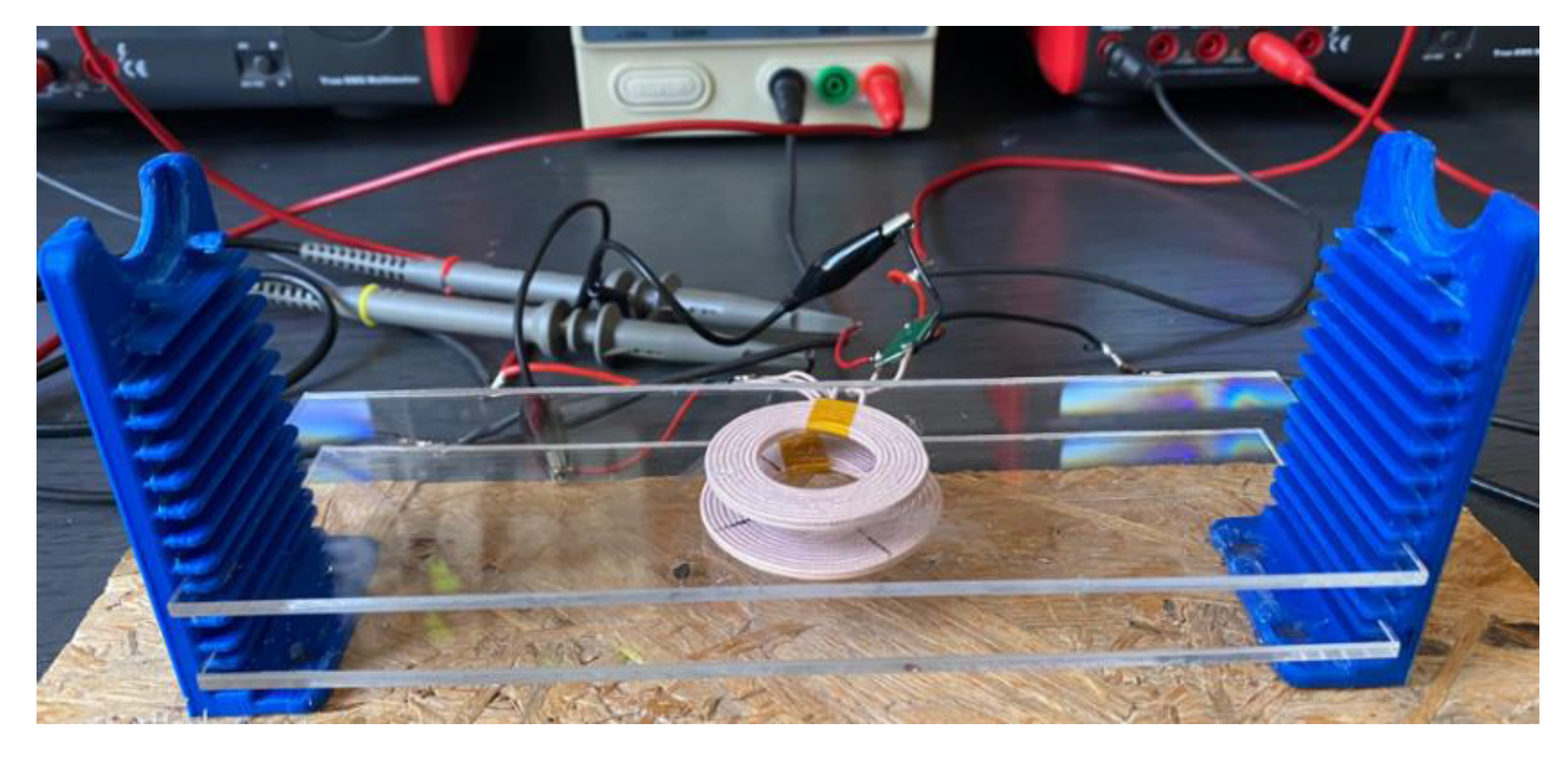
This setup consists of a transmitter circuit powered by a VDC voltage source and a receiver circuit loaded with an RL resistor. Blocks A and B are described in Section 4. To record the RMS values of currents and voltages in the transmitter and receiver circuits, UNIT UT-803 digital multimeters were used. In order to change the position of the transmitter and receiver coils vertically (in relation to the Y axis) and horizontally (in relation to the X axis), the stand shown in Figure 7 was made using a 3D printer and two washers made of acrylic, to which the transmitter and the receiver were attached.
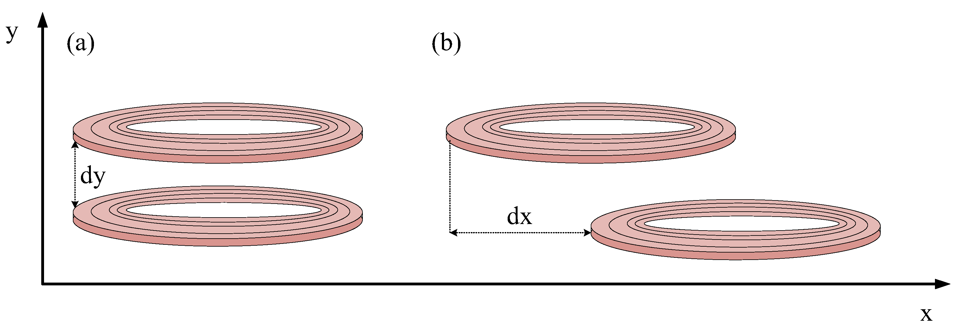
Figure 8 presents the principle adopted for changing the position between the coils of the considered system. Changing the vertical position means a change in the distance dy in the direction of the Y axis between the transmitting coil and the receiving coil (dx = 0) (Figure 8a). On the other hand, a change in the horizontal position means a change in the distance dx between these coils at a constant dy value (Figure 8b).
6. Investigation Results
The usefulness of any model can be verified by comparing the results obtained from computations with the results of measurements or with the results of computations obtained using some other well-known method. Instead of an analysis using the classical finite element method [31,32], verification of the proposed model was performed using the results of measurements.
This section presents the results of the research on properties of the air transformer and the commercial WPT system. The test results illustrating the properties of the air transformer are presented in Section 6.1. The results of our research on the influence of the air transformer properties on the WPT system are presented in Section 6.2.
6.1. Investigation of Properties of an Air Transformer
Using the measuring setup shown in Figure 6, the influence of selected factors such as load resistance and frequency of the exciting signal on the voltage on the primary and secondary windings of the air transformer and its voltage ratio was investigated. The temperatures of both transformer windings were also recorded using a thermal imaging camera and pyrometer. Additionally, with the use of an RLC bridge by GwInstek [40] generating a sinusoidal signal with a peak-to-peak value of 1 V, inductance and resistance of the transmitting and receiving coils were tested in a wide range of excitation signal frequency changes from 20 Hz to 10 MHz. In all figures presented in this section, points denote the results of measurements, whereas lines show the results of computations performed using the model described in Section 3.
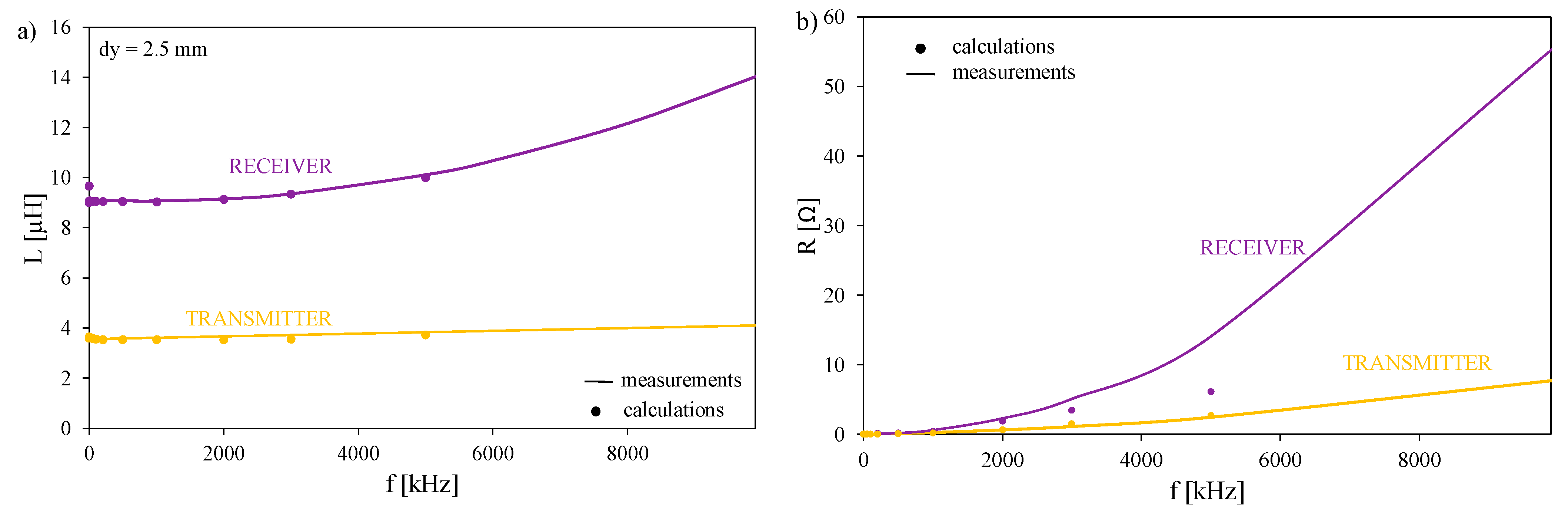
Figure 9 shows the dependences of inductance and series resistance of the transmitting coil and the transformer receiving coil on frequency, measured by means of the RLC bridge. The distance dy between the transmitting and receiving coils is 2.5 mm.
As can be seen, both the inductance and series resistance of both windings are significantly different from each other. In the frequency range f < 5 MHz, the inductance values of the transmitter and the receiver are practically constant. The observed differences between the inductances of the transmitter and the receiver result from the different number of turns contained in these windings. At the highest frequency value under consideration, an almost twofold increase in the transmitter inductance is visible. The series resistance of the inductor increases with increasing frequency and becomes much higher than the measured DC winding resistance. A good agreement between the results of measurements and calculations confirm the correctness of the proposed equations L(f) and R(f).
Figure 10 illustrates the influence of distances dx and dy between both the coils on mutual thermal resistance between these coils Rthm.
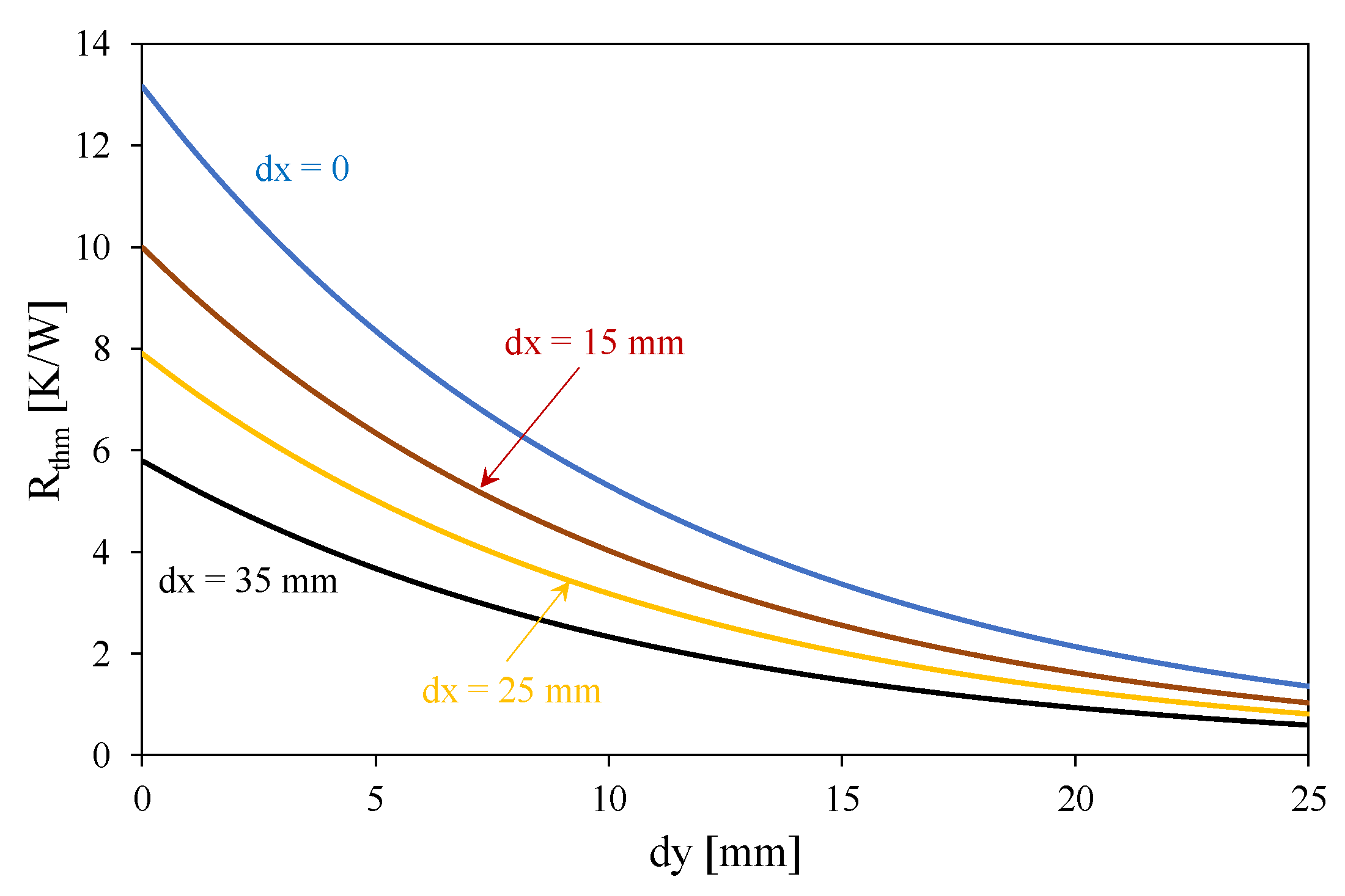
As can be seen, mutual thermal resistance between the coils is a decreasing function of distances dx and dy. When distance dy reaches 20 mm, the value of Rthm does not exceed 10% of the value of this parameter obtained at dy = 0. The influence of distance dx is weaker than the influence of dy on Rthm. At dx = 35 mm, the value of Rthm is lower than 50% of the value of this parameter at dx = 0.
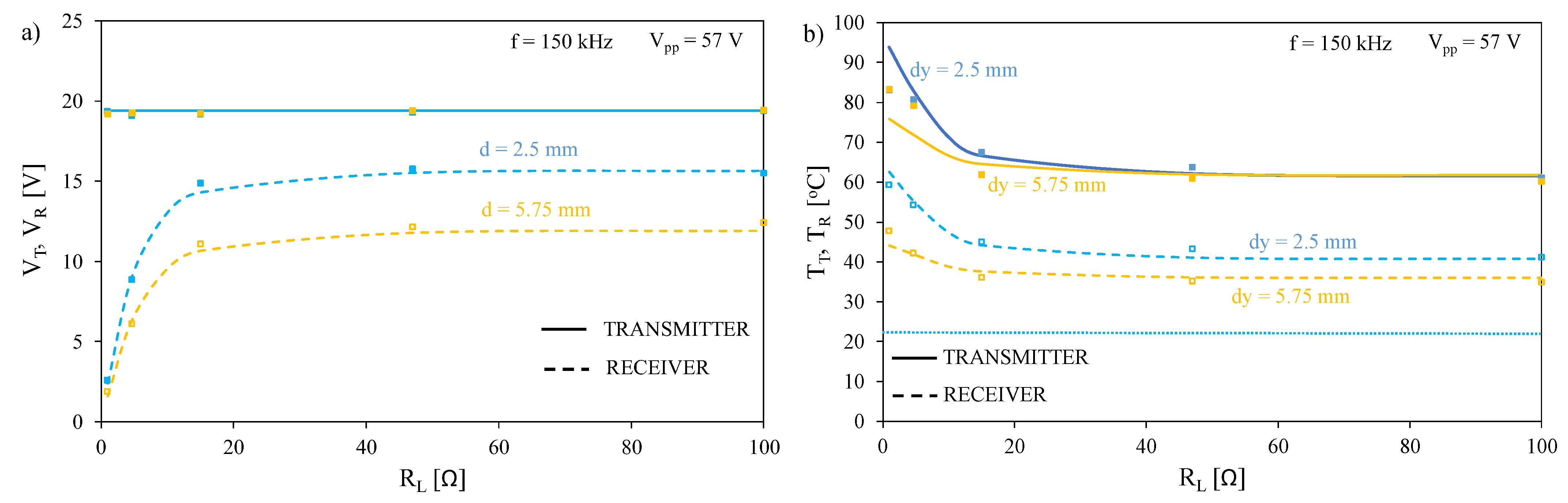
Figure 11 illustrates the influence of load resistance on voltage across both windings of the transformer and the temperature of these windings at selected values of distance dy between these windings. The tests were carried out at frequency f = 150 kHz and the peak-to-peak value of the supply voltage Vinpp = 57 V.
As can be seen in Figure 11a, at a fixed voltage value at the transmitter, the dependence VR(RL) is an increasing function, and an increase in the distance between the coils causes a decrease in voltage VR. Changing the dy value from 2.5 to 5.75 mm causes a drop in VR voltage by as much as 25%. In turn, Figure 11b shows that the temperatures of both the windings are a decreasing function of resistance RL. The temperature of the transmitter winding is up to 20 °C higher than the temperature of the receiver, which is related to differences in the series resistance values of these windings. An increase in the distance between the windings causes an increase in the difference between the temperatures of the windings due to the weakening of mutual thermal couplings between them. It is worth noticing that using classical models (dotted lines) omitting thermal phenomena, the temperatures of both the coils is equal to the ambient temperature at each considered value of the distance dy.
Figure 12 illustrates the influence of frequency on the dependence of the voltage of the receiver VR on load resistance. Tests were carried out with the distance between the coils dy = 2.5 mm and the peak-to-peak value of the supply voltage Vinpp = 10 V.
As can be seen, the dependence VR(RL) is a monotonically increasing function for each of the considered frequency values. An increase in the frequency value causes a decrease in the slope of the considered characteristic. At the highest of the considered RL values, the influence of frequency on VR voltage is practically unnoticeable.
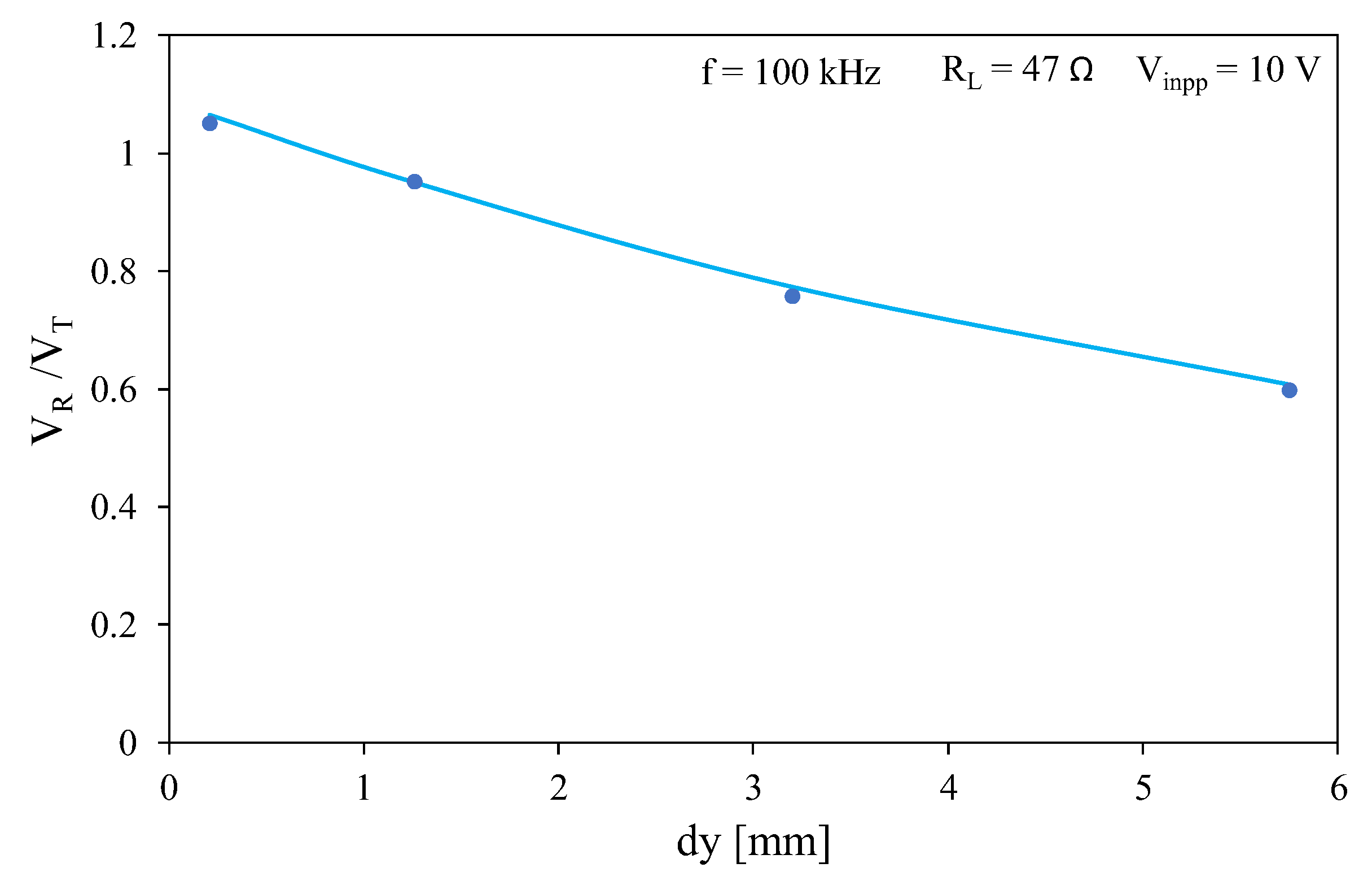
Figure 13 illustrates the dependence of the transformer turns ratio on the distance between the coils. The tests were carried out at f = 100 kHz and Vinpp = 10 V.
As can be seen, a monotonically decreasing relationship is obtained. It is worth noting that an increase in the distance between the coils from 0.21 mm to 5.75 mm causes a decrease in the value of the turns ratio by more than 40%.
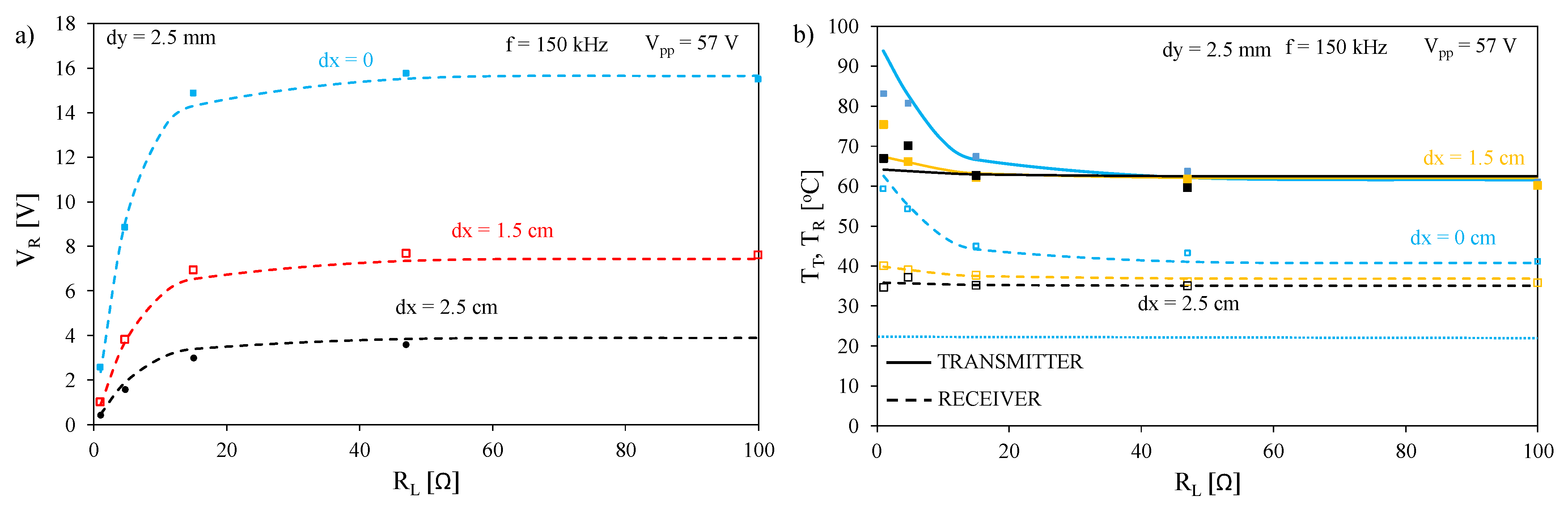
Figure 14 illustrates the influence of the shift dx between the axes of the coils in the direction of the X axis on the output voltage of the transformer (Figure 14a) and on the temperatures of the windings (Figure 14b). The tests were carried out with a distance between the coils dy = 2.5 mm, a peak-to-peak value of the supply voltage Vinpp = 57 V and frequency f = 150 kHz.
As can be seen in Figure 14a, an increase in the distance in the direction of the horizontal axis between the axes of the coils causes a significant decrease in the voltage on the secondary winding of the transformer. Changing the dx distance from 0 to 2.5 cm results in a fivefold decrease in VR voltage. In turn, Figure 14b shows that an increase in distance dx results in a decrease in temperature TR, with the greatest changes in this temperature being visible for low values of load resistance RL. These changes exceed 25 °C at RL = 1 Ω. For RL values above 20 Ω, a change in the dx value from 0 to 2.5 cm causes a change in temperature TR reaching 10 °C. As can be seen, using classical models (dotted lines) omitting thermal phenomena, the temperatures of both coils are equal to the ambient temperature at each considered value of distance dx.
In order to verify the legitimacy of using the compact thermal model of the air transformer, measurements of the temperature distribution on the surface of the tested transformer were carried out. The temperature distribution on the surface of the primary winding of the transformer at resistance RL = 4.7 Ω and the frequency of the exciting signal is shown in Figure 15.
As can be seen, the temperature on the surface of the tested winding has an almost even distribution for the middle turns of this winding. The temperature at the edges of the winding is up to 10 °C lower than for the middle turns. The areas of lower temperature in the axis of the transformer diameter correspond to the location of the tapes mounting the turns of this winding. These are characterized by a lower value of emissivity than the windings.
6.2. Investigation of the WPT System
Using the measuring system presented in Figure 6 and described in Section 5, the influence of the position of the transmitting and receiving coils and of load resistance on parameters of the tested WPT system were investigated.
In computer analyses of the WPT, block A was modeled using a voltage generator with series resistance. Block B was modeled using a rectifier loaded by an integrating circuit and a controlled voltage source with a series resistance. In all further considerations, the supply voltage was 5 V.
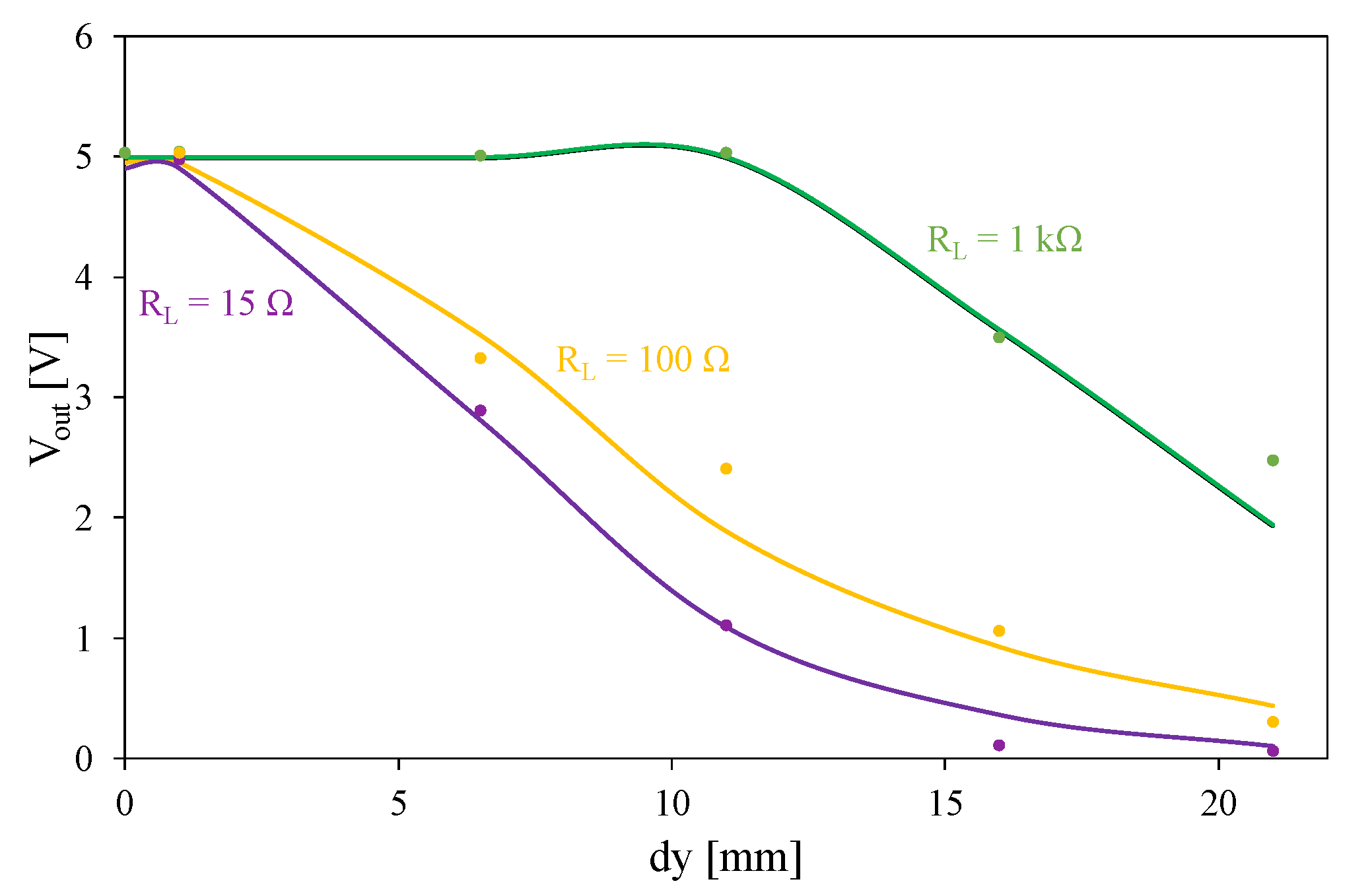
Figure 16 shows the influence of load resistance and the distance between the planes of the dy coils on the output voltage of the system under consideration.
It is worth noting that only at the highest of the considered resistance values for RL is the nominal value of the output voltage equal to 5 V with the distance between the dy windings exceeding 10 mm. For lower RL values, the nominal value of this voltage can only be obtained with a distance dy of up to 1 mm. For each of the considered values of RL, a decreasing dependence of the output voltage UR on distance dy was obtained. A decrease in the value of this resistance causes the considered characteristics to be shifted to the left. With resistance RL < 100 Ω and distance dy > 15 mm, the energy transmission to the load practically disappears.
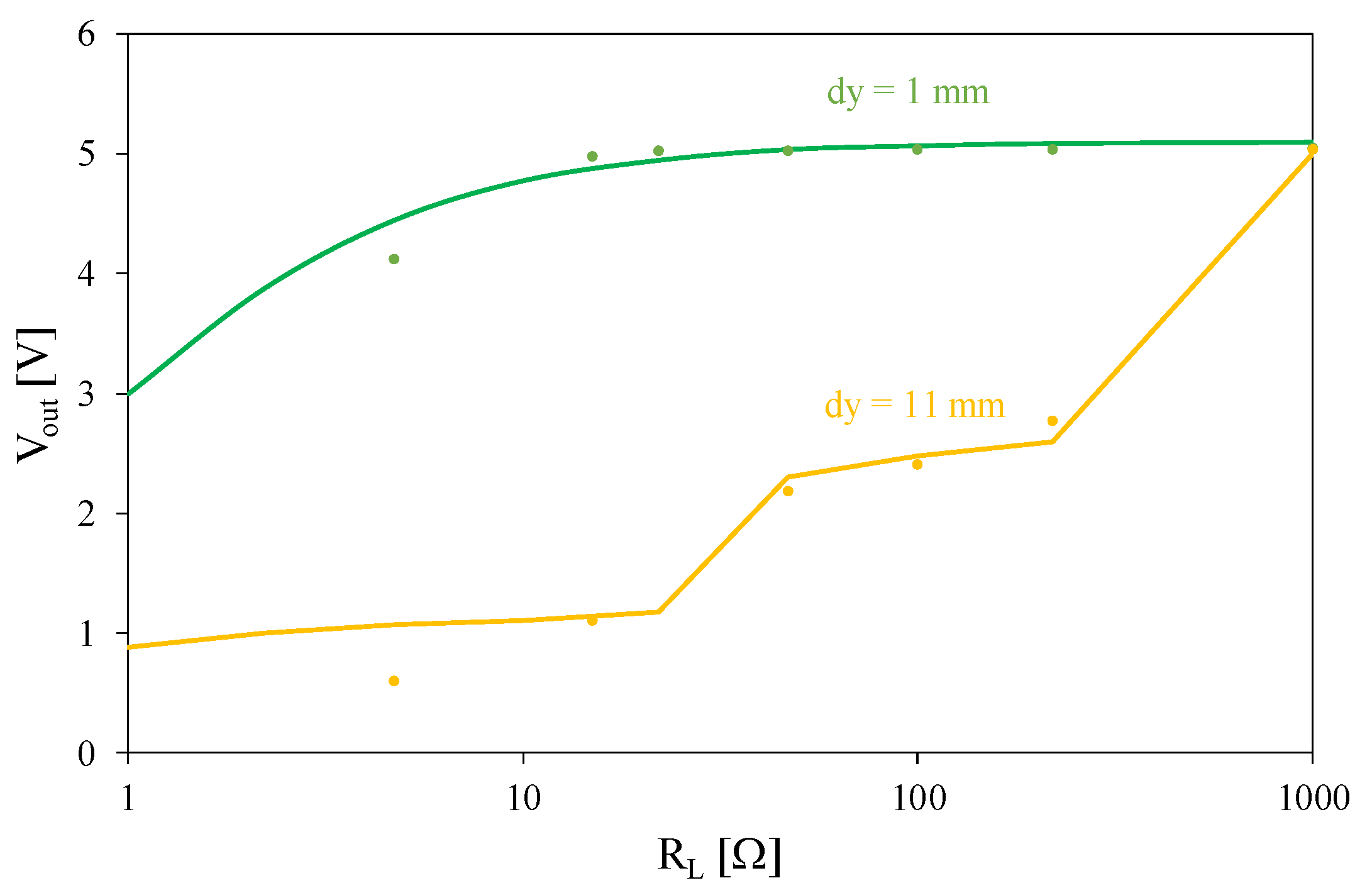
Figure 17 illustrates the influence of distance dy between the coils on the dependence of the output voltage on load resistance.
As can be seen, output voltage is an increasing function of load resistance. At the lower of the considered dy values, the system ensures stabilization of the output voltage for resistance RL above 15 Ω. This means that the nominal output voltage can only be obtained with a load current below 350 mA. This result is almost three times worse than the manufacturer’s data [36]. On the other hand, with the distance between the coils dy = 11 mm, the nominal value of the output voltage is obtained only at the highest of the considered resistance values, RL = 1 kΩ.
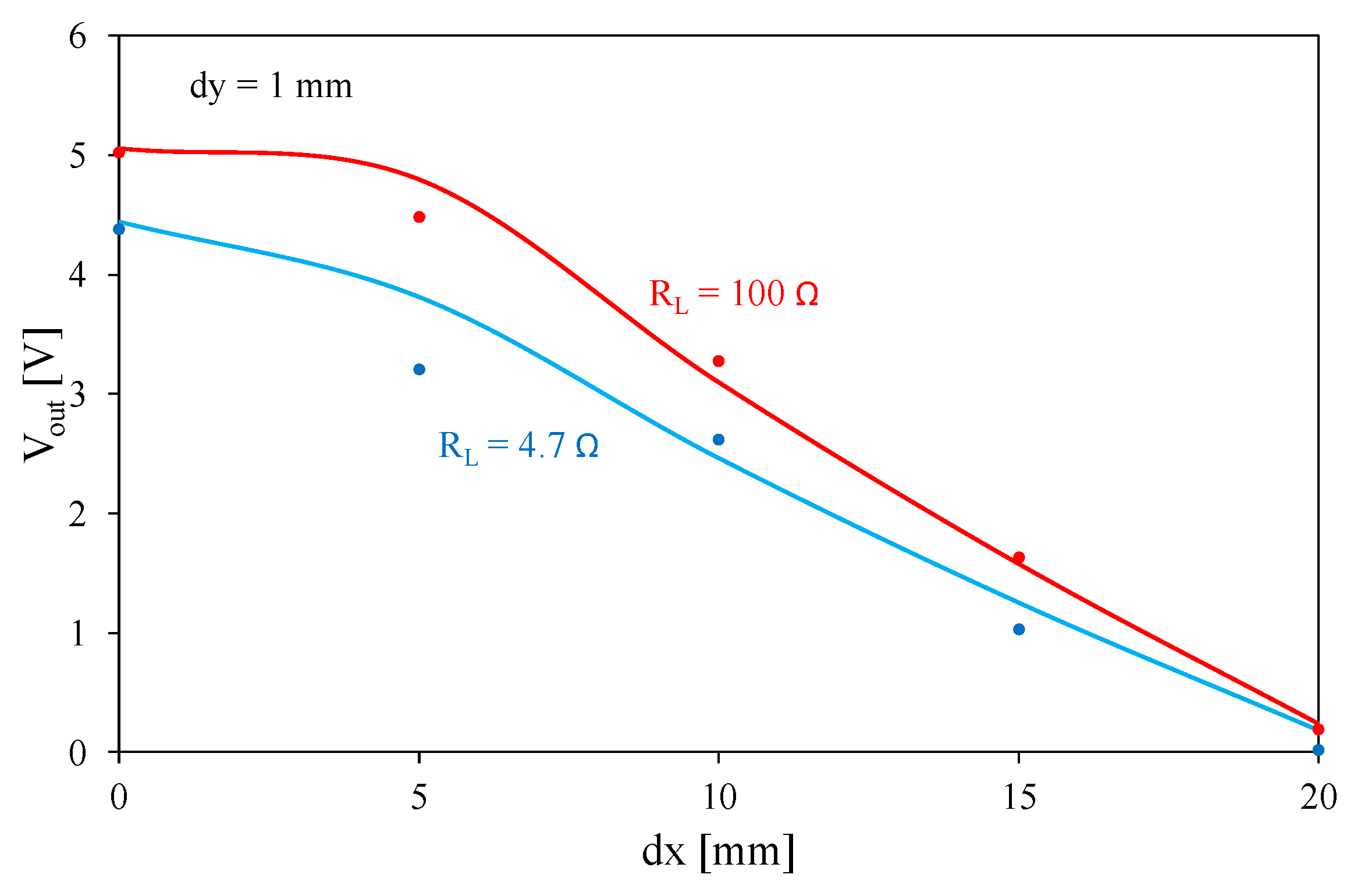
Figure 18 shows the dependence of the output voltage of the tested converter on the displacement between the axes of the windings dx at the fixed value of distance dy = 1 mm and selected values of load resistance.
The obtained dependence is a monotonically decreasing function. At a distance of dx = 20 mm, voltage Vout drops to a value close to zero. Voltage Vout values obtained for the lower of the considered RL resistance values are lower, too. It is worth noting that the nominal value of the output voltage equal to 5 V is obtained only for the higher of the considered load resistance values at a distance dx below 10 mm.
7. Conclusions
This paper presents the results of an investigation of an air transformer used in wireless power transfer systems and a selected system for such transfer. A compact electrothermal model of an air transformer was proposed. This model has the form of a subcircuit dedicated for SPICE software. With the use of this model, it is possible to compute characteristics of the considered transformer, taking into account both its electrical and thermal properties. Components occurring in the model are linear but its dependences on frequency and the distance between windings is taken into account. Due to the fact that self-heating and mutual thermal couplings between the windings are taken into account, it is possible to accurately compute the temperature on each winding. In comparison to the model described in the literature dedicated to analyses with the use of FEM, the proposed model makes it easy to estimate the model parameters, and a very short analysis time, which does not exceed a few seconds, is needed.
The correctness of the proposed model was verified experimentally for the transformer operating with resistive load. Additionally, this model was applied in computer analyses of a commercial WPT system. In both cases, a good agreement between the results of measurements and computations was obtained. This confirms the correctness of the proposed model.
From the investigation results, it can be seen that the characteristics of this device visibly change with a change in frequency and distance between the coils contained in this transformer. The dependence of the winding impedance as a function of frequency showed a significant increase in the resistance of the windings as a result of the skin effect phenomenon. With an increase in load resistance, the temperature of the windings of the air transformer decreases. Due to self-heating phenomena in each coil and mutual thermal couplings between these coils, the temperatures of both coils are higher than the ambient temperature. The thermal couplings play a bigger role when the distance between the coils is shorter. In our tests, at a low value of load resistance the temperature of the transformer coil may even reach 100 °C.
It was also shown that a shift between the windings in the direction of the horizontal and vertical axes as well as a change in load resistance significantly influence the output voltage of the wireless power transfer system. An increase in the distance between the windings causes a decrease in the value of the output voltage. With a distance between the windings greater than 15 mm or a shift of the axes of the windings with regard to each other by more than 20 mm, the power transfer between the windings practically disappears. The accuracy of the proposed model can be improved by taking into account changes in the resistances and inductances of the coils as a result of changes in the coils’ temperatures.
The results of this investigation may be useful for designers of WPT systems. A significant aspect for effective power transfer in WTP technology is the precise placement of the transformer windings on the same axis. It is also important that both windings are placed as close as possible to each other. The model of an air transformer presented here and the quantitative dependences obtained are characteristic only for the WPT system considered herein but the shape of these characteristics is universal and can be used to characterize properties of any WPT systems using inductive coupling between the input and output coils.
Author Contributions
Conceptualization, K.D., K.G. and P.P.; resources, K.D and P.P.; investigation, K.G. and K.D.; writing—original draft preparation, K.D., K.G. and P.P.; writing—review and editing, K.D., K.G. and P.P.; validation, K.G.; visualization, K.D. and K.G.; supervision, K.G. All authors have read and agreed to the published version of the manuscript.
Funding
This project was financed within the framework of the Ministry of Science and Higher Education program “Regionalna Inicjatywa Doskonałości” from 2019–2023, project number 006/RID/2018/19; sum of financing: 11,870,000 PLN.
Data Availability Statement
Data available for request.
Conflicts of Interest
The authors declare no conflict of interest.
References
- Alam, B.; Islam, N.; Bubhan, I.; Sarfraz, M. Analysis and Modelling of Basic Wireless Power Transfer Compensation Topology: A review. In Intelligent Data Analytics for Power and Energy Systems; Malik, H., Ahmad, M.W., Kothari, D., Eds.; Lecture Notes in Electrical Engineering; Springer: Singapore, 2022; Volume 802, pp. 501–515. [Google Scholar] [CrossRef]
- Valone, T.F. Geoengineering Tesla’s Wireless Power Transmission. ExtraOrdinary Science & Technology. 2017; pp. 31–42. Available online: https://www.researchgate.net/publication/320335847_Geoengineering_Tesla%27s_Wireless_Power_Transmission (accessed on 29 December 2022).
- Kurs, A.; Karalis, A.; Moffatt, R.; Joannopoulos, J.D.; Fisher, P.; Soljačić, M. Wireless power transfer via strongly coupled magnetic resonances. Science 2007, 317, 83–86. [Google Scholar] [CrossRef] [PubMed] [Green Version]
- Mohsan, S.; Khan, M.A.; Rokia, L.S.R.; Islam, A.; Mahmood, A.; Mazinani, A.; Amjad, H. A review on Research Challenges, Limitation and Practical Solution for Underwater Wireless Power Transfer. Int. J. Adv. Comput. Sci. Appl. 2020, 11, 554–562. [Google Scholar] [CrossRef]
- Coca, E. Wireless Power Transfer Fundamentals and Technologies; InTechOpen: London, UK, 2016. [Google Scholar]
- Moore, J.; Castellanos, S.; Xu, S.; Wood, B.; Ren, H.; Tse, Z.T.H. Applications of Wireless Power Transfer in Medicine: State-of-the-Art Reviews. Ann. Biomed. Eng. 2018, 47, 22–38. [Google Scholar] [CrossRef] [PubMed] [Green Version]
- Barbruni, G.L.; Ros, P.M.; Demarchi, D.; Carrara, S.; Ghezzi, D. Miniaturised Wireless Power Transfer Systems for Neurostimulation: A Review. IEEE Trans. Biomed. Circuits Syst. 2020, 14, 1160–1178. [Google Scholar] [CrossRef] [PubMed]
- Detka, K.; Górecki, K. Wireless power transfer—A review. Energies 2022, 15, 7236. [Google Scholar] [CrossRef]
- Barsukov, Y.; Qian, J. Battery Power Management for Portable Devices; Artech House Power Engineering: Norwood, MA, USA, 2013. [Google Scholar]
- Filipiak, M.; Głuchy, D. Analiza Wybranych Układów w Technice Bezprzewodowego Przesyłu Energii Elektrycznej. Poznan Univ. Technol. Acad. J. 2013, 74, 227–235. [Google Scholar]
- Okoyeigbo, O.; Olajube, A.; Shobayo, O.; Aligbe, A.; Ibhaze, A. Wireless power transfer: A review. IOP Conf. Ser. Earth Environ. Sci. 2021, 655, 012032. [Google Scholar] [CrossRef]
- Shan, D.; Wang, H.; Cao, K.; Zhang, J. Wireless power transfer system with enhanced efficiency by using frequency reconfigurable metamaterial. Sci. Rep. 2022, 12, 331. [Google Scholar] [CrossRef] [PubMed]
- Górski, K.; Kozieł, M.; Zawadzki, J.; Rosińska, K. Low power systems for energy harvesting [Układy do pozyskiwania energii elektrycznej małej mocy]. Przegląd Elektrotechniczny 2022, 98, 91–94. [Google Scholar]
- Ongaro, F.; Summerer, L. Peter Glaser lecture: Space and a sustainable 21st century energy system. In Proceedings of the 57th International Astronautical Congress, Valencia, Spain, 2–6 October 2006. Paper IAC-06-C3.1.01. [Google Scholar]
- Rim, C.T.; Mi, C. Wireless Power Transfer for Electric Vehicles and Mobile Devices; John Wiley and Sons: West Sussex, UK, 2017. [Google Scholar]
- Van den Bossche, A.; Valchev, V. Inductor and Transformers for Power Electronic; CRC Press: Boca Raton, FL, USA, 2005. [Google Scholar]
- Mou, X.; Sun, H. Wireless Power Transfer: Survey and Roadmap. In Proceedings of the 2015 IEEE 81st Vehicular Technology Conference (VTC Spring), Glasgow, UK, 11–14 May 2015; pp. 1–5. [Google Scholar] [CrossRef]
- Marcinek, M. Rezonansowy Układ Przekształtnikowy z Aktywną Stabilizacją Punktu Pracy w Systemach Bezstykowego Przekazywania Energii. Ph.D. Thesis, Zachodniopomorski Uniwersytet Technologiczny w Szczecinie, Szczecin, Poland, 2015. [Google Scholar]
- Kevin, L. Comparative Study of Different Coil Geometries for Wireless Power Transfer. 2016. Available online: http://utpedia.utp.edu.my/17133/1/Final%20Dissertation%20%28Final%29%20-%20Lau%20Kevin%2016392.pdf (accessed on 29 December 2022).
- Murakami, R.; Inamori, M.; Morimoto, M. Effects of Q factor on wireless power transmission by magnetic resonant coupling. In Proceedings of the 2016 IEEE International Conference on Power and Renewable Energy (ICPRE), Shanghai, China, 21–23 October 2016; pp. 139–143. [Google Scholar] [CrossRef]
- Wen, H.; Zhang, C. Investigation on transmission efficiency for magnetic materials in a wireless power transfer system. In Proceedings of the 2015 IEEE 11th International Conference on Power Electronics and Drive Systems, Sydney, Australia, 9–12 June 2015; pp. 249–253. [Google Scholar] [CrossRef]
- Imielski, A.; Wasowicz, S. Mutual inductance coefficient of air-core transformers. Archiv Elektrotechnik 1988, 71, 69–75. [Google Scholar] [CrossRef]
- Zeller, M. Właściwości układu bezprzewodowego przesyłu energii elektrycznej przy uwzględnieniu odkształceń prądów. Przegląd Elektrotechniczny 2019, 95, 102–109. [Google Scholar] [CrossRef]
- Agnaebrahimi, M.; Menzies, R. Air-core Transformer: A theoretical Analysis and Digital Simulations. In Proceedings of the International Conference on Power Systems Transients IPST’97, Seattle, WA, USA, 22–26 June 1997; pp. 117–122. [Google Scholar]
- Liao, Z.-J.; Wu, F.; Jiang, C.-H.; Chen, Z.-R.; Xia, C.-Y. Analysis and Design of Ideal Transformer-Like Magnetic Coupling Wireless Power Transfer Systems. IEEE Trans. Power Electron. 2022, 37, 15728–15739. [Google Scholar] [CrossRef]
- Fernández, C.; Prieto, R.; Garcia, O.; Cobos, J. Coreless Magnetic Transformer Design Procedure. In Proceedings of the 2005 IEEE 36th Power Electronics Specialists Conference, Dresden, Germany, 16 June 2005; pp. 1548–1554. [Google Scholar] [CrossRef]
- ElGhanam, E.A.; Hassan, M.S.; Osman, A. Design and Finite Element Modeling of The Inductive Link in Wireless Electric Vehicle Charging Systems. In Proceedings of the 2020 IEEE Transportation Electrification Conference & Expo (ITEC), Chicago, IL, USA, 24–26 June 2020; pp. 389–394. [Google Scholar] [CrossRef]
- Jayalath, S.; Khan, A. Design, Challenges, and Trends of Inductive Power Transfer Couplers for Electric Vehicles: A Review. IEEE J. Emerg. Sel. Top. Power Electron. 2021, 9, 6196–6218. [Google Scholar] [CrossRef]
- Rigot, V.; Phulpin, T.; Sadarnac, D.; Sakly, J. A new design of an air core transformer for Electric Vehicle On-Board Charger. In Proceedings of the 2020 22nd European Conference on Power Electronics and Applications (EPE’20 ECCE Europe), Lyon, France, 7–11 September 2020; pp. 1–9. [Google Scholar] [CrossRef]
- Liang, B.; Mao, Z.; Zhang, K.; Liu, P. Analysis and Optimal Design of a WPT Coupler for Underwater Vehicles Using Non-Dominated Sorting Genetic Algorithm. Appl. Sci. 2022, 12, 2015. [Google Scholar] [CrossRef]
- Pugi, L.; Grasso, F.; Paolucci, L.; Luchetti, L.; Zini, G. Finite Element Analysis of Copper Wire for Wireless Power Transfer Applications. In Proceedings of the 2022 IEEE 21st Mediterranean Electrotechnical Conference (MELECON), Palermo, Italy, 14–16 June 2022; pp. 801–806. [Google Scholar] [CrossRef]
- Stankiewicz, J. Comparison of the efficiency of the WPT system using circular or square planar coils. Przegląd Elektrotechniczny 2021, 97, 38–43. [Google Scholar] [CrossRef]
- Górecki, K.; Detka, K.; Górski, K. Compact Thermal Model of the Pulse Transformer Taking into Account Nonlinearity of Heat Transfer. Energies 2020, 13, 2766. [Google Scholar] [CrossRef]
- Górecki, P.; Górecki, K. Measurements and Computations of Internal Temperatures of the IGBT and the Diode Situated in the Common Case. Electronics 2021, 10, 210. [Google Scholar] [CrossRef]
- Catalog Data of WPT Systems. Available online: https://www.digikey.jp/htmldatasheets/production/2104059/0/0/1/106990017.html (accessed on 18 September 2022).
- Wireless_Power__SKU_DFR0362_-DFRobot. Available online: https://www.dfrobot.com/product-1284.html (accessed on 29 December 2022).
- AETECHRON. Catalog Data. Available online: https://www.google.com/url?sa=t&rct=j&q=&esrc=s&source=web&cd=&ved=2ahUKEwiJ8aO256D6AhWOxIsKHRm4D-UQFnoECAIQAQ&url=https%3A%2F%2Faetechron.com%2Fpdf%2Fservice%2F7228_OperatorManual.pdf&usg=AOvVaw0ZrUdH3pt-xIp7ZGSRwcwS (accessed on 18 September 2022).
- Technical Data FLIR i5. Available online: https://www.elfadistrelec.pl/Web/Downloads/n_/51/i5_60101-0201_en_51.pdf (accessed on 29 December 2022).
- Optex Product Information. Available online: http://www.dewetron.cz/optex/katlisty/PT-3S.pdf (accessed on 18 September 2022).
- Multimeter GWINSTEK LCR Meter Product Information. Available online: https://www.gwinstek.com/en-global/products/downloadSeriesDownNew/10096/742 (accessed on 12 October 2022).
Figure 1.
Network representation of the model of an air transformer.

Figure 2.
Air transformer under test.

Figure 3.
System for wireless power transfer.

Figure 4.
Tested WPT system with detailed diagrams of A and B blocks.

Figure 5.
System for measuring the properties of an air transformer.

Figure 6.
Setup for measuring WPT system properties.

Figure 7.
Stand for measuring the properties of the WPT system.

Figure 8.
Arrangement of the transmitting and receiving coils: horizontal position (a), vertical position (b).
Figure 8.
Arrangement of the transmitting and receiving coils: horizontal position (a), vertical position (b).

Figure 9.
Dependence of inductance (a) and series resistance (b) of the transmitting and receiving coils on the frequency of the exciting signal.
Figure 9.
Dependence of inductance (a) and series resistance (b) of the transmitting and receiving coils on the frequency of the exciting signal.

Figure 10.
Dependence of mutual thermal resistance between the coils on the distance between these coils.
Figure 10.
Dependence of mutual thermal resistance between the coils on the distance between these coils.

Figure 11.
Dependence of voltages on the transmitting and receiving coils (a) and their temperatures (b) on load resistance at two values of distance dy between these coils.
Figure 11.
Dependence of voltages on the transmitting and receiving coils (a) and their temperatures (b) on load resistance at two values of distance dy between these coils.

Figure 12.
Dependence of voltages on the transmitting and receiving coils on load resistance at selected values of frequency.
Figure 12.
Dependence of voltages on the transmitting and receiving coils on load resistance at selected values of frequency.

Figure 13.
Dependence of the transformer voltage ratio on the distance between transformer coils.

Figure 14.
Dependence of voltage on the receiving coil (a) and temperatures of both the coils (b) on load resistance at selected values of the distance dx between the axes of these coils.
Figure 14.
Dependence of voltage on the receiving coil (a) and temperatures of both the coils (b) on load resistance at selected values of the distance dx between the axes of these coils.

Figure 15.
Temperature distribution on the surface of the primary winding of the transformer at RL = 4.7 Ω and frequency of the excitation signal equal to 100 kHz.
Figure 15.
Temperature distribution on the surface of the primary winding of the transformer at RL = 4.7 Ω and frequency of the excitation signal equal to 100 kHz.

Figure 16.
Dependence of the receiver voltage on the distance between the coils in relation to the Y axis.
Figure 16.
Dependence of the receiver voltage on the distance between the coils in relation to the Y axis.

Figure 17.
Dependence of the output voltage on load resistance at selected values of distance dy between the coils.
Figure 17.
Dependence of the output voltage on load resistance at selected values of distance dy between the coils.

Figure 18.
Dependence of the voltage at the receiver and at the transmitter on the distance between the transmitting and receiving coils in relation to the X axis for two values of load resistance.
Figure 18.
Dependence of the voltage at the receiver and at the transmitter on the distance between the transmitting and receiving coils in relation to the X axis for two values of load resistance.


Table 1.
Values of the coefficients occurring in the formulas describing components occurring in the main circuit of the model of the air transformer.
Table 1.
Values of the coefficients occurring in the formulas describing components occurring in the main circuit of the model of the air transformer.
| Component | a | B | c |
|---|---|---|---|
| Lp | 0 | 5.6 pH/s | 3.55 μH |
| LS | 6 × 10⁻²⁰ H/s2 | −10−13 H/s | 9.11 μH |
| RP | 5.8 × 10⁻¹⁴ Ω/s2 | 2 × 10⁻⁷ Ω/s | 19 mΩ |
| RS | 5.6 × 10⁻¹³ Ω/s2 | 2 × 10⁻⁹ Ω/s | 55 mΩ |
Table 2.
Passive components in the transmitter system—block A.
| Component | Value | Component | Value | Component | Value |
|---|---|---|---|---|---|
| R1 [kΩ] | 2.7 | C1 [nF] | 1 | C4 [nF] | 39 |
| R2 [kΩ] | 30 | C2 [µF] | 47 | C5 [nF] | 39 |
| R3 [kΩ] | 30 | C3 [nF] | 39 | C6 [nF] | 39 |
Table 3.
Passive components in the receiver system—block B.
| Component | Value | Component | Value |
|---|---|---|---|
| R1 [kΩ] | 100 | C1 [nF] | 6.8 |
| R2 [kΩ] | 6.2 | C2 [µF] | 10 |
| R3 [kΩ] | 2 | C3 [µF] | 10 |
| L1 [µH] | 15 |
Table 4.
Manufacturer’s declared parameters of WPT.
| Parameter | Value |
|---|---|
| Input DC voltage [V] | 5 |
| Output DC voltage [V] | 5 |
| Maximum output DC current [A] | 1.2 |
| Distance (transmitter–receiver) [mm] | 2–10 |
Disclaimer/Publisher’s Note: The statements, opinions and data contained in all publications are solely those of the individual author(s) and contributor(s) and not of MDPI and/or the editor(s). MDPI and/or the editor(s) disclaim responsibility for any injury to people or property resulting from any ideas, methods, instructions or products referred to in the content. |
© 2023 by the authors. Licensee MDPI, Basel, Switzerland. This article is an open access article distributed under the terms and conditions of the Creative Commons Attribution (CC BY) license (https://creativecommons.org/licenses/by/4.0/).
Share and Cite
MDPI and ACS Style
Detka, K.; Górecki, K.; Ptak, P. Model of an Air Transformer for Analyses of Wireless Power Transfer Systems. Energies 2023, 16, 1391. https://doi.org/10.3390/en16031391
AMA Style
Detka K, Górecki K, Ptak P. Model of an Air Transformer for Analyses of Wireless Power Transfer Systems. Energies. 2023; 16(3):1391. https://doi.org/10.3390/en16031391
Chicago/Turabian StyleDetka, Kalina, Krzysztof Górecki, and Przemysław Ptak. 2023. "Model of an Air Transformer for Analyses of Wireless Power Transfer Systems" Energies 16, no. 3: 1391. https://doi.org/10.3390/en16031391
Note that from the first issue of 2016, this journal uses article numbers instead of page numbers. See further details here.