Article

Resource and Energy Saving Control of the Steelmaking Converter Process, Taking into Account Waste Recycling †

1
World Class Laboratory, Department of Computer-Aided Design and Control Systems, St. Petersburg State Institute of Technology, 190013 St. Petersburg, Russia
2
Department of Chemical Technology of Refractory Nonmetallic and Silicate Materials, St. Petersburg State Institute of Technology, 190013 St. Petersburg, Russia
*
Author to whom correspondence should be addressed.
This paper is an extended version of our paper published in 2019 IEEE 1st International Conference on Control Systems, Mathematical Modelling, Automation and Energy Efficiency (SUMMA), Lipetsk, Russia, 20–22 November 2019; pp. 523–526.
Energies 2023, 16(3), 1302; https://doi.org/10.3390/en16031302
Submission received: 19 December 2022 / Revised: 17 January 2023 / Accepted: 23 January 2023 / Published: 26 January 2023
(This article belongs to the Special Issue Smart Energy and Sustainable Environment)

Abstract

:
With the development of the energy control system of iron and steel enterprises, the urgency of solving the problem of the resource and energy saving control of steelmaking processes increases, taking into account the reconfiguration of production to a new task, intensification of the processes of recycling of raw materials, as well as reducing the waste intensity of production. The way to solve the problem of resource and energy saving of steelmaking production is the creation of a computer system. It allows one to analyze the state of the refractory converter lining, calculation of the material and thermal balances, the amount of slag-forming materials, the quantitative characteristics of slag corrosion, as well as predict the phase and chemical composition of the slag in order to impart the properties necessary in the production of mineral binders and other building materials. The computer system allows one to identify complex fuzzy relationships between process parameters and issue recommendations on the resource and energy saving control of the converter process, taking into account the waste recycling. The testing of the computer system, according to the industrial data of the enterprises CherMF (PJSC Severstal) and PJSC NLMF, confirmed its operability and the possibility of its use at iron and steel enterprises.

1. Introduction

For the effective development of iron and steel enterprises, a necessary condition is the presence of a developed energy management system. The interaction of the components of a single energy–metallurgical technological complex significantly determines the energy efficiency of the entire metallurgical enterprise as a whole. The efficiency of the complex is determined not only by the energy efficiency of the functioning of individual metallurgical units, but also by their system integration with the tasks of the efficient resource-saving control.
Currently, an extensive literature is devoted to the research of metallurgy steelmaking industries, which reflects the individual stages of solving resource and energy conservation issues.
The following scientists made a great contribution to solving energy saving problems: Danilov N.I. [1], Lavrov V.V. [2], Lisienko V.G. [3,4], Spirin N.A. [2], Shchelokov Ya.M. [4], (UrFU, Yekaterinburg); Kazarinov L.S. [5,6], Barbasova T.A. [5], and Kolesnikova O.V. [6] (SUSU (SRU)); Roskilly A.P. [7], Kumar D.S. [8], Jiang L. [9], Holappa L.E. [10], etc.
In the field of chemical technology of high-temperature materials and fire-resistant lining of thermal units, the works of Suvorov S.A. (SPbSIT (TU), St. Petersburg), Kuznetsov D.V. (MISIS, Moscow) [11], Borovik S.I. [12] (SUSU (NRU), Chelyabinsk), Sheshukov O.Yu. [13] (IMET UB RAS, Ekaterinburg), Aneziris C. [14], Sadrnezhaad S. K. [15], Hocquet S. [16], Cecca C. D. [17], etc., should be noted.
The works of the authors Shapovalov A.N. [18] (MISIS, Moscow), Korneeva A.A. [19,20,21] (SFU, Krasnoyarsk); Grigorovich K.V. [22] (IMET RAS, Moscow); Bigeeva V.A. [23] Wen D. are devoted to the issues of mathematical modeling of steelmaking processes., Zhu, Y. [24]; Cao L. [25]; Bi Lu [26] et al.
Despite the successes achieved, the integrated resource and energy saving control problem in the metallurgical technological complex is currently not sufficiently solved. The fact is that the efficiency of the metallurgical production should be determined not only by the energy efficiency of the functioning of individual metallurgical units, but also by their system integration with the tasks of effective resource-saving control. From the point of view of resource and energy saving, the components of the energy and metallurgical technological complex are interconnected into a single system [27,28,29]. Therefore, there is a need for the integrated interconnected control of energy and material resources at metallurgical enterprises [30,31,32].
A distinctive feature of this work is the implementation of the methodology of an integrated approach to solving the resource and energy saving control problem, taking into account the reconfiguration to a new production task, increasing the refractory converter lining life, compliance with environmental safety requirements, as well as reducing not only energy consumption, but also the waste intensity of production.
Technological high-temperature processes of steel production are characterized by the formation of waste in the form of slurries, slags, wastewater containing various chemical components, the battle of refractories, scrap, and scale that pollute the environment [33,34,35,36]. The works of Holappa L. [37], Heikkinen E. [38], Salman M. [39], Rosales Garcia J. [40], Sheen, Y.-N. [41], and others are devoted to this direction. At the same time, the development of technologies for recycling metallurgical waste into useful products is currently of particular relevance. For example, blast furnace and steelmaking slags can be used in the production of clinkers for binders, fiberglass, slag, and other heat-insulating building materials, cast stone products, and in bitumen–mineral mixtures, as well as fillers in concrete, as components of autoclave binder in the production of silicate bricks.
Thus, the key objectives of sustainable resource and energy efficient development of metallurgical industries are:
  • Reducing energy consumption, material consumption, waste output, and increasing the degree of their processing;
  • Increase in the life of trouble-free operation of metallurgical units;
  • Reducing of the negative impact of the steelmaking products on the environment during the product life cycle—from the extraction of raw materials to utilization of products;
  • Implementation of requirements on the amount of discharges and emissions.
The solution of these problems is most relevant for converter processes that make up the leading industrial group of metallurgy industries [42,43,44,45]. The difficulty of controlling the converter process is associated with the effect of random disturbances (for example, contamination of scrap with rust and foreign materials), working in conditions of insufficient information about the process parameters (for example, the presence of fuzzy data about the scrap chemical composition), high energy intensity of the process, as well as requirements for the environmental performance of production (for the amount of slag formed, carbon dioxide emissions, etc.) [46]. The tools for effectively solving the resource and energy saving problem in steelmaking is the creation of a computer system that allows you to search for acceptable values of controlled process variables (flux mass, blast volume, and blast time) [47], selection of control criteria (productivity, converter energy consumption, and output (mass) steel), as well as criteria limitations (the loss of refractory lining mass; the ultimate solubility of the refractory phase in the converter slag).
Thus, the purpose of this work is to increase the efficiency of reconfiguring the converter control system by creating a computer system that allows, on the basis of a library of mathematical models, one to issue recommendations to control production personnel on resource and energy saving control the converter steelmaking process. This goal is due to the need to increase the life of the refractory converter lining while meeting the requirements for the quality of finished products, energy consumption, and waste capacity of production.
The use of a computer system at metallurgical enterprises makes it possible to increase the life of trouble-free operation of converters, reduce the time spent on reconfiguring production, improve product quality, and also reduce the negative impact of waste (slag; carbon dioxide emissions) on the environment.
The results obtained provide an increase in the number of smelters, environmental safety, energy, and resource conservation of metallurgical enterprises, which is a key direction of the metallurgical industry. The level of efficiency of the metallurgical enterprises ensures the stable operation of various processing and machine-building enterprises. The possibility of using the presented methodology for the integrated solution of the resource and energy saving problems of converter processes by international metallurgical corporations should be noted.

2. Methodology of the Resource and Energy Saving Control of the Converter Process

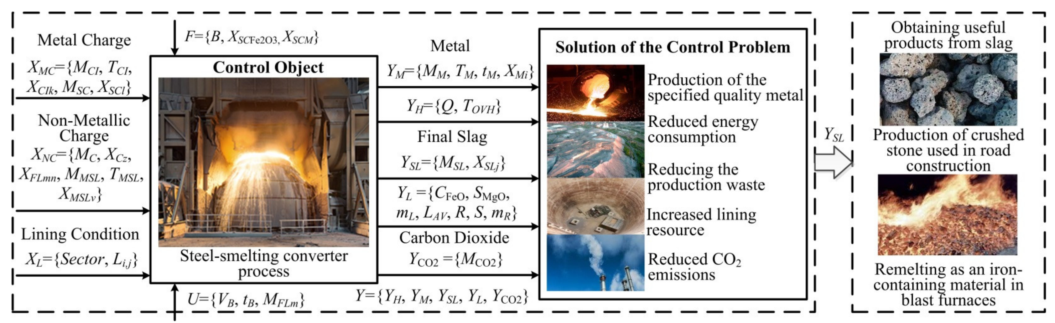
2.1. Statement of the Control Problem of the Steelmaking Converter Process

The converter steel melting process is a complex set of physico-chemical and thermal processes. The insufficient current information about melting parameters, the constant change in temperature and composition of materials, require systematic correction of steel melting technology [18,43,44]. The starting materials of the converter process are liquid cast iron, solid metallic charge (scrap metal, waste, pellets or briquettes, and solid pig iron), and slag-forming materials, as well as deoxidizers and alloying materials.
The process of converter melting begins with an inspection of the surface of the converter lining and a decision to restore its operability if necessary [48,49,50]. The localization of increased wear areas of the refractory lining consists in searching for sections, the residual thickness of which is less than the average value obtained. The assessment of the identified areas volume of increased local wear of the lining is carried out using the analysis of scanograms. The scanogram is an expanded image of the working lining. The residual thickness of the working lining is encoded in the form of a color scale, as shown in Figure 1. Cold shades, starting from blue, mean an unchanged starting thickness of the refractory, warm shades up to red indicate areas with extreme wear of the working lining to zero residual thickness of the working periclase-carbon layer. The obtained results of pixel integration of scanograms allow us to determine the necessary consumption of repair materials, taking into account the real scale to the converter lining, during hot repairs by semi-dry, flare shotcrete, or welding.
After making a decision on the start of converter melting, the permissible amount of scrap, cast iron, slag-forming materials, and oxygen is determined, which ensures the production of metal with a given mass, temperature, and carbon concentration, as well as the basicity of the final slag at the end of blasting.
The converter melting cycle is 30–50 min, depending on the capacity of the unit, the intensity of the blast supply, and the organization of production. Measurements of the converter process variables are carried out at the beginning of the steel melting process and at its completion. Controlled process variables are: blast volume VB, blast time tB, and mass of fluxes MFL. As controlled uncontrolled variables during melting, there are the mass MCI and the chemical composition of cast iron XCI, cast iron temperature TCI, mass MSC, and the scrap chemical composition XSC [18,19,20,21].
The converter steelmaking process as a control object is characterized by a set of variables Y = f(X, U, F), where Y = {YH, YM, YSL, YL, YCO2}—vector of output variables: YH = {Q, TΠEP}—variables characterizing data on heat consumption during melting: Q—total heat consumption, kJ; TOVH—the temperature of overheating of the metal above the temperature of the beginning of solidification, °C; YM = {MM, TM, tM, XMi}—variables characterizing data about the metal: MMmass of metal, kg; TM—temperature of metal, °C; tM—duration of metal output, s; XMi—metal chemical composition, i = {C, Si, Mn, Cr, S, P, Cu, Ni}, %mass.; YSL = {MSL, XSLj}—variables characterizing the final slag data: MSLmass of the final slag, kg; XSLj—final slag chemical composition, j = {CaO, SiO2, MgO, FeO, Al2O3, MnO, P2O5, S}, %mass.; YL = {CFeO, SMgO, mL, LAV, R, S, mR}—variables characterizing data on the effect of slag on the refractory converter lining: CFeO—oxidation of slag; SMgO—the ultimate solubility of the refractory phase (MgO) in the converter slag; mL—mass loss of lining, kg; LAV—massed average residual thickness of the working lining, m; R—repairs type; S—the area of the damaged section of the lining, m2; mR—the amount of repair mass, kg; YCO2 = {MCO2}—variables characterizing carbon dioxide emissions: MCO2carbon dioxide emitted mass, kg;
X = {XMC, XNC, XL}—vector of input variables: XMC = {MCI, TCI, XCIk, MSC, XSCl}—variables characterizing metallic charge data: MCI—cast iron mass, kg; TCI—cast iron temperature, °C; XCIk—cast iron chemical composition, k = {Si, Mn, C, P, S}, %mass.; MSC—scrap mass, kg; XSCl—scrap chemical composition, l = {Si, Mn, C, P, S}, %mass.; XNC = {MC, XCz, XFLmn, MMSL, TMSL, XMSLv}—variables characterizing nonmetallic charge data: MC—cooler mass, kg; XCz—cooler chemical composition, z = {CaO, SiO2, Al2O3, MnO, Fe2O3, FeO, Fe}, %mass.; XFLmn—slag-forming materials (fluxes) chemical composition, m = {lime, dolomite, magnesia fluxes}, n = {CaO, SiO2, MgO, Fe2O3, FeO, MnO, Al2O3, CaCO3, MgCO3}, %mass.; MMSL—mass of mixer slag, kg; TMSL—mixing slag temperature, °C; XMSLv—mixer slag chemical composition, v = {CaO, SiO2, MgO, Fe2O3, FeO, MnO, Al2O3}, %mass.; XL = {Sector, c, Li,j}—variables characterizing the condition of the converter lining: Sector—sector name; c—color characteristics; Li,j—the thickness of the converter lining in each pixel, of which the oxygen converter lining scanogram consists, mm;
U = {VB, tB, MFLm}—vector of control actions: VBblast volume, m3; tBblast time, s. [51], MFLm—mass of fluxes, kg;
F = {B, XSCFe2O3, XSCM}—vector of disturbing influences: B—basicity of slag (CaO/SiO2); XSCFe2O3—rust contamination of scrap, %mass.; XSCM—contamination of scrap with extraneous materials, %mass.
A formalized description of the process of converter melting of steel as a control object is shown in Figure 2.
Based on the proposed formalized description, the task of resource and energy saving process control is formulated as follows:
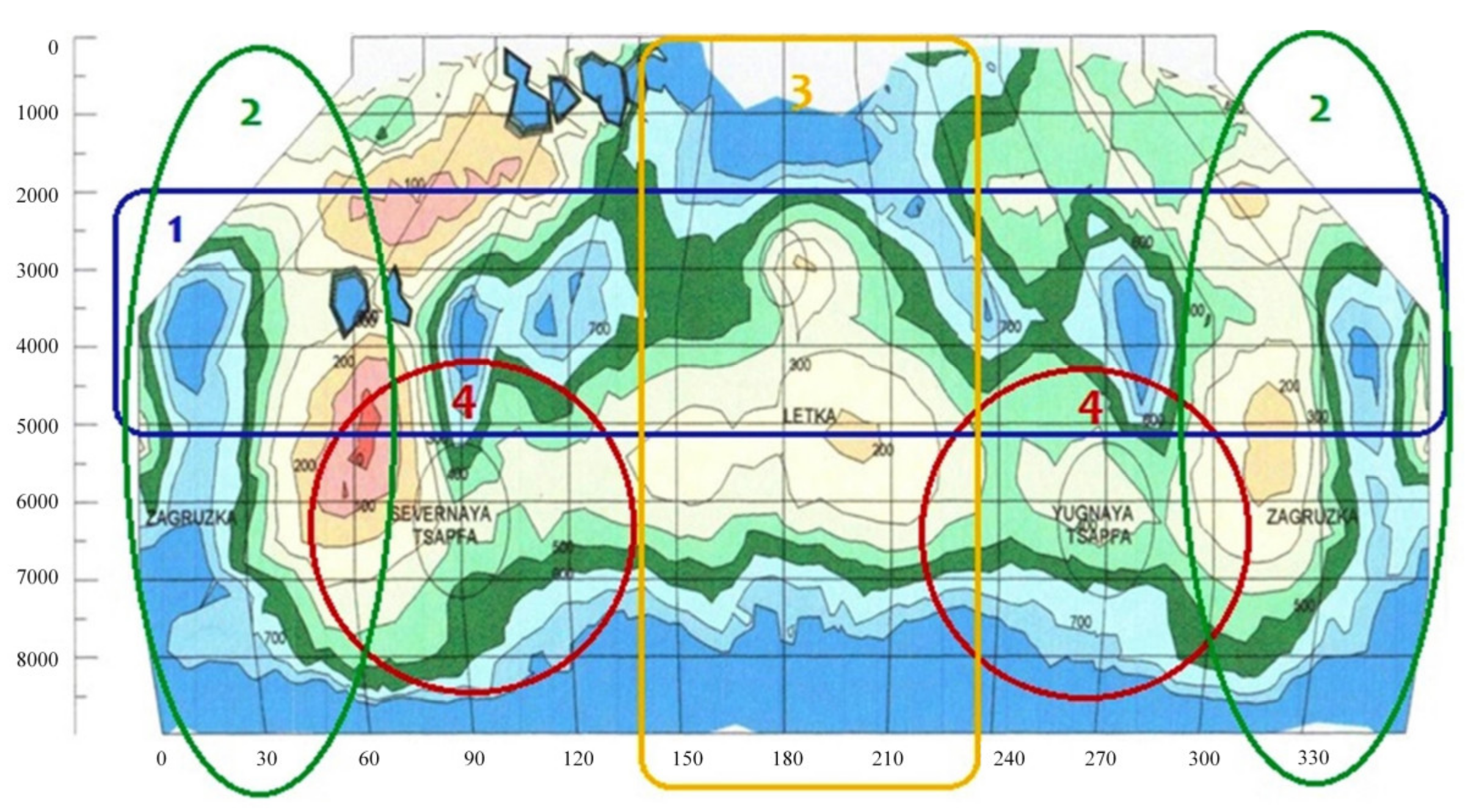
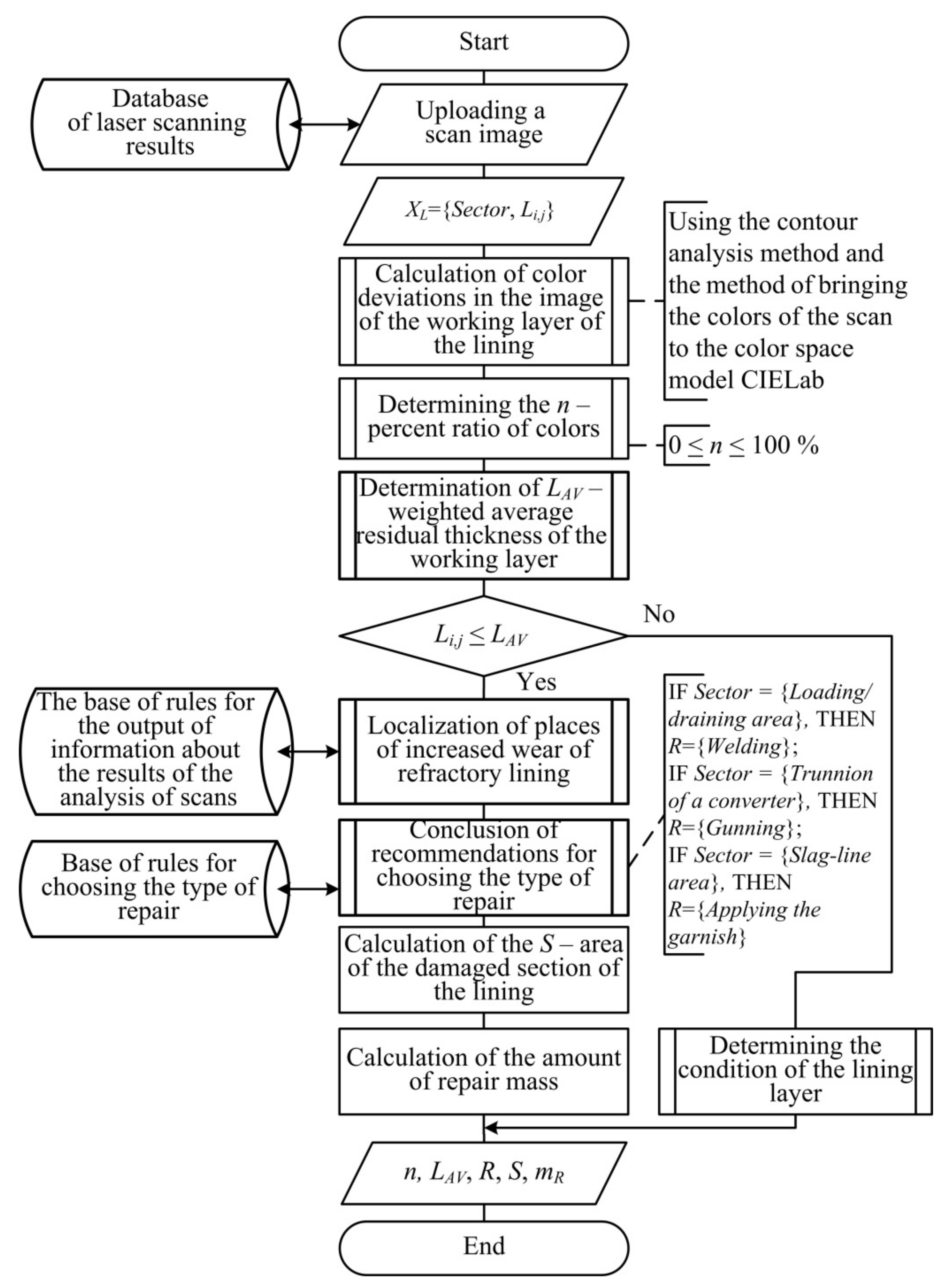
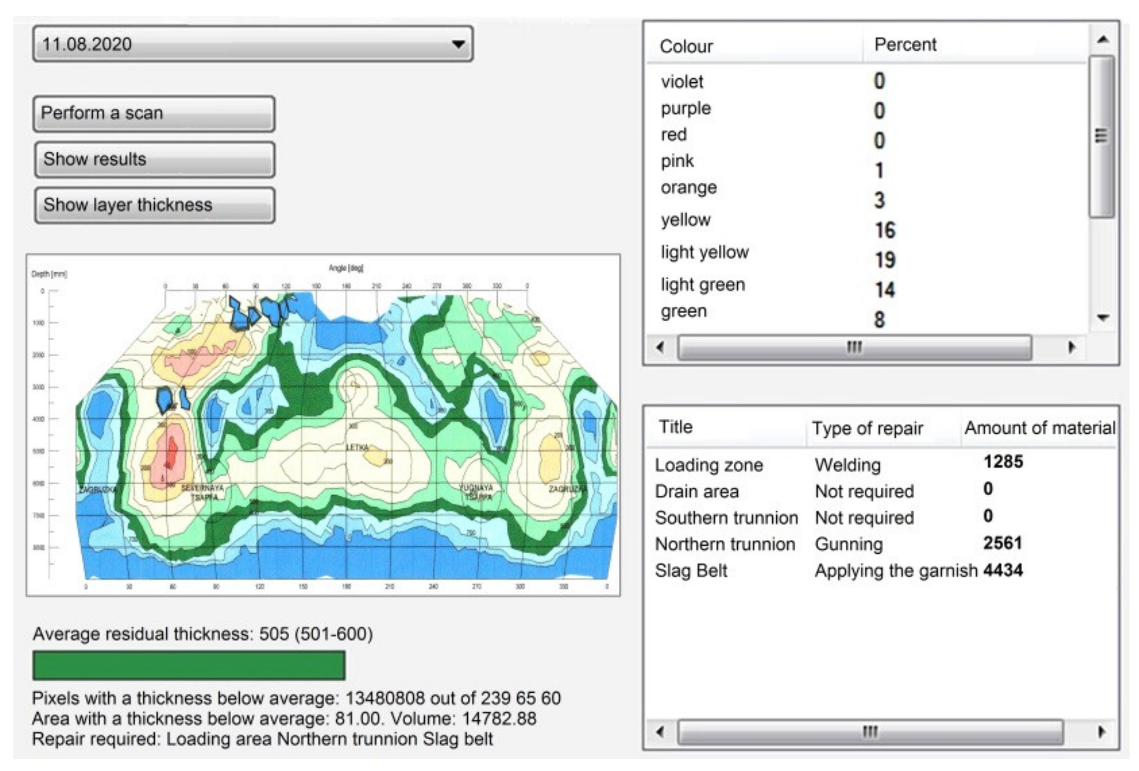
  • For the given input variables {Sector, c, Li,j}, it is necessary to determine the percentage of colors on the converter lining scanogram, the wear rate degree, the converter lining condition, the type of repair work (if necessary) {LAV, R}, calculate the indicators of the converter lining damaged sections {S, mR}, and issue recommendations on the start of the process. The obtained estimates of the average residual thickness of the working converter lining, area, volume, and dislocation of places of increased local wear of the lining during the campaign allow us to determine the patterns of destruction and analyze the quality of the refractory converter lining.
  • Based on the input data on the parameters of the charge X = {XMC, XNC}, the required quality composition {XM}, metal mass {MM}, and temperature {TM}, it is necessary to determine the permissible values of control actions Up = {VB, tB, MFLm}, ensuring the fulfillment of criteria restrictions Gq = {Q, TOVH, TM, MSL, CFeO, SMgO, mL, MCO2}.
The quantity, chemical composition, viscosity, and rate of slag formation have a significant impact on the quality of steel, the yield of usable metal, as well as slag wear of the refractory converter lining.
The negative effect of converter slag consists in the corrosive destructive effect on the refractory converter lining [11,52,53,54]. At the same time, the chemical composition and amount of the formed slag is determined by the metallic charge composition {XSC, XCI}, mass of slag-forming materials {MFL}, the metal indicators at the end of the blasting {YM}, as well as the required slag basicity B. The determination of the permissible composition of converter slag to reduce the wear of the refractory lining is based on the principle of increasing the saturation of the slag with the refractory phase by increasing the current concentration (MgO) and reducing the saturation concentration (MgO) with increasing the basicity of the slag (CaO/SiO2).
It should be noted that waste from the steelmaking process—converter slags belonging to hazard class 4 (code 35121002204 according to the Federal Classification Catalog of Waste of the Russian Federation), can be used in the production of crushed stone used in road construction, as well as an iron-containing material for secondary remelting in blast furnaces. Therefore, predicting the phase composition of slags and modifying their chemical composition is practically an important task not only from the point of view of increasing the life of the refractory converter lining, but also providing the necessary properties for the further production of useful products.

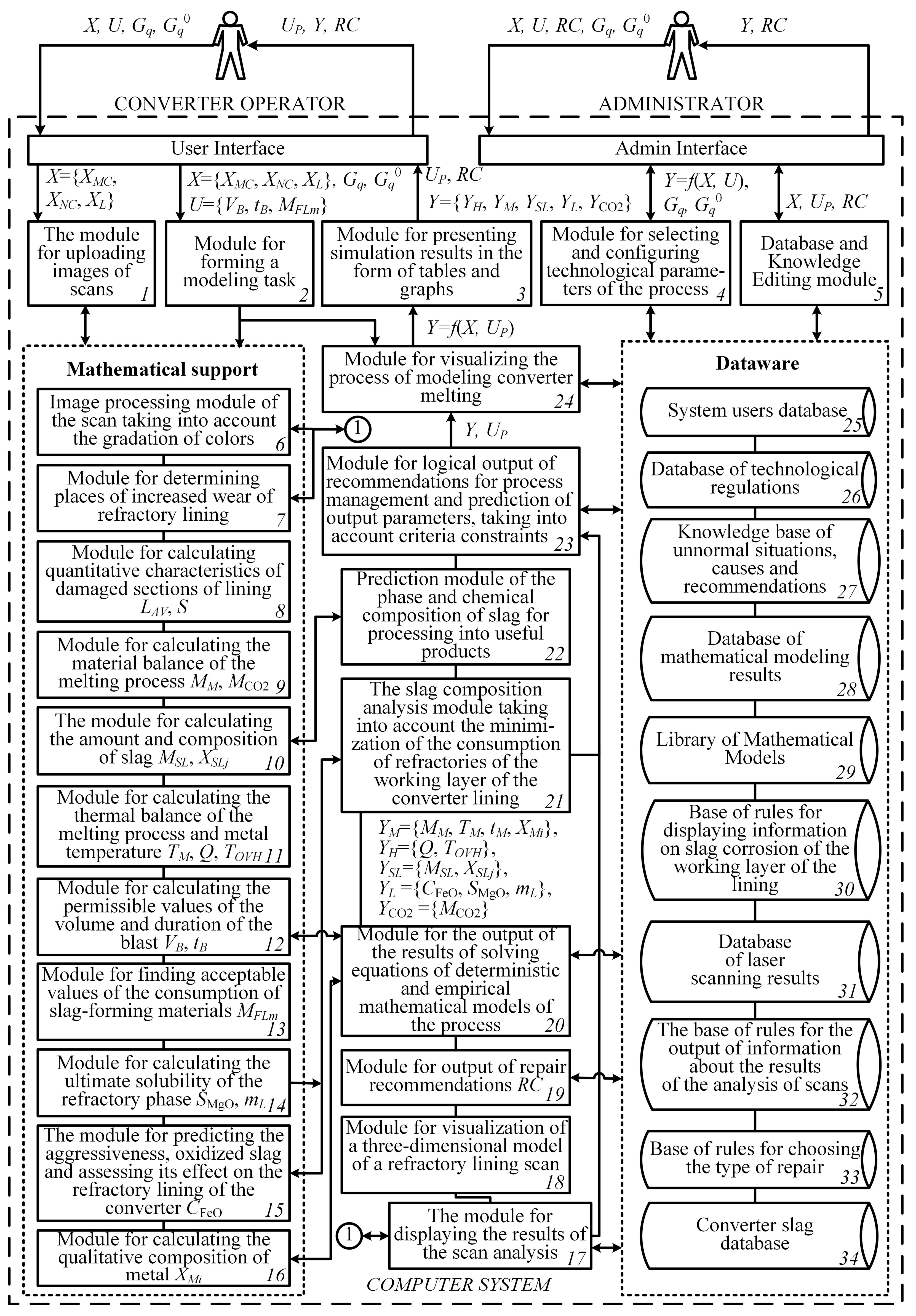
2.2. Functional Structure of a Computer System for Control of a Steelmaking Converter Process

To solve the resource and energy saving control problem of the steelmaking converter process, taking into account waste recycling, a functional structure of a computer system is proposed [55], and is presented in Figure 3.
The computer system is based on mathematical support, which includes a configurable library of deterministic and empirical mathematical models. The library of mathematical models allows you to calculate, predict, and visualize the values of key parameters of the converter process Y = {YH, YM, YSL, YL, YCO2} and includes a system of equations consisting of:
  • Equations for calculating the geometric characteristics of the damaged sections of the refractory converter lining and the mass of the necessary repair materials;
  • Material balance equations for calculating the mass and composition of steel, the mass of carbon dioxide released, and the mass and composition of the resulting slag;
  • Heat balance equations for calculating the total heat consumption, metal, and overheating temperatures;
  • Equations for calculating the slag corrosion characteristics;
  • Equations for calculating the ultimate solubility of the refractory phase in converter slag.
The modules of the computer system 1, 6–8, and 17–19, the numbering of which is shown in Figure 3, allow one to issue recommendations RC for the safe operation of the converter lining. The solution of this problem is carried out in two stages.
1.
Generation of images indicating the date, time, and number of melting, as well as the degree of wear of the working lining. The operation of the converter is subject to an operating restriction with a residual lining layer of less than 40% of the initial state. Further converter operation is dangerous.
The key characteristic of the image generation process is the consideration of the moment of repair work and their quality, which determines the further stage of the converter life cycle for each of the zones of increased wear.
2.
Determination of the average residual thickness of the working layer, localization of places of increased wear, determination of their surface area and volume, as well as the conclusion of recommendations on the type of repair and selection of repair materials.
In the process of pixel-by-pixel image analysis of laser scanning results, it is necessary to determine the number of pixels related to each of the possible color shades. To do this, we solve the problem of comparing the color of each pixel with a set of reference values for classifying the pixels of the scan. The array of color characteristics of the image represents the values of red, green, and blue in RGB format. To calculate the shade deviation from the standard, it is necessary to convert the color values from the RGB color model format to the LAB format.
The calculation of the color deviation is made according to the equation:
Δ E i = ( L i L j e t ) 2 + ( a i a j e t ) 2 + ( b i b j e t ) 2 ,
where
Δ E i —the color deviation of the i-th pixel of the scan image from the reference color value, i = 1..m, m—number of pixels;
L i , a i , b i —color coordinates of the LAB space in the i-th pixel of the scan image;
L j e t , a j e t , b j e t —reference color values j, j = 1..q, q—the number of reference color characteristics.
The result of the performed operations is a data set in which each shade of color corresponds to the pixels’ number found on the scanned image of the refractory lining scanogram.
Medium-sufficient thickness of the refractory lining L A V is calculated using the following equation:
L A V = i = 1 n P i n ,
where P i —the thickness of the lining in the i-th significant pixel, m, a significant pixel is a pixel whose color corresponds to a certain thickness of the refractory layer.
The refractory lining surface area in one pixel is calculated by the equation:
S i = w r w h r h ,
where
w —converter width, m;
r w —the number of pixels in the scan image horizontally;
h —converter height, m;
r h —the number of pixels in the scan image vertically.
The damaged section surface area of the refractory lining is calculated by the equation:
S = i = 1 i = n k i S i ,   k i = { 1 ,   P i < C 0 ,   P i C   ,
where
k i —coefficient of accounting for the damaged section of the refractory lining;
C —the minimum allowable thickness of the lining layer, m.
The volume of the damaged section to be repaired is calculated by the equation:
V = i = 1 i = n k i S i ( C P i ) .
The mass of the repair mixture for repairing the damaged section is calculated by the equation:
m R = V ρ ,
where
V —the volume of the damaged section of the refractory lining to be repaired, m3;
ρ —density of the material used for repair, kg/m3.
The following conditional production rules are used in the computer system to evaluate the life of the trouble-free operation of the oxygen converter:
IF the average residual thickness of the converter lining is less than 40% of the original, THEN the lining is in an emergency condition;
IF the ratio of the thickness of the repair layers to the actual residual layer of the refractory exceeds 1/2, THEN the lining is in an emergency condition.
The main places of increased local wear of the refractory converter lining are the zones of charge loading and metal discharge near the outlet, as well as trunnion zones.
Computer system modules 2, 3, 9, 10, 16, 20, and 24 allow one to determine the mass and composition of metal, the mass and composition of slag, as well as the mass of CO2 based on the results of solving the equations of material balance:
The mass of metal is determined by the following dependence:
M M = M C I + M S C + M F e N M M I M M F e S L M R E L M F e R E L M F e D
where
M F e N M —weight of iron recovered from non-metallic materials, kg;
MIM—mass of oxidized impurities, kg;
M F e S L —the mass of iron oxidizing to FeO and Fe2O3 passing into slag, kg;
MREL—total number of removals and emissions, kg;
M F e R E L —the mass of iron lost with removals and emissions, kg;
M F e D —weight of iron lost with dust, kg.
Total slag mass MSL is determined by the equation:
M S L = 100 · M E O / ( 100 X F e O S L X F e 2 O 3 S L ) ,  
where MEO—mass of oxides formed during melting and introduced by lime (except iron oxides), kg.
Module 12 of the system allows you to determine the blast flow rate, which is determined by the oxygen balance equations. In addition to blasting, oxygen enters the converter bath during the decomposition of iron oxides of non-metallic materials, and is consumed not only for the oxidation of metal impurities, but also for the afterburning of a part of CO to CO2, iron oxidation, and also partially dissolves in metal and is lost into the gas phase at the beginning of the purging.
V B = ( M R + M R · X O 2 L / 100 ) · 100 · V m / X O 2 B · M O 2 ,  
where
M R —total oxygen demand of the blast for oxidative refining, kg;
X O 2 L —oxygen loss in the gas phase and its dissolution in the metal, %;
V m —molar volume of oxygen, mol/l;
X O 2 B —oxygen content in the blast, %;
M O 2 —molar mass of oxygen, g/mol.
The total oxygen demand of the blast for oxidative refining is determined by the equation:
M O 2 = M O 2 I M + M O 2 F e + M O 2 C O M O 2 N M ,
where
M O 2 I M —mass of oxygen for oxidation of metal impurities, kg;
M O 2 F e —mass of oxygen for iron oxidation, kg;
M O 2 C O —mass of oxygen for afterburning CO, kg;
M O 2 N M —the mass of oxygen from the decomposition of iron oxides of non-metallic materials, kg.
The duration of the main technological period of melting—purging is defined as the time required to inject the calculated amount of oxygen into the converter:
t B = V B / I B ,
where I B —purge intensity, m3/s.
The modules of the computer system 11, 20, 24, based on the results of calculating the heat balance equations, allow for determining the total heat consumption, the overheating temperature, and the temperature of the metal at the end of the purge.
The total heat input is determined from the equation
Q i n = Q C I + Q M C I M + Q F e O + Q S L F + Q C O  
where
QCI—the amount of heat from liquid cast iron, which is determined by the known values of the temperature of cast iron and its consumption, kJ;
Q M C I M —the amount of heat from the oxidation of metallic charge impurities, kJ;
Q F e O —the amount of heat from iron oxidation, kJ;
Q S L F —the amount of heat from the formation of compounds in the slag, kJ;
Q C O —the amount of heat from afterburning CO, kJ.
Consumption items of the heat balance
Q o u t = Q M + Q S L + Q G + Q F e + Q R E L + Q D + Q C + Q H L
where
QM—the amount of heat from the molten metal, kJ;
Q S L —the amount of heat from the slag, kJ;
Q G —the amount of heat from the exhaust gases, kJ;
Q F e —the amount of heat from the decomposition of iron oxides entering the converter with non-metallic materials, kJ;
Q R E L —heat losses with outflows and emissions, kJ;
Q D —the amount of heat for dust formation, kJ;
Q C —the amount of heat spent on the decomposition of carbonates, kJ;
Q H L —heat losses, kJ.
Based on the heat balance equations, the temperature of the metal can be determined by the equation:
T M = ( Q i n ( Q G + Q F e + Q R E L + Q D + Q C + Q H L ) q M M M + q S L M S L c M M M + c S L M S L ,
q—specific heat of combustion, kJ/kg;
c—specific heat capacity, kJ/(kg∙K).
After calculating the metal temperature, the amount of overheating of the metal over the temperature of the beginning of solidification is determined
T O V H = T M T M E L ,
where T M E L —the temperature of the beginning of the solidification of the metal, °C.
The value of the overheating temperature of the metal should be in the recommended temperature range for the specified method and casting conditions. In case of deviations of the specified values, it is necessary to adjust the scrap metal consumption until the temperature value is obtained in the range of permissible deviations.
The temperature of the metal at the end of the purging depends on the carbon content in the metal, the method of bucket processing, and the type of casting, as this determines the necessary heat reserve of the metal to keep it in a liquid state before casting. The computer system includes software modules that allow for calculating the quantitative characteristics of slag corrosion, the amount of slag forming materials, and analyzing the aggressiveness of the slag melt 13–15, 21, 23, as well as predicting the phase and slag chemical composition 22 in order to impart the properties necessary for processing.
The empirical model for estimating slag oxidation CFeO = f{XCC, B, Z} is obtained from the results of the experimental studies [11], where XCCrequired concentration of carbon in the metal, Z—empirical coefficients. The higher the oxidation of the slag, the higher its aggressiveness towards the refractory converter lining.
The wear dynamics of periclase-carbon refractory is determined mainly by the dissolving ability of the slag melt in relation to the main (periclase) component of the refractory. The solubility of slag in relation to MgO depends on the difference between its ultimate solubility and the actual concentration in the melt. The rate of transition of the refractory phase to the melt is described by the following equation:
ϑ = D · S · ( C M g O C M g O ) / d ,
where
ϑ —the specific rate of transition of the refractory phase to the slag melt from the unit of the interface of the phases, kg/(s∙m2);
D—a diffusion coefficient determined by the nature of the dissolved component, the viscosity of the melt, and the temperature, m²/s;
d—thickness of the diffusion layer on the slag—refractory interface, which depends on the viscosity of the slag and the speed of its movement relative to the refractory surface, m;
S—a coefficient that takes into account the increase in the specific surface of the slag–refractory interaction due to the filtration of the melt into the pores of the refractory material;
C M g O —the mass saturation concentration (ultimate solubility) of MgO in the slag melt, determined by its temperature and chemical composition, kg/m3;
CMgO—mass concentration of MgO in the slag, kg/m3.
The chemical wear of the refractory largely depends on the parameter Δ C = ( C M g O C M g O ) , which is the driving force of the process of the slag corrosion of refractory. The ultimate solubility of MgO in slag melt C M g O depends on the basicity of the slag (CaO/SiO2 ratio); the greater the basicity, the lower the solubility of MgO. Therefore, to reduce the aggressiveness of the slag, not only MgO-based fluxes are used, but also lime. CMgO depends on the temperature; the higher the slag temperature, the higher the solubility of MgO, and the more aggressive the slag. Therefore, overheated melting leads to increased wear of the refractory converter lining.
The dataware of the computer system, modules 25–34, includes a database of technological regulations of the converter process, a knowledge base of unnominal situations and recommendations for process control, a mathematical models library, a database of mathematical modeling results, a database of rules for displaying information about slag corrosion of the working lining, a database of laser scanning results, and a database of rules for choosing the type of repair. To systematize information on recommendations for the converter process control, a production-frame model of knowledge representation was used in the system. Using modules 4 and 5, the dataware is configured for various modes of the control object by changing the ranges of the corresponding parameters.
The database of the computer system includes information on various chemical compositions of steels, cast iron, deoxidizers, scrap, and the working refractory converter lining, as well as impurities. The user (converter operator) with the help of module 2 has the opportunity to choose different compositions of the initial components XCIk, XCIk, XSCl, XCz, XFLmn, XMSLv, XSCFe2O3, and XSCM. At the same time, the composition of steel of various grades is regulated by standards and meets the established requirements. The chemical composition of scrap metal depends on the waste, of which grades of steel make up the scrap. Scrap is always partially oxidized from the surface and enters the converter with a certain amount of debris: sand (the main component is 95% SiO2) and clay (Al2O3). The oxidation and littering of scrap is estimated as a percentage of the scrap weight. Their value is 0.5–2.0% for each of the scrap metal quality characteristics. After the modeling task is formed, the mathematical model is configured using various empirical ratios and coefficients of mathematical models included in the library based on the results of statistical processing of production data and expert knowledge about the technology of the converter melting of steel. The criterion for evaluating the quality of the calculation is to obtain the values of the output characteristics Y = {YH, YM, YSL, YL, YCO2} according to the specified accuracy.
The adaptation of the system to various control object modifications makes it possible to integrate it into automated systems for designing and controlling technological processes and productions. The MySQL open-source relational database management system was used to develop the dataware.
The system software is developed on the basis of the Microsoft Visual Studio integrated development environment. The developed software has a flexible architecture that allows for connecting additional software modules.
There are two types of users in the computer system: the operator of the converter process and the system administrator. The computer system in the operator’s adviser mode allows identifying complex fuzzy relationships between the parameters of the converter process and giving recommendations for control.
The validation of the software modules of the computer system was verified by functional testing using the black box method on various sets of source data provided by the leading Russian metallurgical enterprises CherME (PJSC Severstal) and PJSC NLMK. Verification of the adequacy and operability of mathematical models was carried out by the statistical processing of calculated and measured (during a series of one-time experiments) values Y = {YH, YM, YSL, YL, YCO2} using the Fisher criterion F = S A V 2 / S R 2 , where S A V 2 —variance relative to the mean value according to experimental data; S R 2 —residual variance characterizing the errors of equations and experimental errors. The calculated values of the Fisher criterion F and the coefficient of determination R2 exceed their tabulated values; thus, mathematical models are adequate to a real object with a confidence probability of 0,95.

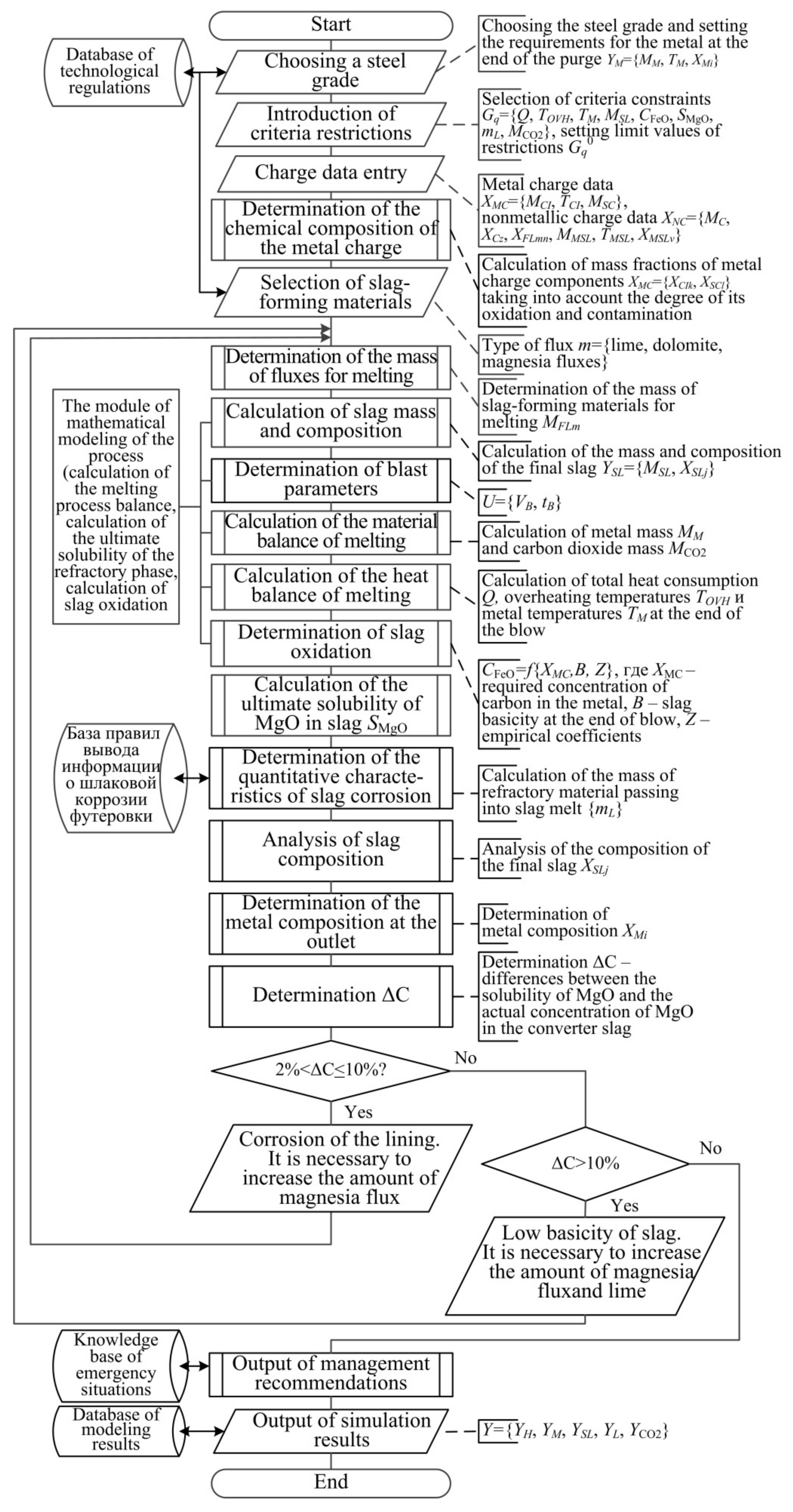
2.3. Stages of Solving the Problem of Resource and Energy Saving Control

To calculate the average residual thickness of the working lining, localization of places of increased wear, and determination of their surface area and volume, as well as calculation of the consumption of repair materials, the algorithm shown in Figure 4 is used.
At the first stage, the initial data is entered: an image of the results of laser scanning of the refractory converter lining is loaded.
The following steps are performed: normalization of the RGB values of each pixel of the image, reverse companding of the normalized RGB values, conversion of the RGB color model of each pixel into an intermediate XYZ color model, and conversion of the XYZ color model of each pixel into the CIELAB color model.
The color deviation of each pixel relative to the values of the reference shades is calculated according to Equation (1). After comparing the color deviations, a data set is formed in which each shade of color corresponds to the number of pixels found on the examined image of the refractory lining scanogram.
The obtained data set is used to calculate the average thickness of the refractory lining according to Equation (2), and the area and volume of the damaged area according to Equations (4) and (5), respectively, as well as the mass of the required repair mixture according to Equation (6).
Depending on the localization sector of the damaged lining area and the percentage of the area of increased local wear to the area of the corresponding zone (loading zone, drain, trunnions, and slag belt), the computer system outputs recommendations for choosing the type of repair: shotcrete, garnishing, or welding.
After analyzing the results of laser scanning, the calculation of the steel melting process in the converter is carried out, which is a solution of the systems of equations of material and thermal balances involved in the process of chemical elements, empirical dependencies, and ratios [18,19,22,24,26,56,57].
The solution of the system of Equations (7)–(16) includes the following main stages, which are shown in Figure 5:
  • The choice of steel grade XMi, determination of the metal mass MM, and metal temperature TM;
  • Selection and setting of criteria restrictions values, Gq = {Q, TOVH, TM, MSL, CFeO, SMgO, mL, MCO2};
  • Determination of scrap mass MSC and cast iron mass MCI, and calculation of mass fractions of chemical components of the metallic charge {XCIk, XSCl} taking into account the degree of its oxidation and contamination;
  • Determination of the mass and composition of the non-metallic charge XNC = {MC, XCz, XFLmn, MMSL, TMSL, XMSLv}, including the choice of fluxes;
  • Determination of the mass of fluxes MFLm for melting for effective neutralization of converter slag;
  • Calculation of quantity MSL and the chemical composition of the slag XSLj, formed in the process of converter melting of steel as a result of the oxidation of metallic charge impurities and the dissolution of non-metallic materials;
  • Calculation of blast parameters VB (9), tB (11);
  • Calculation of the material balance (7)–(8) and (10) of the process, including the calculation of the mass of the metal MM and the mass of carbon dioxide MCO2;
  • Calculation of the thermal balance (12)–(13) of the converter melting (determination of the total heat consumption Q, overheating temperature TOVH (15), and the temperature of the metal at the end of the purge TM (14));
  • Determination of slag oxidation (the higher the oxidation of slag, the higher its aggressiveness towards the refractory converter lining);
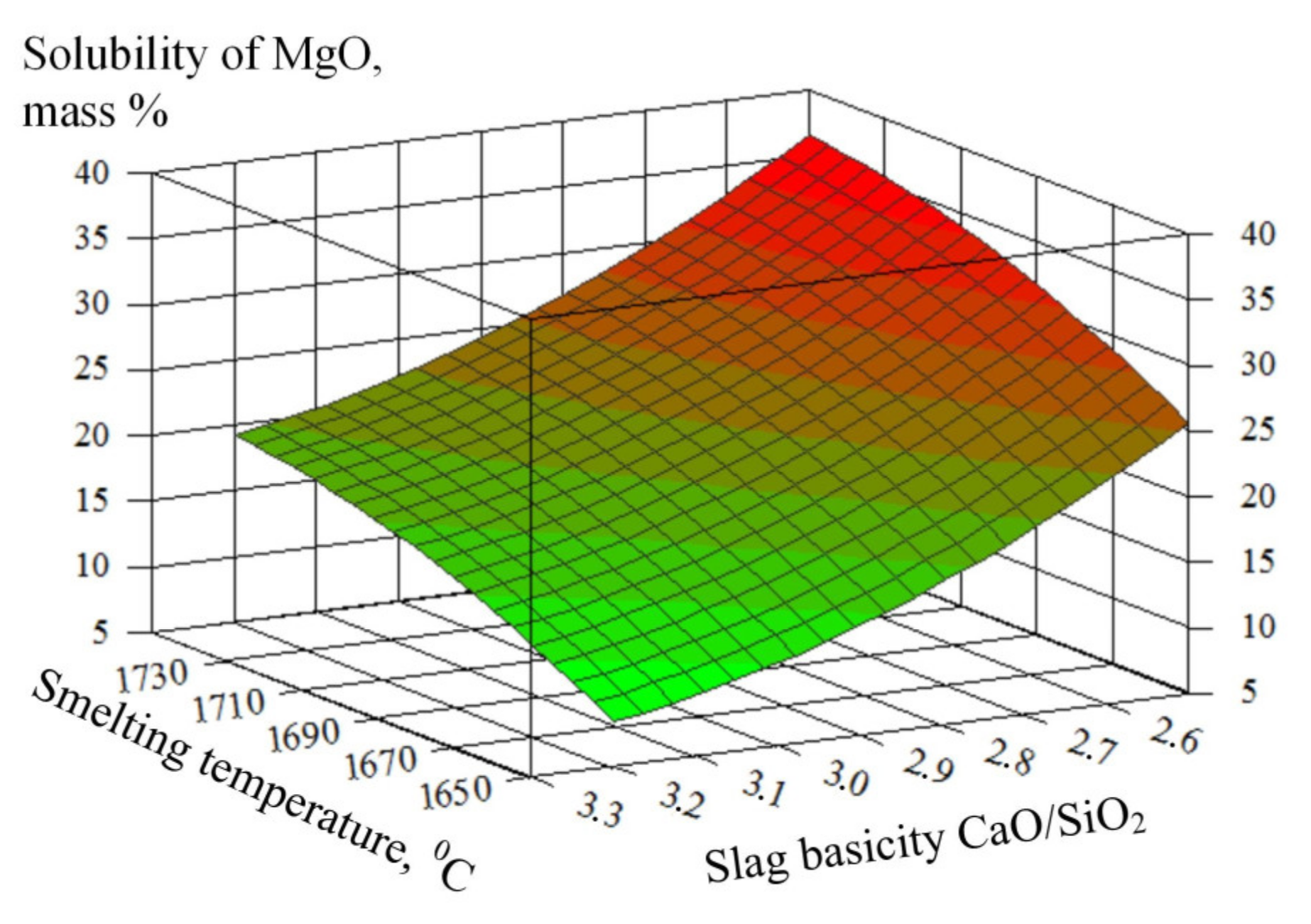
  • Determination of the ultimate solubility of the refractory phase (MgO) in the converter slag;
  • Determination of slag corrosion characteristics mL;
  • Prediction of the aggressiveness of the slag in relation to the converter lining based on the analysis of the temperature and chemical composition of the slag. To reduce the aggressiveness of the slag, its chemical composition is modified to the area of the primary crystallization of MgO, saturating the melt with magnesium oxide by using various magnesia slag-forming additives [47] (16);
  • Calculation of the metal qualitative composition YM = {XMi};
  • Slag composition analysis XSLj and its modification in order to purposefully impart the properties necessary in the production of useful products;
  • Output of simulation results and control recommendations Y = {YH, YM, YSL, YL, YCO2}.

3. Results of Testing and Practical Implementation of the System

The conducted testing of the operation of the computer system on the example of the study of the process of oxygen-converter melting of steel according to CherMF (PJSC Severstal) and PJSC NLMF confirmed its operability and the possibility of using it in the mode of the operator’s adviser at iron and steel enterprises for a comprehensive study and study of resource and energy saving process control methods, as well as making decisions on the operation refractory lining of steelmaking converters.
Figure 6 shows an example of the system interface with the results of the image analysis of the oxygen converter lining scan after 3622 melts.
The interface shows the calculated values of the surface area and volume of places of increased local wear of the lining, recommended repair methods (welding, shotcrete, and garnishing), as well as the amount of repair material. The thickness of the residual layer in places of increased wear of the lining is less than 0 mm; that is, the reinforcing refractory layer is affected, which indicates severe wear of the structure and the danger of its further operation.
Examples of source data for determining acceptable values of control actions when testing the system are shown in Table 1 and Table 2, respectively.
The results of calculating the material and thermal balances of the steel converter melting process with the given initial data are shown in Table 3, Table 4 and Table 5, respectively. The molten metal temperature at the end of blasting is 1655 °C; the overheating temperature 123 °C.
Table 6 shows the results of calculating the composition of metal and slag. In this case, the optimal consumption of fluxes is used.
With a change in the initial amount of FOM XFL FOM = 7.5 t, the value of the driving force of the process of refractory slag corrosion ΔC = 4.3%, which indicates the corrosion of the refractory lining (Table 7); thus, it is recommended to increase the amount of magnesia flux and recalculate the material balance.
Figure 7 shows the dependence of the approximate solubility of MgO on the smelting temperature and basicity of the slag (at constant oxidation FeO = 25% by mass.).
The study of the influence of the basicity and temperature of the converter slag on the ultimate solubility of MgO demonstrated that a decrease in basicity and an increase in the temperature of the converter slag leads to an increase in the MgO saturation concentration and increased slag corrosion. The dynamics of the slag corrosion is determined by the MgO saturation concentration in the converter slag, which depends on its temperature and chemical composition.
Compared with the existing results, the use of a computer system at metallurgical enterprises can increase the life of the trouble-free operation of converters by 3%, significantly reduce the time spent on processing the results of laser scanning of the working layer of refractory lining (up to 60%), improves the indicators of energy intensity of production by 3% and reducing the consumption of periclase-carbon refractory lining material, which is made from pure electromagnesia (melting temperature over 2800 °C), and also reduces the negative impact of waste on the environment (the mass of carbon dioxide released decreased by 1.5%).

4. Conclusions

A comprehensive study of the steelmaking converter process was carried out to solve the problem of resource and energy saving control, taking into account waste recycling. An analysis of literature sources and research results in the field of the energy saving of metallurgical industries [1,2,3,4,5,6,7,8,9,10], chemical technology of high-temperature materials used in thermal units [11,12,13,14,15,16,17], and modeling of steelmaking processes [18,19,20,21,22,23,24,25,26] demonstrated the need for the integrated interconnected control of energy and material resources of steelmaking industries. The paper proposes a methodology for an integrated approach to solving the resource and energy saving control problem of the steelmaking converter process by creating a computer system that allows, on the basis of a library of deterministic and empirical models, one to issue recommendations to control production personnel. The efficiency of using a computer system is to increase the life of the refractory converter lining, increase the number of melts, comply with environmental safety requirements, as well as reduce energy consumption and waste production.
The computer system allows for analyzing the condition of the refractory converter lining, predicting the composition of steel and the aggressiveness of the slag melt to slow down the wear rate of the converter lining and protect it from destruction, calculating the material and thermal balances of the melting process, calculating the permissible values of the time and volume of the blast, calculating the quantitative characteristics of slag corrosion, and determining the carbon dioxide mass, as well as the amount and composition of the resulting slag. Based on the results of calculating the material balance equations, the computer system allows one to determine the mass and composition of steel, the mass of carbon dioxide, and the mass and composition of the slag formed, and according to the results of calculating the heat balance equations, the total heat consumption, the overheating temperature and the temperature of the metal at the end of purging.
The quantity, chemical composition, viscosity, and rate of slag formation have a significant impact on the quality of steel, and the yield of usable metal, as well as on slag wear of the refractory converter lining. The negative effect of the converter slag is a corrosive destructive effect on the refractory converter lining. The amount and composition of the formed slag is determined by the consumption of slag-forming materials, the composition of the metallic charge, the metal indicators at the end of purging, and the required basicity of the slag. Determining the permissible composition of converter slag is important not only to reduce the wear of the refractory converter lining, but also for further use as a secondary raw material for the production of new useful products; for example, in the production of crushed stone used in road construction, as well as in an iron-containing material for the secondary remelting in blast furnaces.
The dataware of the computer system, by changing the ranges of the parameters X, is configured for various operating modes of the control object U, which ensures the adaptation of the system and its integration into automated systems for the design and control of steelmaking technological processes and productions.
The validation of the software modules of the computer system was verified using functional testing by the black box method on various sets of source data provided by the leading Russian enterprises CherME (PJSC Severstal) and PJSC NLMK. The adequacy and operability of the mathematical models is verified by the statistical processing of the calculated and measured values using the Fisher criterion. The calculated values of the Fisher criterion F and the coefficient of determination R2 exceed their tabulated values; therefore, the mathematical models of the converter process proposed in the paper are adequate to a real object with a confidence probability of 0.95.
The results obtained can be used by international metallurgical enterprises to solve the resource and energy saving control problems of the steelmaking converter processes, taking into account waste processing. The use of a computer system ensures an increase in the number of melts in the converter and improvement of waste capacity indicators, as well as the energy and resource conservation of steelmaking processes, which is a key direction of the international metallurgical industry.

Author Contributions

Conceptualization, T.C. and A.S.; methodology, T.C.; software, I.N. and V.K.; validation, I.N. and V.K.; formal analysis, T.C.; investigation, T.C, I.N., and V.K.; resources, A.S.; data curation, V.K.; writing—original draft preparation, I.N.; writing—review and editing, T.C.; visualization, V.K.; supervision, A.S.; project administration, T.C.; funding acquisition, A.S. and T.C. All authors have read and agreed to the published version of the manuscript.

Funding

The research was conducted at the expense of a grant from the Russian Science Foundation (project No. 21-79-30029 Development of a complex of technologies for recycling waste of hazard classes 3–5 with the production of useful products).

Data Availability Statement

Not applicable.

Conflicts of Interest

The authors declare no conflict of interest.

References

  1. Danilov, N.; Silin, V.; Dobrodey, V.; Popov, V. Energy Problems of the Rational Use of the Economic Potential of the Region; WIT Press: Billerica, MA, USA, 2014; Volume 190, pp. 419–423. [Google Scholar] [CrossRef] [Green Version]
  2. Pavlov, A.; Spirin, N.; Beginyuk, V.; Lavrov, V.; Gurin, I. Analysis of slag mode of blast furnace melting using model decision support systems. Izv. Ferr. Metall. 2022, 65, 413–420. [Google Scholar] [CrossRef]
  3. Lisienko, V.G.; Malikov Yu, K.; Titaev, A.A.; Khodakov, E.V. Safe and Energy-efficient Thermal Modes of the Mine Air Heating Systems. Occup. Saf. Ind. 2022, 2, 81–87. [Google Scholar] [CrossRef]
  4. Lisienko, V.; Shchelokov, Y.; Lapteva, A. Energy benefits of the coke-free production of ferrous metals. Steel Transl. 2008, 38, 733–738. [Google Scholar] [CrossRef]
  5. Kazarinov, L.; Barbasova, T.; Rozhko, E. A Method for Stabilizing Blast Furnace Process Thermal State. In Proceedings of the International Russian Automation Conference (RusAutoCon), Sochi, Russia, 5–11 September 2021. [Google Scholar] [CrossRef]
  6. Kolesnikova, O.; Kazarinov, L.; Prosoedov, R. Automation of Steam Boiler Load Regulation at the Electric Power Station of an Iron and Steel Enterprise. In Proceedings of the 2019 IEEE Russian Workshop on Power Engineering and Automation of Metallurgy Industry: Research & Practice (PEAMI), Magnitogorsk, Russia, 4–5 October 2019; pp. 110–115. [Google Scholar] [CrossRef]
  7. Giampieri, A.; Roy, S.; Vijayalakshmi, S.K.; Smallbone, A.; Roskilly, A.P. An integrated smart thermo-chemical energy network. Renew. Sustain. Energy Rev. 2022, 16, 112869. [Google Scholar] [CrossRef]
  8. Mohapatra, J.; Kumar, D.S. Advances in Automobile Engineering Dual Stabilization Heat Treatment in a TRIP Assisted Steel to Realize Third Generation. Adv. High Strength Steel Prop. 2022, 11, 1–6. [Google Scholar] [CrossRef]
  9. Hao, J.; Wu, R.; Zhou, J.; Zhou, Y.; Jiang, L. Regulation of bioinspired ion diodes: From fundamental study to blue energy harvesting. Nano Today 2022, 46, 101593. [Google Scholar] [CrossRef]
  10. Pitkälä, J.; Holappa, L.; Jokilaakso, A. A Study of the Effect of Alloying Elements and Temperature on Nitrogen Solubility in Industrial Stainless Steelmaking. Metall. Mater. Trans. B 2022, 53, 2364–2376. [Google Scholar] [CrossRef]
  11. Kozlov, V.V.; Shevchik, A.P.; Suvorov, S.A.; Arbuzova, N.V.; Kuznetsov, D.V. Modeling of the Phase Composition of Refractory and Slag Systems, Optimization of Slag Adjustment, and Stabilization of Secondary Steelmaking Slags. Refract. Ind. Ceram. 2019, 59, 502. [Google Scholar] [CrossRef]
  12. Borovik, S.; Lysova, G.; Chuklai, A. Kinetic Aspects of the Thermal Degradation of a Temporary Binder Modified with Vitreous Molasses for Use in Making High-Temperature Periclase Refractories. Refract. Ind. Ceram. 2014, 54, 479–484. [Google Scholar] [CrossRef]
  13. Metelkin, A.; Sheshukov, O.; Saveliev, M.; Shevchenko, O.; Egiazaryan, D.; Nekrasov, I.; Tkachev, A.; Elin, V. Optimization of the Slag Conditions in a Ladle Furnace. Metallurgist 2022, 66, 1–4. [Google Scholar] [CrossRef]
  14. Aneziris, C.G.; Hubálková, J.; Barabás, R. Microstructure Evaluation of MgO–C Refractories With TiO2- and Al-Additions. J. Eur. Ceram. Soc. 2007, 27, 73–78. [Google Scholar] [CrossRef]
  15. Sadrnezhaad, S.K.; Mahshid, S.; Hashemi, B.; Nemati, A. Oxidation Mechanism of C in MgO–C Refractory Bricks. J. Am. Ceram. Soc. 2006, 89, 1308–1316. [Google Scholar] [CrossRef]
  16. Hocquet, S.; André, S.; Erauw, J.-P.; Tirlocq, J.; Cambier, F. Characterisation of oxidation phenomena in carbon containing refractory materials for metallurgy. In Proceedings of the Unified International Technical Conference on Refractories, Dresden, Germany, 18–21 September 2007; pp. 226–229. [Google Scholar]
  17. Di Cecca, C.; Barella, S.; Mapelli, C.; Gruttadauria, A.; Ciuffini, A.; Mombelli, D.; Bondi, E. Thermal and chemical analysis of massive use of hot briquetted iron inside basic oxygen furnace. J. Iron Steel Res. Int. 2017, 24, 901–907. [Google Scholar] [CrossRef]
  18. Shapovalov, A.N. Tekhnologiya i Raschet Plavki Stali v Kislorodnykh Konverterakh [Technology and Calculation of Steel Smelting in Oxygen Converters]; MISiS: Novotroitsk, Russia, 2011. (In Russian) [Google Scholar]
  19. Korneeva, A.; Kornet, M. Nonparametric modeling of oxygen-converter steelmaking. Izv. Vyss. Uchebnykh Zavedenij. Chernaya Metall. 2015, 56, 24. [Google Scholar] [CrossRef] [Green Version]
  20. Korneeva, A.A.; Medvedev, A.V.; Raskina, A.V. About nonparametric dual control algorithm. In Proceedings of the Systems Analysis: Modeling and Control Abstracts of the International, Institute of Mathematics and Mechanics of the Ural Branch of RAS, Yekaterinburg, Russia, Conference in Memory of Academician Arkady Kryazhimskiyeas, Yekaterinburg, Russia, 3–8 October 2016; pp. 69–71. [Google Scholar]
  21. Kornet, M.; Raskina, A.; Korneeva, A.; Videnin, S.; Masich, I. Non-parametric algorithms of identification and control of group of technological processes in low-carbon steel production. J. Phys. Conf. Ser. 2020, 1679, 042042. [Google Scholar] [CrossRef]
  22. Grigorovich, K.V.; Komolova, O.A. Mathematical modeling and optimization of steelmaking technologies. In Proceedings of the ICS 2018—7th International Congress on Science and Technology of Steelmaking: The Challenge of Industry 4.0, Venice, Italy, 13–15 June 2018. [Google Scholar]
  23. Kolesnikov, Y.; Bigeev, V.; Sergeev, D. Modeling of steelmaking in bof based on physical, chemical and thermal processes. Izv. Vyss. Uchebnykh Zaved. Chernaya Metall. 2017, 60, 698–705. [Google Scholar] [CrossRef] [Green Version]
  24. Wen, D.; Zhu, Y. Research on Prediction of Oxygen Consumption in Converter Steelmaking Based on IGWO-SVM Model. J. Phys. Conf. Ser. 2021, 2010, 012138. [Google Scholar] [CrossRef]
  25. Cao, L.; Wang, Y.; Liu, Q.; Feng, X. Physical and Mathematical Modeling of Multiphase Flows in a Converter. ISIJ Int. 2018, 58, 573–584. [Google Scholar] [CrossRef] [Green Version]
  26. Lu, B.H.; Li, Y.K.; Qu, B.Z. Optimization Research on Converter Steelmaking Process Parameters Based on DOE. Key Eng. Mater. 2013, 579–580, 128–132. [Google Scholar] [CrossRef]
  27. Meshalkin, V. Main Directions of Engineering Theory of Energy and Resource Efficient Chemical-Technological Systems in the Conditions of Digital Economy; Russian Academy of Sciences: Moscow, Russia, 2021; pp. 34–42. [Google Scholar] [CrossRef]
  28. Filimonova, A.A.; Barbasova, T.A. Automated system for simulation of electricity consumption in the iron and steel plant. In Proceedings of the 2017 International Conference on Industrial Engineering, Applications and Manufacturing (ICIEAM), Chelyabinsk, Russia, 16–19 May 2017; pp. 1–4. [Google Scholar] [CrossRef]
  29. Nolde, K.; Morari, M. Electric load tracking scheduling of a steel plant. Comput. Chem. Eng. 2010, 34, 1899–1903. [Google Scholar] [CrossRef] [Green Version]
  30. Meshalkin, V.; Dovì, V.; Bobkov, V.; Belyakov, A.; Butusov, O.; Garabadzhiu, A.; Burukhina, T.; Khodchenko, S. State of the art and research development prospects of energy and resource-efficient environmentally safe chemical process systems engineering. Mendeleev Commun. 2021, 31, 593–604. [Google Scholar] [CrossRef]
  31. Dvoretskii, D.S.; Dvoretskii, S.I.; Ostrovskii, G.M. Integrated design of power- and resource-saving chemical processes and process control systems: Strategy, methods, and application. Theor. Found. Chem. Eng. 2008, 42, 26–36. [Google Scholar] [CrossRef]
  32. Meshalkin, V.; Chelnokov, V.; Makarenkov, D. Methods of Digital Engineering of Resource Energy-Saving Environmentally Safe Chemical Process Systems. Vestn. Tambov. Gos. Teh. Univ. 2021, 27, 564–575. [Google Scholar] [CrossRef]
  33. The World Steel Association (Worldsteel). Available online: https://www.worldsteel.org/ (accessed on 24 January 2023).
  34. Meshalkin, V.P.; Butusov, O.B.; Dovi, V.G.; Belozerskii, A.Y.; Chelnokov, V.V. Assessment of the Impact of the Chemical Pollution due to Metallurgical Plants on Forest Areas Using Satellite Images. Steel Transl. 2021, 51, 783–787. [Google Scholar] [CrossRef]
  35. Fan, Z.; Friedmann, S. Low-carbon production of iron and steel: Technology options, economic assessment, and policy. Joule 2021, 5, 829–862. [Google Scholar] [CrossRef]
  36. Makarova, A.; Tarasova, N.; Meshalkin, V.; Kukushkin, I.; Kudryavtseva, E.; Kantyukov, R.; Reshetova, E. Analysis of the management system in the field of environmental protection of russian chemical companies. Int. J. Qual. Res. 2018, 12, 43–62. [Google Scholar] [CrossRef]
  37. Holappa, L.; Kekkonen, M.; Jokilaakso, A.; Koskinen, J. A Review of Circular Economy Prospects for Stainless Steelmaking Slags. J. Sustain. Metall. 2021, 7, 806–817. [Google Scholar] [CrossRef]
  38. Heikkinen, E.; Leinonen, V.; Tanskanen, P.; Fabritius, T. A Computational study to estimate the possibilities to improve utilisation of stainless steelmaking slags. Calphad 2021, 75, 102349. [Google Scholar] [CrossRef]
  39. Salman, M.; Dubois, M.; Di Maria, A.; Van Acker, K.; Van Balen, K. Construction Materials from Stainless Steel Slags: Technical Aspects, Environmental Benefits, and Economic Opportunities. J. Ind. Ecol. 2016, 20, 854–866. [Google Scholar] [CrossRef]
  40. Rosales Garcia, J.; Agrela, F.; Entrenas, J.; Cabrera, M. Potential of Stainless Steel Slag Waste in Manufacturing Self-Compacting Concrete. Materials 2020, 13, 2049. [Google Scholar] [CrossRef]
  41. Sheen, Y.-N.; Le, D.-H.; Sun, T.-H. Innovative usages of stainless steel slags in developing self-compacting concrete. Constr. Build. Mater. 2015, 101, 268–276. [Google Scholar] [CrossRef]
  42. Protopopov, E.; Kuznetsov, S.; Feiler, S.; Ganzer, L.; Kalinogorsky, A. Converter steelmaking process: State, dominant trends, forecasts. IOP Conf. Ser. Mater. Sci. Eng. 2018, 411, 012002. [Google Scholar] [CrossRef] [Green Version]
  43. Yaroshenko, A.V.; Dagman, A.I.; Berestyukov, Y.e.V.; Nekrasov, I.A. Opyt Novolipetskogo metallurgicheskogo kombinata v razvitii konverternogo proizvodstva [Experience of the Novolipetsk Steel in the development of a converter production]. Ferr. Metall. 2013, 4, 43–48. (In Russian) [Google Scholar]
  44. Luk’yanov, A.V.; Protasov, A.V.; Sivak, B.A.; Shchegolev, A.P. Making BOF Steelmaking More Efficient Based on the Experience of the Cherepovets Metallurgical Combine. Metallurgist 2016, 60, 248–255. [Google Scholar] [CrossRef]
  45. Jalkanen, H.; Holappa, L. Chapter 1.4. Converter Steelmaking. Treatise Process Metall. 2013, 3, 223–270. [Google Scholar] [CrossRef]
  46. Díaz, J.; Fernández, F.J. The impact of hot metal temperature on CO2 emissions from basic oxygen converter. Environ. Sci. Pollut. Res. 2020, 27, 33–42. [Google Scholar] [CrossRef]
  47. Demidov, K.; Shatilov, O.; Lamukhin, A.; Zinchenko, S.; Babenko, A.; Dmitrienko, Y.; Borisova, T.; Sarychev, B.; Ovsyannikov, V.; Voronina, O. Improving Lining Resistance Using High-Magnesia Fluxes in the Converter Steelmaking Process. Refract. Ind. Ceram. 2003, 44, 13–16. [Google Scholar] [CrossRef]
  48. Wedrychowicz, M.; Bydałek, A.W.; Basiura, B. Analysis of slag activity on corrosion of ceramic materials in a slurry furnace. Arch. Foundry Eng. 2018, 18, 95–100. [Google Scholar] [CrossRef]
  49. Sheshukov, O.; Nekrasov, I.; Mikheenkov, M.; Egiazar’yan, D.; Ovchinnikova, L.; Zemlyanoi, K.; Zemlyanoi, K.; Kamenskikh, V. Effect of Refining Slag Phase Composition on Ladle Furnace Unit Lining Life1. Refract. Ind. Ceram. 2016, 57, 109–116. [Google Scholar] [CrossRef]
  50. Zemlyanoi, K.; Zemlyanoi, K.; Chevychelov, A.; Valuev, A.; Pomortsev, S. Periclase-Carbon Refractories Molded by a New Method1. Refract. Ind. Ceram. 2017, 58, 145–147. [Google Scholar] [CrossRef]
  51. Amelin, A.; Protopopov, E.; Kuznetsov, S.; Kalinogorskii, A.; Ganzer, L. Characteristic Features of the Gas Injection Process in Oxygen Converters That Use Iron-Containing Slag Produced During Steel Smelting. Metallurgist 2019, 63, 549–552. [Google Scholar] [CrossRef]
  52. Kozlov, V.; Shevchik, A.; Suvorov, S.; Ivanov, A.; Arbuzova, N.; Pogodina, K. Calculated and Experimental Determination of the Phase Composition of Extra-Furnace Steel Treatment Slags. Refract. Ind. Ceram. 2020, 60, 459–462. [Google Scholar] [CrossRef]
  53. Sheshukov, O.Y.; Nekrasov, I.V.; Mikheenkov, M.A.; Egiazar’yan, D.K.; Lobanov, D.A. Stabilization of Refining Slag by Adjusting Its Phase Composition and Giving It the Properties of Mineral Binders. Refract. Ind. Ceram. 2017, 58, 324–330. [Google Scholar] [CrossRef]
  54. Aksel’rod, L.; Maryasev, I.; Platonov, A. Method of Determining the Resistance of Furnace Refractories to Slag and Clinker. Refract. Ind. Ceram. 2013, 54, 135–140. [Google Scholar] [CrossRef]
  55. Chistyakova, T.B.; Novozhilova, I.V. Methods and Technologies of Computer Training Complexes Design for Personnel in Metallurgical Production Control. In Proceedings of the 2018 Third International Conference on Human Factors in Complex Technical Systems and Environments (ERGO)s and Environments (ERGO), St. Petersburg, Russia, 4–7 July 2018; pp. 132–136. [Google Scholar] [CrossRef]
  56. Galkin, A.; Sysoev, A.; Saraev, P. Variable structure objects remodelling based on neural networks. In Proceedings of the 2017 International Conference on Industrial Engineering, Applications and Manufacturing (ICIEAM), St. Petersburg, Russia, 16–19 May 2017; pp. 1–4. [Google Scholar] [CrossRef]
  57. Chistyakova, T.B.; Novozhilova, I.V.; Kozlov, V.V. Computer System of Industrial Data Mining for Resource-Saving Control of Steel-Smelting Converter Production. In Proceedings of the 2019 1st International Conference on Control Systems, Mathematical Modelling, Automation and Energy Efficiency (SUMMA), Lipetsk, Russia, 20–22 November 2019; pp. 523–526. [Google Scholar] [CrossRef]
Figure 1. A scan of the refractory lining. 1—The zone of the slag belt; 2—Loading zone; 3—Drain area; 4—Trunnion zones.
Energies 16 01302 g001
Figure 2. Formalized description of the process of converter melting of steel as a control object.
Energies 16 01302 g002
Figure 3. Functional structure of a computer system.
Energies 16 01302 g003
Figure 4. Block diagram of the algorithm for analyzing the scans of refractory lining.
Energies 16 01302 g004
Figure 5. Block diagram of the algorithm for solving the converter process control problem.
Energies 16 01302 g005
Figure 6. The results of the analysis of the image of the scan after 3622 melts.
Energies 16 01302 g006
Figure 7. Dependence of the solubility of MgO in converter slag on the smelting temperature and basicity (at constant oxidation of slag FeO = 25 mass %).
Energies 16 01302 g007
Table 1. Initial data on the scrap and cast-iron chemical composition.
Name of the
Component
Chemical Composition, %Mass, tTemperature, °C
SiMnCPS
Scrap0.20.050.10.40.04110
Cast iron0.60.74.00.150.0252901440
Table 2. Initial data on the fluxes’ chemical composition.
Name of the FluxFluxes’ Chemical CompositionMass, t
CaOSiO2MgOFe2O3FeOMnOAl2O3CaCO3MgCO3
Lime953100001015
Dolomite32322000026172
Bauxite5105010070000.5
FOM112780700205
Table 3. Melting material balance.
Name of the ComponentMass, t
Molten metal360.327
Slag51.979
Gas30.156
Excess blast2112
Takeaways and outliers8.0
Iron losses with dust3025
Total455.599
Table 4. Calculation results of the formation of gaseous melting products.
Source of ReceiptCOCO2Total
Carbon oxidation23.8804.18628.048
Decomposition of CaCO30.4770.477
Afterburning of the CO part–23883.7531365
Decomposition of MgCO30.2670.267
Total, kg21.4928.66430.156
Total, m317.1944.41121.605
Gas composition, %0.7130.287100.000
Table 5. Heat balance of melting.
The Arrival of HeatHeat Consumption
Input ItemskJ%Output ItemskJ%
Physical heat of liquid cast iron375,231,00051.37Physical heat of molten metal523,112,72671.61
Thermal effect of oxidation reactions270,471,08037.03Physical heat of slag93,430,80612.78
Chemical heat of formation of iron oxides of slag62,952,1658.62The cost of heat for the decomposition of iron oxides1,371,5900.19
Thermal effect of slag formation reactions17,035,5962.32Physical heat of the exhaust gases72,464,4809.92
Afterburning heat of CO4,823,7600.66Heat losses with outflows and emissions10,854,4001.49
Heat costs for dust formation5,220,0130.72
Heat on the decomposition of carbonates2,144,1780.29
Heat losses21,915,4083.00
Total730,513,601100Total730,513,601100
Table 6. Results of calculation of metal and slag composition.
Name of the IndicatorCalculated DataIndustrial Data
Chemical composition of the metal XMi, % mass.C0.050.054
Si0.0040.004
Mn0.080.069
S0.0240.016
P0.0090.005
Chemical composition of the final slag XSLj,
% mass.
CaO38.9539.2
SiO211.8111.0
MgO12.2113.6
FeO29.6529.3
Al2O32.912.6
MnO3.453.0
P2O50.760.66
S0.0770.073
Table 7. The results of testing the computer system with a given amount of 7.5 tons of FOM.
Parameter IdentifierParameter ValueUnits of MeasurementResult
CaO/SiO23.3%Lining corrosion. Increase the amount of magnesia flux by 50 kg
tM1650°C
C M g O 9.3%
C M g O 13.6%
C4.3%
Disclaimer/Publisher’s Note: The statements, opinions and data contained in all publications are solely those of the individual author(s) and contributor(s) and not of MDPI and/or the editor(s). MDPI and/or the editor(s) disclaim responsibility for any injury to people or property resulting from any ideas, methods, instructions or products referred to in the content.

