
An Overview of Flexible Current Control Strategies Applied to LVRT Capability for Grid-Connected Inverters


1
Grupo de Investigación GISEL, Universidad Industrial de Santander—UIS, Bucaramanga 680001, Colombia
2
Colombian Navy, Bogotá 110110, Colombia
3
Group of Research in Electrical Engineering of Nancy (GREEN), Université de Lorraine, F-54000 Nancy, France
*
Author to whom correspondence should be addressed.
Energies 2023, 16(3), 1052; https://doi.org/10.3390/en16031052
Submission received: 30 November 2022
/
Revised: 4 January 2023
/
Accepted: 12 January 2023
/
Published: 18 January 2023
(This article belongs to the Special Issue Advances in Power System Analysis and Control)
Abstract
:Distributed power generation plays a critical role in the stability and reliability of modern power systems. Due to the rapid growth of renewable energy generation, the requirements of the transmission and distribution system operators are becoming more stringent. Among these requirements, one of the most important is the Low-Voltage Ride-Through (LVRT) capability, which demands that the inverters remain connected to the grid and provide support during voltage sags. For this purpose, flexible current control algorithms stand out because they can manage unbalanced voltages and simultaneously achieve other control objectives. With the aim of presenting a concrete document focused on describing fundamental principles and discussing common design guidelines, this paper presents an overview of flexible current control strategies applied to LVRT capability. The operation features and design aspects of experiences reported in the literature are reviewed. Moreover, the paper proposes a general methodology to design LVRT flexible current control algorithms. Finally, current and future trends are discussed.
1. Introduction
Over the last decade, there has been a growing penetration of renewable generation systems into the grid due to environmental factors and the decrease in their costs [1,2,3]. These systems include photovoltaic arrays, wind turbines, and fuel cells, among others. However, the large integration of distributed power generation systems (DPGS) can have a negative impact on the stability and reliability of power systems [4,5,6]. As a result, several countries have upgraded their grid codes (GCs) to regulate the interconnection of DPGS to the grid [7,8,9,10]. A critical GC requirement is the Low-Voltage Ride-Through (LVRT) capability, which states that the DPGS shall remain connected to the grid during a voltage sag to avoid sudden tripping and loss of power generation [11,12,13,14]. In this sense, voltage support is the main goal of the LVRT capability [15]. The aim is to recover the voltage level as much and as quickly as possible.
For a suitable LVRT control action, general criteria establish that the sag has to be quickly detected, and the full power capacity of the inverter must be exploited [16,17]. In addition, three variables are considered critical for the safety of the inverter: (1) maximum AC output current, (2) maximum AC output voltage, and (3) maximum DC-link voltage [18]. Therefore, the voltage support must be performed, limiting these parameters to safe operation points. Furthermore, grid codes requirements such as the minimum value of injected currents and the maximum voltage level at the Point of Common Coupling (PCC) must be considered. Other secondary objectives, such as minimizing voltage oscillations on the DC-link and reducing harmonic content on the injected currents, are also desirable. Among the alternatives of control strategies to execute voltage support, flexible current control algorithms have drawn attention for their capacity to achieve more than one control objective simultaneously [19,20,21,22]. Based on the p-q power theory, flexible current control algorithms decompose unbalanced fault voltages in symmetric sequences on the frame, allowing the regulation of the amount of active and reactive powers injected through the positive and negative sequences [23].
Many proposals of flexible control have been presented, which are characterized by improving operational performance using more complex control strategies. In the specialized literature, some papers as [24,25] present reviews of control techniques under different grid faults scenarios. However, considering that these works present a broad view of this application, the discussion of the specific characteristics and potentials of flexible control for LVRT operation is very limited.
Thus, motivated by the aforementioned, this paper presents an overview of flexible current control applied to the LVRT capability. The overview includes an analysis of the concepts and theory which constitute the flexible control fundamental principles. Regarding the design stage, general recommendations are given, according to the experiences reported in the literature. This is complemented with a discussion of current and future trends. Finally, the paper proposes a generalizable methodology to design flexible current control algorithms prioritizing the voltage support strategy. The main goal of this work is to offer researchers and designers a clear and concrete document focused on presenting and discussing LVRT flexible control strategies from their foundation, operation features, design aspects, and possible future developments.
The rest of the paper is organized as follows. Section 2 presents the fundamental concepts of LVRT capability operation. The power converter system and its control structure are described in Section 3. In Section 4, the operational features of flexible current control are reviewed and discussed. A description of the current state of art is performed in Section 5. Section 6 introduces the proposed generalizable methodology to design flexible current control algorithms. Section 7 discusses the most important aspects of the previous sections with the aim of identifying future research trends. Finally, conclusions are drawn in Section 8.
2. LVRT Considerations
The growth in the penetration of grid-connected DPGS has led to changes in the ancillary services required by the GCs in order to guarantee the stability and reliability of distribution systems. To better understand the operation of DPGS during grid faults, this section presents the main aspects of voltage sags, reviews LVRT requirements in different GCs, and discusses some common strategies for voltage support.
2.1. Voltage Sags
A voltage sag is a short-time reduction in the RMS voltage value of one or more grid phases. They can be caused by short circuits, overloads, and the starting of large motors. Table 2 of IEEE Std 1159 categorizes different electromagnetic phenomena, including voltage sags [26]. According to this standard, the magnitude of typical voltage sags is between 0.1 and 0.9 V. Nevertheless, some grid codes consider LVRT profiles from 0 to 0.9 V (e.g., the German code). Although magnitude and duration are the main characteristics of voltage sags, other features such as phase angle jumps and unbalance must be considered [27]. In fact, the occurrence of symmetrical faults is rare (close to 2–3% overall [28]). Therefore, most grid faults are asymmetrical, generating negative and zero sequence voltages in the network [29,30].
2.2. Grid Code Requirements
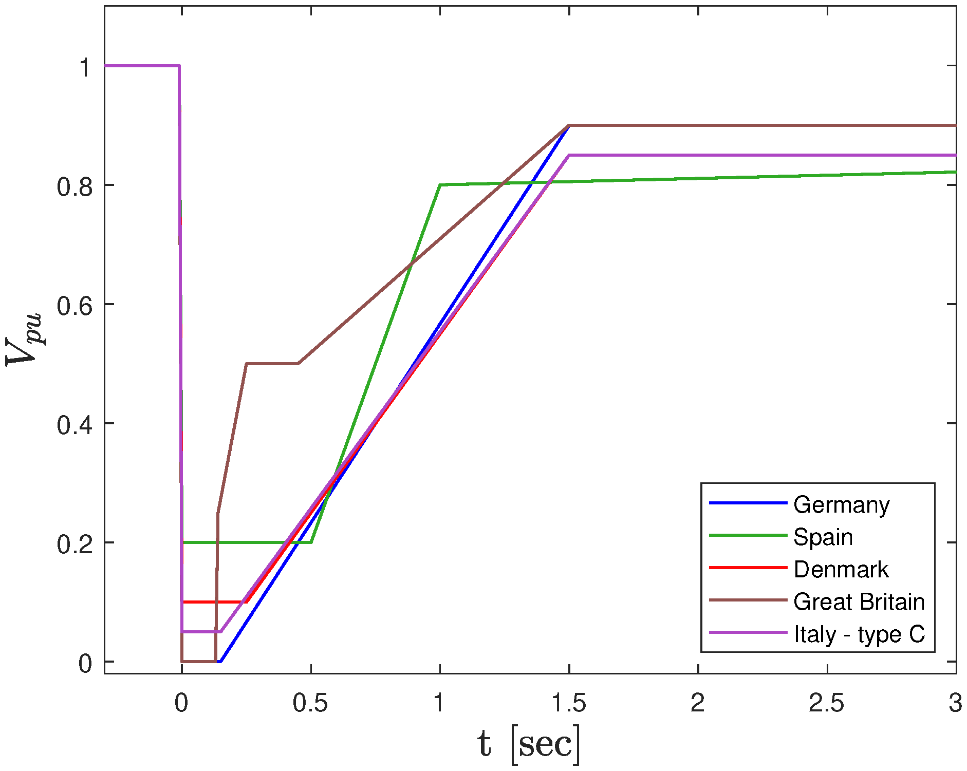
GCs are a collection of technical specifications to coordinate the operation and integration of different power generators to the grid. They are imposed by the transmission and distribution system operators seeking to guarantee the stability and regulation of the system frequency and voltage [31,32]. Over the last decade, the DPGS requirements have become more stringent in many countries due to the considerable rise in renewable energy generation [33]. In this sense, GCs usually require the DPGS to stay connected to the grid during voltage sags. Moreover, maximum current and reactive current injection (RCI) are requested in order to support the voltage recovery. Once the fault is cleared, the DPGSs must resume active power supply [34]. A voltage vs. fault duration profile is defined to consider the safety of the equipment. Figure 1 shows the profiles of different national GCs. Disconnection is allowed for voltages below these profiles [33,35].
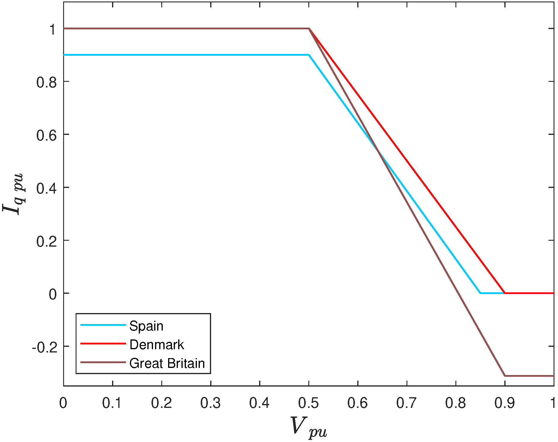
In the same way, some GCs define a minimum RCI profile to provide voltage support, as shown in Figure 2 [35,38]. However, this requirement is based on the assumption that grid impedance is mainly inductive, which is not always valid (e.g., low-voltage microgrids have a mainly resistive impedance). In fact, many authors have found that the grid impedance must be taken into account to optimize the voltage support [39,40,41]. Another feature to mention is that some GCs determine the RCI requirement considering the on-grid voltage reduction during the fault and the nominal power and current of the source, e.g., GCs of Germany and Colombia [42,43].
2.3. Voltage Support Strategies and Secondary Objectives
Modern GCs must be adapted to overcome the challenge that the massive integration of renewable energies will pose to the power quality of electrical systems [46]. For instance, the suitable characterization of the grid impedance and the voltage support strategy selection play a relevant role in the voltage recovery. Camacho et al. has proposed three basic approaches of voltage support strategies: the first is an approach in which the positive sequence voltage support is maximized [41]. In this case, all the phase voltages are raised equally by injecting active and reactive power only through the positive sequence. However, unfaulted phases can present a troublesome over-voltage due to the unbalance [47]. The second is an approach in which the negative sequence voltage is minimized to reduce the unbalance between phases. Therefore, it is necessary to consume active power through the negative sequence, which is the major inconvenience of this strategy since a backup (EES) or an element to dissipate the power is required. The third is an approach that combines the two mentioned methods, and its goal is to maximize the difference between the positive and negative sequence voltages. According to Camacho et al., this strategy is the most convenient to restore the voltages to the values prior to the occurrence of the fault [41]. Other control proposals have focused on maximizing the power delivered and the injection of currents, which result in a non-controlled voltage support [19,21,46].
In addition to the voltage support, other LVRT secondary objectives such as minimizing the DC-link voltage oscillations, reducing harmonic components on injected currents, and mitigating power oscillations are also desired [48,49,50,51,52]. To improve the inverter performance, achieving these secondary objectives is not a simple task, since the three main system restrictions must be considered: (1) maximum phase current limit, (2) maximum phase voltage limit, and (3) maximum DC-link voltage limit [18]. In addition, there are regulatory restrictions such as the minimum amount of injected current, LVRT voltage profiles, and the maximum phase voltage allowed by the GC [46,47]. Furthermore, the LVRT control strategy should also consider the type and severity of the fault, the grid characteristics, and the power generation and power curtailment scenarios. For these reasons, it is a common practice to organize the secondary objectives in a hierarchical control structure [34].
3. System Description
This section presents a general model of a grid-connected inverter and its control scheme. Moreover, the role and contribution of each control loop for the LVRT capability is analyzed.
3.1. Grid-Connected Inverter
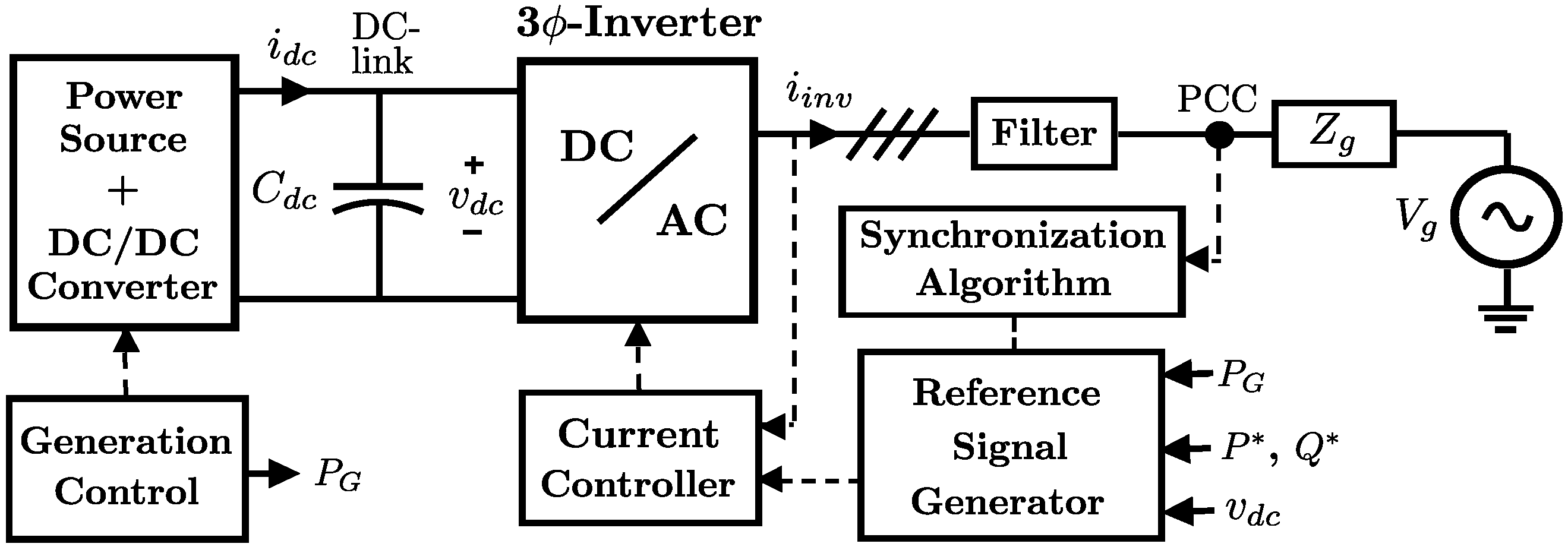
Figure 3 shows a general schematic of a grid-connected inverter. The DC stage comprises the power source (renewable generation or storage systems). An optional DC-DC converter is mainly used to manage the voltage level and control the generated power [53]. A DC-link capacitor is used to balance the power exchange between the inverter and the DC-stage. A filter is implemented at the output of the three-phase inverter to reduce the high-frequency harmonics [54,55]. The grid effect is usually modeled with a line impedance and a voltage source . Although not included in the scheme, some loads could be connected at the PCC, and may include the impedance of a power transformer between the inverter and the grid.
3.2. Control Loops
The main control loops of the system are shown in Figure 3. Briefly, during fault conditions, the reference current must be calculated to improve the voltage support while complying with the system restrictions. The synchronization algorithm estimates the grid frequency and the symmetric components of the PCC voltages [56,57,58,59]. The current controller tracks the reference signal and generates the pulses for the inverter [60,61]. The generation control manages the power production at the renewable source.
According to the general criteria of the specialized literature, employing the full inverter capacity and a fast response are desired. It can be established that the synchronization algorithm and the current controller are mainly related to the reaction time of the inverter. One is responsible for sensing and obtaining the information of the PCC fault voltages, and the other implements the control’s actions through the inverter switching. On the other hand, generation control and reference current algorithms are responsible for exploiting the inverter’s full capacity. Section 4 shows the benefits of using flexible current algorithms to generate the reference signal. As for the generation control, the goal is to produce the maximum amount of power under normal operation. However, power curtailment could be required during fault conditions due to the current limit of the inverter. In this case, the generation control could be operated in a non-MPPT mode to maintain the power balance between the injected power and the power source [22,52].
4. Flexible Current Control Algorithms
Flexible current algorithms are selected for the calculation of current reference signals during voltage sags, since these allow the injection of different amounts of active and reactive powers via positive and negative sequences [21]. Moreover, the flexible approach allows the manipulation of the power loops to avoid distorted currents and cancel power oscillations as well as other operational features.
4.1. Basic Formulation
First, some basic definitions are presented in order to state some principles of the flexible current control. For this strategy, the PCC voltages are decomposed in symmetric sequences on the frame, as shown in (1), where , , , and are the amplitudes and phases of the positive- and negative-sequences voltages and is the grid angular frequency [23,34]. Moreover, the instantaneous active power p and the instantaneous reactive power q are defined by (2) according to the p-q theory [62,63].
4.2. Fundamental Concepts of Flexible Control
The main characteristic of a flexible strategy is the ability to modify the control algorithm using scalar factors to achieve the desired control characteristics. The foundations of flexible control are presented by Rodriguez [20] in the following control strategies:
- Instantaneous Active Reactive Control (IARC);
- Instantaneously Controlled Positive-Sequence (ICPS);
- Positive-Negative-Sequence Compensation (PNSC);
- Average Active-Reactive Control (AARC);
- Balanced Positive-Sequence Control (BPSC).
The first formal introduction of the concept flexible for current control in three-phase inverters corresponds to a variation of the PNSC strategy called Flexible Positive- and Negative-Sequence Control (FPNSC) proposed by the same Rodriguez et al. [64]. Equation (4) presents the reference currents for the PNSC strategy, where is the positive sequence voltage vector and is an orthogonal version of , led by the original vector [66]. The same definition can be applied to and considering the negative sequence instead of the positive one. Therefore, the voltage vector can be expressed as (refer to Teodorescu et al. [64] and Mehmet et al. [65] for a detailed explanation).
Equation (5) shows the reference currents according to the FPNSC. The most important remark is the introduction of the scalar factors and , which explains why the FPNSC is considered a flexible control. Constants and are used to regulate the amount of active and reactive power injected through the positive and the negative sequences.
Notice that for the particular case in which , (5) will be equal to (4), so PNSC corresponds to a specific design case of FPNSC.
Although in some cases, the scalar factors have a physical meaning, these are usually implemented as a control variable that allows accomplishing specific objectives during voltage sags. For this reason, any flexible current formulation usually has multiple variations. For example, (6) shows an FPNSC control variation proposed by Mehmet et al. [65]. In this case, the objective is to mitigate the active and reactive powers’ oscillating components. Therefore, Mehmet et al. have proposed only one scalar factor that is applied to the negative sequence voltage components [65].
Another typical characteristic of flexible current algorithms is the possibility of avoiding distorted currents. This can lead to the appearance of an oscillating component in the injected powers. This approach is used in the AARC strategy of Rodriguez et al. [20], where the RMS value of the grid voltages is used instead of the instantaneous values. For this purpose, Equation (3) can be rewritten multiplying its numerator and denominator by and , respectively, and introducing a scalar factor k as follows:
This expression corresponds to a general formulation. Indeed, if k is selected according to (8), the specific design case in (3) is obtained.
Thus, the flexible approach allows setting the value of k to achieve desired control characteristics, including the removal of the term on the denominator in (3). To determine the appropriate values of k, the injected powers are calculated by replacing (7) into (2).
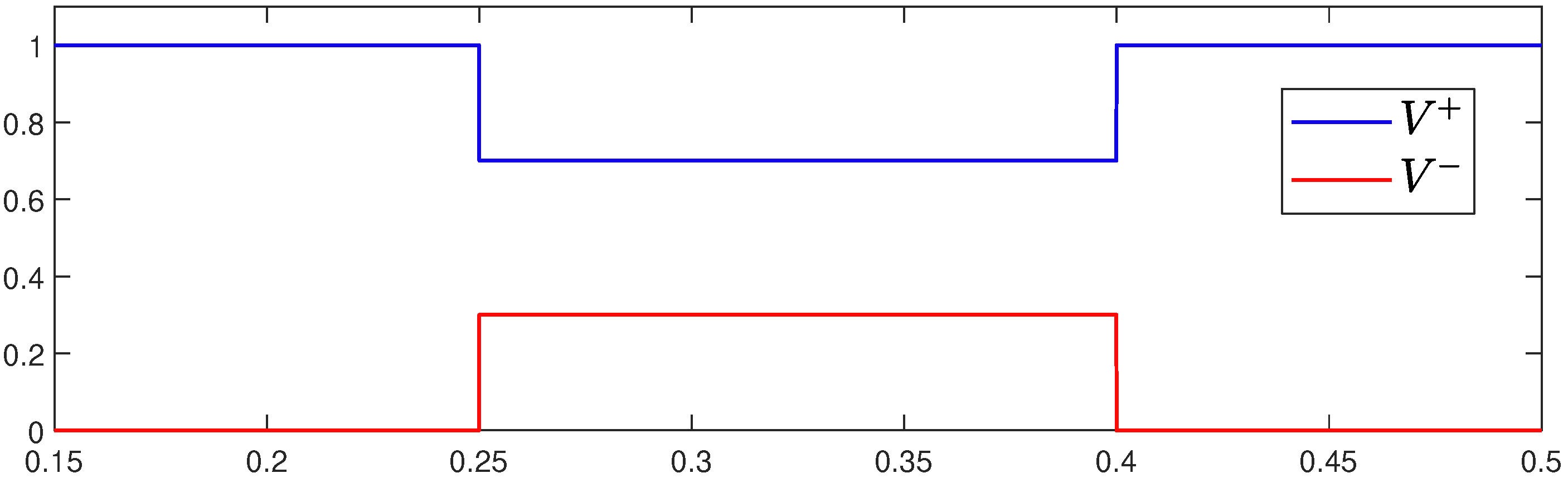
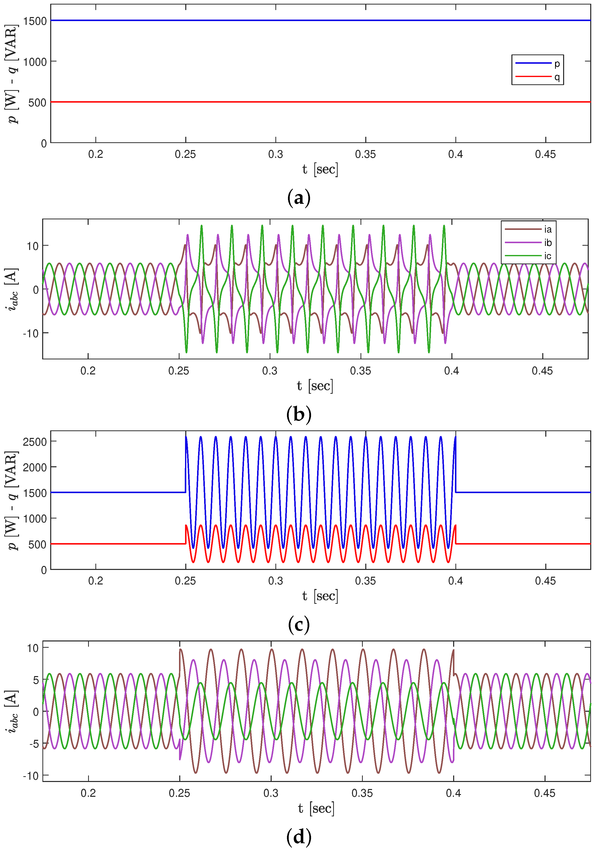
It can be observed that if k is selected as a constant term, then the powers have a constant and an oscillating component. Moreover, since a negative sign involves the consumption of power, k must be a positive value. To exemplify the impact of selecting different values of k, is selected to produce the injection of a sinusoidal oscillation in conjunction with a constant component equal to the reference power. This will be compared with the simulation results using k as the value presented in (8). A voltage sag scenario with the following characteristics was simulated: sag between (sec) with (V), (W), (VAR), (pu), (pu), (rad), and (rad) (see Figure 4).
Figure 5 shows the injected powers and currents values according to (7) if k is equal to (8) and , respectively. Notice that, as discussed, when k is equal to (8), distorted currents are injected during the voltage sag, with an injection of constant powers. On the contrary, the selection of avoids the distorted currents by allowing the injection of oscillations with zero-average value in the powers. This characteristic of flexible control can be exploited to define different operating points and reference generating blocks. Then, the power references can be set to guarantee restrictions imposed by the GCs or as a function of the power production in the DC stage.
5. Current State of Art
As mentioned above, several proposals of flexible current control have been presented in the specialized literature over the last years. Table 1 presents a summary of the most relevant contributions recently published. This table describes the application or absence of key characteristics for flexible current control, such as complying with the operational restrictions and achieving secondary objectives or other desired control features. In addition, the complexity of the control structures is categorized as low, medium, or high.
Table 1 begins with the IARC strategy, in which distorted currents are injected to guarantee constant power delivery. IARC uses the original current definition of the p-q power theory [62,64]. It is worth mentioning that the injection of high harmonic contents is not a common practice. Not only is the power quality affected, but also other technical issues must be considered. For instance, the injection of this kind of current is limited due to the low-pass effect of the grid-tied filter. As a matter of fact, the IARC is the only reviewed strategy that considers the injection of currents with high harmonic contents.
The review shows that most works only focus on ensuring a maximum current limit. Other operational restrictions, such as the maximum voltage limit, are not commonly addressed. Similarly, the capacity of regulating the balance between the power generated at the source and the power injected by the inverter to the system, which allows dealing with the extra energy during power curtailment action, has been barely explored [52,81]. Regarding the secondary objectives, the mitigation or cancellation of the oscillations is the most usual, while the active and reactive power oscillation control has been much less implemented.
One of the main aspects that the review brings out is that over the years, the proposals presented in the state-of-the-art have tended to include more features in order to improve the inverter performance. For instance, in the early works, the exclusive injection of P or Q during voltage sags was considered (not simultaneously), which can be sub-optimal [67,68,69,70]. In fact, multiple studies have concluded that if the grid impedance is considered for the simultaneous injection of P and Q, the voltage support can be enhanced [41,74,77,78].
On the other hand, simplicity is a favorable characteristic for the practical use of control strategies, since simple control schemes can be easily adapted to the operation with different GC. When more control features are considered, the strategies become more complex, and their computational burden increases. As shown in Figure 2, only the minimum value of the RCI is required in most GCs. Therefore, the strategies currently used in practice are those that focus on the injection of the maximum value of without considering optimal voltage support or other secondary objectives. This is one of the reasons why, in the near future, GCs must add new LVRT requirements.
Something remarkable is that the reactive current injection according to a grid code (RCI-GC) is taken into account in very few works [34,71]. Considering that each country defines its own RCI profile, some authors prefer to address the general problem. Nevertheless, studying the application of the strategies with specific GCs allows an in-depth analysis of the benefits and disadvantages of the proposals.
Improving the LVRT voltage support action considering simultaneously different operational restrictions, power scenarios, and types of voltage sags is a complex task with multiple solutions. The current trend of research in LVRT control strategies seeks to increase the number of features of the strategies to improve their operation. Considering the large number of operating scenarios that distribution grids can present, and the challenges of new GCs, the design of LVRT strategies is still a developing research subject. Section 7 discusses the current trends mentioned and the possibilities for future development in this area of research.
6. Design of an LVRT Flexible Current Algorithm
Based on the fundamentals previously presented, a generalizable methodology to conceive a flexible current algorithm applied to the LVRT capability is presented.
6.1. Scalar Factor Definition
The design of the control parameters of a flexible strategy is a cyclic process. The first step is the definition of the scalar factors to manipulate the current expression and achieve specific objectives. Even if these can be defined arbitrarily, it is convenient to apply criteria based on power theory in order to achieve the desired results [21]. On the other hand, assigning a physical meaning for these scalar factors is not mandatory. If the algorithm does not accomplish the expectations in the following steps, the designer must return to step one and start the process over.
The current definition shown in (10) and (11) is considered to perform an analysis and exemplify the steps of the design. This formulation has four scalar factors , , and that give flexibility to achieve multiple secondary objectives [34]. Garnica [82] has studied in detail the impact of these four parameters on the voltage support.
6.2. Injected Powers
The second step is to calculate the injected active and reactive powers according to the modified currents definition and analyze if these accomplish the desired control features. Equation (12) shows the delivered power by injecting (10) to the grid [78]; where .
The analysis of the effect of the factors on the injected powers is complex due to the non-linearity of Equation (12). Therefore, although these scalar factors can take any real value, it is recommended to define some discrete values that reduce the analysis to a limited number of case studies [50]. For example, assuming that each can take only one of these three values: −1, 0, or 1, there would be at least 81 control modes. As the analysis is focused on achieving some desired control features, not all of these modes must be considered. From (12), it is observed that the constant terms are equal to the reference powers and , and the values of control the oscillating components. Table 2 shows four specific cases of interest. Note that two of these allow cancelling the oscillating components of p or q but not both simultaneously. The other two cause the oscillations of p or q to depend only on the value of or .
6.3. Voltage Support Strategy
The third step is the evaluation of the voltage support action. It requires modeling the whole system to observe the control outcomes (see Figure 3). Since the inverter works in grid feeding or current mode, the PCC voltage restoration depends on the action of the currents. In addition, the support could be limited by the power production or power curtailment scenarios.
The voltage support is modeled by (13) in terms of the line impedance and the current injected to the grid (14).
Shabestary and Mohamed [48] have developed this model in the time domain to find the amplitudes of and . This paper uses the IEEE Std-241 approach, which leads to (15) and (16) [41,83]. It is assumed that the factors are equal to 1 to simplify the analysis. On the one hand, if the injected current angle is equal to the angle of , , and is maximized. On the other hand, is minimized since increases. Therefore, the voltage support is enhanced [41,78].
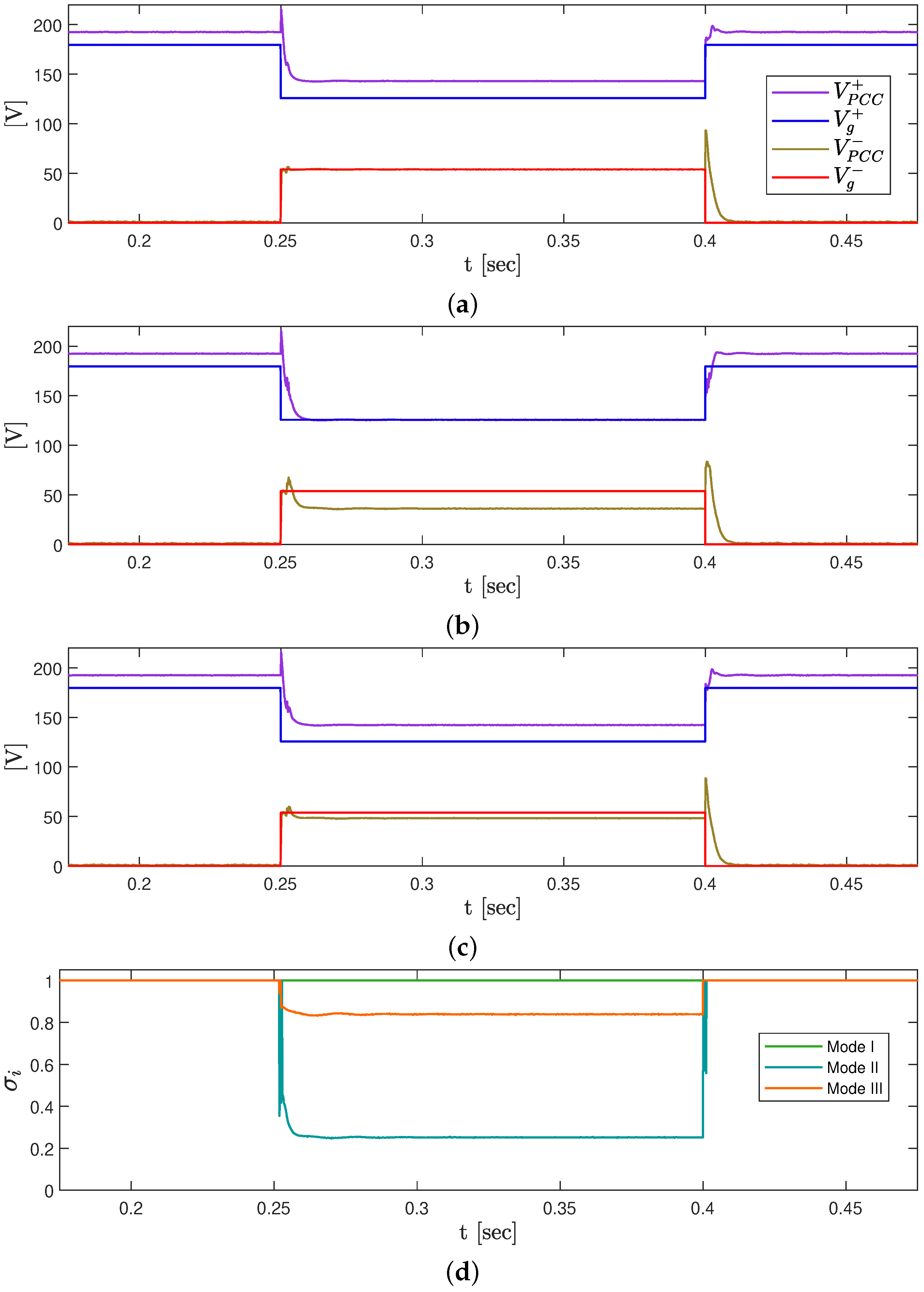
Figure 6 shows an example of how the values of the scalar factors impact the performance of the voltage support strategy. For this example, the parameters of the voltage sag described in Section 4.2 are used (see Figure 4).
The three operation strategies described in Section 2.3. were implemented, using the values presented in Table 3.
Mode II is a particular case because it requires setting a negative power reference enabling the power consumption through the negative sequence. As mentioned, the injected powers for the studied case will be the reference powers regardless of the values. Therefore, if is used instead of , active power will be injected through the negative sequence. As a consequence, the amplitude of will increase, which is undesired. The same concept also applies to reactive power. This kind of analysis shows why the power definition step is chosen before the voltage support verification. In Figure 6a,b, it is possible to observe the effect on the positive sequence and negative sequence voltage support, respectively. While in the first results, the value of is increased, in the second, is reduced as far as the limits of the system allow. Finally, in Figure 6c, a combination of these two effects is presented.
6.4. System Restrictions
Once it is verified that the control algorithm accomplishes the desired power injection and voltage support, the next step is to ensure that the control will satisfy the system restrictions.
6.4.1. Maximum Current Limitation
For the overcurrent control, the common strategy is to define each phase current in terms of the instantaneous values of the sequence voltages at the PCC and the reference powers. Hence, the performance of this method depends on the accuracy and speed of the synchronization algorithm to estimate the voltage components [84]. Equation (17) shows the maximum phase current calculated for the studied strategy (10), where , and . The maximum current is determined by the value of which maximizes the function described in (17).
If the values of the currents are out of range, a power curtailment strategy must be implemented. The strategy will be mainly defined by the GC requirements and the desired control features. Garnica et al. [34] have used Equation (17) to set the power curtailment according to the Spanish national GC. This paper presents an example of a power curtailment strategy focused on improving the voltage support by injecting a current at the angle of . To guarantee that the injected current angle coincides with angle, (18) must be satisfied. Then, the maximum phase current must be calculated according to (17), where (see (11)).
Two possible operating situations may emerge according to the power production scenario. If is greater than the nominal current of the inverter , the power curtailment factor must be applied. is calculated according to (19), and it is used to redefine the reference powers as and .
On the other hand, if is less than , the amplitude of the injected reactive current can be increased to employ the full inverter capacity. Therefore, a new reactive power reference must be calculated from (17) with and . Solving for the general case involves a complex procedure because should be treated as variables. Equation (20) shows for a simplified case in which , and .
In Figure 6d, it can be observed that the current limitation influences each voltage support strategy in a different way. Therefore, the performance of the voltage support strategy is linked to the power curtailment strategy and the power generation scenario.
6.4.2. Maximum Voltage Limitation
A similar approach as for the current limitation should be adopted for the voltage limitation. The phase voltages are decomposed in terms of the sequence components as shown in (21). Moreover, the maximum voltage value is determined by the value in , which maximizes the function described in (21) [48,81,85]. Regarding this, different formulations have being proposed. A widely used method is to use (13) to define the reference amplitudes and in terms of and , which are selected considering the GC’s requirements [68,69]. With these values, the power or current references to be injected are determined [48].
6.4.3. Maximum DC-Link Voltage
The value of is directly linked to the power balance between the generation source and the injected power to the grid [84,86]. Since the current limitation reduces the power injection capability of the inverter during a voltage sag, a key contribution of a control strategy from the AC side is to limit the amplitude of the active power oscillations to constrain the maximum value of [65,84,87]. However, this limitation and the management of the extra energy indicate that the power curtailment can be treated from the DC stage. Some common strategies consist of operating the system in a non-MPPT mode, the use of a breaking chopper resistor, or dumping the extra power in an EES such as batteries or supercapacitors [86,88,89]. This subject will be further discussed in Section 7.
6.5. Secondary Objectives
The last step involves reviewing the flexible current control capability to achieve other secondary objectives. The mitigation of powers oscillations and low harmonic contents are commonly treated objectives. As mentioned, active power oscillations can be treated by selecting properly the to minimize . Another option is to regulate the power production on the DC stage. In contrast, the reactive power oscillations can only be treated from the AC side. Regarding the harmonic content, most of the flexible current controllers use the approach presented in Section 4.2 to minimize harmonic contents. Nevertheless, some level of power oscillations or harmonic content may be acceptable if a suitable voltage recovery is achieved [79]. Once this analysis is complete, the designer must decide if the performance of the algorithm is adequate. Usually, some of the secondary objectives can only be accomplished under specific scenarios giving rise to different control modes [34]. Nevertheless, if the proposed control does not meet the desired behavior, the scalar factors must be redefined, and the designer must return to the first step.
6.6. Summary
The design steps of the exposed methodology are summarized in Figure 7. It is worth recalling that this methodology is presented to develop a flexible current control applied to LVRT capability. However, the fundamental concepts can be extended to other applications not covered by this work. The design could be an iterative cyclic process if the aimed objectives are not fulfilled.
7. Discussion
It is expected that the DPGS connected to electrical grids will increase in the coming years [22,25]. As a result, GCs will change accordingly, and more stringent requirements are expected, since renewable generation will significantly impact the grid stability [46,90]. One of the aspects that future GCs should consider is the definition of precise technical guides related to the voltage support operation, since some voltage support strategies perform better than others according to the fault type, the power generation scenario and the grid impedance.
Most GCs only contemplate reactive current injection [41]. However, according to the grid impedance and type of sag, strategies such as power consumption through negative sequence could be a better alternative than power injection via positive sequence during a power generation deficit. The drawback of the mentioned approach is that a resistor or an EES is required to enable power consumption.
The effect of the grid impedance is a key aspect that should be studied to improve the performance of the flexible current control strategies. Since the difference between the PCC voltage and the grid voltage is the voltage drop in the line, a small value of grid impedance implies that even with a high current injection, the voltage support impact will be minimal. Further analysis is required to define the inverter behavior under this particular condition. Although the principal characteristic of flexible current control is the application of the factors, the definition of methodologies based on design guidelines is still barely analyzed in the specialized literature. Although these scalar factors can take any real value, most of the studied works define them in a range of 0 to 1. This normalization is valid, since and are the reference variables. Therefore, a value above 1 could lead to a reference beyond the available or desired power. However, some flexible algorithms, such as Garnica [34], have the scalar in both the numerator and denominator, making this normalization unnecessary. The search for optimal factors is a complex task due to the non-linearity of the equations; hence, the study of these alternatives is an open research field.
The performance of the other control loops is another key factor. For the correct operation of the inverter during a voltage sag, these strategies must contemplate aspects that are not considered under normal operation conditions, i.e., the presence of negative sequence, ramp amplitudes and the effect of phase shifts on the grid voltages [27]. As an example, for the current limitation technique used in this paper, a fast and accurate estimation of the frequency and the sequence voltages, amplitudes and phases is critical. Therefore, the compatibility between the control loops must be verified.
In recent years, different works have focused on treating the active power balance and the DC-link voltage oscillations by regulating the power production in the DC stage [91]. The usual approach to maintain the power balance is to adjust . Nevertheless, this approach is limited, since a power curtailment scenario could be required during a fault condition. In such cases, the power balance must be treated from the DC side. There are three options to perform the power regulation. The first one is to regulate the generated power according to the control needs. The strategy to achieve this goal depends on the type of renewable source, making it the most complex of the presented options [92,93]. The second one is to consume the extra power using a chopper resistor [94]. Although it is a simple approach, it suffers from several drawbacks. In addition to the need for an additional resistor, a percentage of the available power is lost. Moreover, the resistor can only treat the excess of power but not its lack. The last option contemplates an energy storage element allowing bidirectional power flow. The main drawback of this approach is its high cost, since an additional power converter is necessary for the charge and discharge of the EES. Further analysis is required to select the best options. Such as analysis should contemplate that it is possible to combine the action of the inverter and the power source to manage the power balance simultaneously.
8. Conclusions
This paper presented an overview of flexible current control applied to the LVRT capability. The document aims to review the key aspects related to the foundation and operation of this type of control strategies. In addition, a generalizable methodology to design flexible current control algorithms was presented, giving general guidelines to the researchers interested in this research topic. Finally, a discussion was presented related to current and future trends.
Author Contributions
Conceptualization, D.J.R., M.A.M. and M.G.; methodology, D.J.R. and J.M.R.; software, D.J.R.; validation, M.A.M. and M.G.; formal analysis, D.J.R.; investigation, D.J.R.; resources, D.G.; writing—original draft preparation, D.J.R. and J.M.R.; writing—review and editing, M.A.M. and D.G.; visualization, J.M.R. and D.G.; supervision, M.A.M.; project administration, J.M.R.; funding acquisition, D.G. All authors have read and agreed to the published version of the manuscript.
Funding
This work was supported by Universidad Industrial de Santander and Minciencias, with project “Programa de Investigación en Tecnologías Emergentes para Microredes Eléctricas Inteligentes con Alta Penetración de Energias Renovables”, contract No. 80740-542-2020. In addition, this work comes within the scope of a research project ECOS Nord Colombia No. C21MP01 between Universidad Industrial de Santander and Université de Lorraine.
Institutional Review Board Statement
Not applicable.
Informed Consent Statement
Not applicable.
Data Availability Statement
The data presented in this study are available on request from the corresponding author.
Conflicts of Interest
The authors declare no conflict of interest.
References
- Blaabjerg, F.; Yang, Y.; Yang, D.; Wang, X. Distributed Power-Generation Systems and Protection. Proc. IEEE 2017, 105, 1311–1331. [Google Scholar] [CrossRef] [Green Version]
- Ufa, R.; Malkova, Y.; Rudnik, V.; Andreev, M.; Borisov, V. A review on distributed generation impacts on electric power system. Int. J. Hydrogen Energy 2022, 47, 20347–20361. [Google Scholar] [CrossRef]
- Chen, X.; Mcelroy, M.B.; Wu, Q.; Shu, Y.; Xue, Y. Transition towards higher penetration of renewables: An overview of interlinked technical, environmental and socio-economic challenges. J. Mod. Power Syst. Clean Energy 2019, 7, 1–8. [Google Scholar] [CrossRef] [Green Version]
- Kundur, P.; Paserba, J.; Vitet, S. Overview on definition and classification of power system stability. In Proceedings of the CIGRE/IEEE PES International Symposium Quality and Security of Electric Power Delivery Systems. CIGRE/PES 2003, Montreal, QC, Canada, 8–10 October 2003; pp. 1–4. [Google Scholar] [CrossRef]
- Peyghami, S.; Palensky, P.; Blaabjerg, F. An Overview on the Reliability of Modern Power Electronic Based Power Systems. IEEE Open J. Power Electron. 2020, 1, 34–50. [Google Scholar] [CrossRef] [Green Version]
- Tse, C.K.; Huang, M.; Zhang, X.; Liu, D.; Li, X.L. Circuits and Systems Issues in Power Electronics Penetrated Power Grid. IEEE Open J. Circuits Syst. 2020, 1, 140–156. [Google Scholar] [CrossRef]
- Zeb, K.; Islam, S.U.; Khan, I.; Uddin, W.; Ishfaq, M.; Curi Busarello, T.D.; Muyeen, S.; Ahmad, I.; Kim, H. Faults and Fault Ride Through strategies for grid-connected photovoltaic system: A comprehensive review. Renew. Sustain. Energy Rev. 2022, 158, 112125. [Google Scholar] [CrossRef]
- Zhang, Z.; Schuerhuber, R.; Fickert, L.; Friedl, K. Study of stability after low voltage ride-through caused by phase-locked loop of grid-side converter. Int. J. Electr. Power Energy Syst. 2021, 129, 106765. [Google Scholar] [CrossRef]
- Özgür, Ç.; Yalman, Y.; Tan, A.; Çağatay Bayındır, K.; Ümit, Ç.; Akdeniz, M.; Chaudhary, S.K.; Høyer, M.; Guerrero, J.M. Grid code requirements—A case study on the assessment for integration of offshore wind power plants in Turkey. Sustain. Energy Technol. Assessments 2022, 52, 102137. [Google Scholar]
- Heydari-doostabad, H.; Khalghani, M.R.; Khooban, M.H. A novel control system design to improve LVRT capability of fixed speed wind turbines using STATCOM in presence of voltage fault. Int. J. Electr. Power Energy Syst. 2016, 77, 280–286. [Google Scholar] [CrossRef]
- Howlader, A.M.; Senjyu, T. A comprehensive review of low voltage ride through capability strategies for the wind energy conversion systems. Renew. Sustain. Energy Rev. 2016, 56, 643–658. [Google Scholar] [CrossRef]
- Tang, C.Y.; Chen, Y.T.; Chen, Y.M. PV Power System With Multi-Mode Operation and Low-Voltage Ride-Through Capability. IEEE Trans. Ind. Electron. 2015, 62, 7524–7533. [Google Scholar] [CrossRef]
- Benali, A.; Khiat, M.; Allaoui, T.; Denaï, M. Power Quality Improvement and Low Voltage Ride Through Capability in Hybrid Wind-PV Farms Grid-Connected Using Dynamic Voltage Restorer. IEEE Access 2018, 6, 68634–68648. [Google Scholar] [CrossRef]
- Guo, X.; Liu, W.; Lu, Z. Flexible Power Regulation and Current-Limited Control of the Grid-Connected Inverter Under Unbalanced Grid Voltage Faults. IEEE Trans. Ind. Electron. 2017, 64, 7425–7432. [Google Scholar] [CrossRef]
- Al-Shetwi, A.Q.; Hannan, M.; Jern, K.P.; Mansur, M.; Mahlia, T. Grid-connected renewable energy sources: Review of the recent integration requirements and control methods. J. Clean. Prod. 2020, 253, 119831. [Google Scholar] [CrossRef]
- Al-Shetwi, A.Q.; Sujod, M.Z.; Blaabjerg, F.; Yang, Y. Fault ride-through control of grid-connected photovoltaic power plants: A review. Sol. Energy 2019, 180, 340–350. [Google Scholar] [CrossRef]
- Talha, M.; Amir, A.; Raihan, S.R.S.; Abd Rahim, N. Grid-connected photovoltaic inverters with low-voltage ride through for a residential-scale system: A review. Int. Trans. Electr. Energy Syst. 2021, 31, e12630. [Google Scholar] [CrossRef]
- Milicua, A.; Abad, G.; Rodríguez Vidal, M.A. Online Reference Limitation Method of Shunt-Connected Converters to the Grid to Avoid Exceeding Voltage and Current Limits Under Unbalanced Operatio—Part I: Theory. IEEE Trans. Energy Convers. 2015, 30, 852–863. [Google Scholar] [CrossRef]
- Sosa, J.L.; Castilla, M.; Miret, J.; Matas, J.; Al-Turki, Y.A. Control Strategy to Maximize the Power Capability of PV Three-Phase Inverters During Voltage Sags. IEEE Trans. Power Electron. 2016, 31, 3314–3323. [Google Scholar] [CrossRef] [Green Version]
- Rodriguez, P.; Timbus, A.V.; Teodorescu, R.; Liserre, M.; Blaabjerg, F. Flexible Active Power Control of Distributed Power Generation Systems During Grid Faults. IEEE Trans. Ind. Electron. 2007, 54, 2583–2592. [Google Scholar] [CrossRef]
- Camacho, A.; Castilla, M.; Miret, J.; Borrell, A.; de Vicuña, L.G. Active and Reactive Power Strategies With Peak Current Limitation for Distributed Generation Inverters During Unbalanced Grid Faults. IEEE Trans. Power Electron. 2015, 62, 1515–1525. [Google Scholar] [CrossRef]
- Afshari, E.; Moradi, G.R.; Rahimi, R.; Farhangi, B.; Yang, Y.; Blaabjerg, F.; Farhangi, S. Control Strategy for Three-Phase Grid-Connected PV Inverters Enabling Current Limitation Under Unbalanced Faults. IEEE Trans. Ind. Electron. 2017, 64, 8908–8918. [Google Scholar] [CrossRef] [Green Version]
- Camacho, A.; Castilla, M.; Miret, J.; Vasquez, J.C.; Alarcon-Gallo, E. Flexible Voltage Support Control for Three-Phase Distributed Generation Inverters Under Grid Fault. IEEE Trans. Ind. Electron. 2013, 60, 1429–1441. [Google Scholar] [CrossRef]
- Jia, J.; Yang, G.; Nielsen, A.H. A Review on Grid-Connected Converter Control for Short-Circuit Power Provision Under Grid Unbalanced Faults. IEEE Trans. Power Del. 2018, 33, 649–661. [Google Scholar] [CrossRef] [Green Version]
- Joshi, J.; Swami, A.K.; Jately, V.; Azzopardi, B. A Comprehensive Review of Control Strategies to Overcome Challenges During LVRT in PV Systems. IEEE Access 2021, 9, 121804–121834. [Google Scholar] [CrossRef]
- IEEE Std 1159-2019 (Revision of IEEE Std 1159-2009); IEEE Recommended Practice for Monitoring Electric Power Quality. IEEE: Piscataway, NJ, USA, 2019; pp. 1–98.
- Bollen, M.H. Understanding Power Quality Problems: Voltage Sags and Interruptions; John Wiley& Sons, Inc: Hoboken, NJ, USA, 2000; pp. 139–251. [Google Scholar]
- Garnica, M.; García de Vicuña, L.; Miret, J.; Camacho, A.; Guzmán, R. Voltage Support Experimental Analysis of a Low-Voltage Ride-Through Strategy Applied to Grid-Connected Distributed Inverters. Energies 2018, 11, 1949. [Google Scholar] [CrossRef] [Green Version]
- Swagata Das, S.S.; Ananthan, S.N. Fault Location on Transmission and Distribution Lines: Principles and Applications; John Wiley & Sons: Hoboken, NJ, USA, 2022; p. 2. [Google Scholar]
- Tleis, N. Power Systems Modelling and Fault Analysis; Academic Press: Cambridge, MA, USA, 2022; p. 12. [Google Scholar]
- Tarafdar Hagh, M.; Khalili, T. A review of fault ride through of PV and wind renewable energies in grid codes. Int. J. Energy Res. 2019, 43, 1342–1356. [Google Scholar] [CrossRef]
- Yadav, M.; Pal, N.; Saini, D.K. Low voltage ride through capability for resilient electrical distribution system integrated with renewable energy resources. Energy Rep. 2023, 9, 833–858. [Google Scholar] [CrossRef]
- Buraimoh, E.; Davidson, I.E. Overview of Fault Ride-Through Requirements for Photovoltaic Grid Integration, Design and Grid Code Compliance. In Proceedings of the 2020 9th International Conference on Renewable Energy Research and Application (ICRERA), Glasgow, UK, 27–30 September 2020; pp. 332–336. [Google Scholar]
- Garnica López, M.A.; García de Vicuña, J.L.; Miret, J.; Castilla, M.; Guzmán, R. Control Strategy for Grid-Connected Three-Phase Inverters During Voltage Sags to Meet Grid Codes and to Maximize Power Delivery Capability. IEEE Trans. Power Electron. 2018, 33, 9360–9374. [Google Scholar] [CrossRef] [Green Version]
- Zheng, Q.; Li, J.; Ai, X.; Wen, J.; Fang, J. Overview of grid codes for photovoltaic integration. In Proceedings of the 2017 IEEE Conference on Energy Internet and Energy System Integration (EI2), Beijing, China, 26–28 November 2017; pp. 1–6. [Google Scholar]
- P.O. 12.3. Requisitos de Respuesta Frente a Huecos de Tensión de las Instalaciones Eólica. Red Eléctrica de España (REE). 2006. Available online: https://www.ree.es/sites/default/files/01_ACTIVIDADES/Documentos/ProcedimientosOperacion/PO_resol_12.3_Respuesta_huecos_eolica.pdf (accessed on 11 January 2023).
- Italian Grid Code-Chapter 1 Section C—Access to the National Transmission Service; Terna Driving Energy: Roma, Italy, 2015.
- Sarkar, M.N.I.; Meegahapola, L.G.; Datta, M. Reactive Power Management in Renewable Rich Power Grids: A Review of Grid-Codes, Renewable Generators, Support Devices, Control Strategies and Optimization Algorithms. IEEE Access 2018, 6, 41458–41489. [Google Scholar] [CrossRef]
- Camacho, A.; Castilla, M.; Miret, J.; de Vicuña, L.G.; Miguel Andrés, G.L. Control Strategy for Distribution Generation Inverters to Maximize the Voltage Support in the Lowest Phase During Voltage Sags. IEEE Trans. Power Electron. 2018, 65, 2346–2355. [Google Scholar] [CrossRef]
- Celik, D.; Meral, M.E. Voltage Support Control Strategy of Grid-connected Inverter System Under Unbalanced Grid Faults to Meet Fault Ride Through Requirements. IET Gener. Transm. Distrib. 2020, 14, 3198–3210. [Google Scholar] [CrossRef]
- Camacho, A.; Castilla, M.; Miret, J.; de Vicuña, L.G.; Guzman, R. Positive and Negative Sequence Control Strategies to Maximize the Voltage Support in Resistive-Inductive Grids During Grid Faults. IEEE Trans. Power Electron. 2018, 33, 5362–5373. [Google Scholar] [CrossRef] [Green Version]
- Duong, M.Q.; Leva, S.; Mussetta, M.; Le, K.H. A Comparative Study on Controllers for Improving Transient Stability of DFIG Wind Turbines During Large Disturbances. Energies 2018, 11, 480. [Google Scholar] [CrossRef] [Green Version]
- Resolucion No 60 del 2019: Modificaciones al Reglamento de Operación para permitir la conexión y operación de plantas solares fotovoltaicas y eólicas en el SIN. Comisión de Regulación de Energía y Gas CREG. 2019. Available online: http://apolo.creg.gov.co/Publicac.nsf/1c09d18d2d5ffb5b05256eee00709c02/ca640edbe4b7b5100525842d0053745d/$FILE/Creg060-2019.pdf (accessed on 27 December 2022).
- Technical Regulation 3.2.2 for PV Power Plants above 11 kW; Energinet: Fredericia, Denmark, 2016.
- The Grid Code; Electricity System Operator for Great Britain; National Grid ESO: Warwick, UK, 2020.
- Ge, J.; Shuai, Z.; Tu, C.; Luo, A.; Shen, Z.J. Flexible Control Strategy for Enhancing Power Injection Capability of Three-Phase Four-Wire Inverter During Asymmetrical Grid Faults. IEEE Trans. Power Electron. 2021, 36, 9592–9608. [Google Scholar] [CrossRef]
- Miret, J.; Garnica López, M.; Vicuña, L.; Camacho, A. PI-based controller for low-power distributed inverters to maximize reactive current injection while avoiding over voltage during voltage sags. IET Power Electron. 2018, 12, 83–91. [Google Scholar] [CrossRef]
- Shabestary, M.M.; Mohamed, Y.A.I. Advanced Voltage Support and Active Power Flow Control in Grid-Connected Converters Under Unbalanced Conditions. IEEE Trans. Power Electron. 2018, 33, 1855–1864. [Google Scholar] [CrossRef]
- Tafti, H.D.; Maswood, A.I.; Konstantinou, G.; Pou, J.; Townsend, C.D. Low-voltage ride-through capability of full-row connected cascaded H-bridge converters. In Proceedings of the 2016 IEEE Region 10 Conference (TENCON), Singapore, 22–25 November 2016; pp. 984–987. [Google Scholar]
- Afshari, E.; Moradi, G.R.; Yang, Y.; Farhangi, B.; Farhangi, S. A review on current reference calculation of three-phase grid-connected PV converters under grid faults. In Proceedings of the 2017 IEEE Power and Energy Conference at Illinois (PECI), Champaign, IL, USA, 23–24 February 2017; pp. 1–7. [Google Scholar]
- Xu, C.; Xuehua, W.; Xinbo, R.; Cheng, W.; Huanyu, W. A Low-Voltage Ride-Through Control Strategy for Two-Stage T-Type Three-Level Photovoltaic Inverters Limiting DC-Link Overvoltage and Grid-Side Overcurrent. In Proceedings of the 2018 20th European Conference on Power Electronics and Applications (EPE’18 ECCE Europe), Riga, Latvia, 17–21 September 2018; pp. P.1–P.10. [Google Scholar]
- Naresh, P.; Sravan Kumar, V.S. Analysis of Low Voltage Ride Through Techniques for Grid-Connected Photovoltaic Systems. In Proceedings of the 2020 IEEE International Conference on Power Electronics, Smart Grid and Renewable Energy (PESGRE2020), Cochin, India, 2–4 January 2020; pp. 1–7. [Google Scholar]
- Mahela, O.P.; Shaik, A.G. Comprehensive overview of grid interfaced solar photovoltaic systems. Renew. Sustain. Energy Rev. 2017, 68, 316–332. [Google Scholar] [CrossRef]
- Solatialkaran, D.; Khajeh, K.G.; Zare, F. A Novel Filter Design Method for Grid-Tied Inverters. IEEE Trans. Power Electron. 2021, 36, 5473–5485. [Google Scholar] [CrossRef]
- Yagnik, U.P.; Solanki, M.D. Comparison of L, LC & LCL filter for grid connected converter. In Proceedings of the 2017 International Conference on Trends in Electronics and Informatics (ICEI), Tirunelveli, India, 11–12 May 2017; pp. 455–458. [Google Scholar]
- Mohammad Reza, M.M. Performance Comparison of Synchronous Reference Frame-Based PLLs Topologies Under Power Quality Disturbances. Iran. J. Sci. Technol. Trans. Electr. Eng. 2018, 43, 307–321. [Google Scholar]
- Pei, D.; Xia, Y. Robust Power System Frequency Estimation Based on a Sliding Window Approach Mathematical Problems in Engineering. Hindawi 2019, 2019, 1–98. [Google Scholar]
- Sun, M.; Sahinoglu, Z. Extended Kalman filter based grid synchronization in the presence of voltage unbalance for smart grid. In Proceedings of the ISGT 2011, Anaheim, CA, USA, 17–19 January 2011; pp. 1–4. [Google Scholar] [CrossRef]
- Milano, F. A Geometrical Interpretation of Frequency. IEEE Trans. Power Syst. 2022, 37, 816–819. [Google Scholar] [CrossRef]
- Pal, B.; Sahu, P.K.; Mohapatra, S. A review on feedback current control techniques of grid-connected PV inverter system with LCL filter. In Proceedings of the 2018 Technologies for Smart-City Energy Security and Power (ICSESP), Bhubaneswar, India, 28–30 March 2018; pp. 1–6. [Google Scholar]
- Guo, W.-Q.; Wu, W.-Y. Improved current regulation of three-phase grid-connected voltage-source inverters for distributed generation systems. IET Renew. Power Gener. 2010, 4, 101–115. [Google Scholar] [CrossRef]
- Akagi, H.; Watanabe, E.H.; Aredes, M. Instantaneous Power Theory and Applications to Power Conditioning; Wiley-IEEE Press: Piscataway, NJ, USA, 2017. [Google Scholar]
- ORourke, C.J.; Qasim, M.M.; Overlin, M.R.; Kirtley, J.L. A Geometric Interpretation of Reference Frames and Transformations: dq0, Clarke, and Park. IEEE Trans. Energy Convers. 2019, 34, 2070–2083. [Google Scholar] [CrossRef] [Green Version]
- Teodorescu, R.; Liserre, M.; Rodriguez, P. Grid Converters for Photovoltaic and Wind Power Systems; Wiley-IEEE Press: Piscataway, NJ, USA, 2011. [Google Scholar]
- Meral, M.E.; Celik, D. Mitigation of DC-link voltage oscillations to reduce size of DC-side capacitor and improve lifetime of power converter. Electr. Power Syst. Res. 2021, 194, 107048. [Google Scholar] [CrossRef]
- Teodorescu, R.; Liserre, M.; Rodriguez, P. Grid Converters for Photovoltaic and Wind Power Systems; John Wiley & Sons: Chichester, WS, UK, 2007; Chapter 10; pp. 237–287. [Google Scholar]
- Miret, J.; Castilla, M.; Camacho, A.; Vicuña, L.G.d.; Matas, J. Control Scheme for Photovoltaic Three-Phase Inverters to Minimize Peak Currents During Unbalanced Grid-Voltage Sags. IEEE Trans. Power Electron. 2012, 27, 4262–4271. [Google Scholar] [CrossRef]
- Miret, J.; Camacho, A.; Castilla, M.; de Vicuña, L.G.; Matas, J. Control Scheme With Voltage Support Capability for Distributed Generation Inverters Under Voltage Sags. IEEE Trans. Power Electron. 2013, 28, 5252–5262. [Google Scholar] [CrossRef]
- Castilla, M.; Miret, J.; Camacho, A.; Matas, J.; García de Vicuña, L. Voltage Support Control Strategies for Static Synchronous Compensators Under Unbalanced Voltage Sags. IEEE Trans. Power Electron. 2014, 61, 808–820. [Google Scholar] [CrossRef]
- Guo, X.; Zhang, X.; Wang, B.; Wu, W.; Guerrero, J.M. Asymmetrical Grid Fault Ride-Through Strategy of Three-Phase Grid-Connected Inverter Considering Network Impedance Impact in Low-Voltage Grid. IEEE Trans. Power Electron. 2014, 29, 1064–1068. [Google Scholar] [CrossRef] [Green Version]
- Camacho, A.; Castilla, M.; Miret, J.; Guzman, R.; Borrell, A. Reactive Power Control for Distributed Generation Power Plants to Comply With Voltage Limits During Grid Faults. IEEE Trans. Power Electron. 2014, 29, 6224–6234. [Google Scholar] [CrossRef] [Green Version]
- Mirhosseini, M.; Pou, J.; Agelidis, V.G. Individual Phase Current Control With the Capability to Avoid Overvoltage in Grid-Connected Photovoltaic Power Plants Under Unbalanced Voltage Sags. IEEE Trans. Power Electron. 2015, 30, 5346–5351. [Google Scholar] [CrossRef]
- Wang, Y.; Ping, Y.; Zhirong, X. Flexible Voltage Support Control with Imbalance Mitigation Capability for Inverter-Based Distributed Generation Power Plants under Grid Faults. J. Power Electron. 2016, 16, 1551–1564. [Google Scholar] [CrossRef]
- Jin, P.; Li, Y.; Li, G.; Chen, Z.; Zhai, X. Optimized hierarchical power oscillations control for distributed generation under unbalanced conditions. Appl. Energy 2017, 194, 343–352. [Google Scholar] [CrossRef] [Green Version]
- Huka, G.B.; Li, W.; Chao, P.; Peng, S. A comprehensive LVRT strategy of two-stage photovoltaic systems under balanced and unbalanced faults. Int. J. Electr. Power Energy Syst. 2018, 103, 288–301. [Google Scholar] [CrossRef]
- Celik, D.; Meral, M.E. A flexible control strategy with overcurrent limitation in distributed generation systems. Int. J. Electr. Power Energy Syst. 2019, 104, 456–471. [Google Scholar] [CrossRef]
- Shuvra, M.A.; Chowdhury, B. Distributed dynamic grid support using smart PV inverters during unbalanced grid faults. IET Renew. Power Gener. 2019, 13, 598–608. [Google Scholar] [CrossRef]
- Garnica, M.; de Vicuña, L.G.; Miret, J.; Castilla, M.; Guzmán, R. Optimal Voltage-Support Control for Distributed Generation Inverters in RL Grid-Faulty Networks. IEEE Trans. Power Electron. 2020, 67, 8405–8415. [Google Scholar] [CrossRef] [Green Version]
- Meral, M.E.; Çelik, D. Minimisation of power oscillations with a novel optimal control strategy for distributed generation inverter under grid faulty and harmonic networks. IET Renew. Power Gener. 2020, 14, 3010–3022. [Google Scholar] [CrossRef]
- Castilla, M.; Camacho, A.; Miret, J.; Guzmán, R.; de Vicuña, L.G. Avoiding overvoltage problems in three-phase distributed-generation systems during unbalanced voltage sags. IET Power Electron. 2020, 13, 1537–1545. [Google Scholar] [CrossRef] [Green Version]
- Ding, G.; Gao, F.; Tian, H.; Ma, C.; Chen, M.; He, G.; Liu, Y. Adaptive DC-Link Voltage Control of Two-Stage Photovoltaic Inverter During Low Voltage Ride-Through Operation. IEEE Trans. Power Electron. 2016, 31, 4182–4194. [Google Scholar] [CrossRef]
- Garnica, M. Control of Grid-Connected Three-Phase Three-Wire Voltage-Sourced Inverters under Voltage Disturbances. Ph.D. Thesis, Universitat Politécnica de Catalunya, Catalonia, Spain, 2018. [Google Scholar]
- IEEE Std 241-1990; IEEE Recommended Practice for Electric Power Systems in Commercial Buildings. IEEE: Piscataway, NJ, USA, 1991; pp. 1–768.
- Just, H.; Gentejohann, M.; Eggers, M.; Dieckerhoff, S. Analysis and Control of DC-link Oscillations of Voltage Source Inverters during Unbalanced Grid Faults. In Proceedings of the 2019 21st European Conference on Power Electronics and Applications (EPE ’19 ECCE Europe), Genova, Italy, 3–5 September 2019; pp. P.1–P.10. [Google Scholar]
- Sufyan, M.; Rahim, N.A.; Eid, B.; Raihan, S.R.S. A comprehensive review of reactive power control strategies for three phase grid connected photovoltaic systems with low voltage ride through capability. J. Renew. Sustain. Energy 2019, 11, 042701. [Google Scholar] [CrossRef]
- Mohammedsaeed, E.K.; Jia, K. Comparison of some low voltage ride-through strategies. In Proceedings of the IECON 2017—43rd Annual Conference of the IEEE Industrial Electronics Society, Beijing, China, 29 October–1 November 2017; pp. 152–157. [Google Scholar]
- Bak, Y.; Lee, J.S.; Lee, K.B. Low-Voltage Ride-Through Control Strategy for a Grid-Connected Energy Storage System. Appl. Sci. 2018, 8, 57. [Google Scholar] [CrossRef]
- Talha, M.; Raihan, S.; Rahim, N.A. PV inverter with decoupled active and reactive power control to mitigate grid faults. Renew. Energy 2020, 162, 877–892. [Google Scholar] [CrossRef]
- Talha, M.; Raihan, S.R.S.; Rahim, N.A.; Akhtar, M.N.; Butt, O.M.; Hussain, M.M. Multi-Functional PV Inverter With Low Voltage Ride-Through and Constant Power Output. IEEE Access 2022, 10, 29567–29588. [Google Scholar] [CrossRef]
- Yang, Y.; Enjeti, P.; Blaabjerg, F.; Wang, H. Wide-Scale Adoption of Photovoltaic Energy: Grid Code Modifications Are Explored in the Distribution Grid. IEEE Ind. Appl. Mag. 2015, 21, 21–31. [Google Scholar] [CrossRef] [Green Version]
- Rincon, D.J.; Mantilla, M.A.; Rey, J.M.; Garnica, M. DC Stage Modelling for LVRT Capability in Photovoltaic Systems. In Proceedings of the IECON 2021—47th Annual Conference of the IEEE Industrial Electronics Society, Toronto, ON, Canada, 13–16 October 2021; pp. 1–7. [Google Scholar]
- Ezzat, M.; Benbouzid, M.; Muyeen, S.; Harnefors, L. Low-voltage ride-through techniques for DFIG-based wind turbines: State-of-the-art review and future trends. In Proceedings of the IECON 2013—39th Annual Conference of the IEEE Industrial Electronics Society, Vienna, Austria, 10–13 November 2013; pp. 7681–7686. [Google Scholar] [CrossRef] [Green Version]
- Islam, H.; Mekhilef, S.; Shah, N.B.M.; Soon, T.K.; Seyedmahmousian, M.; Horan, B.; Stojcevski, A. Performance Evaluation of Maximum Power Point Tracking Approaches and Photovoltaic Systems. Energies 2018, 11, 365. [Google Scholar] [CrossRef] [Green Version]
- Mendes, V.F.; Matos, F.F.; Liu, S.Y.; Cupertino, A.F.; Pereira, H.A.; De Sousa, C.V. Low Voltage Ride-through Capability Solutions for Permanent Magnet Synchronous Wind Generators. Energies 2016, 9, 59. [Google Scholar] [CrossRef]


Figure 3.
Scheme of a grid-connected inverter.

Figure 4.
Sequence components amplitudes of the studied voltage sag.

Figure 5.
(a) p and q with k equal to (8); (b) injected currents with k equal to (8); (c) p and q with ; (d) injected currents with .

Figure 6.
Voltage Support Simulations (a) Mode I: maximization of the positive sequence voltage; (b) Mode II: minimization of the negative sequence voltage; (c) Mode III: combination of Mode I and Mode II; and (d) for each voltage support model.
Figure 6.
Voltage Support Simulations (a) Mode I: maximization of the positive sequence voltage; (b) Mode II: minimization of the negative sequence voltage; (c) Mode III: combination of Mode I and Mode II; and (d) for each voltage support model.

Figure 7.
Flexible current control design steps.


Table 1.
Characteristics of different reference current generators.
| Control Strategy | Year | Flexible | Restrictions | Secondary Objectives | Control Features | |||||||||
|---|---|---|---|---|---|---|---|---|---|---|---|---|---|---|
| Over Current Control | Over Voltage Control | Deals with Power Curtailment | Osc. Control | Osc. Control | Injection | Grid Impedance | RCI-GC | Complexity | ||||||
| P | Q | |||||||||||||
| [64] | * | × | ✓ | × | × | ✓ | ✓ | ✓ | ✓ | ✓ | × | × | × | Low |
| [67] | 2012 | ✓ | × | × | × | ✓ | × | ✓ | ✓ | × | × | ✓ | × | Low |
| [68] | 2013 | ✓ | ∘ | ✓ | × | × | × | × | × | ✓ | × | ✓ | × | Low |
| [23] | 2013 | ✓ | ✓ | × | × | ∘ | × | × | ✓ | ✓ | × | ✓ | × | Medium |
| [69] | 2014 | ✓ | ✓ | ✓ | × | × | × | × | × | ✓ | × | ✓ | ✓ | Medium |
| [70] | 2014 | ✓ | × | × | × | × | × | × | ✓ | × | ✓ | × | × | Low |
| [71] | 2014 | × | ✓ | ✓ | × | × | × | - | × | ✓ | × | ✓ | ✓ | Low |
| [21] | 2015 | ✓ | ✓ | × | ✓ | × | × | × | ✓ | ✓ | ✓ | ✓ | × | Low |
| [18] | 2015 | × | ✓ | ✓ | × | × | × | ✓ | × | ✓ | × | ✓ | × | Medium |
| [72] | 2015 | × | ✓ | ✓ | × | × | × | × | ✓ | ✓ | × | ✓ | × | Low |
| [73] | 2016 | × | ✓ | × | ✓ | ∘ | × | × | ✓ | ✓ | × | × | ✓ | Low |
| [74] | 2016 | × | × | × | × | ∘ | ∘ | ∘ | ✓ | ✓ | ✓ | ✓ | × | Low |
| [19] | 2016 | ✓ | ✓ | × | × | ✓ | × | ✓ | ✓ | ✓ | × | × | × | Low |
| [22] | 2017 | ✓ | ✓ | × | ✓ | ✓ | × | ✓ | ✓ | ✓ | × | × | × | Medium |
| [75] | 2018 | ✓ | ✓ | ✓ | × | × | × | × | × | ✓ | × | ✓ | × | Low |
| [34] | 2018 | ✓ | ✓ | × | × | ∘ | × | ∘ | ✓ | ✓ | × | × | ✓ | Medium |
| [48] | 2018 | × | ✓ | ✓ | ✓ | ∘ | × | ∘ | ✓ | ✓ | ✓ | ✓ | × | High |
| [41] | 2018 | × | ✓ | × | × | × | × | × | ✓ | ✓ | ✓ | ✓ | × | Low |
| [47] | 2018 | ✓ | ✓ | ✓ | × | × | × | - | ✓ | ✓ | × | ✓ | ✓ | Low |
| [76] | 2019 | ✓ | ✓ | × | × | ∘ | ∘ | ∘ | ✓ | ✓ | × | × | × | Medium |
| [77] | 2019 | × | ✓ | × | × | × | × | × | ✓ | ✓ | ✓ | ✓ | × | Low |
| [40] | 2020 | ✓ | ✓ | ✓ | × | ∘ | ∘ | ∘ | ✓ | ✓ | ✓ | ✓ | × | Medium |
| [78] | 2020 | ✓ | ✓ | × | × | ✓ | × | ✓ | ✓ | ✓ | ✓ | ✓ | × | Low |
| [79] | 2020 | ✓ | ✓ | × | × | ∘ | ∘ | ∘ | ✓ | ✓ | × | × | × | Medium |
| [80] | 2020 | ✓ | ✓ | ✓ | × | ∘ | ∘ | × | ✓ | ✓ | × | ✓ | ✓ | Medium |
| [65] | 2021 | ∘ | ✓ | × | × | ✓ | ∘ | ✓ | ✓ | ✓ | × | × | × | Low |
✓ Achieved or partially covered × Not achieved ∘ Achieved under certain conditions — Unable to determine. 1 Over current control refers to the limitation of the maximum instantaneous phase current. 2 Over-voltage control refers to the limitation of the maximum instantaneous phase voltage at the PCC. 3 Power curtailment refers to the capability of the control to deal with the extra energy on the DC stage caused by the power curtailment. 4 Oscillation control describes if power oscillations are canceled or mitigated. 5 The table shows if the algorithm is able to inject active and/or reactive power during the voltage sag. 6 Grid impedance shows if the resistance or the inductance are considered in the control strategy. 7 RCI-GC refers to reactive current injection according to the grid code. * Although it was named as IARC by Rodriguez in 2007 [20], this strategy correspond to the power definition according to the Instantaneous Power Theory.
Table 2.
Power behavior for different combinations.
| Mode | ||||||||||
|---|---|---|---|---|---|---|---|---|---|---|
| 1 | 1 | 1 | 1 | 1 | ✓ | 0 | 0 | ✓ | ||
| 2 | 1 | −1 | 1 | −1 | 0 | ✓ | ✓ | 0 | ||
| 3 | 1 | −1 | 1 | 1 | 0 | 0 | ✓ | ✓ | ||
| 4 | 1 | 1 | 1 | −1 | ✓ | ✓ | 0 | 0 | ||
✓ Oscillations are caused by this component.
Table 3.
combinations for the voltage support analysis.
| Mode | Voltage Support | ||||
|---|---|---|---|---|---|
| I | ↑ | 1 | 0 | 1 | 0 |
| II | ↓ | 0 | 1 | 0 | 1 |
| III | ↑ and ↓ | 1 | −1 | 1 | 1 |
↑ Increase, ↓ decrease.
Disclaimer/Publisher’s Note: The statements, opinions and data contained in all publications are solely those of the individual author(s) and contributor(s) and not of MDPI and/or the editor(s). MDPI and/or the editor(s) disclaim responsibility for any injury to people or property resulting from any ideas, methods, instructions or products referred to in the content. |
© 2023 by the authors. Licensee MDPI, Basel, Switzerland. This article is an open access article distributed under the terms and conditions of the Creative Commons Attribution (CC BY) license (https://creativecommons.org/licenses/by/4.0/).
Share and Cite
MDPI and ACS Style
Rincon, D.J.; Mantilla, M.A.; Rey, J.M.; Garnica, M.; Guilbert, D. An Overview of Flexible Current Control Strategies Applied to LVRT Capability for Grid-Connected Inverters. Energies 2023, 16, 1052. https://doi.org/10.3390/en16031052
AMA Style
Rincon DJ, Mantilla MA, Rey JM, Garnica M, Guilbert D. An Overview of Flexible Current Control Strategies Applied to LVRT Capability for Grid-Connected Inverters. Energies. 2023; 16(3):1052. https://doi.org/10.3390/en16031052
Chicago/Turabian StyleRincon, David J., Maria A. Mantilla, Juan M. Rey, Miguel Garnica, and Damien Guilbert. 2023. "An Overview of Flexible Current Control Strategies Applied to LVRT Capability for Grid-Connected Inverters" Energies 16, no. 3: 1052. https://doi.org/10.3390/en16031052
Note that from the first issue of 2016, this journal uses article numbers instead of page numbers. See further details here.