
Charge Estimation of Piezoelectric Actuators: A Comparative Study


1
Engineering Department, Birmingham City University, Birmingham B4 7XG, UK
2
Ministry of Housing and Urban Planning, Muscat 512, Oman
3
School of Energy and Electronic Engineering, University of Portsmouth, Portsmouth PO1 3DJ, UK
*
Author to whom correspondence should be addressed.
Energies 2023, 16(10), 3982; https://doi.org/10.3390/en16103982
Submission received: 24 March 2023
/
Revised: 1 May 2023
/
Accepted: 7 May 2023
/
Published: 9 May 2023
(This article belongs to the Special Issue Recent Advances and Future Challenges in Energy Applications and Control of Piezoelectric Actuators)
Abstract
:This article first reviews the position control of piezoelectric actuators, particularly charge-based sensorless control systems, which often include a charge estimator as a key component. The rest of the paper is about charge estimators for piezoelectric actuators. Two of the most recent/effective types of these estimators utilise either a sensing capacitor (type I in this paper) or a sensing resistor (type II); the latter (and the newer) type is broadly known as a digital charge estimator. Some experimental results in the literature show that, with the same loss in excitation voltage, a considerably higher amount of charge can be estimated with a type II estimator in comparison with a type I estimator; therefore, the superiority of type II estimators was acknowledged. In order to re-assess this conclusion, this paper equitably compares type I and II estimators through analytical modelling and experimentation. The results indicate that type II estimators have only a slight advantage in estimating higher amounts of charge, if both type I and II estimators are designed appropriately. At the same time, type II estimators have disadvantages; e.g., the resistance of type II estimators has to be tuned to suit different excitation frequencies. This research concludes that capacitor-based (type I) charge estimators for piezoelectric actuators, with pertinent design and implementation, can be still the prime solution for many charge estimation problems despite claims in the literature in the last decade.
1. Introduction
In piezoelectric materials, discovered by the Currie brothers in the 19th century, mechanical and electrical quantities are interconvertible due to asymmetrical distribution of the electrons in ions [1]. As a result of this asymmetry, mechanical force, through moving ions, provides energy to electrons, and this results in electrical voltage. This property is used in sensors [2,3,4]. Furthermore, electrical voltage, through pushing electrons, moves ions and generates deformation. This latter phenomenon is known as inverse piezoelectricity [5]. Devices made of piezoelectric materials and purposely fabricated to utilise inverse piezoelectricity are known as piezoelectric actuators [6]. Piezoelectric actuators have been used in the fabrication of motors [7] and for energy harvesting [8], fuel injection [9], inkjet printing [10], vibration control [11], and precise positioning [12] including micro/ nanopositioning [13].
Micro/nanopositioning aims at precise position control at the micro/nanometre scale. Piezoelectric actuators are the most precise, least bulky and most common actuators for micro/nanopositioning, and are anticipated to uphold their prime status for years [14,15]. Fine machining [16], manipulation of biological cells [17], scanning probe microscopy [18], and precise robotic surgery [19] are some applications of micro/nanopositioning with piezoelectric actuators or piezo-actuated micro/nanopositioning.
The key task in piezo-actuated micro/nanopositioning is precise control of the actuator’s position. The position of (an unfixed point/surface of) a piezoelectric actuator is its displacement from the relaxed state when the actuator has not been subject to any electrical or mechanical excitation for a considerably long period (e.g., some minutes) [20]. Experiments have demonstrated that the position of a piezoelectric actuator is proportional to its electric charge for an extensive operating area [21,22,23]. Therefore, a charge estimator can replace a costly and troublesome accurate position/displacement sensor; this motivates research on charge estimation for piezoelectric actuators [24,25].
This paper first briefly introduces different approaches to the position control of piezoelectric actuators, particularly sensorless control. Then, Section 3 critically reviews the most recent/advanced types of charge estimators for piezoelectric actuators. The most recently devised charge estimators have either a sensing capacitor or a sensing resistor. The ones with a sensing resistor are often called digital charge estimators; they have been claimed to be superior in the literature [22,26]. This paper questions this superiority. Section 5, Section 6 and Section 7 report an even-handed comparison of a charge estimator with a sensing resistor and one with a sensing capacitor based on analytical formulation and experiments.
2. Background-Fundamentals of Position Control of Piezoelectric Actuators
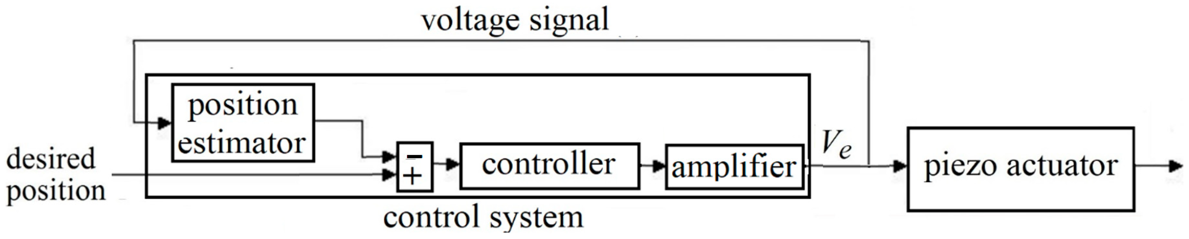
Figure 1a depicts a conventional feedback position control system for a piezoelectric actuator, including a position sensor and a voltage amplifier. Ve stands for the excitation voltage, the input voltage to the piezoelectric actuator. A precise position sensor (e.g., among the ones listed in [15]) imposes considerable cost and more importantly serious limits in terms of space and calibration on the micro/nanopositioning system. Consequently, sensorless approaches have attracted a lot of attention [22,27,28]. The simplest control architecture for sensorless control is feedforward, as depicted in Figure 1b (similar to [29]); however, this architecture sacrifices accuracy, having no signal representing the actuator’s position.
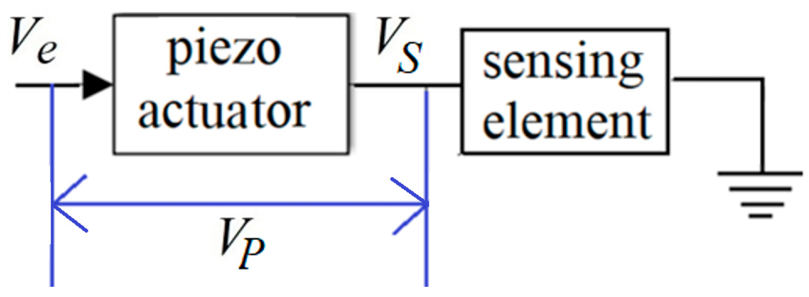
Another approach to sensorless control is the use of (an) easy-to-measure electrical signal(s) to represent or estimate position. Two most prevalent signals for this purpose are the voltage across the piezoelectric actuator, known as piezoelectric voltage, VP, and the voltage across a sensing element, known as sensor voltage, VS. Figure 2 depicts a common arrangement to find VP and VS; evidently, if there is no sensing element in Figure 2, VP = Ve.
VP has mostly been used as the input to a model to estimate position, e.g., in Figure 3. Sensorless control systems using VP are known as voltage-based sensorless systems. They are based on models mapping VP to position. A very wide range of research has been carried out to develop such models, due to inherited nonlinearity and the complexity of the VP and position relationship [30,31,32,33,34,35]. Inverted versions of these models have been developed to receive the desired positions and estimate their corresponding VP, which is equal to Ve in the absence of sensing elements. Such inverted models can be the controller in Figure 1b [33,36].
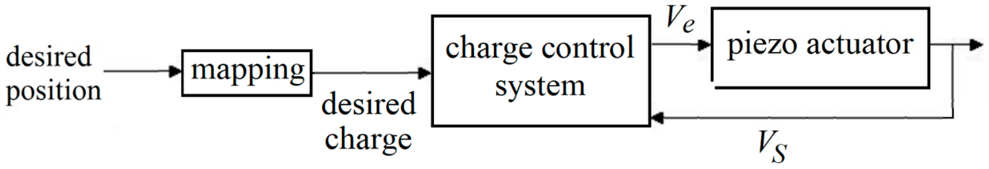
On the other hand, VS is often used to estimate charge rather than position. Advantageously, charge and position are proportionally related in wide operating areas for many piezoelectric actuators [37]; thus, finding charge from position or vice versa is often not a difficult task. Hence, sensorless control systems using VS are known as charge-based sensorless systems [37,38]. Figure 4 shows a general schematic of such a control system.
A charge control system of piezoelectric actuators, also known as a “charge drive(r)” [6,37] or “charge amplifier” [39,40], generally consists of a charge estimator and a feedback control system. In some charge drivers, e.g., the ones with two switching current or voltage sources [41,42], the charge estimators do not function independently and only operate when the whole charge drive operates. Such charge estimators are largely obsolete and outside the scope of this paper. Most of the reported charge control systems have a separable charge estimator. This separability facilitates individual development of each subset of the control system and improves its adaptability to new applications. Separable estimators can be also employed for open-loop purposes. This paper focuses on such charge estimators.
3. Different Types of Charge Estimators for Piezoelectric Actuators
Here is a list of major types of charge estimators for piezoelectric actuators that are still in use and investigated, in chronological order:
- Type I: Charge estimators with a sensing capacitor
- Type II: Charge estimators with a sensing resistor
3.1. Type I—Charge Estimators with a Sensing Capacitor
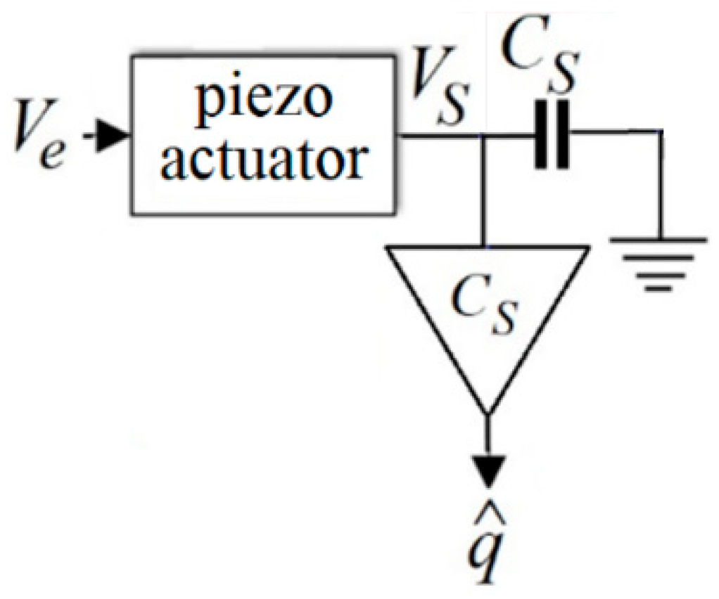
Figure 5 is a simplified schematic of a charge estimator inspired by the pioneering work in [43], published in 1981, where the sensing element is the capacitor of CS. As VS is not applied on the actuator, it is also known as the voltage drop.
Equation (1) presents VS, the voltage across the sensing capacitor of CS, in the Laplace domain:
where IS is the current passing the sensing capacitor. The voltage amplifier (the triangle) is not grounded; thus, only a tiny current passes through it. Therefore, IS is nearly equal to the current passing the piezoelectric actuator, IP:
where q is the charge of the piezoelectric actuator and s is the Laplace variable. Combination of (1) and (2) shows that VS, amplified by a voltage amplifier with a gain of CS, can estimate the charge:
IS ≈ IP = qs,
Nevertheless, the estimated charge may not equal q. In fact, dielectric leakage of the piezoelectric actuator generates a low frequency (nearly DC) and minuscule voltage [37]. This voltage and other sources within the circuit make a nearly fixed current, Ib, not included in Equations (1) and (3). Ib is added to IP and is integrated by the sensing capacitor [39]:
Comparison of (3) and (4) results in (5):
Equations (4) and (5) show that, owing to the integration of Ib, the estimated charge presented in (3) and Figure 5 ramps away the real charge of the piezoelectric actuator, q. This phenomenon is named ‘drift’ and has been observed since the emergence of charge estimators for piezoelectric actuators [38,43]. Two drift removal methods have been reported in the literature for type I charge estimators, initialisation circuits, and analogue high-pass filters, resulting in two sub-types of type I charge estimators.
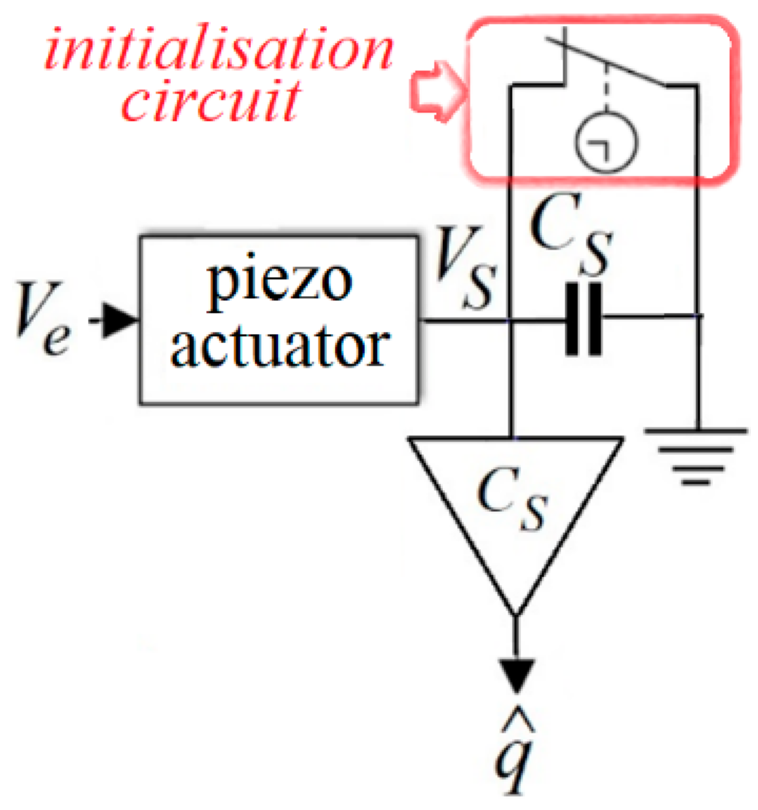
3.1.1. Type IA—Type I with an Initialisation Circuit
Early type I charge estimators had an initialisation circuit to curb drift. These estimators are categorised as type IA in this paper. An initialisation circuit, as depicted in Figure 6, simply short circuits the sensing capacitor in sub-second periods to interrupt the integration of the fixed current [39]. Figure 4 in [43], a front-runner work, presents an initialisation circuit including a timer and a switch, fairly similar to Figure 6, capable of open-loop charge estimation. Figure 7 in [38], published in 1995, presents a more intricate initialisation circuit including current buffers. Both initialisation circuits reported in [38,43] discharge the sensing capacitor every 400 ms, i.e., with a frequency of 2.5 Hz. Therefore, charge estimators with these circuits cannot capture any charge signal with a frequency lower than two times the switching frequency or 5 Hz [44]. As another disadvantage, all initialisation circuits include switches; hence, they suffer from high-frequency parasitic voltages [37].
3.1.2. Type IB—Type I with an Analogue High-Pass Filter
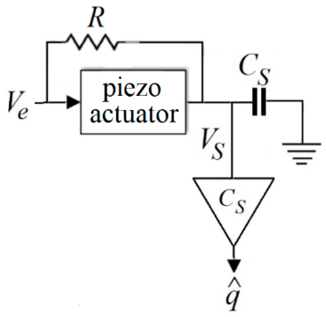
As an alternative to an initialisation circuit, in 2004, a resistor of R was used in parallel with an actuator [39], as depicted in Figure 7.
A piezoelectric actuator, from an electrical viewpoint, behaves almost like a capacitor with a capacitance of CP [41]. As to Figure 7, the voltage across R is same as the voltage across the actuator, as presented in (6), since they are in parallel.
where IR is the current passing R. Noting that (i) the current passing the amplifier is negligible, (ii) IP = qs and (6), both (7) and (8) present IS; the current passing the sensing capacitor is shown in (7).
IS = VS CS s.
Equations (7) and (8) lead to (9):
Equation (9) has an additional high-pass filter compared with (3). Type I estimators with such a filter are categorised as Type IB estimators in this paper. The presented high-pass filter with a cut-off frequency of (CPR)−1 rad/s restrains the DC (or very low-frequency) current of Ib, presented in (5). As a drawback, the filter suppresses other low-frequency components; consequently, these estimators may not capture low-frequency charge signals.
3.2. Type II—Charge Estimators with a Sensing Resistor
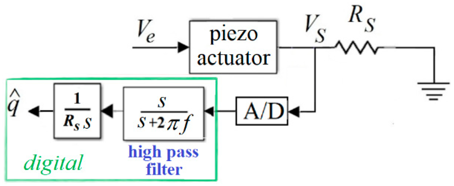
As to (3), the main role of the sensing capacitor in type I estimators is to add an integrator to make the sensing voltage proportional to the actuator’s charge (rather than current). Such an integration, however, may happen within a digital processor with no need for a capacitor, as proposed in 2010 [40]. Figure 8 depicts a type II charge estimator with a sensing resistor, where A/D stands for analogue to digital converter.
The current going towards A/D is tiny; hence, the current passing through the sensing resistor nearly equals IP, the current passing the piezoelectric actuator. As a result, (10) presents the voltage across the sensing resistor:
VS ≃ IP RS.
Equations (2) and (10) lead to (11):
However, as mentioned in Section 3.1, dielectric leakage of the piezoelectric actuator generates a minuscule low-frequency (nearly DC) voltage [27]. This voltage, added by A/D offset voltage, forms a nearly DC voltage, Vb, not considered in (10) and (11) [45]. In other words, VS + Vb enters the digital processor in reality rather than VS. Therefore,
That is, drift (integration of a minute DC signal over time) occurs in type II charge estimators as well. The role of the high-pass filter in Figure 8 is to suppress low-frequency voltage components before integration and curb drift, where f is the cutting frequency of the high-pass filter in Hz.
4. Problem Statement
As explained in Section 3, type IA charge estimators, having switch(es), witness high-frequency parasitic voltages; thus, they are no longer considered comparably viable. The more promising estimator types, IB and II, still have two main drawbacks:
- The high-pass filter distorts low-frequency charge signals.
- The voltage across the sensing element, known as voltage drop, is not exerted on the actuator and is practically wasted.
The first drawback can be appropriately tackled with the use of a weighted filter or a data fusion algorithm. With this approach, in low-frequency areas of operating, charge is estimated through a process of VS with a data-driven model, and the methods depicted in Figure 7 and Figure 8 are used for high-frequency operating areas only, as described in [22,48]. This approach can be employed for both type IB and II charge estimators. Therefore, this drawback will not be further investigated in the paper.
The second drawback, voltage drop, is the remaining decisive matter in the choice of charge estimator type. Depending on the equipment employed, a certain value of voltage drop, VS, is required for charge estimation without loss of accuracy, as detailed in [26]. An important question is how much charge can be estimated with this inevitable voltage drop in two comparable type IB and II charge estimators.
Experimental results, reported in [49], indicate that a type II estimator witnesses a significantly smaller voltage drop compared with a type IB one to estimate the same amount of charge. This conclusion can be reasonably rephrased as ‘with the same voltage drop, type II estimators can estimate a much larger amount of charge than type IB ones’. Therefore, it was concluded that type II estimators meaningfully outperform type IB ones in terms of voltage drop [37]. As a result, recent research in the area of charge estimation of piezoelectric actuators is mainly focused on type II (digital) charge estimators [46,47].
This paper questions the superiority of type II charge estimators, demonstrated by the experimental results of [49]. The key point is that the sensing element, either the capacitor in type IB or the resistor in type II (digital) estimators, has been chosen intuitively in both type IB (e.g., [39,50]) and type II (e.g., [27,49]) estimators. Therefore, no general conclusion can be drawn from their comparison.
In this paper, type IB and type II charge estimators are analytically designed so that both result in a voltage drop with an amplitude of 1 V for a number of sinusoidal excitation voltages. Then, they are analytically and experimentally compared in terms of their estimated charge and other performance factors identified in this thorough comparison. In this paper, term ‘design’ mainly refers to the choice of the sensing component.
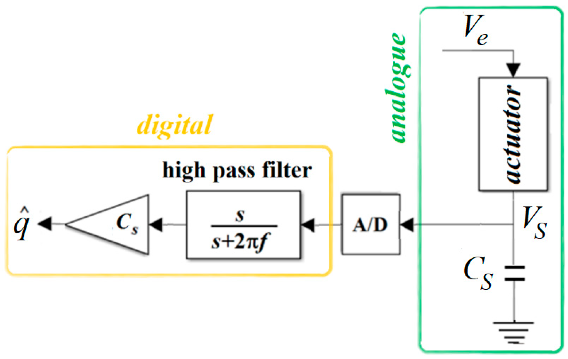
In order to make an equitable comparison, this article proposes a new version of type IB estimators, depicted in Figure 9, with a digital gain instead of the amplifier and a digital high-pass filter instead of the resistor shown in Figure 7. This proposed estimator, in terms of implementation, is well comparable to the type II estimators depicted in Figure 8.
5. Analytical Investigation
This section presents an approximate analytical formulation of type I and II charge estimators, depicted in Figure 8 and Figure 9, respectively. The primary goal is to suggest the sensing capacitance/resistance values to produce certain voltage drop amplitudes for both type I and II estimators. In this section, high-pass filters are disregarded, as their influence is significant only in low-frequency operating areas. Moreover, the tiny current going to A/D is also neglected. In addition, as already mentioned in Section 3.1.2, the piezoelectric actuator is approximated by a capacitor, CP [49].
5.1. Analytical Formulation for Type I Charge Estimators
With the aforementioned assumptions, in Figure 9, the piezoelectric actuator and the sensing capacitor are in series; (13) and (14) present their equivalent impedance, Z, and the current passing the actuator, IP:
Using (14), (15) approximates the voltage drop, VS:
As for (15), VS is proportional to the excitation voltage, Ve; therefore, a bias (time independent component) in Ve leads to a bias in VS. In addition, considering Ae and AS as the amplitudes of sinusoidal Ve and VS, respectively, (15) leads to (16):
5.2. Analytical Formulation for Type II Charge Estimators
For the system depicted in Figure 8, with assumptions presented at the beginning of Section 5, (17)–(19) replace (13)–(15):
For the approximate linear system presented in (19), a sinusoidal excitation voltage without a bias, Ve = Ae sin ωt, leads to a sensing voltage (also known as the voltage drop) of
VS = AS [sin ωt + 0.5π − arctan (RSCP)] ≈ AS cos ωt.
Based on (19), the amplitudes of Ve and VS, AS, and Ae have the following relationship:
For a sinusoidal excitation voltage with a bias of B, i.e., Ve = Ae sin ωt + B, since (19) is linear, superposition may be used, and the sensing voltage, VS, can be assumed as the sum of two components influenced by Ae sin ωt and B (bias or time-independent excitation). The final value of the component of VS influenced by B, VSB, is shown to be zero in (22):
That is, excitation bias has no enduring effect in a type II charge estimator for piezoelectric actuators. This agrees with the experimental results reported in [45].
5.3. Results of Approximate Analytical Investigation
Based on the formulation presented in Section 5.1 and Section 2, it is possible to find approximate sensing capacitance/resistance in type I/II estimators, leading to a certain voltage drop amplitude, AS, for any given sinusoidal excitation voltage.
In type I estimators, as to (16), in order to achieve a voltage drop amplitude of AS, for a given excitation voltage amplitude of Ae, the sensing capacitor should be selected according to (23):
According to (15), a sinusoidal excitation voltage leads to a sinusoidal voltage drop. In this case, q = CS VS = CS AS sin ωt. Thus,
where qrange-I is the range of charge with a type I estimator in the case of a voltage drop amplitude of AS.
qrange-I = 2CS AS,
In type II estimators, with the use of (10) and (20):
In addition, based on (21), (26) defines the sensing resistor, which leads to AS:
(25) and (26) lead to
Assuming Ae ≫ 1 in Equations (16) and (27), Equation (28) can be derived to increase the comparability of type I and II estimators. In fact, the charge range of a type II estimator with resistance calculated with (26) is presented with a formula based on a capacitance calculated with (23):
qrange-II = 2(CS + CP) AS.
The Section 5 findings can be summarised as follows:
- Theoretically, (23)/(26) can calculate the sensing capacitance/resistance leading to a sinusoidal voltage drop with an amplitude of AS with a type I/II charge estimator, respectively, where Ae is the amplitude of the sinusoidal excitation voltage.
- Based on (23) and (26), the sensing capacitance/resistance of type I/II estimators is dependent on/independent of the excitation frequency. This is a merit for type I estimators.
- A fixed component (bias) in excitation voltage leads to a fixed component voltage drop in type I estimators, as per (15) and superposition. Such a component (bias) has no enduring effect on the voltage drop in type II estimators, per (22).
- For an identical voltage drop, according to (24) and (28), type II estimators estimate a larger charge compared with type I ones, assuming Ae ≫ 1. However, considering the values of CS and CP reported in experiments, the difference in estimated charge is insubstantial.
6. Experimentation
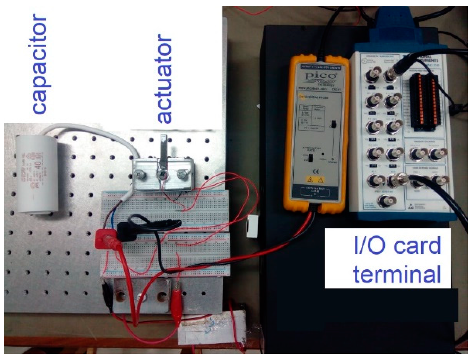
Figure 10 partly depicts the experimental setup, the implementation of Figure 9. The same setup was used to implement Figure 8 with change of the capacitor to a resistor. f, the cutting frequency of the high-pass filter, is 5 Hz. A personal computer with an Intel Core i7-2600 @ 3.4 GHz CPU and a 12 GB RAM plays the role of the digital processor. The digital parts of Figure 8 and Figure 9 were implemented with use of MATLAB 9.1/Simulink 8.8 software. Simulink Real-Time Desktop Toolbox 5.3 was used to transfer the voltage signal to the computer through the A/D of a PCIe-6323 National Instruments multifunctional card. The actuator was a 7 × 7 × 42 mm3 piezoelectric stack, with epoxy coating and the code of SA070742 detailed in [51]. The actuator had a stiffness of 51 N/μm and capacitance, CP, of 6.23 µF, measured with an LCR meter at the amplitude of 1 V and the frequency of 1 kHz. Ve, the excitation voltage in Figure 8 and Figure 9, was originally generated in Simulink then transferred to an AETECHRON 7114 liner power amplifier through the Simulink Real-Time Desktop Toolbox and the PCIe-6323 card.
As mentioned in Section 4 and Section 5, the excitation voltages follow the equation of Ve = Ae sin ωt; excitation frequency in Hz is defined as
fe = ω/2π.
Experiments aimed to realise AS = 1 V, as mentioned in the problem statement, based on approximate formulae derived in Section 5. In type I estimators, with the use of (16), for the sensing capacitors of 20, 40, and 80 µF, the theoretical Ae values would be 4.21, 7.42, and 13.84 V, respectively. A sinusoidal excitation voltage with each of these values of amplitude was applied on a setup with its respective sensing capacitor. Excitation frequency, fe, had the values of 20, 30, 40, 50, 60, and 70 Hz for every pair of capacitors and Ae. This means 18 experiments were performed to assess type I estimators. Similar experiments, with the same values of Ae, were carried out for type II estimators; however, for each excitation frequency, the sensing resistance was calculated based on (26). In all experiments, the ranges of charge, qrange, and AS (practically half of VS range) were measured. A sample time of 10−4 s was used in all experiments. As an implementation point, the employed capacitors, e.g., the one shown in Figure 10, were bulkier than the resistors/potentiometer used.
7. Experimental Results and Discussion
With use of AS = 1 V, (23) and (26) lead to RS and CS, shown in (30) and (31).
According to the approximate analytical formulation presented in Section 5, sensing capacitance/resistance calculated with (30) and (31) should result in a sensing voltage amplitude (AS) of 1 V and the range of charge presented in (32) and (33) for any given sinusoidal excitation voltage with the amplitude of Ae. (32) and (33) are the results from AS = 1 and (24) and (28). In summary, with RS and CS determined with (30) and (31), the following approximate theoretical outcomes are expected:
AS = 1 V
qrange-I = 2CS.
qrange-II = 2(CS + CP).
Table 1, Table 2 and Table 3 present the experimental results and their comparison with the aforementioned theoretical expectations of the approximate analytical formulation. The following are three major observations from these data:
7.1. Observation 1: Discrepancy between Estimator Types in Frequency Dependency
For each value of Ae presented in Table 1, Table 2 and Table 3, the voltage drop amplitude for type I estimators, AS-I, and their range of charge, qrange-I, are nearly fixed across different excitation frequencies, fe. This is in agreement with finding (2) in Section 5, presented in (16), and is a substantial advantage. On the other hand, in type II estimators, for the higher values of Ae presented in Table 2 and Table 3, AS-II and qrange-II decrease meaningly with an increase in fe; however, the resistor changes with frequency according to (31) to maintain AS at 1 V.

Table 1.
Experimental results for the excitation voltage amplitude of 4.21 V. Indices I and II refer to type I and II estimators.
Table 1.
Experimental results for the excitation voltage amplitude of 4.21 V. Indices I and II refer to type I and II estimators.
| Ae = 4.21 V, CS = 20 μF qrange-I-analytical = 40 μC, qrange-II-analytical = 52.46 μC | |||||
|---|---|---|---|---|---|
| fe (Hz) | R (Ω) | AS-I (V) | AS-II (V) | qrange-I (μC) | qrange-II (μC) |
| 20 | 303 | 1.10 | 0.99 | 44.14 | 53.07 |
| 30 | 202 | 1.10 | 1.00 | 44.08 | 54.62 |
| 40 | 152 | 1.10 | 1.00 | 44.01 | 54.35 |
| 50 | 121 | 1.10 | 1.02 | 43.88 | 54.19 |
| 60 | 101 | 1.10 | 0.97 | 43.94 | 52.77 |
| 70 | 87 | 1.10 | 0.96 | 43.94 | 53.64 |
Table 2.
Experimental results for the excitation voltage amplitude of 7.42 V. Indices I and II refer to type I and II estimators.
Table 2.
Experimental results for the excitation voltage amplitude of 7.42 V. Indices I and II refer to type I and II estimators.
| Ae = 7.42 V, CS = 40 μF qrange-I-analytical = 80 μC, qrange-II-analytical = 92.45 μC | |||||
|---|---|---|---|---|---|
| fe (Hz) | R (Ω) | AS-I (V) | AS-II (V) | qrange-I (μC) | qrange-II (μC) |
| 20 | 172 | 1.16 | 1.05 | 92.49 | 99.30 |
| 30 | 115 | 1.16 | 1.04 | 92.49 | 99.88 |
| 40 | 86 | 1.15 | 0.99 | 92.36 | 92.68 |
| 50 | 69 | 1.16 | 0.94 | 92.62 | 88.30 |
| 60 | 57 | 1.15 | 0.92 | 92.36 | 87.25 |
| 70 | 49 | 1.14 | 0.83 | 91.05 | 82.96 |
Table 3.
Experimental results for the excitation voltage amplitude of 13.84 V. Indices I and II refer to type I and II estimators.
Table 3.
Experimental results for the excitation voltage amplitude of 13.84 V. Indices I and II refer to type I and II estimators.
| Ae = 13.84 V, CS = 80 μF qrange-I-analytical = 160 μC, qrange-II-analytical = 172 μC | |||||
|---|---|---|---|---|---|
| fe (Hz) | R (Ω) | AS-I (V) | AS-II (V) | qrange-I (μC) | qrange-II (μC) |
| 20 | 92 | 1.30 | 1.14 | 207.6 | 204.2 |
| 30 | 62 | 1.29 | 1.07 | 206.3 | 1 97.8 |
| 40 | 46 | 1.29 | 1.00 | 206.0 | 193.0 |
| 50 | 37 | 1.28 | 0.99 | 205.3 | 194.8 |
| 60 | 31 | 1.28 | 0.87 | 204.7 | 177.7 |
| 70 | 26 | 1.28 | 0.81 | 204.5 | 168.8 |
7.2. Observation II: Discrepancy between Theoretically Expected and Experimental Values of AS
The real values of AS, in most experiments, are not equal to 1 V, despite theoretical expectations. This discrepancy simply means if (23) and (26) are trusted to find the capacitance/resistance of sensing components, an unexpected value of AS may happen to exist. Particularly, overly high values of AS may lead to serious issues as detailed in subsection VII.C of [26].
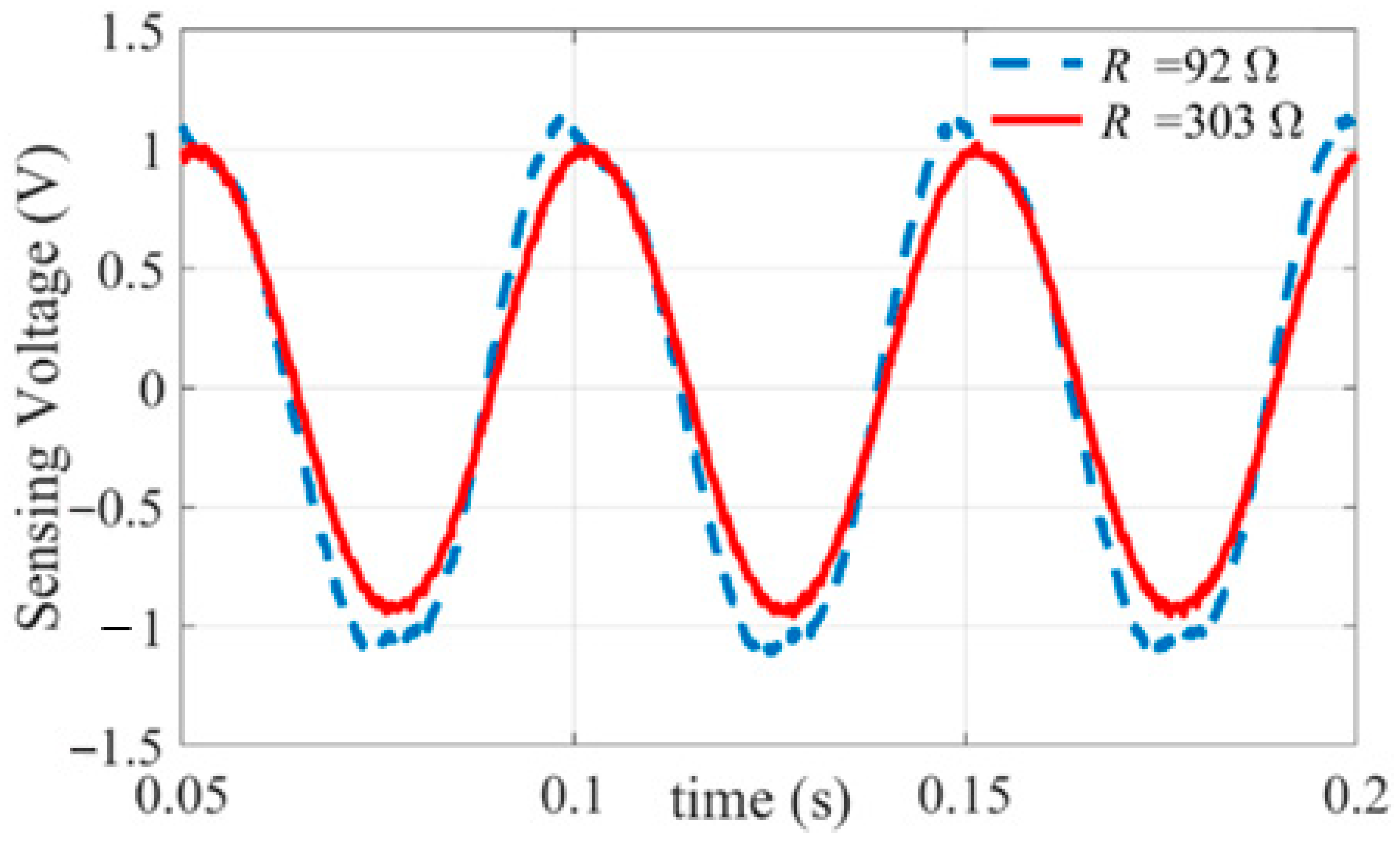
A partial reason for the difference between the theoretical approximate expectations and the experimental results is neglected nonlinearities. For instance, for type II estimators, based on the linearity of (19), it is expected that with a sinusoidal excitation voltage, Ve, a sinusoidal sensing voltage, VS, will be observed. Figure 11 depicts VS for two type II estimators both designed per (31) and excited with a sinusoidal voltage to assess this expectation. For the estimator designed for a higher amplitude of excitation voltage (Ae), VS is not sinusoidal, as shown by the dashed curve in Figure 11, relevant to the shaded cell in Table 3; this demonstrates nonlinearity, which has been overlooked in the analytical formulation. However, VS for the other type II estimator, shown by a solid curve in Figure 11, relevant to the shaded cell of Table 1, is nearly sinusoidal. This indicates that nonlinearity is inapparent in some operating areas.
The mean values of the discrepancy between theoretically expected and experimental AS for type II estimators in Table 1, Table 2 and Table 3 are 0.0167 V, 0.0683 V, and 0.09 V, respectively. These values are obviously larger for type I estimators, 0.1 V, 0.1533 V, and 0.2867 V. However, the discrepancy can be avoided more simply in type I, as it is almost independent of frequency. By the way, the aforementioned discrepancy is no longer a major issue in terms of design, i.e., finding RS and CS values to realise a certain value of AS. Data-driven methods, based on artificial intelligence and statistics, are available to replace (23) and (26) in the design of estimators to assure AS remains in a safe zone with no or minor loss to the accuracy of charge estimation [26]. Those data-driven methods, nevertheless, provide no physical insight compared with analytical formulation.
7.3. Observation III: Type II Estimators Are Capable of Estimating Slightly Higher Values of Charge
The last observation is that a Type II estimator can estimate higher values of charge compared with type I estimators, with the same sensing voltage (voltage drop). This observation is in agreement with finding (4) of analytical formulation in Section 5, which is the outcome of comparison of (24) with (28) or (32) with (33). The results presented in Table 1, Table 2 and Table 3 are not straightforwardly usable for this observation, as the experimental values of AS are different for type I and II estimators, particularly in Table 3. Table 4, alternatively, eases the comparison. This table shows that for the same amplitude of voltage drop (AS), a type II estimator estimates a 12% to 40% higher amount of charge than a type I estimator for the setup and conditions detailed in Section 6. However, this discrepancy is not as substantial as presented in the experimental results reported in [49]. For instance, for an excitation frequency of 10 Hz, the result in Table 2 of [49] can be reasonably interpreted as showing that type II estimators can estimate 892% more charge than type I ones with the same AS. Such results have been used as a ground for the superiority of type II estimators. The point is that the method of design (choice of sensing resistance/capacitance) in [49] is not backed by an analytical formulation; hence, the experiments were practically carried out with intuitively chosen values of RS and CS.
8. Conclusions
This paper first briefly reviewed position control, specially sensorless position control, of piezoelectric actuators and highlighted its core role in micro/nanopositioning. Then, charge-based sensorless control systems, particularly their main component charge estimators, were introduced. Then, through analytical formulation and experiments, the paper compared the most recent/effective types of charge estimators for piezoelectric actuators: estimators with a sensing capacitor, named type I, and estimators with a sensing resistor, named type II in this paper. The latter is also known as a digital estimator. In order to make an even-handed comparison, a digital version of a type I estimator, depicted in Figure 9, was developed and implemented.
In both type I and II estimators, a portion of the excitation voltage is squandered for charge estimation and does not apply to the actuator; this loss in voltage is called voltage drop. Comparative experimental results in the literature demonstrate that, with the same voltage drop, type II estimators can estimate significantly higher charge than type I estimators in similar operating conditions. As a result, type II estimators were widely considered superior in the last decade. This paper presented a thorough analytical and experimental comparative study to assess the claimed superiority of type II estimators in terms of voltage drop and other aspects for a piezoelectric stack actuator detailed in Section 6. The following are the main conclusions of this study:
- C1.
- Type II estimators have a slightly higher ratio of estimated charge to voltage drop, 12% to 40%, according to experiments.
- C2.
- Both behaviour and the choice of the sensing element are independent of/dependent on frequency in type I/II estimators, as a major advantage of type I estimators.
- C3.
- Bias (a time-independent component) in the excitation voltage has an/no enduring effect on the behaviour of type I/II estimators.
- C4.
- In type I estimators, in order to obtain low voltage drops, high-capacitance sensing capacitors need to be employed. These capacitors are bulkier than the resistors used in type II estimators. Such a capacitor is shown in Figure 10.
- C5.
- Type I estimators can be implemented as an analogue circuit, e.g., Figure 7; while type II estimators need digital processors to be implemented.
In summary, either a type I or type II estimator may be the best existing charge estimation solution for a piezoelectric actuator for a specific application, and none of these types should be abandoned.
Author Contributions
Conceptualization, M.M.; methodology, M.M. and M.G.; Experiments, S.A.-S.; Analytical Formulation, M.M., M.G. and P.S.; writing—original draft preparation, M.M., S.A.-S., M.G. and P.S.; writing—review and editing, M.M.; visualization, M.M. and S.A.-S.; supervision, M.M. All authors have read and agreed to the published version of the manuscript.
Funding
This research received no external funding.
Data Availability Statement
All experimental data are available to disseminate upon request to the corresponding author.
Conflicts of Interest
The authors declare no conflict of interest.
References
- Sabek, W.; Al-mana, A.; Siddiqui, A.R.; Assadi, B.E.; Mohammad-khorasani, M.; Mohammadzaheri, M.; Tafreshi, R. Experimental Investigation of Piezoelectric Tube Actuators Dynamics. In Proceedings of the 2nd International Conference on Robotics and Mechatronics, Madrid, Spain, 20–21 July 2015. [Google Scholar]
- Hoshyarmanesh, H.; Ghodsi, M.; Kim, M.; Cho, H.H.; Park, H.-H. Temperature Effects on Electromechanical Response of Deposited Piezoelectric Sensors Used in Structural Health Monitoring of Aerospace Structures. Sensors 2019, 19, 2805. [Google Scholar] [CrossRef] [PubMed]
- Hoshyarmanesh, H.; Ghodsi, M.; Park, H.-H. Electrical Properties of Uv-Irradiated Thick Film Piezo-Sensors on Superalloy In718 Using Photochemical Metal Organic Deposition. Thin Solid Film. 2016, 616, 673–679. [Google Scholar] [CrossRef]
- Hoshyarmanesh, H.; Nehzat, N.; Salehi, M.; Ghodsi, M.; Lee, H.-S.; Park, H.-H. Piezoelectric Transducers on Curved Dispersive Bending Wave and Poke-Charged Touch Screens. Mater. Manuf. Process. 2014, 29, 870–876. [Google Scholar] [CrossRef]
- Chopra, I. Review of State of Art of Smart Structures and Integrated Systems. Aiaa J. 2002, 40, 2145–2187. [Google Scholar] [CrossRef]
- Rios, S.; Fleming, A. Control of Piezoelectric Benders Using a Charge Drive. In Proceedings of the 14th International Conference on New Actuators, Beremen, Germany, 23–25 June 2014. [Google Scholar]
- Delibas, B.; Koc, B.; Thielager, J.; Stiebel, C. A Novel Drive and Control Method for Piezoelectric Motors in Microscopy Stages. In Proceedings of the Euspen’s 21st International Conference & Exhibition, Copenhagen, Denmark, 7–10 June 2021. [Google Scholar]
- Hou, W.; Zheng, Y.; Guo, W.; Pengcheng, G. Piezoelectric Vibration Energy Harvesting for Rail Transit Bridge with Steel-Spring Floating Slab Track System. J. Clean. Prod. 2021, 291, 125283. [Google Scholar] [CrossRef]
- Sharma, K.; Srinivas, G. Flying Smart: Smart Materials Used in Aviation Industry. J. Mater. Today Proc. 2020, 27, 244–250. [Google Scholar] [CrossRef]
- Li, H.; Liu, J.; Li, K.; Liu, Y. Piezoelectric Micro-Jet Devices: A Review. Sens. Actuators A Phys. 2019, 297, 111552. [Google Scholar] [CrossRef]
- Singh, K.; Sharma, S.; Kumar, R.; Talha, M. Vibration Control of Cantilever Beam Using Poling Tuned Piezoelectric Actuator. Mech. Based Des. Struct. Mach. 2021, 51, 2217–2240. [Google Scholar] [CrossRef]
- Flores, G.; Rakotondrabe, M. Robust Nonlinear Control for a Piezoelectric Actuator in a Robotic Hand Using Only Position Measurements. IEEE Control Syst. Lett. 2021, 6, 872–877. [Google Scholar] [CrossRef]
- Mohammadzaheri, M.; Soltani, P.; Ghodsi, M. Micro/Nanopositioning Systems with Piezoelectric Actuators and Their Role in Sustainability and Ecosystems. In EcoMechatronics: Challenges for Evolution, Development and Sustainability; Springer: Berlin/Heidelberg, Germany, 2022; pp. 233–250. [Google Scholar]
- Moheimani, S.O.R. Invited Review Article: Accurate and Fast Nanopositioning with Piezoelectric Tube Scanners: Emerging Trends and Future Challenges. Rev. Sci. Instrum. 2008, 79, 071101. [Google Scholar] [CrossRef]
- Mohammadzaheri, M.; AlQallaf, A. Nanopositioning Systems with Piezoelectric Actuators, Current State and Future Perspective. Sci. Adv. Mater. 2017, 9, 1071–1080. [Google Scholar] [CrossRef]
- Hu, C.; Shi, Y.; Liu, F. Research on Precision Blanking Process Design of Micro Gear Based on Piezoelectric Actuator. Micromachines 2021, 12, 200. [Google Scholar] [CrossRef] [PubMed]
- Deng, J.; Liu, S.; Liu, Y.; Wang, L.; Gao, X.; Li, K. A 2-Dof Needle Insertion Device Using Inertial Piezoelectric Actuator. IEEE Trans. Ind. Electron. 2021, 69, 3918–3927. [Google Scholar] [CrossRef]
- Szeremeta, W.K.; Harniman, R.L.; Bermingham, C.R.; Antognozzi, M. Towards a Fully Automated Scanning Probe Microscope for Biomedical Applications. Sensors 2021, 21, 3027. [Google Scholar] [CrossRef]
- Meinhold, W.; Martinez, D.E.; Oshinski, J.; Hu, A.-P.; Ueda, J. A Direct Drive Parallel Plane Piezoelectric Needle Positioning Robot for Mri Guided Intraspinal Injection. IEEE Trans. Biomed. Eng. 2020, 68, 807–814. [Google Scholar] [CrossRef] [PubMed]
- Miri, N.; Mohammadzaheri, M.; Chen, L. An Enhanced Physics-Based Model to Estimate the Displacement of Piezoelectric Actuators. J. Intell. Mater. Syst. Struct. 2015, 26, 1442–1451. [Google Scholar] [CrossRef]
- Yi, K.; Veillette, R. A Charge Controller for Linear Operation of a Piezoelectric Stack Actuator. IEEE Trans. Control Syst. Technol. 2005, 13, 517–526. [Google Scholar] [CrossRef]
- Bazghaleh, M.; Grainger, S.; Mohammadzaheri, M.; Cazzolato, B.; Lu, T.-F. A Novel Digital Charge-Based Displacement Estimator for Sensorless Control of a Grounded-Load Piezoelectric Tube Actuator. Sens. Actuators A Phys. 2013, 198, 91–98. [Google Scholar] [CrossRef]
- Soleymanzadeh, D.; Ghafarirad, H.; Zareinejad, M. Charge-Based Robust Position Estimation for Low Impedance Piezoelectric Actuators. Measurement 2019, 147, 106839. [Google Scholar] [CrossRef]
- Mohammadzaheri, M.; Ziaiefar, H.; Ghodsi, M.; Bahadur, I.; Zarog, M.; Saleem, A.; Emadi, M. Adaptive Charge Estimation of Piezoelectric Actuators, a Radial Basis Function Approach. In Proceedings of the 20th International Conference on Research and Education in Mechatronics, Wels, Austria, 23–24 May 2019. [Google Scholar]
- Mohammadzaheri, M.; AlSulti, S.; Ghodsi, M.; Bahadur, I.; Emadi, M. Assessment of Capacitor-Based Charge Estimators for Piezoelectric Actuators. In Proceedings of the IEEE International Conference on Mechatronics, Kashiwa, Japan, 7–9 March 2021. [Google Scholar]
- Mohammadzaheri, M.; Ziaiefar, H.; Ghodsi, M.; Emadi, M.; Zarog, M.; Soltani, P.; Bahadur, I. Adaptive Charge Estimation of Piezoelectric Actuators with a Variable Sensing Resistor, an Artificial Intelligence Approach. Eng. Lett. 2022, 30, 193–200. [Google Scholar]
- Bazghaleh, M.; Mohammadzaheri, M.; Grainger, S.; Cazzolato, B.; Lu, T.F. A New Hybrid Method for Sensorless Control of Piezoelectric Actuators. Sens. Actuators A Phys. 2013, 194, 25–30. [Google Scholar] [CrossRef]
- Roshandel, N.; Soleymanzadeh, D.; Ghafarirad, H.; Koupaei, A.S. A Modified Sensorless Position Estimation Approach for Piezoelectric Bending Actuators. Mech. Syst. Signal Process. 2021, 149, 107231. [Google Scholar] [CrossRef]
- Mohammadzaheri, M.; Grainger, S.; Kopaei, M.K.; Bazghaleh, M. Imc-Based Feedforward Control of a Piezoelectric Tube Actuator. In Proceedings of the IEEE Eighth International Conference on Intelligent Sensors, Sensor Networks and Information Processing, Melbourne, VIC, Australia, 2–5 April 2013. [Google Scholar]
- Miri, N.; Mohammadzaheri, M.; Chen, L. A Comparative Study of Different Physics-Based Approaches to Modelling of Piezoelectric Actuators. In Proceedings of the IEEE/ASME International Conference on Advanced Intelligent Mechatronics, Wollongong, NSW, Australia, 9–12 July 2013. [Google Scholar]
- Mohammadzaheri, M.; Ziaeifar, H.; Bahadur, I.; Zarog, M.; Emadi, M.; Ghodsi, M. Data-Driven Modelling of Engineering Systems with Small Data, a Comparative Study of Artificial Intelligence Techniques. In Proceedings of the 5th Iranian Conference on Signal Processing and Intelligent Systems (ICSPIS), Semnan, Iran, 18–19 December 2019. [Google Scholar]
- Ahmadpour, H.; Mohammadzaheri, M.; Emadi, M.; Ghods, V.; Mehrabi, D.; Tafreshi, R. Neural Modelling of a Piezoelectric Actuator Inspired by the Presiach Approach. In Proceedings of the International Conference on Artificial Intelligence, Energy and Manufacturing Engineering, Dubai, United Arab Emirates, 7–8 January 2015. [Google Scholar]
- Mohammadzaheri, M.; Grainger, S.; Bazghaleh, M. A System Identification Approach to the Characterization and Control of a Piezoelectric Tube Actuator. Smart Mater. Struct. 2013, 22, 105022. [Google Scholar] [CrossRef]
- Mohammadzaheri, M.; Grainger, S.; Bazghaleh, M. A Comparative Study on the Use of Black Box Modelling for Piezoelectric Actuators. Int. J. Adv. Manuf. Technol. 2012, 63, 1247–1255. [Google Scholar] [CrossRef]
- Mohammadzaheri, M.; Grainger, S.; Bazghaleh, M. Fuzzy Modeling of a Piezoelectric Actuator. Int. J. Precission Eng. Manuf. 2012, 13, 663–670. [Google Scholar] [CrossRef]
- Qin, Y.; Tian, Y.; Zhang, D.; Shirinzadeh, B.; Fatikow, S. A Novel Direct Inverse Modeling Approach for Hysteresis Compensation of Piezoelectric Actuator in Feedforward Applications. IEEE/ASME Trans. Mechatron. 2012, 18, 981–989. [Google Scholar] [CrossRef]
- Bazghaleh, M.; Grainger, S.; Mohammadzaheri, M. A Review of Charge Methods for Driving Piezoelectric Actuators. J. Intell. Mater. Syst. Struct. 2018, 29, 2096–2104. [Google Scholar] [CrossRef]
- Main, J.A.; Garcia, E.; Newton, D.V. Precision Position Control of Piezoelectric Actuators Using Charge Feedback. J. Guid. Control Dyn. 1995, 18, 1068–1073. [Google Scholar] [CrossRef]
- Fleming, A.J.; Moheimani, R. Improved Current and Charge Amplifiers for Driving Piezoelectric Loads, and Issues in Signal Processing Design for Synthesis of Shunt Damping Circuits. J. Intell. Mater. Syst. Struct. 2004, 15, 77–92. [Google Scholar] [CrossRef]
- Bazghaleh, M.; Grainger, S.; Cazzolato, B.; Lu, T.-F. An Innovative Digital Charge Amplifier to Reduce Hysteresis in Piezoelectric Actuators. In Proceedings of the Australian Robotics and Automation Association (ACRA), Brisbane, Australia, 1–3 December 2010. [Google Scholar]
- Newcomb, C.V.; Flinn, I. Improving the Linearity of Piezoelectric Ceramic Actuators. Electron. Lett. 1982, 18, 442–444. [Google Scholar] [CrossRef]
- Huang, L.; Ma, Y.T.; Feng, Z.H.; Kong, F.R. Switched Capacitor Charge Pump Reduces Hysteresis of Piezoelectric Actuators over a Large Frequency Range. Rev. Sci. Instrum. 2010, 81, 094701. [Google Scholar] [CrossRef] [PubMed]
- Comstock, R.H. Charge Control of Piezoelectric Actuators to Reduce Hysteresis Effects. U.S. Patent 4,263,527, 21 April 1981. [Google Scholar]
- Landau, I.D.; Zito, G. Digital Control Systems; Springer: London, UK, 2006. [Google Scholar]
- Mohammadzaheri, M.; Emadi, M.; Ghodsi, M.; Bahadur, I.M.; Zarog, M.; Saleem, A. Development of a Charge Estimator for Piezoelectric Actuators: A Radial Basis Function Approach. Int. J. Artif. Intell. Mach. Learn. (IJAIML) 2020, 10, 31–44. [Google Scholar] [CrossRef]
- Zhong, J.; Nishida, R.; Shinshi, T. A Digital Charge Control Strategy for Reducing the Hysteresis in Piezoelectric Actuators: Analysis, Design, and Implementation. Precis. Eng. 2021, 67, 370–382. [Google Scholar] [CrossRef]
- Mohammadzaheri, M.; Ziaiefar, H.; Ghodsi, M. Digital Charge Estimation for Piezoelectric Actuators: An Artificial Intelligence Approach. In Handbook of Research on New Investigations in Artificial Life, Ai, and Machine Learning; IGI Global: Hershey, PA, USA, 2022; pp. 117–140. [Google Scholar]
- Bazghaleh, M.; Grainger, S.; Cazzolato, B.; Lu, T. Using Frequency-Weighted Data Fusion to Improve the Performance of a Digital Charge Amplifier. In Proceedings of the IEEE International Conference on Robotics and Automation, Saint Paul, MN, USA, 14–18 May 2012. [Google Scholar]
- Bazghaleh, M.; Grainger, S.; Mohammadzaheri, M.; Cazzolato, B.; Lu, T. A Digital Charge Amplifier for Hysteresis Elimination in Piezoelectric Actuators. Smart Mater. Struct. 2013, 22, 075016. [Google Scholar] [CrossRef]
- Fleming, A.J.; Moheimani, S.O.R. A Grounded-Load Charge Amplifier for Reducing Hysteresis in Piezoelectric Tube Scanners. Rev. Sci. Instrum. 2005, 76, 0737071-5. [Google Scholar] [CrossRef]
- PiezoDrive. Piezodrive Sa Stacks. 2023. Available online: https://www.piezodrive.com/actuators/150v-piezo-stack-actuators-2/ (accessed on 23 March 2023).
Figure 1.
A schematic of (a) a conventional feedback voltage-based system and (b) a feedforward control system for a piezo-actuated nano/micro positioner.
Figure 1.
A schematic of (a) a conventional feedback voltage-based system and (b) a feedforward control system for a piezo-actuated nano/micro positioner.

Figure 2.
Excitation, piezoelectric, and sensing voltages (Ve, VP and VS) in a circuit.

Figure 3.
A schematic of a voltage-based sensorless control system for a nano/micro positioner with a grounded piezoelectric actuator, where VP = Ve.
Figure 3.
A schematic of a voltage-based sensorless control system for a nano/micro positioner with a grounded piezoelectric actuator, where VP = Ve.

Figure 4.
A schematic of a charge-based piezo-actuated nano/micropositioning system.

Figure 5.
Schematics of a charge estimator with a sensing capacitor and without drift removal.

Figure 6.
Schematic of a charge estimator with a sensing capacitor and an initialisation circuit.

Figure 7.
Schematic of a charge estimator with a sensing capacitor and an analogue high-pass filter.
Figure 7.
Schematic of a charge estimator with a sensing capacitor and an analogue high-pass filter.

Figure 8.
A type II charge estimator with a sensing resistor.

Figure 9.
Proposed implementation of a charge estimator with a sensing capacitor and a digital high-pass filter and gain.
Figure 9.
Proposed implementation of a charge estimator with a sensing capacitor and a digital high-pass filter and gain.

Figure 10.
Implementation of Figure 9, excluding the computer and the amplifier.
Figure 10.
Implementation of Figure 9, excluding the computer and the amplifier.

Figure 11.
Sensing voltage versus time for two type II estimators, with R = 92 Ω and R = 303 Ω excited with Ae = 13.84 V and Ae = 4.21 V, respectively, both with fe = 20 Hz; i.e., the excitation voltages for each are 13.84sin (20 × 2πt) and 4.21sin (20 × 2πt), respectively. Relevant cells in Table 1 and Table 3 are shaded.

Table 4.
Experimental results for three amplitudes of excitation voltage. Indices I and II refer to type I and II estimators.
Table 4.
Experimental results for three amplitudes of excitation voltage. Indices I and II refer to type I and II estimators.
| Ae = 4.21 V CS = 20 μF | Ae = 7.42 V CS = 40 μF | Ae = 13.84 V CS = 80 μF | ||||
|---|---|---|---|---|---|---|
| fe (Hz) | qrange-I AS-I | qrange-II AS-II | qrange-I AS-I | qrange-II AS-II | qrange-I AS-I | qrange-II AS-II |
| 20 | 40 | 53.60 | 80 | 94.20 | 160 | 179.4 |
| 30 | 40 | 54.53 | 80 | 96.40 | 160 | 185.3 |
| 40 | 40 | 54.53 | 80 | 93.77 | 160 | 193.0 |
| 50 | 40 | 53.23 | 80 | 93.87 | 160 | 196.1 |
| 60 | 40 | 54.20 | 80 | 94.40 | 160 | 203.5 |
| 70 | 40 | 56.04 | 80 | 99.69 | 160 | 209.1 |
Disclaimer/Publisher’s Note: The statements, opinions and data contained in all publications are solely those of the individual author(s) and contributor(s) and not of MDPI and/or the editor(s). MDPI and/or the editor(s) disclaim responsibility for any injury to people or property resulting from any ideas, methods, instructions or products referred to in the content. |
© 2023 by the authors. Licensee MDPI, Basel, Switzerland. This article is an open access article distributed under the terms and conditions of the Creative Commons Attribution (CC BY) license (https://creativecommons.org/licenses/by/4.0/).
Share and Cite
MDPI and ACS Style
Mohammadzaheri, M.; Al-Sulti, S.; Ghodsi, M.; Soltani, P. Charge Estimation of Piezoelectric Actuators: A Comparative Study. Energies 2023, 16, 3982. https://doi.org/10.3390/en16103982
AMA Style
Mohammadzaheri M, Al-Sulti S, Ghodsi M, Soltani P. Charge Estimation of Piezoelectric Actuators: A Comparative Study. Energies. 2023; 16(10):3982. https://doi.org/10.3390/en16103982
Chicago/Turabian StyleMohammadzaheri, Morteza, Sami Al-Sulti, Mojtaba Ghodsi, and Payam Soltani. 2023. "Charge Estimation of Piezoelectric Actuators: A Comparative Study" Energies 16, no. 10: 3982. https://doi.org/10.3390/en16103982
Note that from the first issue of 2016, this journal uses article numbers instead of page numbers. See further details here.