
A Review on Integrated Battery Chargers for Electric Vehicles


Department of Industrial Electronics, School of Engineering, University of Minho, 4800-058 Guimaraes, Portugal
*
Author to whom correspondence should be addressed.
Energies 2022, 15(8), 2756; https://doi.org/10.3390/en15082756
Submission received: 15 March 2022
/
Revised: 30 March 2022
/
Accepted: 7 April 2022
/
Published: 8 April 2022
(This article belongs to the Topic Power Converters)
Abstract
:Electric vehicles (EVs) contain two main power electronics systems, namely, the traction system and the battery charging system, which are not used simultaneously since traction occurs when the EV is travelling and battery charging when the EV is parked. By taking advantage of this interchangeability, a single set of power converters that can perform the functions of both traction and battery charging can be assembled, classified in the literature as integrated battery chargers (IBCs). Several IBC topologies have been proposed in the literature, and the aim of this paper is to present a literature review of IBCs for EVs. In order to better organize the information presented in this paper, the analyzed topologies are divided into classical IBCs, IBCs for switched reluctance machines (SRMs), IBCs with galvanic isolation, IBCs based on multiple traction converters and IBCs based on multiphase machines. A comparison between all these IBCs is subsequently presented, based on both requirements and possible functionalities.
1. Introduction
Electric vehicles (EVs) appear to be one of the most promising agents in the change towards a sustainable planet, where the aim is to decrease the levels of environmental pollution and the dependency on fossil fuels. Besides being an emissions-free system at the utilization level, EVs can also play a relevant role in terms of power grid support, since battery charging systems can allow bidirectional operation. Thus, from the power grid point of view, EVs are expected to be part of the solution rather than part of the problem, provided power grid congestion due to simultaneous charging of multiple EVs is avoided [1,2,3].
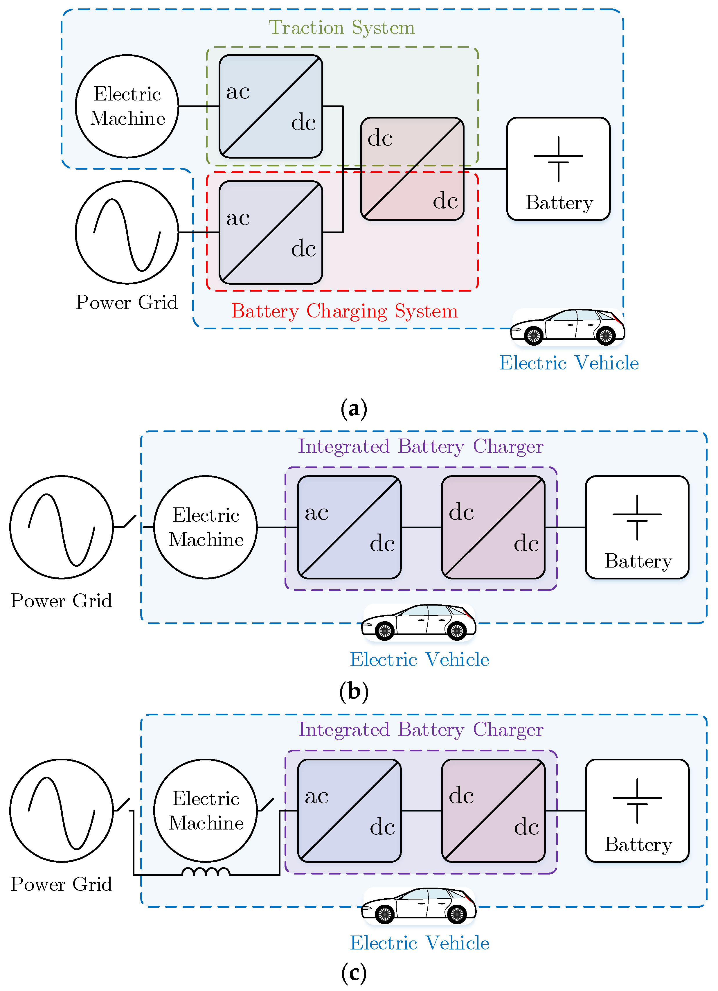
In terms of its constitution at the power electronics level, an EV contains a traction system, responsible for controlling one or more electric machines that guarantee the EV’s propulsion, and a battery charging system, responsible for charging the battery from an external source, e.g., the power grid [4]. Regarding the traction system, in order to energize the electric machine windings from a battery power source, as well as to perform the opposite process during a braking operation, a dc–ac converter is needed [5]. In addition, in order to adapt the dc voltage of the dc–ac converter, as well as to regulate the energy generated by the electric machine and returned to the battery during a braking operation, a bidirectional dc–dc converter is used [6]. Regarding the battery charging system, since power is supplied by an ac power grid (either single-phase or three-phase), an ac–dc converter is needed. Moreover, in the traction system, a dc–dc converter is needed for controlling the battery current and voltage during the charging operation, though this converter can be the same as the one previously referred to. This constitution can be seen in Figure 1a, representing the conventional power electronics structure of an EV. Regarding conductive charging, considering that the EV must be stationary in order to charge its battery, it can clearly be seen that the traction and battery charging systems are never used simultaneously. Furthermore, it can also be seen that the front-end converters dedicated to each system are very similar, interfacing an ac side (electric machine or power grid) to a common dc link. Taking these two factors into consideration, integrated battery chargers (IBCs) arose, which use the same power converter for traction and for battery charging. This approach can be seen in Figure 1b,c and is advantageous in the sense that it combines two functionalities in a single system, with the prospect of reducing the volume, weight and cost of the power electronics comprising the EV [7].
It can be seen that two types of IBCs are represented in the figure (Figure 1b,c). In Figure 1b, the electric machine windings are used as coupling filters with the power grid, while in Figure 1c external inductors are used. There are several ways of achieving an IBC, as can be seen by the different topologies published in the literature and patented [8]. Moreover, IBCs can present different specifications such as galvanic isolation, bidirectional operation with the power grid and the various possibilities for power grid interfacing (e.g., single-phase ac, three-phase ac or dc). However, they can also add complexity to the general system as additional inductors may be required to interface the converter with the power grid and/or contactors, to reconfigure the power converter. In [9] an analysis of IBCs is presented in terms of functionalities and implementation costs compared to dedicated systems that allow the same operation modes, with bidirectional operation also considered. Additionally, some proposed IBCs require access to the neutral point of the electric machine, which is not commonly necessary in conventional systems, and some IBCs even require access to all winding terminals in order to operate. Furthermore, there are IBCs that can be used with any electric machine type and others that are specifically designed for a given electric machine or for a number of given electric machines. In this context, this paper presents a review of the IBCs proposed in the literature and patented, as well as a comparison between them, both in terms of implementation requirements (e.g., the need for external inductors or contactors) and functionalities (e.g., galvanic isolation, bidirectional operation).
2. Integrated Battery Chargers
This section presents relevant IBCs that have been proposed in the literature. In order to better organize the presented topologies, this section is divided into five subsections, grouping the IBCs into: (1) classical topologies; (2) IBCs especially developed for switched reluctance machines (SRMs); (3) IBCs with galvanic isolation; (4) IBCs based on multiple traction converters; (5) IBCs based on multiphase machines. It should be noted that the section on classical IBCs contains some topologies that are more recent than those of some of the IBCs presented in other sections. This is because these topologies do not match any of the other criteria, i.e., for use with SRMs, with galvanic isolation or based on multiple traction converters or multiphase machines.
2.1. Classical Integrated Battery Chargers
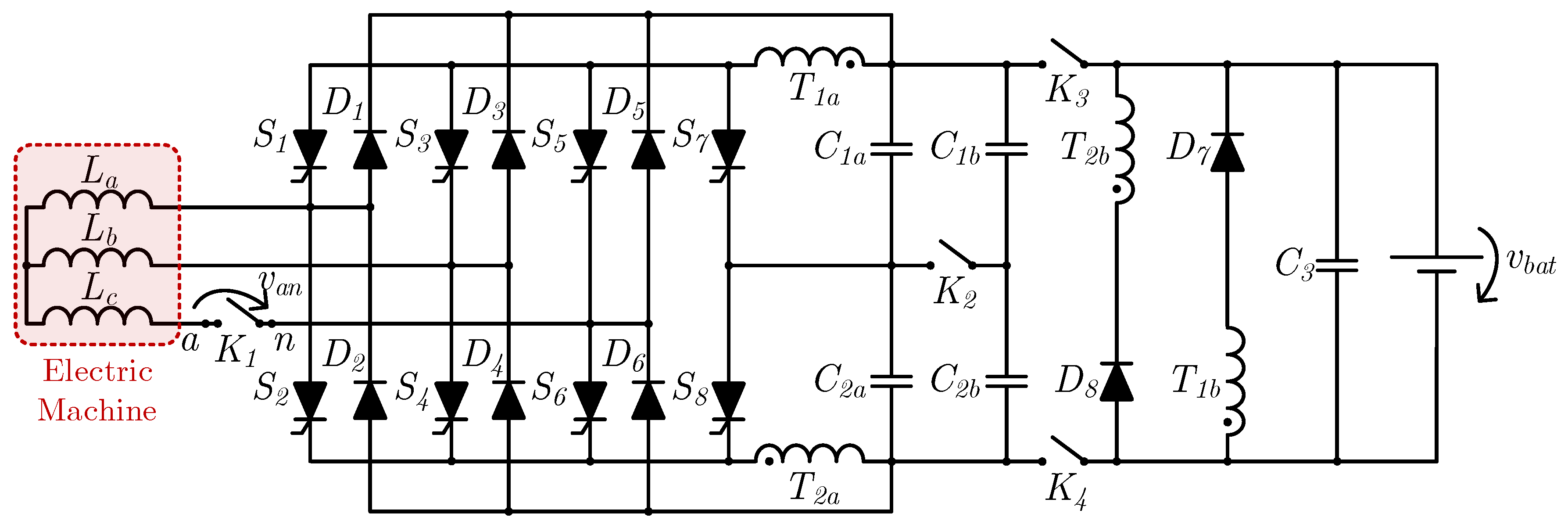
The first publication regarding EV IBCs dates back to 1983, a time when EVs were far from having the popularity they have nowadays. This publication consists of a United States Department of Energy report produced by NASA [10], and it was followed by a publication by the same author, D. Thimmesch, two years later [11]. The approach presented in both publications can be seen in Figure 2 and consists of a thyristor-based resonant three-phase dc–ac converter, sized for a mechanical peak power of 34 kW in the traction mode and a continuous power of 3.6 kW in the battery charging mode, which also uses a transformer comprising four windings (T1a, T1b, T2a, T2b). In traction mode, the system operates as a single converter, i.e., a resonant three-phase dc–ac converter (thyristors S1–S6), where the electric machine is of the three-phase type, while in battery charging mode the system operates with two separate converters (one ac–dc and the other dc–dc) connected to a single-phase ac power grid. The thyristor antiparallel diodes of the dc–ac converter (D1–D6) are employed as a diode full-bridge single-phase ac–dc converter, with the power grid connected in series in one of the converter phases (terminals a, n) and the stator windings of the electric machine (La, Lb, Lc) operating as coupling inductors with the power grid. The dc–dc converter, composed of thyristors S7 and S8 and diodes D7 and D8, operates as a resonant converter, similarly to the three-phase dc–ac converter used in traction mode. It should be noted that the battery charging operation is performed in an isolated way, using four contactors (K1–K4) that remain closed in traction mode and are opened in battery charging mode, isolating the batteries from the power grid.
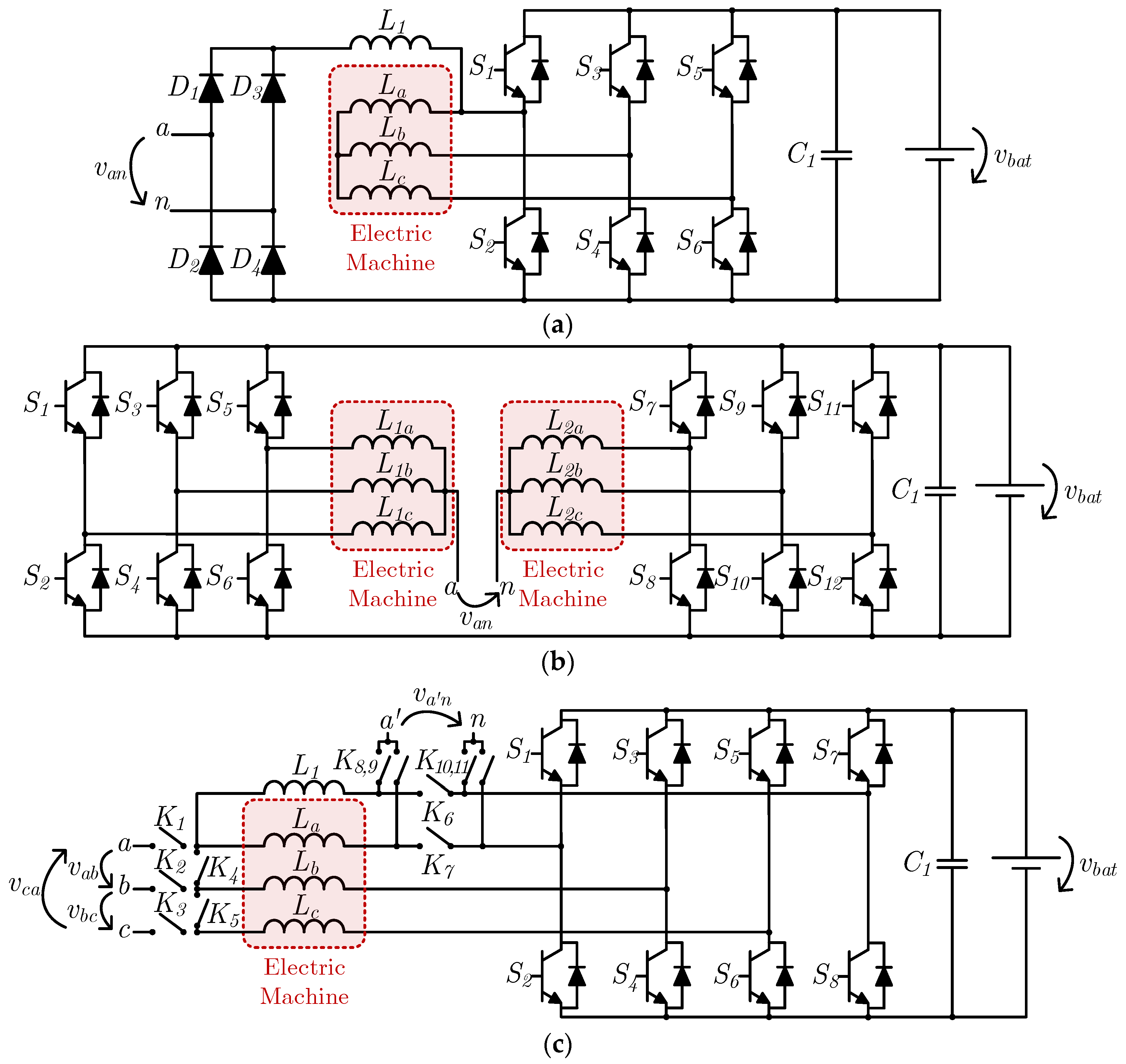
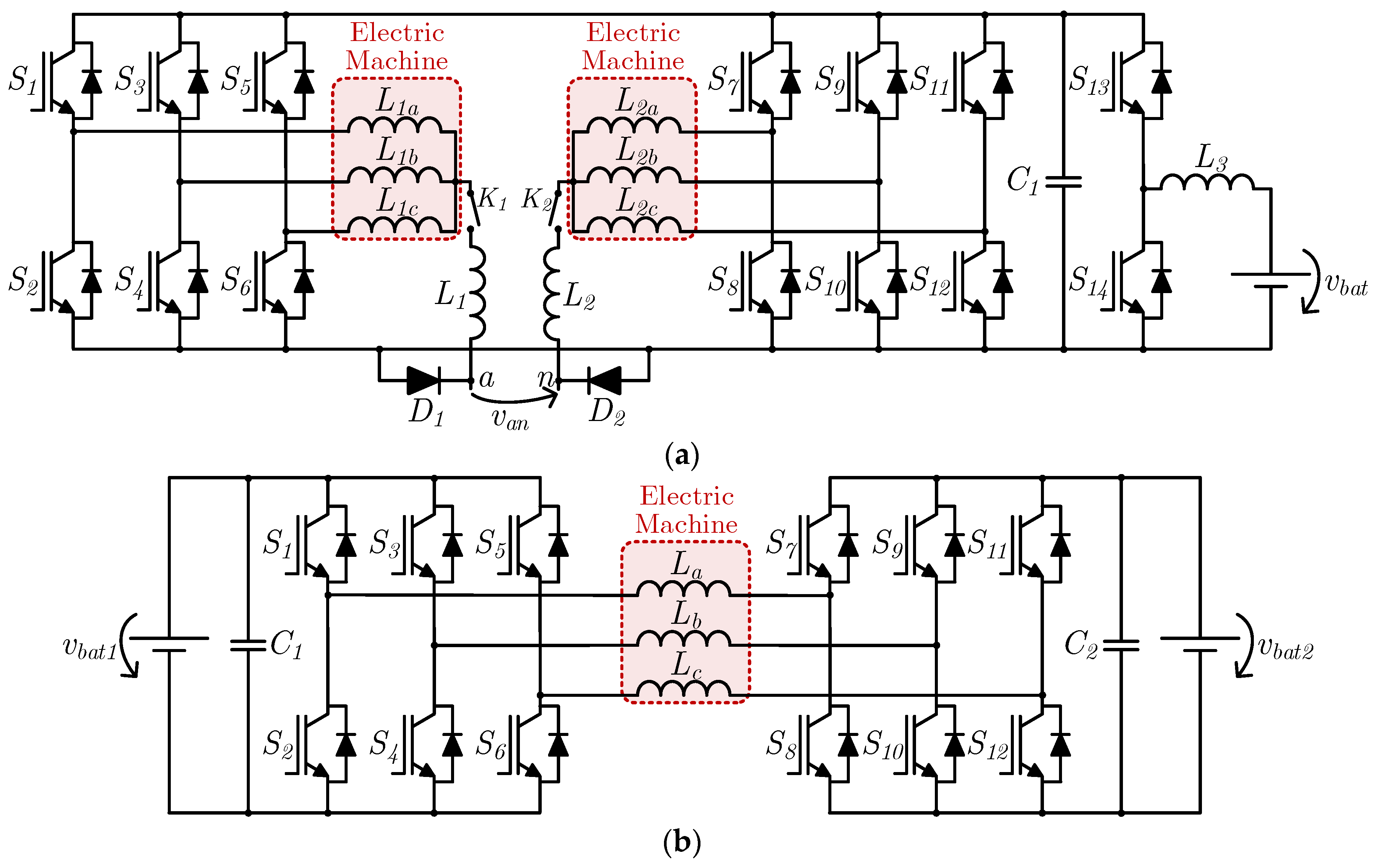
Several years later, in the early 1990s (1990 [12], 1992 [13] and 1994 [14]), three IBCs for EVs were patented by W. Ripple and A. Cocconi, as shown in Figure 3. The IBC patented in 1990 [12], shown in Figure 3a, consists of a bipolar-junction-transistor-based three-phase three-leg bidirectional ac–dc converter (S1–S6) and a diode full-bridge single-phase ac–dc converter (D1–D4). In traction mode, only the three-phase bidirectional ac–dc converter is used, and the electric machine is of the three-phase type. In battery charging mode, the diode full-bridge single-phase ac–dc converter is employed to interface the system with a single-phase ac power grid (terminals a, n), while the three-phase bidirectional ac–dc converter operates with only one leg, acting as a bidirectional buck–boost dc–dc converter. In battery charging mode, an additional inductor (L1) is used to reduce the battery current ripple, although the authors note that it is possible to use the electric machine windings, with the trade-off of a higher current ripple. The IBC patented in 1992 [13] concerns the application of two induction machines or, alternatively, one electric machine with two sets of windings, composed of two three-phase three-leg bidirectional ac–dc converters, as shown in Figure 3b. In traction mode, each of these converters controls one electric machine independently. In battery charging mode, the two terminals of a single-phase ac power grid are connected to the neutral point of each of the electric machine stator windings, such that the three-phase bidirectional converters operate in a three-phase interleaved configuration of a full-bridge single-phase bidirectional ac–dc converter. In contrast to the solution patented in 1990, this IBC does not use external inductors. The IBC patented in 1994 [14] (Figure 3c) consists of an adaptation of the previously patented solutions with the purpose of operating either in single-phase or three-phase ac power grids, using eleven contactors (K1–K11). Contactors K1–K3 are responsible for connecting the system to a three-phase ac power grid (terminals a, b, c), whereas K4 and K5 have the role of connecting the electric machine stator windings in a star configuration. Contactors K6–K11 are used to interface the system with a single-phase ac power grid (terminals a’, n). In this case, K6 and K7 remain open and K8–K11 are closed. As in the system patented in 1990 [12], an external inductor is used (L1). Unlike the topology patented in 1992 [13], which only needs access to the neutral points of the electric machine stator windings, this topology needs access to all six terminals in order to perform the connection to a three-phase ac power grid, with the stator windings behaving as coupling inductors. The three IBCs patented by W. Rippel and A. Cocconi have a common characteristic, namely, the requirement for the power grid peak voltage to be lower than the EV battery voltage, as is the case for any voltage source ac–dc converter with a single dc link, i.e., without being split.
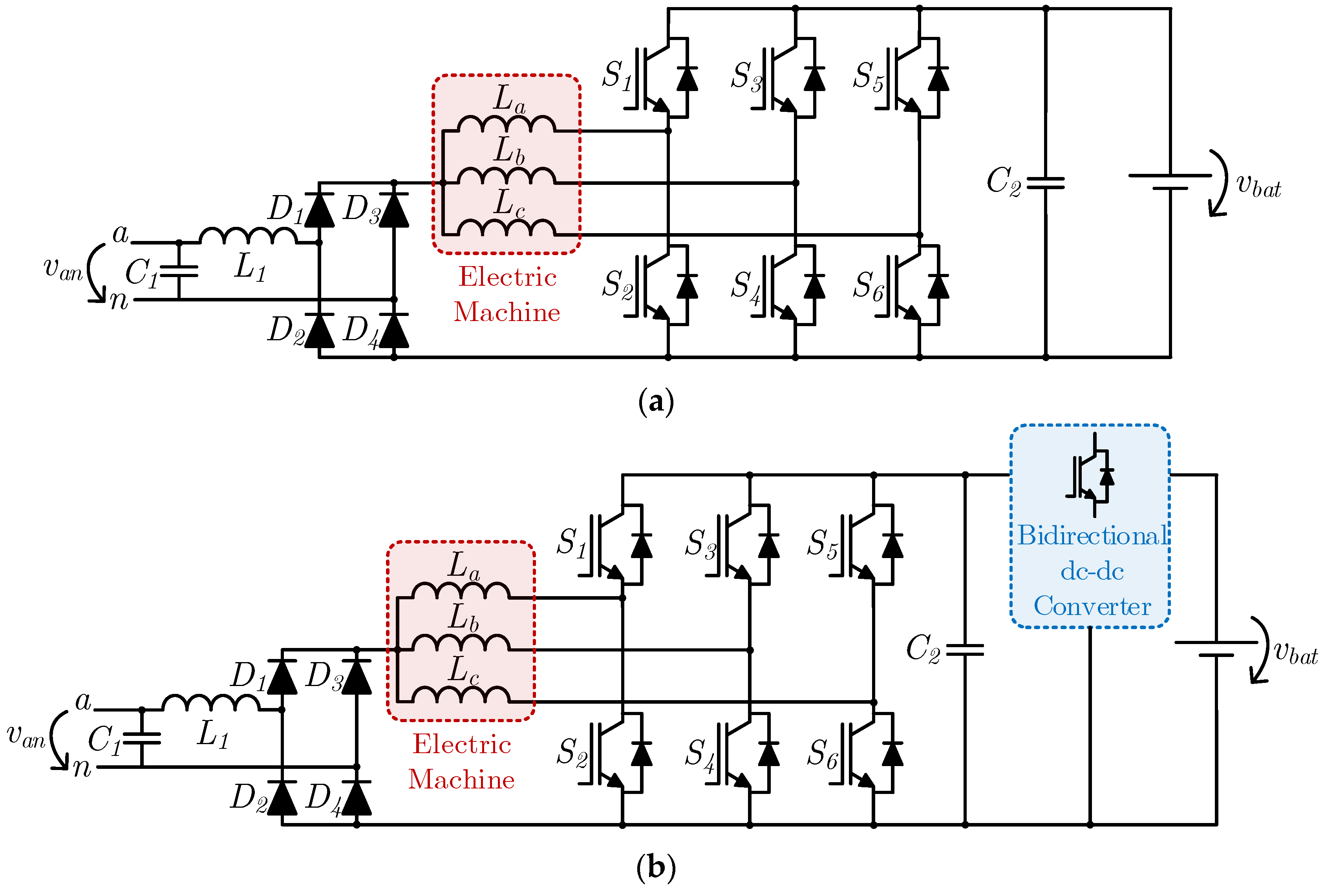
In 2001, L. Solero proposed an IBC for an electric scooter [15]. This system can be seen in Figure 4a. It is composed of a three-phase three-leg bidirectional ac–dc converter (insulated gate bipolar transistors (IGBTs) S1–S6) and a diode full-bridge single-phase ac–dc converter (diodes D1–D4). In traction mode, only the three-phase bidirectional ac–dc converter is used, controlling the electric machine, which is of the three-phase type. During battery charging mode, the diode full-bridge single-phase ac–dc converter is also used to interface the system with a single-phase ac power grid (terminals a, n), with the three-phase bidirectional ac–dc converter operating as a three-phase interleaved bidirectional buck–boost dc–dc converter. In this system, the stator windings behave as dc–dc converter inductors, and the neutral point is connected to the positive output terminal of the diode full-bridge single-phase ac–dc converter. In this case, the power grid peak voltage cannot be higher than the battery voltage due to the boost operation of the dc–dc converter from the power grid to the battery. In 2010, G. Pellegrino et al. proposed a similar system with an additional bidirectional dc–dc converter between the battery and the dc link of the three-phase bidirectional ac–dc converter, endowed with power factor correction (PFC) characteristics and allowing the battery charging operation from power grids with peak values that can be higher or lower than the battery voltage [16]. This topology can be seen in Figure 4b. It should be noted that the authors did not specify the dc–dc converter topology.
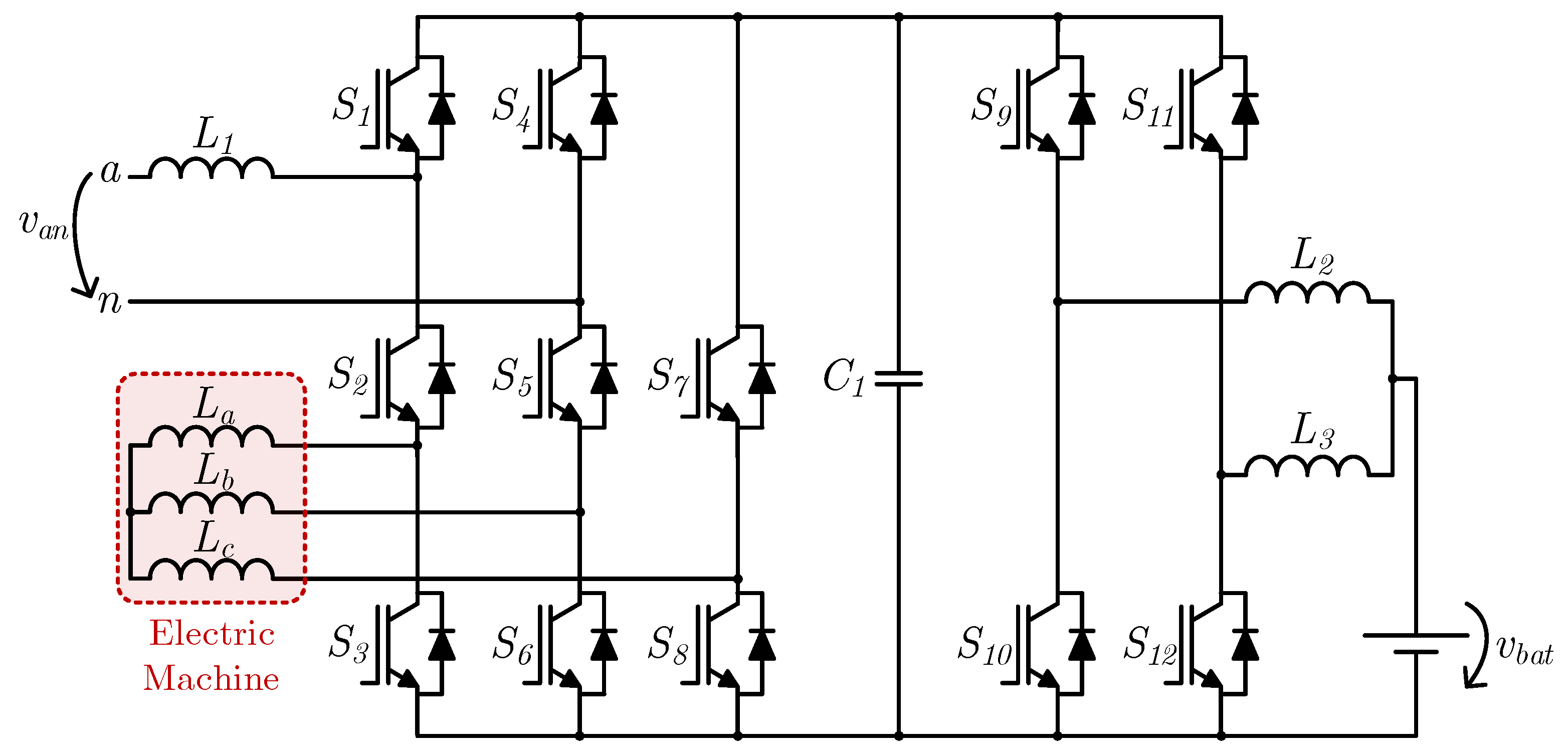
In 2013, O. Hegazy et al. proposed the IBC presented in Figure 5, which is based on an eight-switch three-phase ac–dc converter (S1–S8) and a two-phase interleaved buck–boost dc–dc converter (S9–S12), both bidirectional [17]. The ac–dc converter is composed of three legs, one of them with two switches (S7 and S8) and the other two with three switches (S1–S6). This approach allows a three-phase three-leg bidirectional ac–dc converter (S2, S3, S5, S6, S7, S8) to be simultaneously established with a full-bridge single-phase bidirectional ac–dc converter (S1, S2, S4, S5 or S1, S3, S4, S6), connected with a three-phase electric machine and a single-phase ac power grid (terminals a, n), respectively. Since the electric machine and the power grid are connected to different terminals of the ac–dc converter, no system reconfiguration is necessary in order to change the operation mode between machine drive and battery charging, and hence no relays or contactors are used. The only additional element is an inductor (L1), serving the purpose of interfacing the converter with the power grid. In order to guarantee the proper operation of the converter, IGBTs S1 and S4 are kept permanently closed in traction mode so that current flow in the three-phase three-leg bidirectional ac–dc converter (S2, S3, S5, S6, S7, S8) is allowed, while in battery charging mode IGBTs S2 and S5 (or S3 and S6) are kept permanently closed in order to allow current flow in the full-bridge single-phase bidirectional ac–dc converter (S1, S2, S4, S5 or S1, S3, S4, S6), while the third leg (S7 and S8) is kept permanently open.
2.2. Integrated Battery Chargers for Switched Reluctance Machines
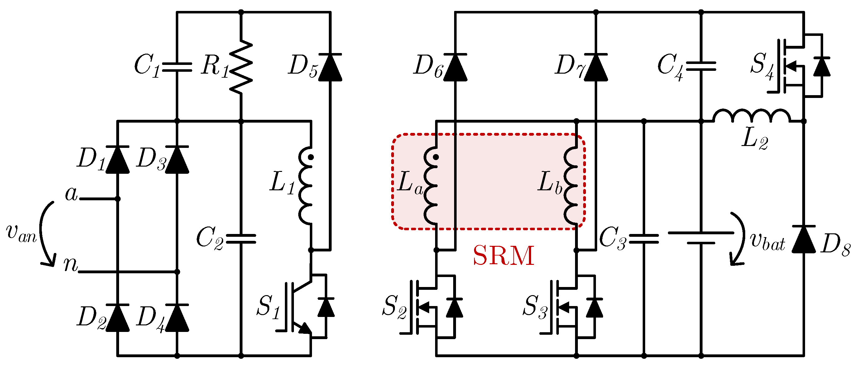
In 2000, C. Pollock and W. K. Thong proposed an IBC based on a two-phase SRM [18], as shown in Figure 6. As well as the converter that is typically used for traction systems in this type of machine (asymmetrical dc–ac converter), in this case of the two-phase type (comprising metal oxide semiconductor field effect transistors (MOSFETs) S2, S3 and diodes D6, D7), it also uses an energy recovery circuit (inductor L2, capacitor C4, MOSFET S4 and diode D8), an additional inductor (L1) coupled to one of the machine phases (in this case, La) with the respective diode (D5) and IGBT (S1) and a diode full-bridge single-phase ac–dc converter (D1–D4) for interfacing with a single-phase ac power grid (terminals a, n). The additional inductor L1 is only used in battery charging mode, making the system operate as a flyback isolated dc–dc converter. In addition, capacitor C1 and resistor R1 form an RC snubber and are also only used in battery charging mode.
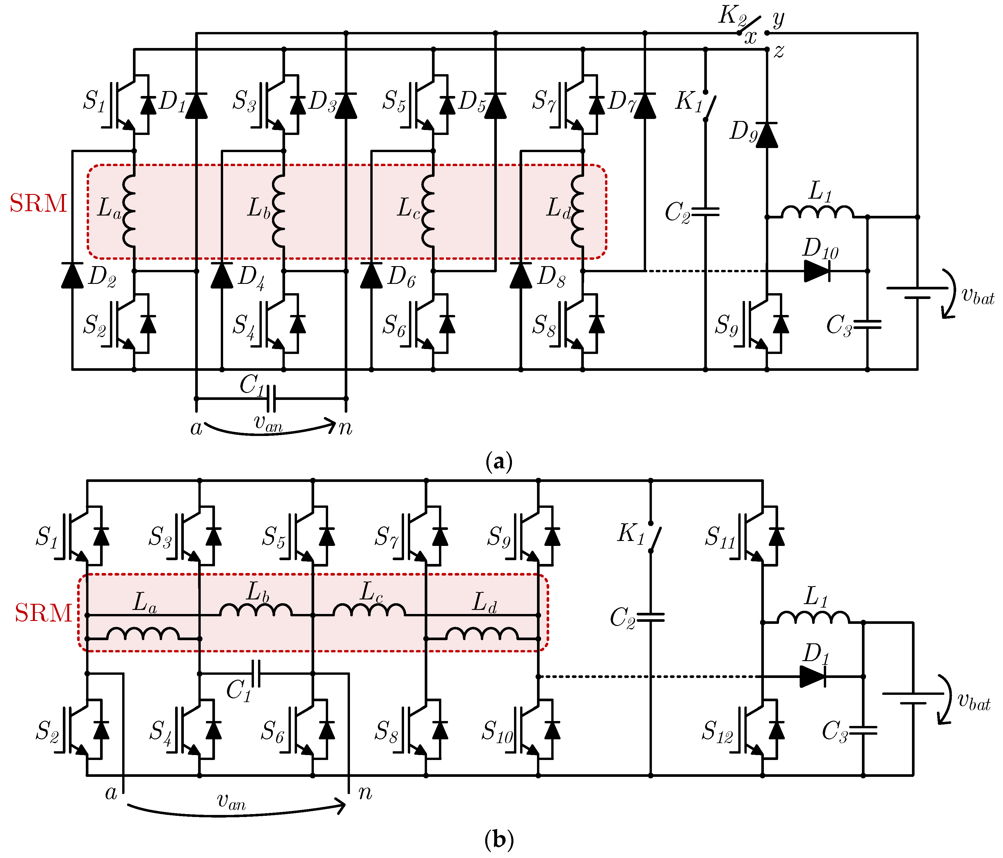
In 2009, H. C. Chang and C. M. Liaw proposed an IBC based on four-phase SRMs, as shown in Figure 7a, with the four-phase asymmetrical dc–ac converter (comprising IGBTs S1–S8 and diodes D1–D8) operating as a PFC converter in battery charging mode [19]. In this system, in traction mode, the unidirectional boost dc–dc converter formed by IGBT S9, diode D9 and inductor L1 is used to step up the voltage from the battery to the dc link of the asymmetric dc–ac converter. On the other hand, in battery charging mode, the unidirectional boost dc–dc converter is not used, and two of the stator windings are used as input passive filters (in this case La, Lb) of a diode full-bridge single-phase ac–dc converter (D1–D4) used for interfacing with a single-phase ac power grid (terminals a, n). One of the remaining stator windings (in this case Ld) is used as an inductor for a unidirectional buck–boost dc–dc converter, which is composed of two IGBTs (S7, S8) and a diode (D8) that belong to the traction converter. In battery charging mode, an extra diode (D10) is also used to avoid short-circuiting the battery when S8 is turned on. This diode exists on board the EV but its connection is performed through an off-board shunt; hence, it is represented with a dashed line. Moreover, two contactors are used, one with two positions (K1) and the other with three (K2). Contactor K1 remains closed in traction mode and is opened in battery charging mode, connecting capacitor C2 in parallel with the converter legs in traction mode. Contactor K2 allows point x to be connected to one of two points, depending on the operation mode, namely, to point y in traction mode and point z in battery charging mode. In 2011, the same authors proposed modifications to this system, allowing the battery to be charged through a buck–boost or a buck configuration, with the latter being advantageous in the sense that it inserts an inductor in series with the battery, reducing its current ripple [20]. This topology is shown in Figure 7b, where it can be seen that the asymmetric dc–ac converter has a modified structure, using five IGBT legs (S1–S10) instead of four IGBT pairs and four diode pairs, reducing the semiconductor count from 16 to 10. In contrast to the system previously proposed by the authors, only one contactor (K1) is used, which is responsible for connecting the capacitor C2 in parallel with the converter legs in traction mode. Like diode D10 presented in the previous topology, diode D1 serves the purpose of avoiding short-circuiting the battery during its charging process when IGBT S10 is conducting.
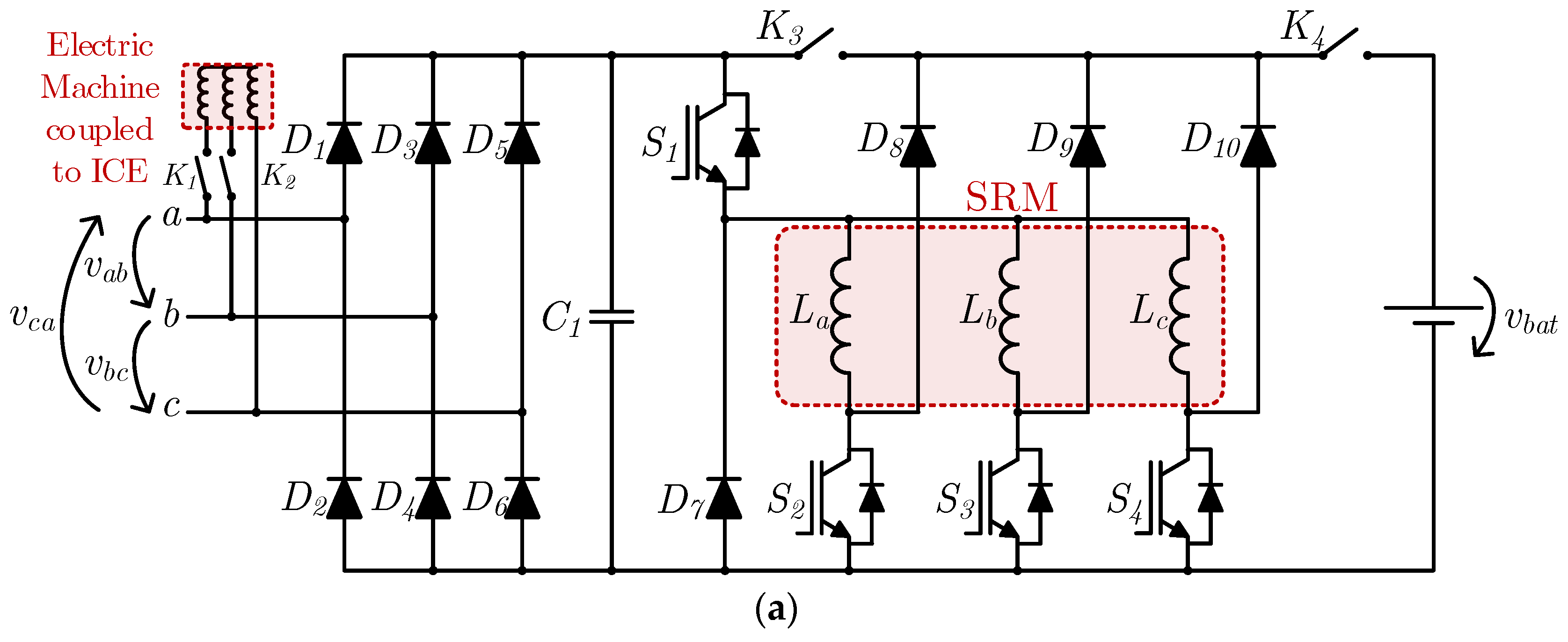
In 2014, Y. Hu et al. proposed an IBC for plug-in hybrid vehicles based on three-phase SRMs [21]. This topology is shown in Figure 8a. It is composed of an asymmetric dc–ac converter based on n + 1 switches (S1–S4) and n + 1 diodes (D7–D10), where n is the number of machine phases. This converter is also known as a Miller converter and is an alternative to the more commonly used version for SRM drives, in which 2n switches and 2n diodes are used. By adding a diode full-bridge three-phase ac–dc converter (D1–D6) and two contactors (K3 and K4), the asymmetric converter can operate as a dc–ac converter for driving the machine or as a buck dc–dc converter, where the machine stator windings behave as output inductors and the battery current is divided between the three windings. The input of the diode full-bridge three-phase ac–dc converter (terminals a, b, c) can be used for interfacing either with a power grid (single-phase ac, three-phase ac or dc) or a generator mechanically coupled with the internal combustion engine (ICE) of the vehicle via contactors K1 and K2. These contactors are closed whenever the ICE-coupled generator is used, as is the case for generator-only driving and hybrid driving in traction mode. Contactor K3 is used in traction mode, either in generator-only driving, battery-only driving or hybrid driving, and should be kept open in battery charging mode in order to establish a buck dc–dc converter. Contactor K4 is closed whenever the battery is used, either in traction mode (in battery-only driving and hybrid driving modes) and in battery charging mode.
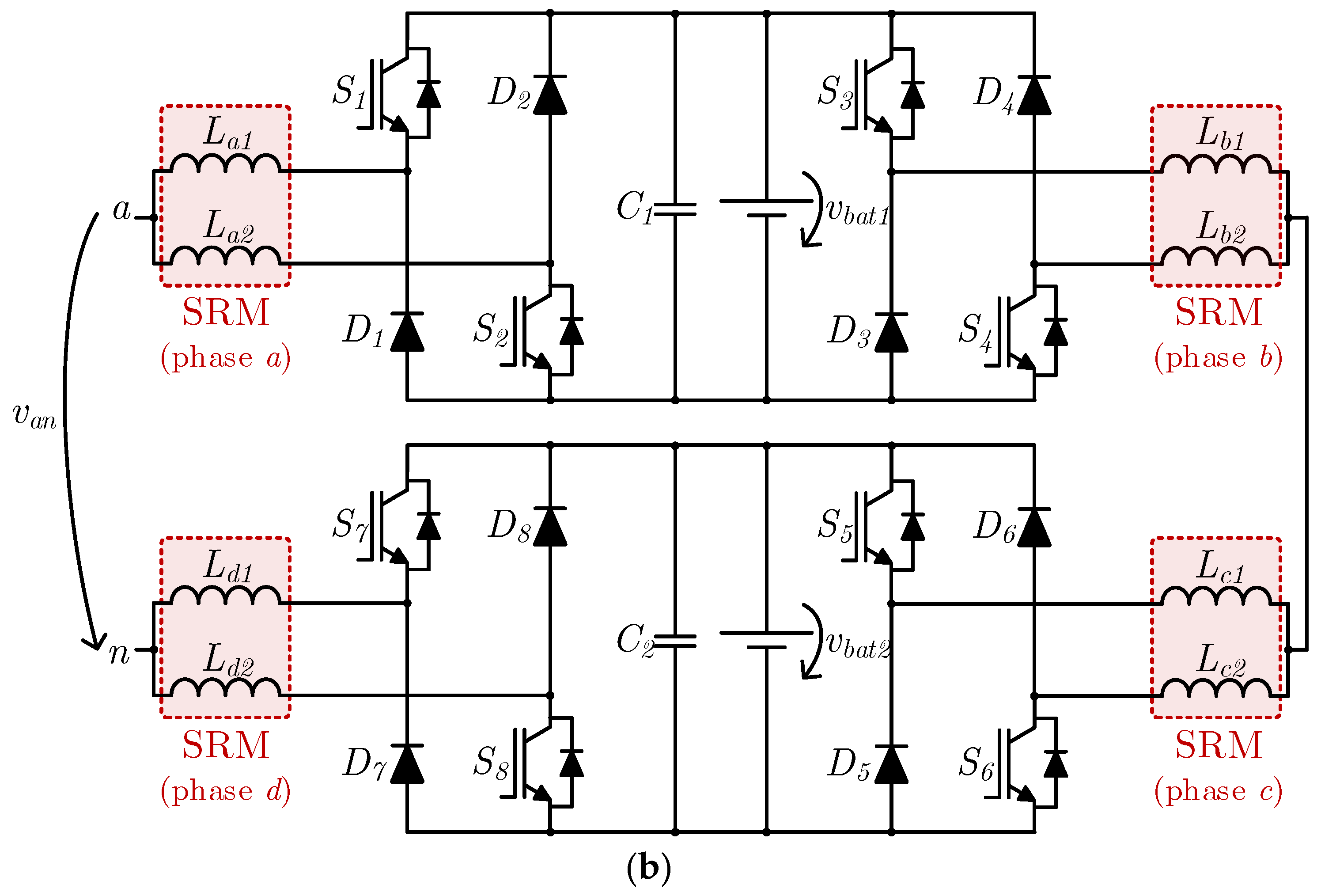
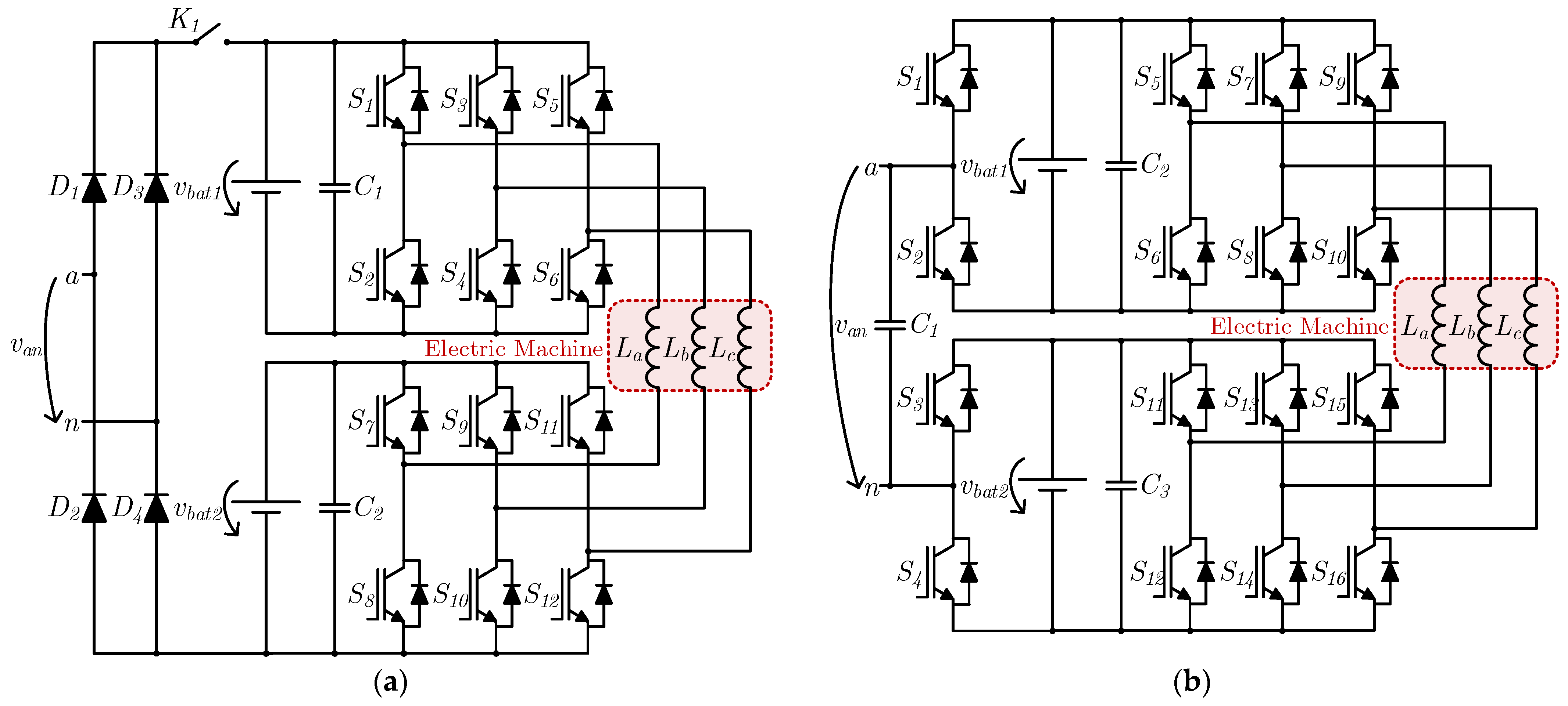
In 2015, the same authors proposed the IBC presented in Figure 8b, for application in EVs or plug-in hybrid vehicles, based on four-phase SRMs with two sets of stator windings [22]. Two asymmetrical converters with 2n switches and 2n diodes are employed, with each one applied to two machine phases, and a battery set is connected to the dc link of each converter. Hence, each of these converters can operate independently in traction mode. Regarding the battery charging mode, this topology allows operation with dc and single-phase ac power grids, where both converters are connected to each other in two of the phases (b, c) and the other two (a, d) operate as connection terminals to the power grid (terminals a, n). In the case of a dc power grid, the converters operate as two cascade-connected split-pi unidirectional buck–boost dc–dc converters, whereas in the case of a single-phase ac power grid the converters operate as a five-level cascaded h-bridge ac–dc converter (despite having more semiconductors than necessary). In both cases, due to the boost operation of the converter from the power grid to each set of batteries, the power grid peak voltage should be lower than the battery voltage for proper operation in battery charging mode.
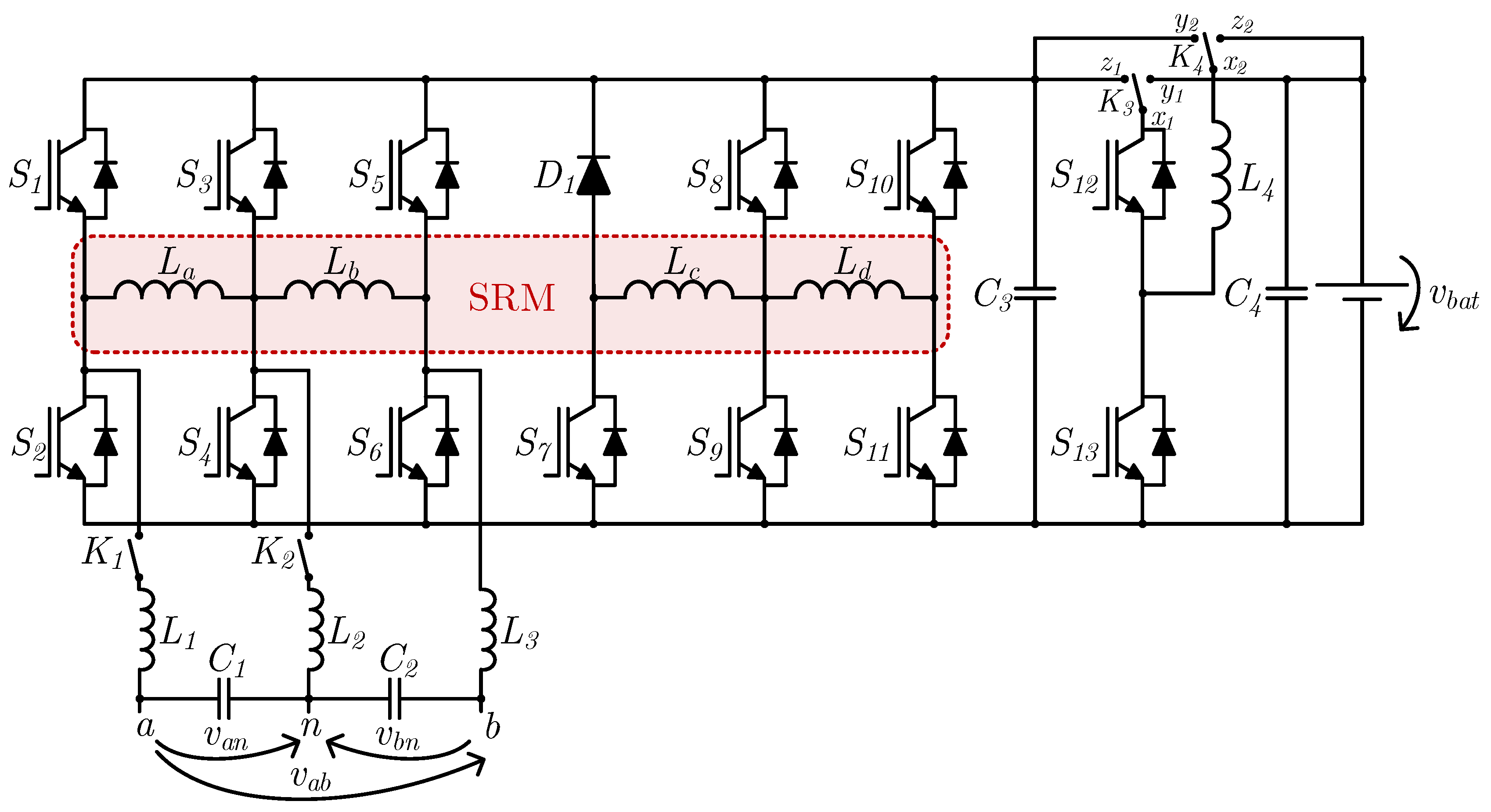
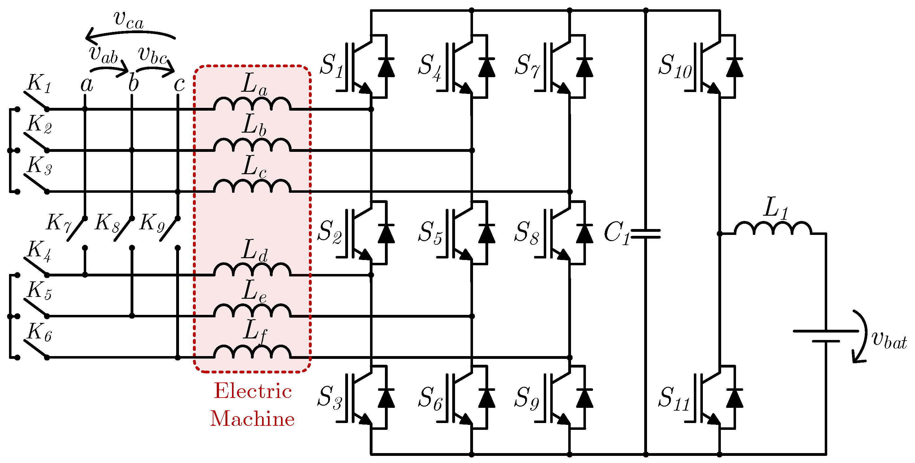
K.W. Hu et al. proposed, also in 2015, an IBC with additional operation modes, namely, vehicle-to-grid (V2G) and vehicle-to-home (V2H) [23] modes. This topology can be seen in Figure 9 and is based on a four-phase SRM and an asymmetric dc–ac converter similar to the one presented in 2011 [20] with five switch legs (S1–S6 and S8–S11) but also with an extra leg comprising a diode (D1) and a switch (S7). Moreover, a bidirectional buck–boost dc–dc converter is used (IGBTs S12, S13 and inductor L4), which may be reconfigured to operate in buck or boost mode in each direction, depending on the states of the three-position switches K3 and K4. In traction mode, these switches are configured in order to connect points x1, x2 to points y1, y2, respectively, linking the higher voltage side (leg formed by S12, S13) to the battery and linking the lower voltage side (inductor L4) to the asymmetrical dc–ac converter dc link. In this regard, when the intention is to drive the machine, the bidirectional buck–boost dc–dc converter operates in buck mode during regular traction mode and in boost mode during regenerative braking, and hence the battery voltage must be higher than the dc link voltage of the asymmetrical dc–ac converter. On the other hand, in battery charging mode, the switches K3, K4 are configured in order to connect points x1, x2 to points z1, z2, respectively, linking the higher voltage side (leg formed by S12, S13) to the asymmetric dc–ac converter dc link and linking the lower voltage side (inductor L4) to the battery. In battery charging mode, the bidirectional buck–boost dc–dc converter operates in buck mode during the conventional battery charging operation, i.e., in grid-to-vehicle (G2V) mode, and in boost mode during V2G or V2H operation modes, and therefore the dc link voltage must be higher than the battery voltage. The battery charging operation can be performed via a single-phase or a two-phase (using only one phase-to-phase voltage) ac power grid, where a single-phase three-wire bidirectional ac–dc converter is used, which is implicit in the asymmetric dc–ac converter (S1–S6). In order to connect the system to the power grid, two contactors (K1, K2), three inductors (L1, L2, L3) and two capacitors (C1, C2) are used, where the three-wire interface (terminals a, n, b) allows two phase-to-neutral voltages (van, vbn) and a phase-to-phase voltage (vab) to be obtained.
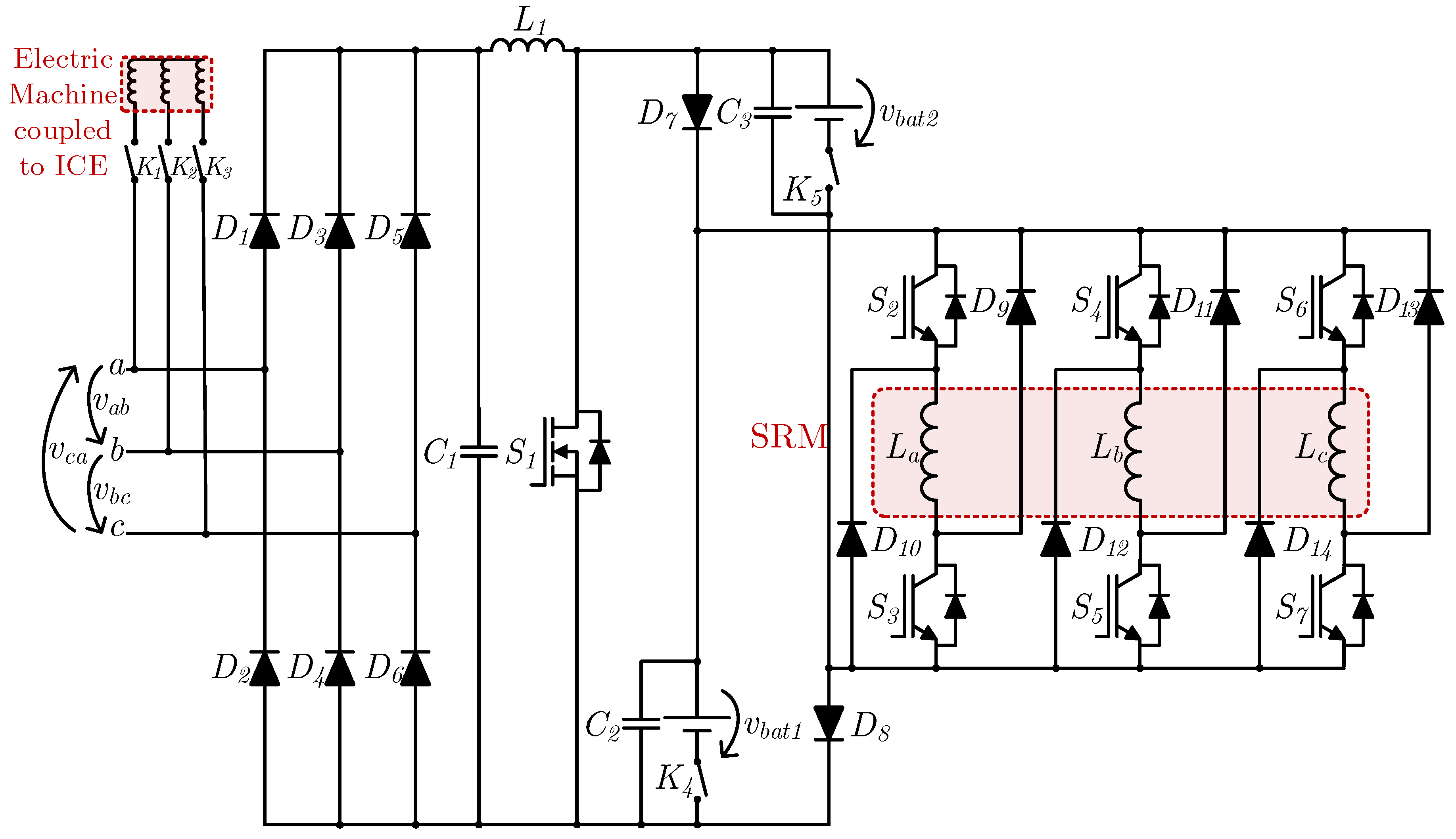
In 2018, M. Ma et al. proposed an IBC for plug-in hybrid vehicles based on SRMs, as shown in Figure 10 [24]. This topology consists of the asymmetric dc–ac converter typically used in SRMs (IGBTs S2–S7 and diodes D9–D14) with the addition of a boost PFC stage (diodes D1–D6, capacitor C1, inductor L1 and MOSFET S1) to connect to a three-phase ac power grid (terminals a, b, c) or to a generator mechanically coupled to the ICE of the vehicle, using contactors K1–K3. Both stages are linked through a bridge formed by the diodes D7 and D8 and two battery sets (vbat1, vbat2), each with the respective capacitor connected in parallel (C2, C3) and a contactor connected in series (K4, K5), behaving as an energy recovery circuit. The contactors present in this topology have the purpose of enabling or preventing the use of the power provided by the generator (K1–K3) or by the batteries (K4, K5), making it possible to use the former, the latter or a combination of both, as required in a hybrid vehicle.
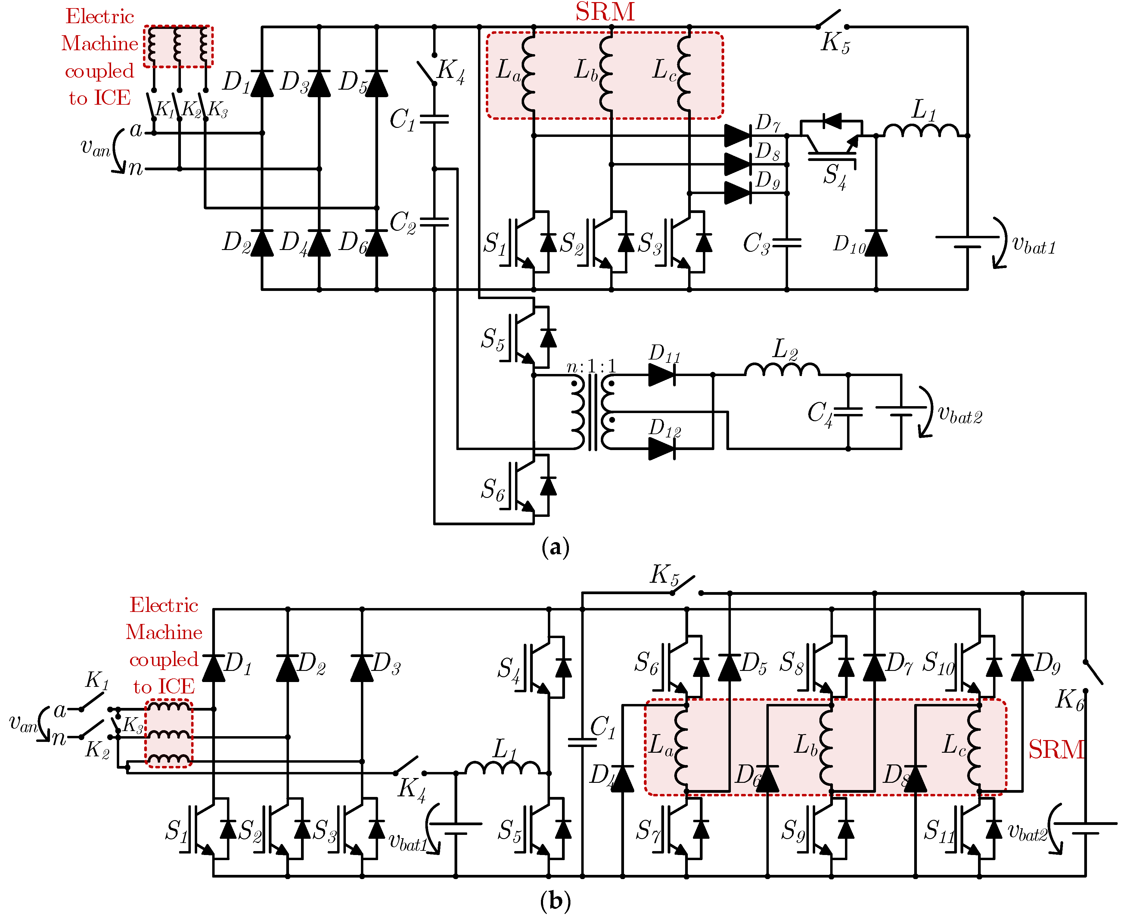
In 2020, H. Cheng et al. proposed the IBC for plug-in hybrid vehicles based on SRMs presented in Figure 11a [25]. Like the previously presented IBC, this proposal comprises a connection to an electric machine coupled to the ICE of the vehicle or to a power grid, in this case not three-phase ac but single-phase ac. As well as allowing the connection to the traction battery, this topology also allows the connection to the auxiliary battery. The front-end converter employed in this case is a diode full-bridge ac–dc converter (diodes D1–D6), while the converter for driving the machine is formed by IGBTs S1–S4, diodes D7–D10, capacitor C3 and inductor L1. Like the IBC for SRMs first presented in this section, this IBC uses an energy recovery circuit, which is based on IGBT S4, diode D10, capacitor C3 and inductor L1. The converter used to charge the auxiliary battery is a unidirectional isolated half-bridge dc–dc converter, which is formed by IGBTs S5 and S6, a high frequency transformer to step down the voltage, diodes D11 and D12, inductor L2 and capacitor C4. The series connection of capacitors C1 and C2 establishes a midpoint available to this converter. In terms of operation modes, this IBC allows charging the traction battery from the power grid, charging the auxiliary battery from the electric machine coupled to the ICE or charging the auxiliary battery from the traction battery. In order to change the operation mode, five contactors are used (K1–K5), where the first three (K1–K3) have the purpose of disconnecting the electric machine coupled to the ICE (when the power grid is connected), K4 is used when the vehicle is driving in hybrid mode, using the electric machine coupled to the ICE and K5 is used when the traction battery is used in traction mode.
In the same year, the same authors proposed a similar system in which the electric machine coupled to the ICE is also an SRM (Figure 11b) [26]. In this case, the converter used to drive the ICE-coupled machine is the same as the converter used to drive the main machine in the previous proposal, with the main difference that the windings can be reconfigured to be connected to a common neutral or isolated via contactor K3. Similarly, interfacing with a single-phase power grid is feasible, and the topology also allows charging of both the traction and auxiliary batteries. As well as the converter for driving the ICE-coupled electric machine (IGBTs S1–S3 and diodes D1–D3), this system uses a typical asymmetrical dc–ac converter to drive the main SRM (IGBTs S6–S11 and diodes D4–D9) and a bidirectional buck–boost dc–dc converter (IGBTs S4 and S5 and inductor L1) interfacing with the traction battery (vbat1). The system uses six contactors, where K1 and K2 are used to interface the converter with a single-phase ac power grid, K3 is used to create the neutral point of the ICE-coupled SRM as noted, K4 is used to charge the traction battery from the ICE-coupled SRM, K5 is used to drive the main SRM and K6 is used to charge the auxiliary battery (vbat2). On this basis, there are five possible operation modes during traction operation, namely: (1) battery-only driving, where the vehicle behaves as an EV; (2) ICE-coupled SRM-only driving, where the power generated by the SRM is sufficient to drive the main SRM; (3) ICE-coupled SRM and battery hybrid driving, where the power to the main SRM comes from the two sources mentioned; (4) ICE-coupled SRM driving and battery charging, where the power generated by the SRM is more than the power required to drive the main SRM, and thus the surplus power is used to charge the traction battery; (5) regenerative braking, where the main SRM acts as a generator and charges the traction battery. Furthermore, during the battery charging operation (when the vehicle is stationary) there are three possible operation modes: (1) traction battery charged from the power grid; (2) auxiliary battery charged from the power grid; (3) auxiliary battery charged from the traction battery.
2.3. Integrated Battery Chargers with Galvanic Isolation
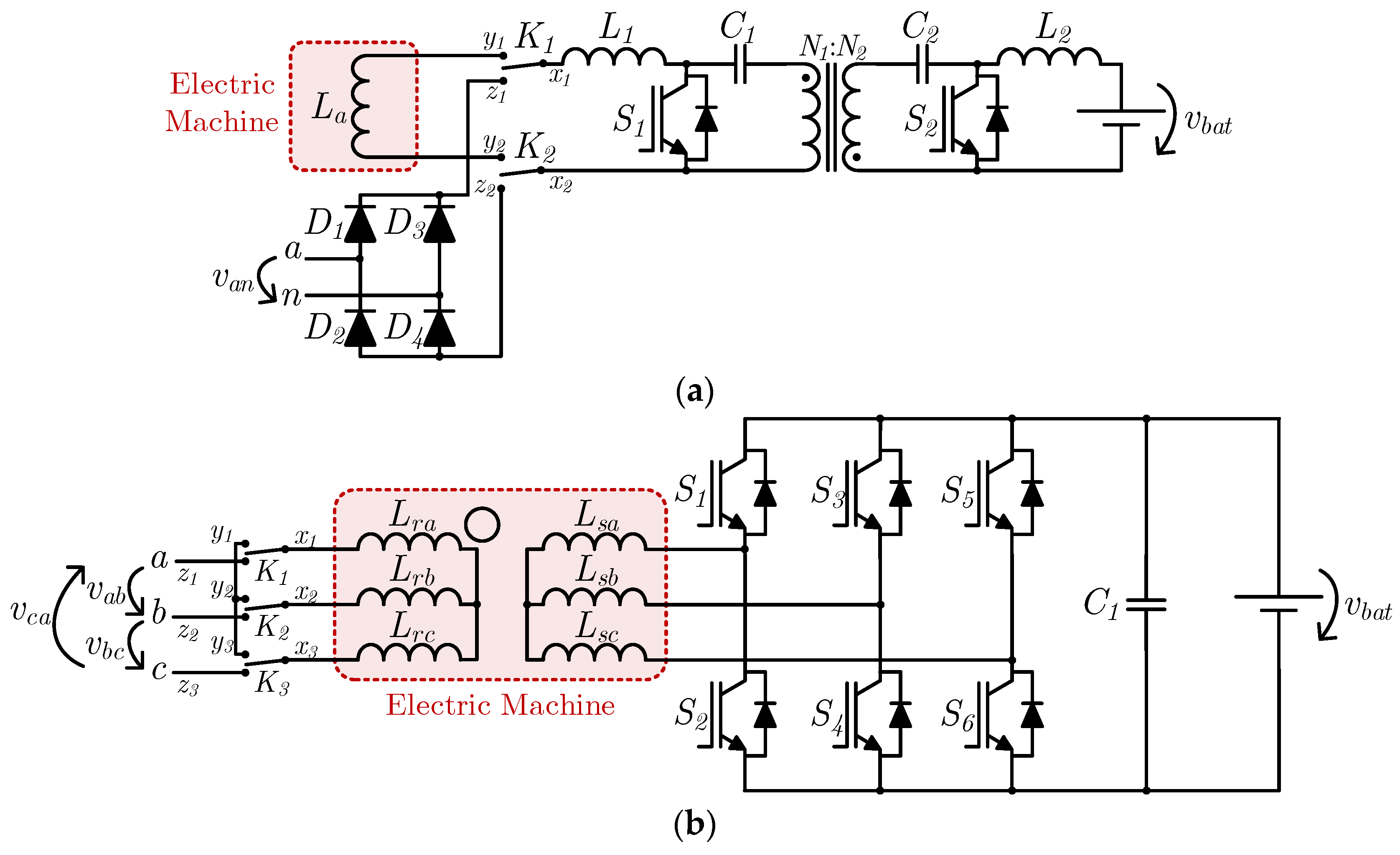
In 2005, F. Lacressonniere and B. Cassoret proposed two IBCs with galvanic isolation for industrial EVs [27]. One of these systems aims at application in pallet trucks based on 1.5 kW dc machines (Figure 12a), where galvanic isolation is achieved through a bidirectional isolated Cuk dc–dc converter (inductors L1, L2, capacitors C1, C2, IGBTs S1, S2 and a transformer with turns ratio N1:N2). As a dc traction drive system, this converter is responsible for both the battery interface and the machine drive. As well as this converter, it also uses a diode full-bridge single-phase ac–dc converter (D1–D4) to interface the system with a single-phase ac power grid (terminals a, n) in battery charging mode, with the dc–dc converter operating as a PFC converter. In order to switch between operation modes, two three-position switches are used (K1, K2) to change the dc–dc converter connections (points x1, x2), connecting it either to the machine (points y1, y2) or to the dc link of the ac–dc converter (points z1, z2). On the other hand, the second IBC proposed by the authors aims at application in forklifts based on a 6 kW wound rotor induction machine (Figure 12b). In this case, galvanic isolation is ensured by the machine itself in battery charging mode, where a three-phase ac power grid (terminals a, b, c) is connected to the rotor windings (Lra, Lrb, Lrc), whose nominal voltage is 400 V, and a three-phase three-leg bidirectional ac–dc converter (S1–S6) is connected to the stator windings (Lsa, Lsb, Lsc), whose nominal voltage is 48 V. In order to switch between operation modes, three three-position contactors are used (K1, K2, K3), which short-circuit the rotor windings in traction mode (points y1, y2, y3), connecting them in a star configuration and leaving them independent in battery charging mode in order to connect to the power grid (points z1, z2, z3). In this way, the bidirectional ac–dc converter operates as a dc–ac converter in traction mode and as an ac–dc converter in battery charging mode, controlling the currents absorbed from the power grid and the charging process of the battery. It should be noted that no additional inductors are used, with the machine stator windings behaving as inductive filters. It is also important to note that, in battery charging mode, the rotor must be mechanically braked since the machine is asynchronous and torque is created whenever its windings are energized.
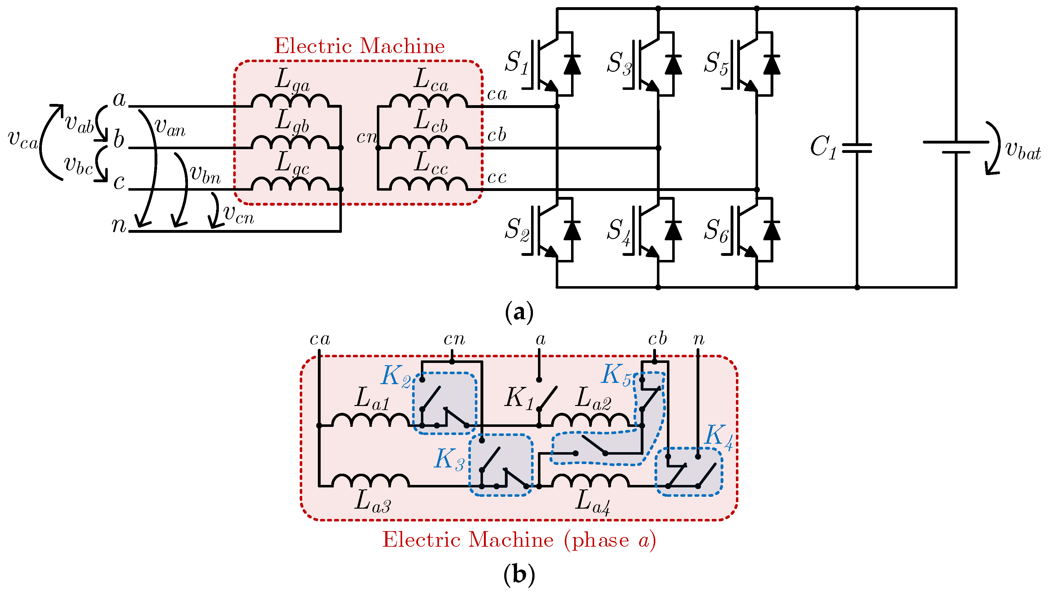
In 2011, S. Haghbin et al. proposed an IBC with galvanic isolation based on stator winding reconfiguration of a three-phase electric machine [28]. The machine referred to is composed of four stator windings per phase, with all 24 winding terminals being externally accessible. As can be seen in Figure 13a, the only converter present in this topology is a three-phase three-leg bidirectional ac–dc converter (S1–S6), which is responsible for interfacing the battery and the machine. However, 12 relays and a three-phase contactor are used in order to reconfigure the stator windings. In Figure 13b, it is possible to see in detail the stator windings referring to phase a (La1, La2, La3, La4), as well as one of the phases of the three-phase contactor (K1) and the four associated relays (K2–K5), with each relay being composed of a normally opened contact and a normally closed one. In traction mode, the windings of each phase are connected in a series–parallel arrangement (e.g., in phase a, La1 and La2 are connected in series, as well as La3 and La4, with the two groups being connected in parallel with each other), and the machine is connected using a delta configuration. This configuration is respective to the normally closed state of the four relays. In the case of phase a, its windings are connected to phases a and b of the converter (terminals ca, cb, respectively). In battery charging mode, the windings of each phase are connected and isolated in pairs, where two of them are connected to the converter and the other two are connected to the respective phase of a three-phase ac power grid (terminals a, b, c), while the neutral point is connected to the power grid neutral (terminal n). For instance, in phase a, La1 and La3 are connected in parallel, with one of the resulting terminals connected to phase a of the converter (terminal ca) and the other to a point common to the other phases (terminal cn), i.e., the winding Lca is formed by the parallel connection of La1 and La3. On the other hand, La2 and La4 are connected in series, where one of the resulting terminals is connected to phase a of the power grid (terminal a) through contactor K1 and the other is connected to a point common to the other phases, which in turn is connected to the power grid neutral (terminal n), i.e., the winding Lga is formed by the series connection of La2 and La4. Accordingly, it can be seen that the machine operates as a transformer, since there is no galvanic connection between the two sets of stator windings for the same phase. In 2013, the same authors analyzed this approach from a practical point of view [29], also giving attention to the electric machine design and to the phase shift used between both sets of stator windings [30].
In 2020, Z. Wang et al. proposed the galvanically isolated IBC presented in Figure 14 [31]. This topology is composed of a four-leg three-phase ac–dc converter (S1–S8), an active snubber in the dc link (S9 and C2) and a dual active bridge dc–dc converter (S10–S17), where the galvanic isolation is ensured. In traction mode, the ac–dc converter only operates with three legs during normal conditions; the fourth leg (S7 and S8) is only used in fault-tolerant operation, in which contactor K1 is kept closed. In battery charging mode, the neutral point of the machine windings is used to connect to the phase terminal of a single-phase ac power grid, where the midpoint of the fourth leg is connected to neutral. This IBC allows bidirectional operation with the power grid and has a small capacitance value for the dc link capacitor C2 due to the active snubber. In addition, owing to the voltage conversion ratio of the dual active bridge dc–dc converter, a low-voltage battery can be used.
2.4. Integrated Battery Chargers Based on Multiple Traction Converters
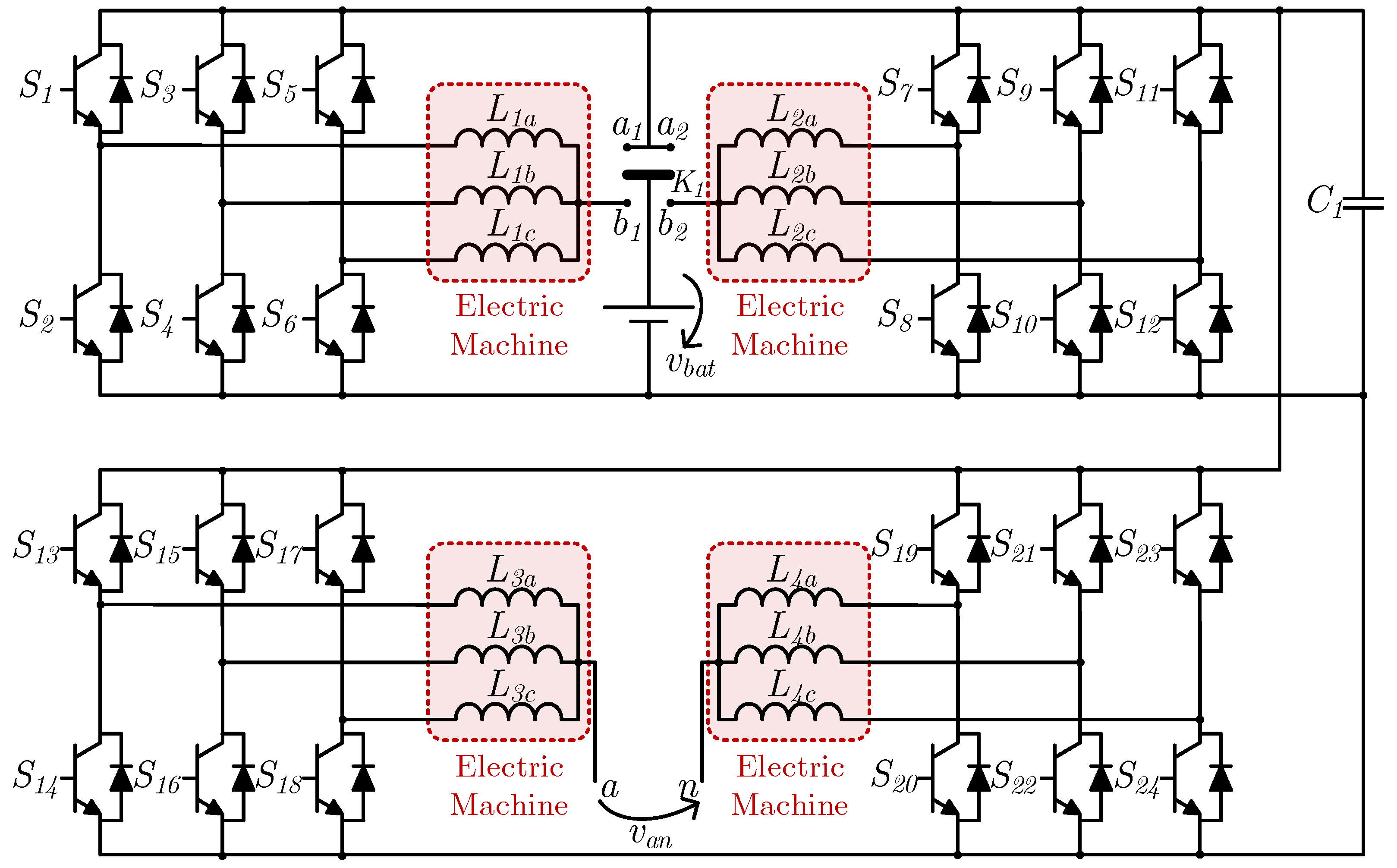
In 1995, S. K. Sul and S. J. Lee proposed an IBC for an all-wheel-drive EV, containing four electric machines and four three-phase three-leg bidirectional ac–dc converters, as well as a switch with two terminal pairs used for selecting the connection point of the positive battery terminal [32]. This topology can be seen in Figure 15. In traction mode, each ac–dc converter controls each electric machine independently, endowing the EV with all-wheel drive, with K1 connecting the batteries to the dc link terminals of all converters (terminals a1, a2). In battery charging mode, each group formed by two ac–dc converters and two electric machines is used to employ two bidirectional interleaved converters, namely, a buck–boost dc–dc converter (S1–S12) and a full-bridge single-phase ac–dc converter (S13–S24) for interfacing with a single-phase ac power grid (terminals a, n). In this case, the neutral points of two of the electric machines are used for interfacing with a single-phase ac power grid, while the neutral points of the other two electric machines are connected to the positive battery terminal by means of the switch (terminals b1, b2). The utilization of two converters in battery charging mode allows the power grid peak voltage to be higher or lower than the battery voltage, provided it is lower than the dc link voltage due to the boost operation of the dc–dc converter from the battery to the dc link.
In 2015, D. G. Woo et al. proposed an IBC based on two electric machines for interfacing with single-phase ac power grids, as shown in Figure 16a [33]. This topology is composed of two three-phase three-leg bidirectional ac–dc converters (S1–S6 and S7–S12), with each ac side connected to the stator windings of each electric machine, and the dc link is shared between these converters and connected to a bidirectional buck–boost dc–dc converter (IGBTs S13, S14 and inductor L3), which in turn interfaces with the battery. In battery charging mode, the three-phase ac–dc converters operate as boost dc–dc converters, with each converter operating in a power grid half cycle, and the stator windings of each machine are used as inductors in each converter. Furthermore, between the neutral point of each electric machine and the connection terminals to the power grid, two contactors (K1 and K2), two inductors (L1 and L2) and two diodes (D1 and D2) are used, where the diodes are used to reduce the common-mode noise, connecting the system ground to neutral (terminal n) during the power grid positive half cycle or to the phase (terminal a) during the power grid negative half cycle. The inductors are applied in order to compensate for the small common-mode inductance values of the stator windings.
In the same year, J. Hong et al. proposed an IBC based on an electric machine controlled by two converters for auxiliary battery charging, as shown in Figure 16b [34]. The power grid interface is not considered in this topology; instead, the interface between the traction and auxiliary batteries is considered. The dc links of both converters are isolated from each other, and one of the converters (S1–S6) is connected to the traction battery (vbat1) and the other (S7–S12) to the auxiliary battery (vbat2). The traction battery is used as the main power source for the electric machine, while the auxiliary battery can be used in high-speed operation, by adding its voltage to the main battery voltage and increasing the voltage supplied to the machine windings. The auxiliary battery can be bypassed, producing a zero-voltage vector in its connected converter (S7–S12), and it can also be charged from the traction battery while the electric machine is being powered, provided the converter connected to the traction battery (S1–S6) has enough voltage margin to produce the desired torque in the machine and to charge the auxiliary battery.
In 2018, S. Semsar et al. proposed a similar system, as shown in Figure 17a [35]. This system is capable of charging both batteries from a single-phase ac power grid (terminals a, n), using an additional diode full-bridge single-phase ac–dc converter (D1–D4) and a contactor (K1) that should be closed in battery charging mode. In traction mode, K1 is open, and the resulting power electronics system is the same as in the IBC previously shown. In battery charging mode, the voltage after the diode full-bridge single-phase ac–dc converter, i.e., the rectified van is the sum of the voltages produced by each shared leg of the two three-phase ac–dc converters, which, in this case, operate as PFC converters in conjunction with the diode bridge. The authors note that interleaved operation is possible in order to reduce the current ripple, but do not present details of this operation. Hence, when connected to a single-phase ac power grid, the currents in both batteries contain a high ac component, which is not desirable in these types of elements. In order to absorb a sinusoidal current from the power grid, each converter is responsible for each half cycle, with the upper converter (S1–S6) synthesizing the positive current half cycle and the bottom converter (S7–S12) synthesizing the negative current half cycle.
Two years later, in 2020, the same authors proposed a similar system using an active front-end ac–dc converter, as shown in Figure 17b [36]. The diode full-bridge single-phase ac–dc converter and contactor were replaced by two half-bridge single-phase ac–dc converters (S1–S4) and a capacitor (C1), allowing bidirectional operation with the power grid. The traction operation is the same as in the IBC previously described; only the power grid front-end converter is different. Regarding the battery charging operation, in order to achieve a sinusoidal current in the power grid side, the traction converters operate with a square-wave modulation, i.e., with the same frequency as the power grid, while the front-end converter operates with a modified sinusoidally modulated signal. This allows five voltage levels to be produced, contributing to a reduction in the harmonic distortion of the current absorbed or provided to the power grid. The machine winding currents must be in phase with each other in order to prevent the machine from producing torque and thus rotating, and if correctly balanced, each machine phase only carries one third of the amplitude of the power grid current. As happens with the topology previously presented by these authors, this topology has also the problem of a high ac component in the battery currents.
2.5. Integrated Battery Chargers Based on Multiphase Machines
In 2016, M. Diab et al. proposed an IBC based on a nine-switch ac–dc converter capable of controlling a six-phase machine [37]. This IBC is represented in Figure 18, where it can be seen that the nine-switch converter (S1–S9) is based on three legs with three semiconductors each, similar to two regular three-leg three-phase ac–dc converters on top of each other, where the bottom semiconductors of the upper converter are the same as the upper semiconductors of the bottom converter (S2, S5, S8). Hence, six midpoints can be found, to which the windings of the six-phase machine are connected. This IBC has also a bidirectional buck–boost dc–dc converter (semiconductors S10 and S11 and inductor L1) interfacing the dc link capacitor C1 with the battery, as well as three sets of three-phase contactors to reconfigure the system. In traction mode, contactors K1–K6 are closed, in order to connect the neutral points of each group of machine windings, creating two neutral points in the six-phase machine. In battery charging mode, these contactors must be kept open, and K7–K9 are closed. The intermediate semiconductors of each leg (S2, S5, S8) are kept closed, so that the nine-switch converter operates as a regular three-leg three-phase ac–dc converter, with each pair of machine windings being connected in parallel (La with Ld, Lb with Le, Lc with Lf). This topology allows bidirectional operation with the power grid.
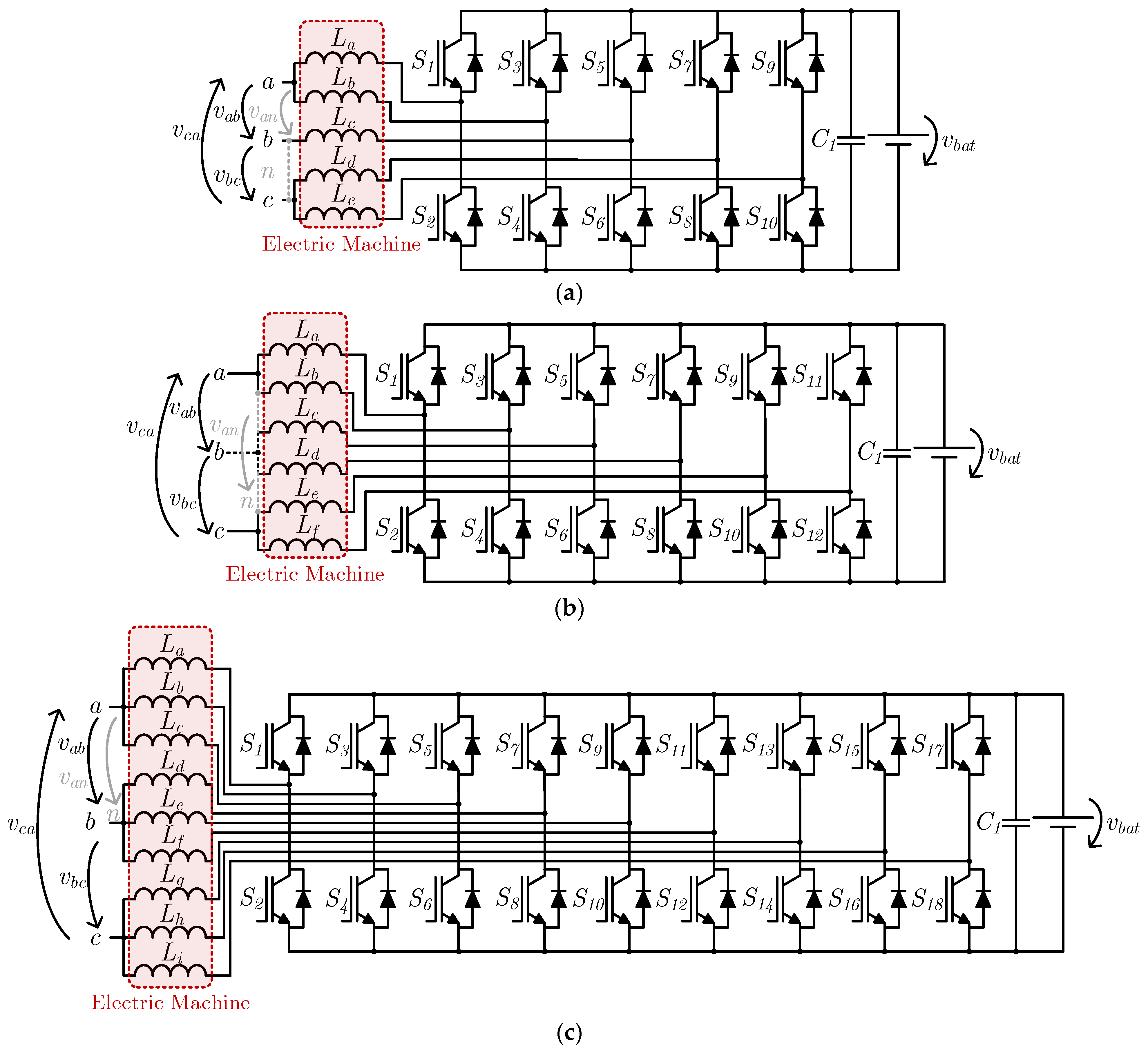
In 2016, I. Subotic et al. proposed an IBC based on a five-phase machine [38]. The same authors analyzed slow [39] and fast [40] battery charging operations using IBCs based on five-phase, six-phase and nine-phase electric machines. In the same year, the authors presented an IBC with galvanic isolation based on six-phase machines, where they simply added a three-phase transformer between the power grid and the converter [41]. It should be noted that these publications regarding multiphase machines only focus on the interface with the power grid (single-phase ac or three-phase ac) and do not consider a dc–dc converter for interfacing with the battery. In the following year, however, the same authors proposed two IBCs with direct interfacing with the power grid, including a bidirectional buck–boost dc–dc converter to interface with the battery. One of these systems is applied to six-phase machines and three-phase ac power grids [42], while the other is applied to nine-phase machines and can be connected to either single-phase or three-phase ac power grids [43]. Figure 19 shows the common structure between the proposed topologies from the power grid interface point of view, i.e., for five-phase (Figure 19a), six-phase (Figure 19b) and nine-phase (Figure 19c) electric machines. Regarding the five-phase topology, when it is connected to a single-phase ac power grid (terminals a, n), one of the terminals contains two stator windings (in this case a) and the other contains three stator windings (in this case n). On the other hand, when connected to a three-phase ac power grid (terminals a, b, c), two stator windings are used in two of the machine phases (in this case a, c) and only one is used in the remaining phase (in this case b). In the case of the six-phase topology, since the phase number is even and a multiple of three, the stator windings are equally divided in both types of interfaces and are assembled in pairs (in the case of a three-phase ac power grid) or in triplets (in the case of a single-phase ac power grid). Finally, for the nine-phase topology, the stator windings are grouped in triplets in both cases, using the three winding groups in the interface with a three-phase ac power grid and only two of them in the interface with a single-phase ac power grid.
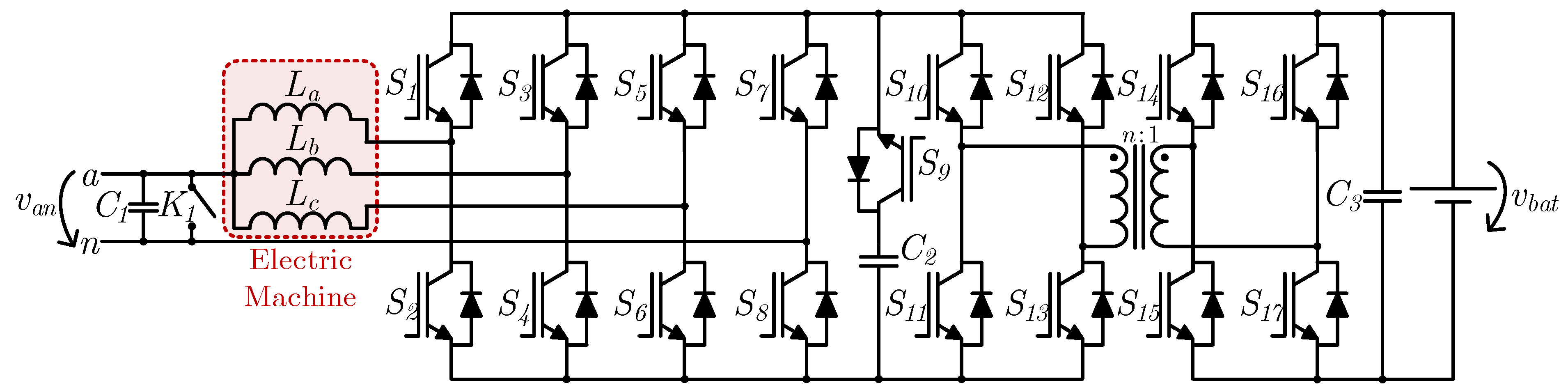
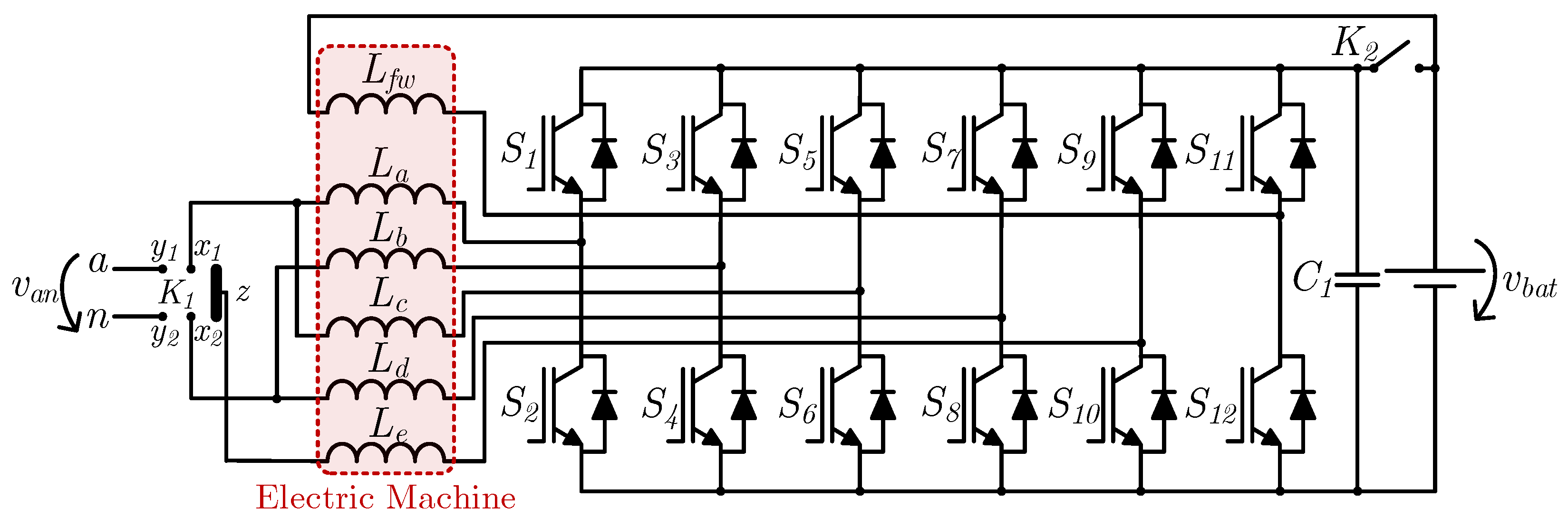
In 2020, M. Tong et al. proposed an IBC based on a five-phase hybrid excitation flux-switching machine, as shown in Figure 20 [44]. As well as the five converter legs (S1–S10) used to energize the machine armature windings (La–Le), an extra leg (S11 and S12) is used to energize a field winding (Lfw) for machine excitation. This topology also contains two contactors (K1 and K2) to switch the operation between traction and battery charging. In traction mode, the contactor K1 connects terminals x1, x2 to terminal z, establishing the neutral point of the five-phase machine. Contactor K2 is closed in this situation, connecting the battery and dc link capacitor C1 in parallel. On the other hand, in battery charging mode, the contactor K1 connects terminal x1 to y1 and x2 to y2, with this pair of terminals representing the connection points to a single-phase ac power grid. Hence, a two-phase interleaved bidirectional full-bridge ac–dc converter is assembled (semiconductors S1–S8 and inductors La–Ld), with the leg formed by semiconductors S9 and S10 and machine winding Le unutilized. In this case, the leg formed by semiconductors S11 and S12 and the machine field winding Lfw, form a bidirectional buck–boost dc–dc converter, where contactor K2 must be kept open in order to separate the battery (low voltage side of the dc–dc converter) from the dc link capacitor C1 (high voltage side of the dc–dc converter). In 2021, the same authors proposed a modification to this system, changing contactor K1 to accommodate the connection to a three-phase ac power grid and thus allowing fast battery charging [45].
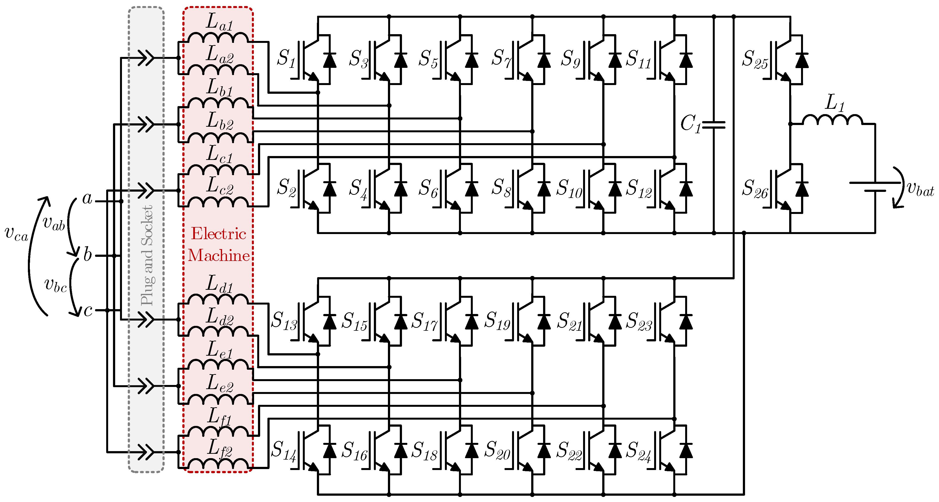
In 2020 also, H. Raherimihaja et al. proposed an IBC based on a six-phase open-end winding machine [46]. As illustrated in Figure 21, this topology is composed of a twelve-leg inverter (S1–S24) to drive the electric machine, as well as an additional leg (S25 and S26) and inductor (L1) that form a bidirectional buck–boost dc–dc converter to connect the inverter dc link to the battery. Instead of using contactors, this system contains a plug and socket to connect the machine terminals to a three-phase ac power grid. The machine windings are connected in pairs, and in this case (battery charging mode), two pairs of windings are connected to each other, where the midpoint of each pair is connected to a given phase of the power grid. With this configuration, it is possible to achieve a four-phase interleaved bidirectional three-phase ac–dc converter, since the twelve inverter legs can be used in an arrangement of four legs per power grid phase. Despite mentioning this feature, the authors do not employ this interleaved operation in the same paper. This system allows bidirectional operation with the power grid, and since it uses a six-phase machine, it allows a battery charging power twice that of the traction power, as well as having fault tolerance capability. In 2021, the same authors proposed a similar system based on a nine-leg inverter and a three-phase nine-winding machine [47], as well as giving a detailed analysis of the design of this type of machine for use in IBCs [48].
3. Comparison between Integrated Battery Chargers
The IBCs reviewed in this paper are compared in this section. The comparison is based on whether contactors are needed to reconfigure the system, whether additional inductors are used to interface the system with the power grid, the type of machine that the system supports and the winding access level that is required (where normal means the conventional phase terminal access), the existence of galvanic isolation between the batteries and the power grid, the capability of bidirectional operation with the power grid and the possibilities for interfacing that they allow in addition to interfacing with the EV’s main electric machine. Table 1 presents the comparison between the 29 IBCs (31 IBCs were presented, but the features of the three IBCs proposed by I. Subotic et al. and V. Katic et al. [38,39,40] are the same except for the number of electric machine phases). The order used for the IBCs in the table is the same as the order in which they appear in the paper.
It can be seen that most of the topologies do not require additional inductors to interface the system with the power grid; however, most of them do require contactors. Topologies that require neither contactors nor additional inductors require electric machine access to at least the neutral point, if not total access to the windings. Regarding bidirectional operation, it can be seen that when no contactors or additional inductors are used, total access to the machine windings is required, with the exception of the system patented by W. Rippel and A. Cocconi in 1992 [13], where only neutral-point access is required but with two three-phase electric machines or one machine with two sets of stator windings. It can also be verified that, when two or more power grid interface possibilities exist, at least neutral-point access is required. If two or more power grid interface possibilities are combined with bidirectional operation, total access to the electric machine windings is mandatory for the presented topologies. Therefore, it can be concluded that, in general, IBCs with higher functionalities have naturally higher requirements, either regarding the electric machine winding access or regarding external components, which is expected from a single set of power converters performing more than its two designed functions (traction and battery charging).
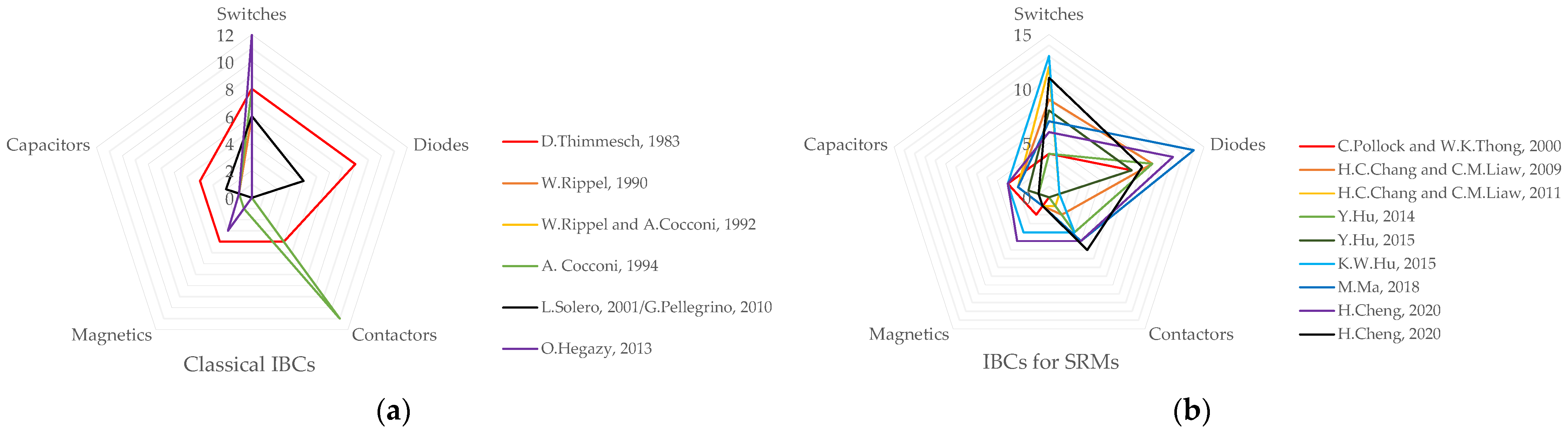
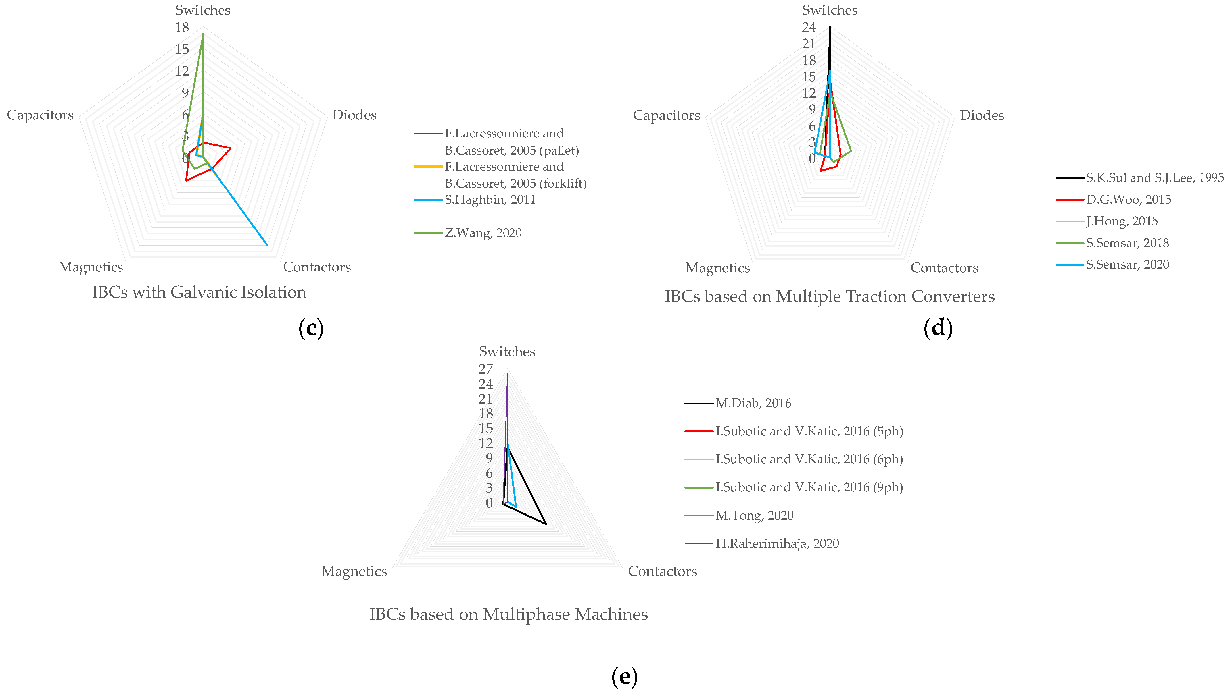
In order to establish a comparison between the IBCs in quantitative terms, Figure 22 presents five radar charts, where the number of switches, diodes, contactors, magnetics and capacitors is represented. Due to the high number of presented IBCs and in order to better analyze the provided information, five radar charts were used instead of a single chart, with each one representing a subsection of Section 2. Figure 22a represents the classical IBCs (Section 2.1), Figure 22b the IBCs for SRMs (Section 2.2), Figure 22c the IBCs with galvanic isolation (Section 2.3), Figure 22d the IBCs based on multiple traction converters (Section 2.4) and Figure 22e the IBCs based on multiphase machines (Section 2.5). The term “switches” refers to fully controlled semiconductors, either IGBTs, MOSFETs or bipolar junction transistors, with or without antiparallel diodes, while the term “diodes” refers to this single component, excluding the antiparallel diodes present in fully controlled semiconductors. “Magnetics” can refer to either inductors or transformer windings, excluding electric machine windings (e.g., one transformer with one primary and one secondary winding contributes two to the magnetics count). The term “capacitors” only counts each capacitor set (as in the capacitor numbering in the IBC figures). It should be noted that Figure 22e has only three comparative metrics, namely, switches, magnetics and contactors, since the diode count is nil and the capacitor count is one for all the topologies presented in this figure.
4. Conclusions
Electric vehicles (EVs) have experienced tremendous growth in the past few years since they are an emissions-free means of transportation at the user level. The power electronics converters present in an EV are based on two main systems that operate only one at a time, namely, the traction system and the battery charging system. This operational nonconcurrence gave rise to the development of integrated battery chargers (IBCs) consisting of a single power electronics system with both functionalities. Several IBCs have been proposed in the literature and patented, and this paper aimed to provide a literature review of the most relevant IBCs. Due to their diversity, the paper divided the analyzed IBCs into five subsections, namely: (1) classical IBCs; (2) IBCs especially developed for switched reluctance machines (SRMs); (3) IBCs with galvanic isolation; (4) IBCs based on multiple traction converters; (5) IBCs based on multiphase machines. After presenting each type, the IBCs were compared both in terms of requirements (e.g., the need for additional inductors or contactors, the type of electric machine needed) and in terms of functionalities (e.g., galvanic isolation, bidirectional operation, power grid interface possibilities). It was verified that topologies that do not require external components such as inductors or contactors usually require special access to the electric machine as well as the conventional phase access. Additionally, some topologies allow interfacing to more than one type of power grid, and in most of these cases it is mandatory to have access to all electric machine windings. The same occurs with bidirectional operation with the power grid, where for topologies with no additional inductors or contactors, electric machine access to at least the neutral point is required. When combining bidirectional operation with more than two types of power grid interfaces, total winding access is a must. For the presented IBCs, it can be concluded that, in general, higher functionalities imply higher requirements, either from the electric machine winding access or from external components such as contactors to reconfigure the system. However, it should be kept in mind that this complexity refers to a single set of power converters performing more than its two designed functions (traction and battery charging), which still represents lower volume, weight and possibly cost than separate power electronics systems for performing the same functions.
Author Contributions
Conceptualization, T.J.C.S., D.P., V.M. and J.L.A.; investigation, T.J.C.S. and D.P.; resources, T.J.C.S. and D.P.; writing—original draft preparation, T.J.C.S.; writing—review and editing, D.P., V.M. and J.L.A.; supervision, V.M. and J.L.A.; funding acquisition, T.J.C.S., V.M. and J.L.A. All authors have read and agreed to the published version of the manuscript.
Funding
This work has been supported by FCT—Fundação para a Ciência e Tecnologia within the R&D Units Project Scope: UIDB/00319/2020. T.J.C.S. is supported by the FCT scholarships SFRH/BD/134353/2017 and COVID/BD/151993/2021.
Conflicts of Interest
The authors declare no conflict of interest.
References
- Dudek, E. The Flexibility of Domestic Electric Vehicle Charging: The Electric Nation Project. IEEE Power Energy Mag. 2021, 19, 16–27. [Google Scholar] [CrossRef]
- Lee, Z.J.; Sharma, S.; Low, S.H. Research Tools for Smart Electric Vehicle Charging: An introduction to the adaptive charging network research portal. IEEE Electrif. Mag. 2021, 9, 29–36. [Google Scholar] [CrossRef]
- Sun, X.; Li, Z.; Wang, X.; Li, C. Technology Development of Electric Vehicles: A Review. Energies 2019, 13, 90. [Google Scholar] [CrossRef] [Green Version]
- Afonso, J.L.; Cardoso, L.A.L.; Pedrosa, D.; Sousa, T.J.C.; Machado, L.; Tanta, M.; Monteiro, V. A Review on Power Electronics Technologies for Electric Mobility. Energies 2020, 13, 6343. [Google Scholar] [CrossRef]
- Sayed, K.; Almutairi, A.; Albagami, N.; Alrumayh, O.; Abo-Khalil, A.G.; Saleeb, H. A Review of DC-AC Converters for Electric Vehicle Applications. Energies 2022, 15, 1241. [Google Scholar] [CrossRef]
- Chakraborty, S.; Vu, H.-N.; Hasan, M.M.; Tran, D.-D.; Baghdadi, M.E.; Hegazy, O. DC-DC Converter Topologies for Electric Vehicles, Plug-in Hybrid Electric Vehicles and Fast Charging Stations: State of the Art and Future Trends. Energies 2019, 12, 1569. [Google Scholar] [CrossRef] [Green Version]
- Pedrosa, D.; Monteiro, V.; Sousa, T.J.C.; Machado, L.; Afonso, J.L. Unified Power Converter Based on a Dual-Stator Permanent Magnet Synchronous Machine for Motor Drive and Battery Charging of Electric Vehicles. Energies 2021, 14, 3344. [Google Scholar] [CrossRef]
- Yilmaz, M.; Krein, P.T. Review of Battery Charger Topologies, Charging Power Levels, and Infrastructure for Plug-In Electric and Hybrid Vehicles. IEEE Trans. Power Electron. 2013, 28, 2151–2169. [Google Scholar] [CrossRef]
- Sousa, T.J.C.; Monteiro, V.; Pedrosa, D.; Machado, L.; Afonso, J.L. Unified Systems for Traction and Battery Charging of Electric Vehicles: A Sustainability Perspective. EAI Endorsed Trans. Energy Web 2021, 8, 170557. [Google Scholar] [CrossRef]
- Thimmesch, D. Integral Inverter/Battery Charger for Use in Electric Vehicles; USA Department of Energy/NASA: Springfield, VA, USA, 1983. [Google Scholar]
- Thimmesch, D. An SCR Inverter with an Integral Battery Charger for Electric Vehicles. IEEE Trans. Ind. Appl. 1985, IA-21, 1023–1029. [Google Scholar] [CrossRef]
- Rippel, W. Integrated Traction Inverter and Battery Charger Apparatus. U.S. Patent 1990. [Google Scholar]
- Rippel, W.; Cocconi, A. Integrated Motor Drive and Recharge System. U.S. Patent 1992. [Google Scholar]
- Cocconi, A. Combined Motor Drive and Battery Charger System. U.S. Patent 1994. [Google Scholar]
- Solero, L. Nonconventional on-board charger for electric vehicle propulsion batteries. IEEE Trans. Veh. Technol. 2001, 50, 144–149. [Google Scholar] [CrossRef]
- Pellegrino, G.; Armando, E.; Guglielmi, P. An Integral Battery Charger with Power Factor Correction for Electric Scooter. IEEE Trans. Power Electron. 2010, 25, 751–759. [Google Scholar] [CrossRef] [Green Version]
- Hegazy, O.; Barrero, R.; Van Mierlo, J.; Lataire, P.; Omar, N.; Coosemans, T. An Advanced Power Electronics Interface for Electric Vehicles Applications. IEEE Trans. Power Electron. 2013, 28, 5508–5521. [Google Scholar] [CrossRef]
- Pollock, C.; Thong, W.K. Low-cost battery-powered switched reluctance drives with integral battery-charging capability. IEEE Trans. Ind. Appl. 2000, 36, 1676–1681. [Google Scholar] [CrossRef]
- Chang, H.-C.; Liaw, C.-M. Development of a Compact Switched-Reluctance Motor Drive for EV Propulsion with Voltage-Boosting and PFC Charging Capabilities. IEEE Trans. Veh. Technol. 2009, 58, 3198–3215. [Google Scholar] [CrossRef]
- Chang, H.; Liaw, C. An Integrated Driving/Charging Switched Reluctance Motor Drive Using Three-Phase Power Module. IEEE Trans. Ind. Electron. 2011, 58, 1763–1775. [Google Scholar] [CrossRef]
- Hu, Y.H.; Song, X.G.; Cao, W.P.; Ji, B. New SR Drive With Integrated Charging Capacity for Plug-In Hybrid Electric Vehicles (PHEVs). IEEE Trans. Ind. Electron. 2014, 61, 5722–5731. [Google Scholar] [CrossRef] [Green Version]
- Hu, Y.; Gan, C.; Cao, W.; Li, C.; Finney, S. Split Converter-Fed SRM Drive for Flexible Charging in EV/HEV Applications. IEEE Trans. Ind. Electron. 2015, 62, 6085–6095. [Google Scholar] [CrossRef] [Green Version]
- Hu, K.W.; Yi, P.H.; Liaw, C.M. An EV SRM Drive Powered by Battery/Supercapacitor with G2V and V2H/V2G Capabilities. IEEE Trans. Ind. Electron. 2015, 62, 4714–4727. [Google Scholar] [CrossRef]
- Ma, M.; Chang, Z.; Hu, Y.; Li, F.; Gan, C.; Cao, W. An Integrated Switched Reluctance Motor Drive Topology with Voltage-Boosting and On-Board Charging Capabilities for Plug-In Hybrid Electric Vehicles (PHEVs). IEEE Access 2018, 6, 1550–1559. [Google Scholar] [CrossRef]
- Cheng, H.; Wang, Z.; Yang, S.; Huang, J.; Ge, X. An Integrated SRM Powertrain Topology for Plug-In Hybrid Electric Vehicles with Multiple Driving and Onboard Charging Capabilities. IEEE Trans. Transp. Electrif. 2020, 6, 578–591. [Google Scholar] [CrossRef]
- Cheng, H.; Wang, L.; Xu, L.; Ge, X.; Yang, S. An Integrated Electrified Powertrain Topology with SRG and SRM for Plug-In Hybrid Electrical Vehicle. IEEE Trans. Ind. Electron. 2020, 67, 8231–8241. [Google Scholar] [CrossRef]
- Lacressonniere, F.; Cassoret, B. Converter used as a battery charger and a motor speed controller in an industrial truck. In Proceedings of the 2005 European Conference on Power Electronics and Applications, Dresden, Germany, 11–14 September 2005; Volume 9, p. 7. [Google Scholar]
- Haghbin, S.; Lundmark, S.; Alakula, M.; Carlson, O. An Isolated High-Power Integrated Charger in Electrified-Vehicle Applications. IEEE Trans. Veh. Technol. 2011, 60, 4115–4126. [Google Scholar] [CrossRef]
- Haghbin, S.; Lundmark, S.; Alakula, M.; Carlson, O. Grid-Connected Integrated Battery Chargers in Vehicle Applications: Review and New Solution. IEEE Trans. Ind. Electron. 2013, 60, 459–473. [Google Scholar] [CrossRef]
- Haghbin, S.; Khan, K.; Zhao, S.; Alakula, M.; Lundmark, S.; Carlson, O. An Integrated 20-kW Motor Drive and Isolated Battery Charger for Plug-In Vehicles. IEEE Trans. Power Electron. 2013, 28, 4013–4029. [Google Scholar] [CrossRef]
- Wang, Z.; Zhang, Y.; You, S.; Xiao, H.; Cheng, M. An Integrated Power Conversion System for Electric Traction and V2G Operation in Electric Vehicles with a Small Film Capacitor. IEEE Trans. Power Electron. 2020, 35, 5066–5077. [Google Scholar] [CrossRef]
- Sul, S.-K.; Lee, S.-J. An integral battery charger for four-wheel drive electric vehicle. IEEE Trans. Ind. Appl. 1995, 31, 1096–1099. [Google Scholar] [CrossRef]
- Woo, D.-G.; Joo, D.-M.; Lee, B.-K. On the Feasibility of Integrated Battery Charger Utilizing Traction Motor and Inverter in Plug-In Hybrid Electric Vehicles. IEEE Trans. Power Electron. 2015, 30, 7270–7281. [Google Scholar] [CrossRef]
- Hong, J.; Lee, H.; Nam, K. Charging method for the secondary battery in dual-inverter drive systems for electric vehicles. IEEE Trans. Power Electron. 2015, 30, 909–921. [Google Scholar] [CrossRef]
- Semsar, S.; Soong, T.; Lehn, P.W. Integrated Single-Phase Electric Vehicle Charging Using a Dual-Inverter Drive. In Proceedings of the 2018 IEEE Transportation Electrification Conference and Expo (ITEC), Long Beach, CA, USA, 13–15 June 2018; pp. 320–325. [Google Scholar]
- Semsar, S.; Soong, T.; Lehn, P.W. On-Board Single-Phase Integrated Electric Vehicle Charger with V2G Functionality. IEEE Trans. Power Electron. 2020, 35, 12072–12084. [Google Scholar] [CrossRef]
- Diab, M.S.; Elserougi, A.A.; Abdel-Khalik, A.S.; Massoud, A.M.; Ahmed, S. A Nine-Switch-Converter-Based Integrated Motor Drive and Battery Charger System for EVs Using Symmetrical Six-Phase Machines. IEEE Trans. Ind. Electron. 2016, 63, 5326–5335. [Google Scholar] [CrossRef]
- Subotic, I.; Bodo, N.; Levi, E. An EV Drive-Train with Integrated Fast Charging Capability. IEEE Trans. Power Electron. 2016, 31, 1461–1471. [Google Scholar] [CrossRef] [Green Version]
- Subotic, I.; Bodo, N.; Levi, E. Single-phase on-board integrated battery chargers for EVs based on multiphase machines. IEEE Trans. Power Electron. 2016, 31, 6511–6523. [Google Scholar] [CrossRef] [Green Version]
- Katic, V.; Subotic, I.; Bodo, N.; Levi, E.; Dumnic, B.; Milicevic, D. Overview of fast on-board integrated battery chargers for electric vehicles based on multiphase machines and power electronics. IET Electr. Power Appl. 2016, 10, 217–229. [Google Scholar] [CrossRef]
- Subotic, I.; Bodo, N.; Levi, E.; Jones, M.; Levi, V. Isolated Chargers for EVs Incorporating Six-Phase Machines. IEEE Trans. Ind. Electron. 2016, 63, 653–664. [Google Scholar] [CrossRef] [Green Version]
- Subotic, I.; Bodo, N.; Levi, E. Integration of Six-Phase EV Drivetrains into Battery Charging Process with Direct Grid Connection. IEEE Trans. Energy Convers. 2017, 32, 1012–1022. [Google Scholar] [CrossRef] [Green Version]
- Bodo, N.; Levi, E.; Subotic, I.; Espina, J.; Empringham, L.; Johnson, C.M. Efficiency Evaluation of Fully Integrated On-Board EV Battery Chargers with Nine-Phase Machines. IEEE Trans. Energy Convers. 2017, 32, 257–266. [Google Scholar] [CrossRef]
- Tong, M.; Cheng, M.; Hua, W.; Ding, S. A Single-Phase On-Board Two-Stage Integrated Battery Charger for EVs Based on a Five-Phase Hybrid-Excitation Flux-Switching Machine. IEEE Trans. Veh. Technol. 2020, 69, 3793–3804. [Google Scholar] [CrossRef]
- Tong, M.; Cheng, M.; Wang, S.; Hua, W. An On-Board Two-Stage Integrated Fast Battery Charger for EVs Based on a Five-Phase Hybrid-Excitation Flux-Switching Machine. IEEE Trans. Ind. Electron. 2021, 68, 1780–1790. [Google Scholar] [CrossRef]
- Raherimihaja, H.J.; Zhang, Q.; Na, T.; Shao, M.; Wang, J. A Three-Phase Integrated Battery Charger for EVs Based on Six-Phase Open-End Winding Machine. IEEE Trans. Power Electron. 2020, 35, 12122–12132. [Google Scholar] [CrossRef]
- Raherimihaja, H.J.; Zhang, Q.; Xu, G.; Zhang, X. Integration of Battery Charging Process for EVs into Segmented Three-Phase Motor Drive with V2G-Mode Capability. IEEE Trans. Ind. Electron. 2021, 68, 2834–2844. [Google Scholar] [CrossRef]
- Zhang, Q.; Raherimihaja, H.J.; Xu, G.; Zhang, X. Design and Performance Analysis of Segmented Three-Phase IPMSM for EVs Integrated Battery Charger. IEEE Trans. Ind. Electron. 2021, 68, 9114–9124. [Google Scholar] [CrossRef]
Figure 1.
EV power electronics structure: (a) conventional; (b) integrated using the machine windings as coupling filters with the power grid; (c) integrated using external inductors as coupling filters with the power grid.
Figure 1.
EV power electronics structure: (a) conventional; (b) integrated using the machine windings as coupling filters with the power grid; (c) integrated using external inductors as coupling filters with the power grid.

Figure 2.
EV IBC proposed by D. Thimmesch in 1983 [10].
Figure 2.
EV IBC proposed by D. Thimmesch in 1983 [10].

Figure 3.
EV IBCs proposed by: (a) W. Rippel in 1990 [12]; (b) W. Rippel and A. Cocconi in 1992 [13]; (c) A. Cocconi in 1994 [14].


Figure 5.
EV IBC proposed by O. Hegazy et al. in 2013 [17].
Figure 5.
EV IBC proposed by O. Hegazy et al. in 2013 [17].

Figure 6.
EV IBC based on SRMs proposed by C. Pollock and W. K. Thong in 2000 [18].
Figure 6.
EV IBC based on SRMs proposed by C. Pollock and W. K. Thong in 2000 [18].

Figure 7.
EV IBCs based on SRMs proposed by H. C. Chang and C. M. Liaw in: (a) 2009 [19]; (b) 2011 [20].


Figure 9.
EV IBC based on SRMs proposed by K. W. Hu et al. in 2015 [23].
Figure 9.
EV IBC based on SRMs proposed by K. W. Hu et al. in 2015 [23].

Figure 10.
IBC for plug-in hybrid vehicles based on SRMs proposed by M. Ma et al. in 2018 [24].
Figure 10.
IBC for plug-in hybrid vehicles based on SRMs proposed by M. Ma et al. in 2018 [24].

Figure 11.
IBCs for plug-in hybrid vehicles based on SRMs proposed by H. Cheng et al. in 2020: (a) [25]; (b) [26].

Figure 12.
EV IBCs with galvanic isolation for industrial EVs proposed by F. Lacressonniere and B. Cassoret in 2005 [27] for application in: (a) pallet trucks; (b) forklifts.
Figure 12.
EV IBCs with galvanic isolation for industrial EVs proposed by F. Lacressonniere and B. Cassoret in 2005 [27] for application in: (a) pallet trucks; (b) forklifts.

Figure 13.
EV IBC with galvanic isolation proposed by S. Haghbin et al. in 2011 [28]: (a) topology; (b) stator winding arrangement for phase a.
Figure 13.
EV IBC with galvanic isolation proposed by S. Haghbin et al. in 2011 [28]: (a) topology; (b) stator winding arrangement for phase a.

Figure 14.
EV IBC with galvanic isolation proposed by Z. Wang et al. in 2020 [31].
Figure 14.
EV IBC with galvanic isolation proposed by Z. Wang et al. in 2020 [31].

Figure 15.
EV IBC proposed by S. K. Sul and S. J. Lee in 1995 [32].
Figure 15.
EV IBC proposed by S. K. Sul and S. J. Lee in 1995 [32].

Figure 16.
EV IBCs based on two traction converters proposed in 2015 by: (a) D. G. Woo et al. [33]; (b) J. Hong et al. [34].

Figure 17.
EV IBCs based on two traction converters proposed by S. Semsar et al. in: (a) 2018 [35]; (b) 2020 [36].

Figure 18.
EV IBC proposed by M. Diab et al. in 2016 [37].
Figure 18.
EV IBC proposed by M. Diab et al. in 2016 [37].

Figure 19.
EV IBCs proposed by I. Subotic et al. and V. Katic et al. in 2016 [38,39,40] based on electric machines with phase counts equal to: (a) five; (b) six; (c) nine.

Figure 20.
EV IBC proposed by M. Tong et al. in 2020 [44].
Figure 20.
EV IBC proposed by M. Tong et al. in 2020 [44].

Figure 21.
EV IBC proposed by H. Raherimihaja et al. in 2020 [46].
Figure 21.
EV IBC proposed by H. Raherimihaja et al. in 2020 [46].

Figure 22.
Radar charts illustrating the quantitative comparison between the presented: (a) classical IBCs; (b) IBCs for SRMs; (c) IBCs with galvanic isolation; (d) IBCs based on multiple traction converters; (e) IBCs based on multiphase machines.
Figure 22.
Radar charts illustrating the quantitative comparison between the presented: (a) classical IBCs; (b) IBCs for SRMs; (c) IBCs with galvanic isolation; (d) IBCs based on multiple traction converters; (e) IBCs based on multiphase machines.


Table 1.
Qualitative comparison between the presented IBCs.
| Proposed IBC | Contactors | Additional Inductors | Electric Machine Type | Machine Access | Galvanic Isolation | Bidirectional Operation | Interface Possibilities |
|---|---|---|---|---|---|---|---|
| D. Thimmesch (1983) [10] | Yes | No | 3ph | Normal | Yes | No | 1ph |
| W. Rippel (1990) [12] | No | Optional | 3ph | Normal | No | No | 1ph |
| W. Rippel, A. Cocconi (1992) [13] | No | No | 2 × 3ph/1 × 3ph (w/2 stators) | Neutral point | No | Yes | 1ph |
| A. Cocconi (1994) [14] | Yes | Optional | 3ph | Total | No | Yes | 1ph, 3ph |
| L. Solero (2001) [15] | No | No | 3ph | Neutral point | No | No | 1ph |
| G. Pellegrino (2010) [16] | No | No | 3ph | Neutral point | No | No | 1ph |
| O. Hegazy (2013) [17] | No | Yes | 3ph | Normal | No | Yes | 1ph |
| C. Pollock, W. K. Thong (2000) [18] | No | Yes | 2ph SRM | Neutral point | Yes | No | 1ph |
| H. C. Chang, C. M. Liaw (2009) [19] | Yes | No | 4ph SRM | Total | No | No | 1ph |
| H. C. Chang, C. M. Liaw (2011) [20] | Yes | No | 4ph SRM | Total | No | Yes | 1ph |
| Y. Hu et al. (2014) [21] | Yes | No | 3ph SRM | Neutral point | No | No | 1ph, 3ph, dc |
| Y. Hu et al. (2015) [22] | No | No | 4ph SRM w/2 stators | Neutral point | No | No | 1ph, 3ph, dc |
| K. W. Hu et al. (2015) [23] | Yes | Yes | 4ph SRM | Total | No | Yes | 1ph, 2ph |
| M. Ma et al. (2018) [24] | Yes | No | 3ph SRM | Total | No | No | 3ph |
| H. Cheng et al. (2020) [25] | Yes | No | 3ph SRM | Neutral point | No | No | 1ph |
| H. Cheng et al. (2020) [26] | Yes | No | 3ph SRM | Total | No | No | 1ph |
| F. Lacressonniere, B. Cassoret (2005) [27] (For pallet trucks) | Yes | No | Brushed dc | Total (just 2) | Yes | No | 1ph |
| F. Lacressonniere, B. Cassoret (2005) [27] (For forklifts) | Yes | No | 3ph wound rotor induction | Normal | Yes | Yes | 3ph |
| S. Haghbin et al. (2011) [28] | Yes | No | 3ph (4 windings per phase) | Total | Yes | Yes | 1ph, 3ph |
| Z. Wang et al. (2020) [31] | Yes | No | 3ph | Neutral point | Yes | Yes | 1ph |
| S. K. Sul, S. J. Lee (1995) [32] | Yes | No | 4 × 3ph | Neutral point | No | Yes | 1ph |
| D. G. Woo et al. (2015) [33] | Yes | Optional | 2 × 3ph | Neutral point | No | No | 1ph |
| J. Hong et al. (2015) [34] * | - | - | 3ph | Total | - | - | - |
| S. Semsar et al. (2018) [35] | Yes | No | 3ph | Total | No | No | 1ph |
| S. Semsar et al. (2020) [36] | No | No | 3ph | Total | No | Yes | 1ph |
| M. Diab et al. (2016) [37] | Yes | No | 6ph | Total | No | Yes | 3ph |
| I. Subotic et al., V. Katic et al. (2016) [38,39,40] | No | No | 5ph, 6ph, 9ph | Total | No | Yes | 1ph, 3ph |
| M. Tong et al. (2020) [44] | Yes | No | 5ph hybrid excitation flux switching | Total | No | Yes | 1ph |
| H. Raherimihaja et al. (2020) [46] | No | No | 6ph | Total | No | Yes | 3ph |
* An interface with the power grid is not considered.
Publisher’s Note: MDPI stays neutral with regard to jurisdictional claims in published maps and institutional affiliations. |
© 2022 by the authors. Licensee MDPI, Basel, Switzerland. This article is an open access article distributed under the terms and conditions of the Creative Commons Attribution (CC BY) license (https://creativecommons.org/licenses/by/4.0/).
Share and Cite
MDPI and ACS Style
Sousa, T.J.C.; Pedrosa, D.; Monteiro, V.; Afonso, J.L. A Review on Integrated Battery Chargers for Electric Vehicles. Energies 2022, 15, 2756. https://doi.org/10.3390/en15082756
AMA Style
Sousa TJC, Pedrosa D, Monteiro V, Afonso JL. A Review on Integrated Battery Chargers for Electric Vehicles. Energies. 2022; 15(8):2756. https://doi.org/10.3390/en15082756
Chicago/Turabian StyleSousa, Tiago J. C., Delfim Pedrosa, Vitor Monteiro, and Joao L. Afonso. 2022. "A Review on Integrated Battery Chargers for Electric Vehicles" Energies 15, no. 8: 2756. https://doi.org/10.3390/en15082756
Note that from the first issue of 2016, this journal uses article numbers instead of page numbers. See further details here.