
The Impact of Outdoor Temperatures on the Efficacy of Natural Ventilation and Smoke Exhaust Systems


Faculty of Process and Environmental Engineering, Lodz University of Technology, 90-924 Lodz, Poland
*
Author to whom correspondence should be addressed.
Energies 2022, 15(3), 933; https://doi.org/10.3390/en15030933
Submission received: 16 November 2021
/
Revised: 4 January 2022
/
Accepted: 22 January 2022
/
Published: 27 January 2022
(This article belongs to the Topic Sustainable Built Environment)
Abstract
:Natural smoke control systems in staircases are one of the available systems used for the protection of escape routes from smoke and are one of the most utilised for medium to high rise buildings. However, their effectiveness (as well as other ventilation systems) is strongly dependent on the weather conditions, especially the outdoor temperature. This paper describes the results of real-scale experiments of the airflow in a staircase’s natural smoke exhaust system. The experimental staircase was localised in a medium-high building, “LabFactor” at the Lodz University of Technology in Poland. The experiments were performed over a period of six months, from February to July 2019, and included measurements of external and internal air temperature as well as the airflow through the staircase. The results obtained enabled an evaluation of the effectiveness of the ventilation and natural smoke exhaust system in the staircase, in relation to external temperatures. It was found that natural smoke exhaust systems could operate below an acceptable level of effectiveness for nearly 25% of the year. The experimental results were confirmed with CFD simulations.
1. Introduction
Staircases allow people to move between levels of a multistorey building. In the event of a threat, such as a fire, they also enable the building occupants to escape. In addition, they provide rescue teams with the opportunity to reach the source of the fire. Consequently, smoke and heat ventilation systems for staircases play a vital role in the building’s safety equipment, as highlighted by European Guidelines [1].
Depending on the purpose of the building and its height, Polish regulations [2] specify whether a natural smoke exhaust system or pressure differential systems should be used for smoke control in staircases.
The use of natural smoke exhaust systems for staircases has a long history. They are relatively simple in their use but still generate doubts as to how effective they really are. Furthermore, the methodology of calculation has caused concern. In Poland, the requirement of their use is specified in their Building Regulations [2], but the method of calculation is not clearly defined. Designers can choose from a number of national documents (e.g., [3,4]), as well as guidelines developed by other countries [1,5]. The design procedure for natural smoke exhaust systems in European countries is based mostly on building height and staircase area [6]. The CFPA guidance [1] indicates a number of additional restrictions that should be taken into account [3] for additional factors resulting from irregular shapes of staircases. The Standard itself [3], which is most often used, is often criticised for obsolescence (published in 2001), as it lacks relevance to modern facilities, and the calculation process is independent of the potential fire size and weather conditions [7].
In this paper examining the influence of hot smoke and fire gases on the natural convection in the staircase, space was not taken into account because during a fire, in the period when the evacuation takes place (the initial stage of the fire), the amount of smoke generated is relatively small and strongly cooled by mixing with the surrounding air. Therefore, it was assumed that the smoke entering into the staircase could only improve the operation of the ventilation and natural smoke exhaust system to a limited extent.
The impact of the location and power of the fire on the operation of the natural smoke exhaust system will be analysed in the next stage of the research.
The research conducted around the world focuses mainly on tall buildings [8,9,10] and overpressure methods of protecting staircases against smoke [11]. Natural smoke exhaust systems are analysed much less frequently, and are mainly based on simulation models [7,8,12,13,14,15] or small-scale experimental studies [9,16]. Nevertheless, the conducted research focuses most often on one of the two aspects of smoke extraction: the influence of the building height [1,4] or the influence of wind on the smoke removal [17] and stack effect [13,14]. The research considers up to a dozen or so selected variants [8].
Tests of the “chimney draft” carried out over an extended period (6 months), considering both the influence of wind and other external factors, as well as the geometry of the staircase, are unique. Such investigations are not found in the available literature.
The data collected on the basis of the performed measurements will allow for the validation of the calculation model and verify the feasibility of the possible effects of gravitational smoke removal.
The direction and speed of the wind were recorded in real studies and had an impact on the obtained measurement results. However, the wind influence was not analysed in this paper. For this purpose, the results of real measurements with low wind speed (<0.5 m/s) were selected for the comparative analysis of the CFD simulation results.
Whether the cheapest method of staircase smoke extraction maintains the hazard at an acceptable level during evacuation will also be examined.
- providing people with an opportunity to escape from the building without endangering themselves when leaving the room on fire,
- enabling the operation of the fire brigade,
- maintaining an acceptable level of smoke in the staircase space,
- protection of the building structure through the controlled removal of smoke and heat (by-products of combustion),
All the above objectives are achieved by removing smoke and other gaseous combustion products from the staircase space. However, their efficacy is strongly dependent on the weather conditions, especially the outdoor temperature. In order to assess natural smoke exhaust systems in medium-high buildings under various weather conditions, experiments of the airflow efficiency through a damper were carried out.
The article is divided into several parts. At first, the mechanism of the natural smoke exhaust system will be introduced. Then, then the measuring stand and the obtained results of experimental tests will be presented. In the following, the CFD model will be presented with the obtained simulation results. The obtained results of the experimental research will be compared with the simulation results. Conclusions from the simulations and measurements carried out will be presented in the last part of the article.
2. Smoke and Heat Ventilation Systems
2.1. Type of Smoke and Heat Ventilation Systems
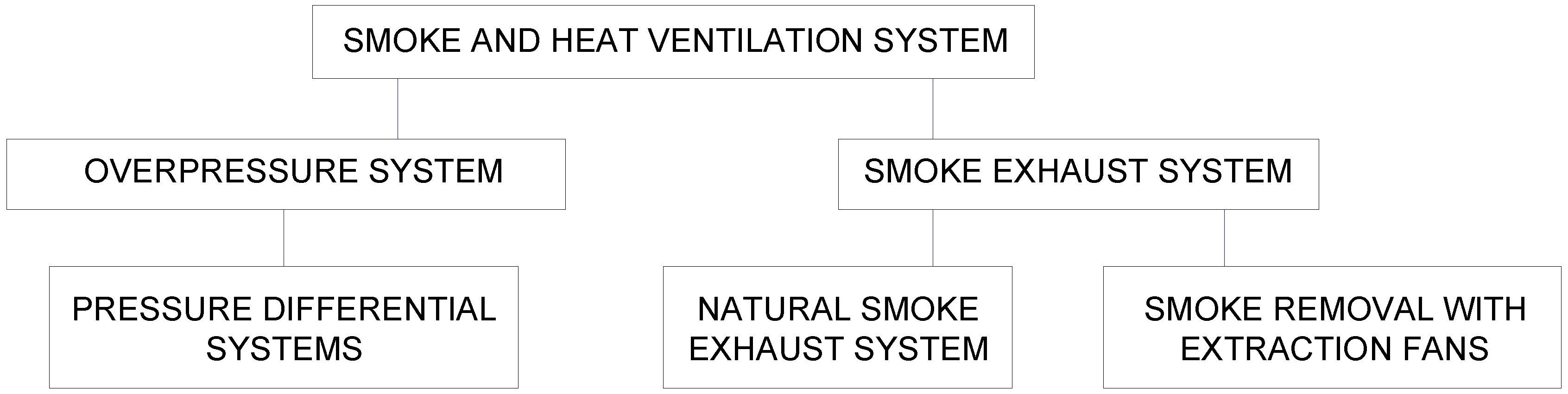
The Polish regulations [2] identify that the smoke and heat ventilation system requirement depends on the building’s type and height. Buildings from 12 to 25 m high are called medium-high [2] and are the subject of this article. Following the technical conditions [2], staircases in these buildings must be equipped with natural smoke exhaust or pressure differential systems. Figure 1 shows the options for smoke control systems for staircases.
The most popular solutions of smoke and heat ventilation systems in medium-high building staircases are:
For the medium-high buildings, the regulations allow for each of the systems mentioned above [2]. Given that cost is an integral consideration, the first and simplest option is chosen most often. The second option is used in situations when a pure natural smoke exhaust system is not viable, e.g., due to the staircase location inside the building, without direct access to external walls. The third solution is rarely applied due to much higher implementation costs than the others (both in terms of initial investment and longer term operations). Based on the above, only the natural smoke exhaust system will be considered, even though this option is the most dependent on weather conditions.
2.2. Elements of a Natural Smoke Exhaust System
The components of typical natural smoke exhaust systems include:
- an automatic smoke damper installed in the roof of the building or a smoke exhaust window in the wall on the highest floor of the building,
- an automatic entrance door to the staircase or window in the wall on the ground floor for the makeup air supply,
- smoke detectors located under the ceiling of each floor for smoke detection and fire alarm activation,
- self-closing elements in each door to the staircase for smoke spread propagation limitation,
- a control panel for the automatic smoke exhaust system activation,
- manual smoke exhaust system activation control.
To properly operate the natural smoke exhaust system, the external door and smoke damper should be open simultaneously. Otherwise, there is no airflow through the staircase [15].
Given the above, it is worth noting that the requirement of automatic activation of natural smoke exhaust devices in medium-high buildings in Poland appeared as recently as 2018. However, there are still no regulations for the automatic opening of external doors (inlet air opening), which strongly decreases the effectiveness of existing systems.
2.3. Effect of Wind on the Natural Smoke Exhaust System Operation
The natural smoke exhaust system is very sensitive to changing weather conditions, especially the outside temperature. Many publications also draw attention to significant changes in the effectiveness of the system operation depending on the speed and direction of the wind (e.g., [1,20,21]). None of the currently used methods take this element into account to calculate components of the natural smoke exhaust system. Depending on the external conditions, the wind can raise or lower the system efficacy by changing pressure conditions in the building and its external environment.
2.4. Stack Effect
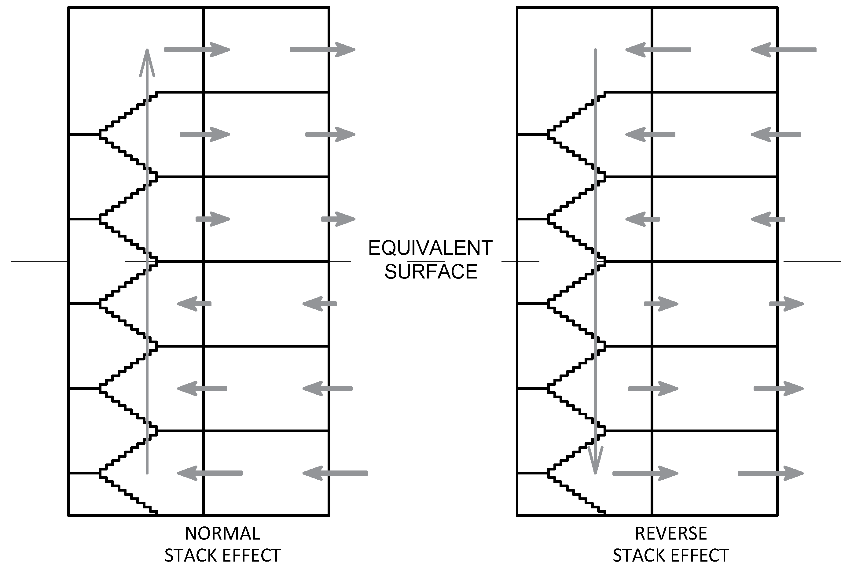
The stack effect has already been well recognised and described mathematically as presented in [15,22]. It is based on the pressure difference between the staircase space and the outdoors, caused by the difference in air temperature and its density inside and outside of the staircase. As a consequence, a natural flow of air from the bottom to the top of the staircase is generated. This phenomenon is clearly visible in the winter months, when the temperature differences are the greatest. In summer, when the external temperature is higher than the inner, the natural air movement in the staircase flows in the opposite direction (downwards). This phenomenon is called the reverse stack effect. The pressure distribution during normal and reverse stack effects is shown in Figure 2.
3. Real Scale Experiments
3.1. The Experimental Layout
In order to verify the efficiency of the smoke exhaust system under different weather conditions, a real scale experiment of the airflow in a staircase’s natural smoke control system was conducted. The experiments were carried in the LabFactor building at the Lodz University of Technology. The building is 19.8 m high and, according to Polish law [2], belongs to the group of medium-high buildings (<25 m).
Experimental data of the internal and external temperature and the airflow through the smoke damper was saved automatically and stored on a programmable controller.
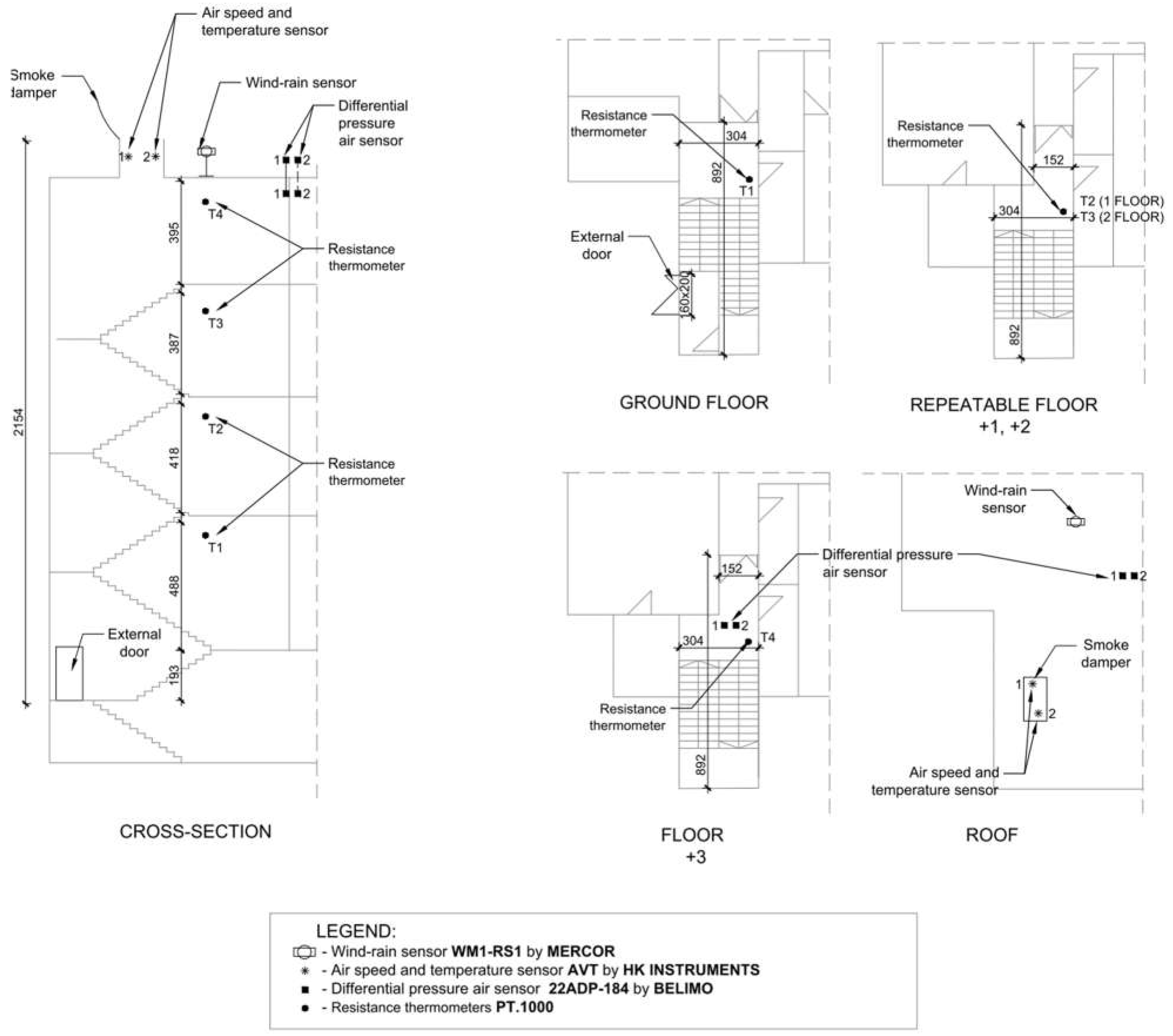
The measurement and digital data acquisition system consisted of the following elements:
- resistance thermometers PT.1000, located under the ceiling of each floor, in the space of the flight of stairs (Figure 3), measurement range: −25 + 480 °C; measurement accuracy ±0.3 °C,
- wind-rain sensor WM1-RS1 by MERCOR, located on the roof of the building (Figure 3),
- two airspeed and temperature sensors: AVT by HK INSTRUMENTS, located in the opening of the smoke damper, measurement range: 0–10 m/s; measurement accuracy ±0.3 °C; measurement accuracy <0.5 m/s + 5% from reading,
- two differential pressure sensors 22ADP-184 by BELIMO, located on the 3rd floor and at the roof, measurement range: −100–2500 Pa; measurement accuracy ≤500 Pa: ±5 and >500 Pa: ±10 Pa ± 0.3 °C,
- free-programmable controller AVD8400/C/L/U by ELIWELL, which performed a digital acquisition of experimental data and controlled the system of opening and closing of the smoke damper and external doors.
To obtain the statistical database covering the full range of external temperatures during the year (outside air temperatures below 0 °C and above 30 °C), measurements were taken twice a day (at 3.00 a.m. and 3.00 p.m.) for six months (from February to July 2019). Each measurement cycle provided 10 min for the opening of the smoke damper and the external door on the ground floor of the building (Figure 3). During this time, the following parameters were measured and recorded at 2 s intervals: external air temperature, wind speed and direction, internal air temperature, the pressure difference between the staircase and the outside environment, and the airflow velocity through the smoke damper.
3.2. Measuring Instruments
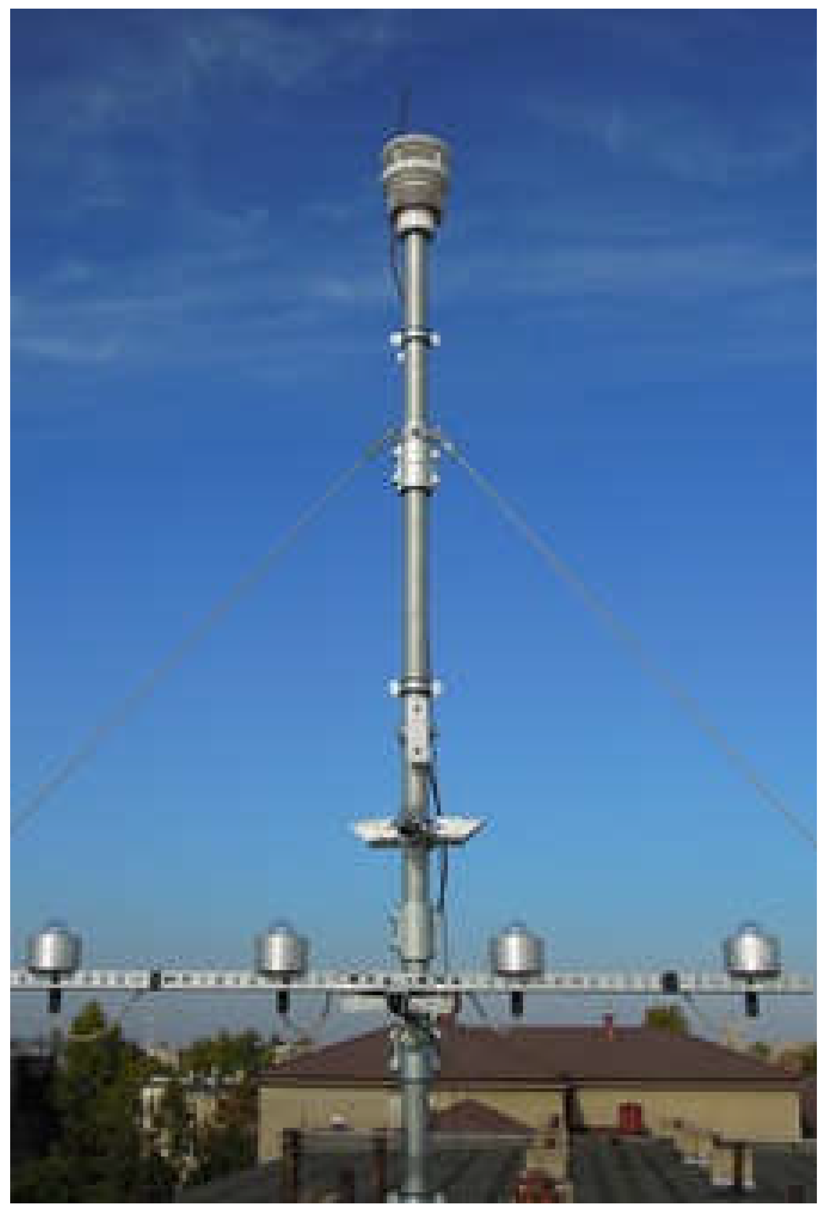
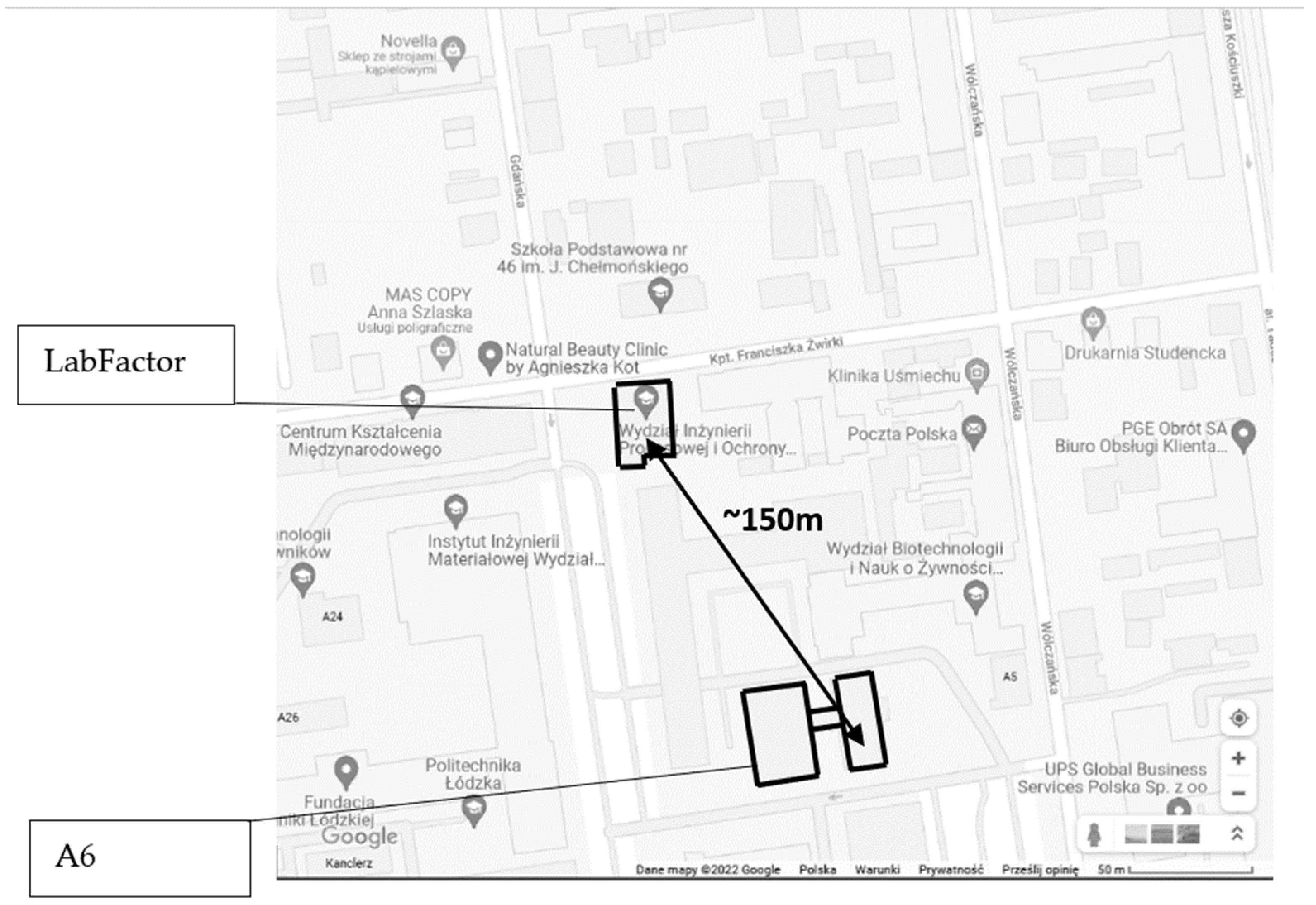
The outdoor air temperature and wind velocity data were taken from a meteorological station located in an adjacent building of the Lodz University of Technology approx. 150 m from the test building (Figure 4 and Figure 5). The close proximity between the buildings allowed us to assume that the measured values correspond to the air temperature in the test building.
The installed measuring equipment in the test building generated limitations in terms of the possible location—none of the installed devices could limit the functionality of the tested staircase. Therefore, the temperature measurement in the door opening and the volumetric flow rate flow through the external door could not be measured.
3.3. Visualisation of the Airflow through the Smoke Damper in a Staircase
Before starting the analysis of the experimental data, the nature of the airflow phenomenon through the open smoke damper was visualised using numerical simulations created on the Femlab 3.2 application [24]. The simulations assessed the air flowing through the staircase and smoke damper.
The Femlab program uses fine elements equations. Flow movement and balance movements are described by Navier–Stokes equation in the form of Equation (1).
where:
u (m/s)—denotes the velocity vector (m/s),
t (s)—time,
ƞ (N/m2)—fluid viscosity,
p (Pa)—pressure,
ρ (kg/m3)—density of the fluid,
g (m/s2)—gravity acceleration,
T (K)—temperature and thermal expansion coefficient.
Equation (1) was modified by the buoyancy term on the right hand side for the lifting force due to thermal expansion, which are movement forces for free convection (Equation (2)).
The transport of heat can be described by the following Equation (3):
The density of the fluid (assuming as an ideal gas) was calculated from Equation (4):
where:
M—molecular weight of the gas (air), (kg/mol),
R—specific gas constant, (J/(mol × K)).
The software assumes a steady-state flow (∂/∂t) and non-compressible state and fulfils ideal gas conditions as in Equation (4).
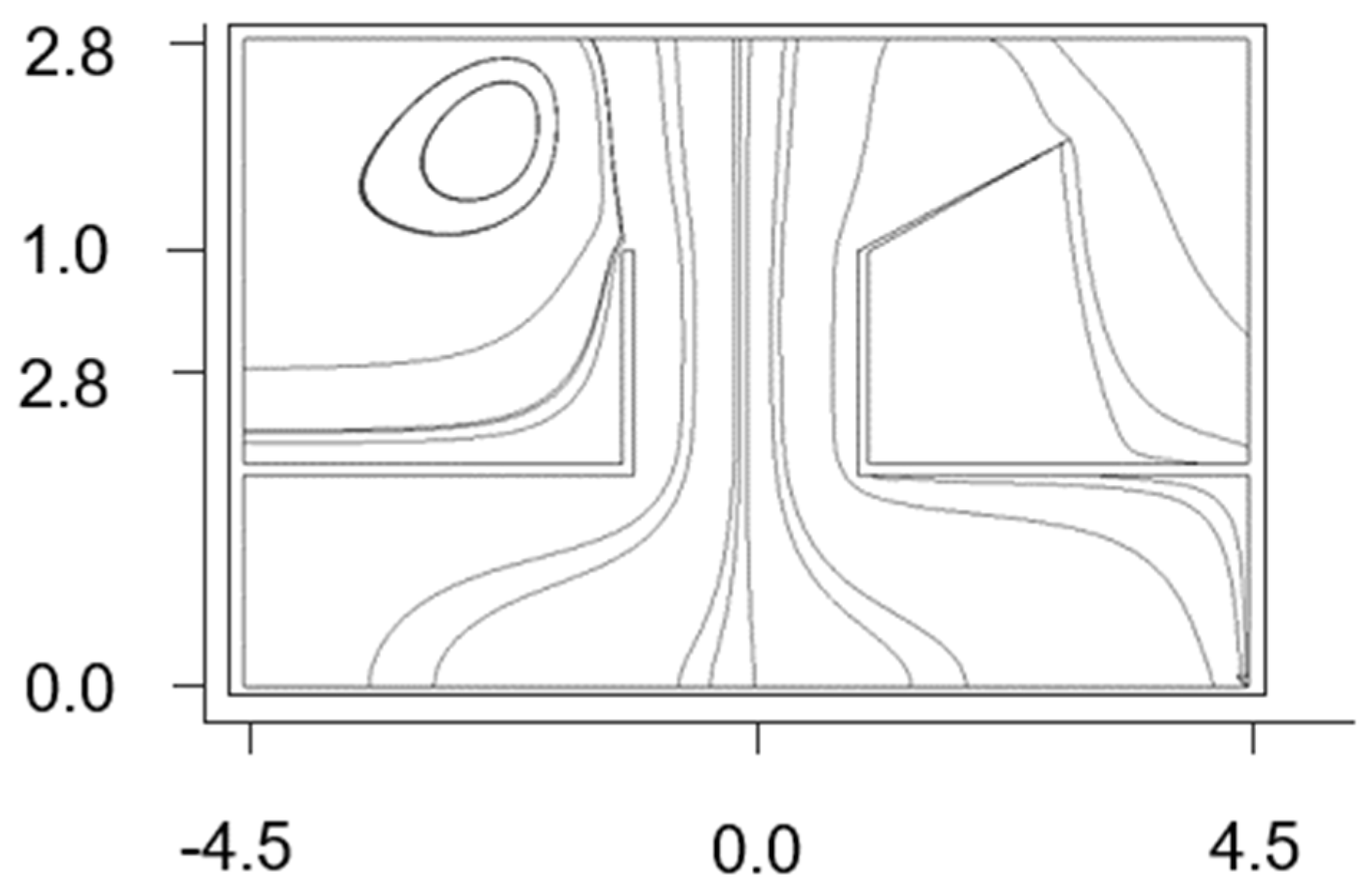
Simulation of the airflow through an asymmetrical smoke damper was based on the free jet flow parameters. The results of Femlab numerical simulation are presented in Figure 6 and Figure 7.
Figure 6 presents the nature of the air flowing through the smoke damper under steady state (no wind) conditions.
During these measurements, it was not possible to control the speed and direction of the wind. This was a reason for the large fluctuations in experimental data and led to the discounting of some results.
3.4. The Influence of the Stack Effect Phenomenon
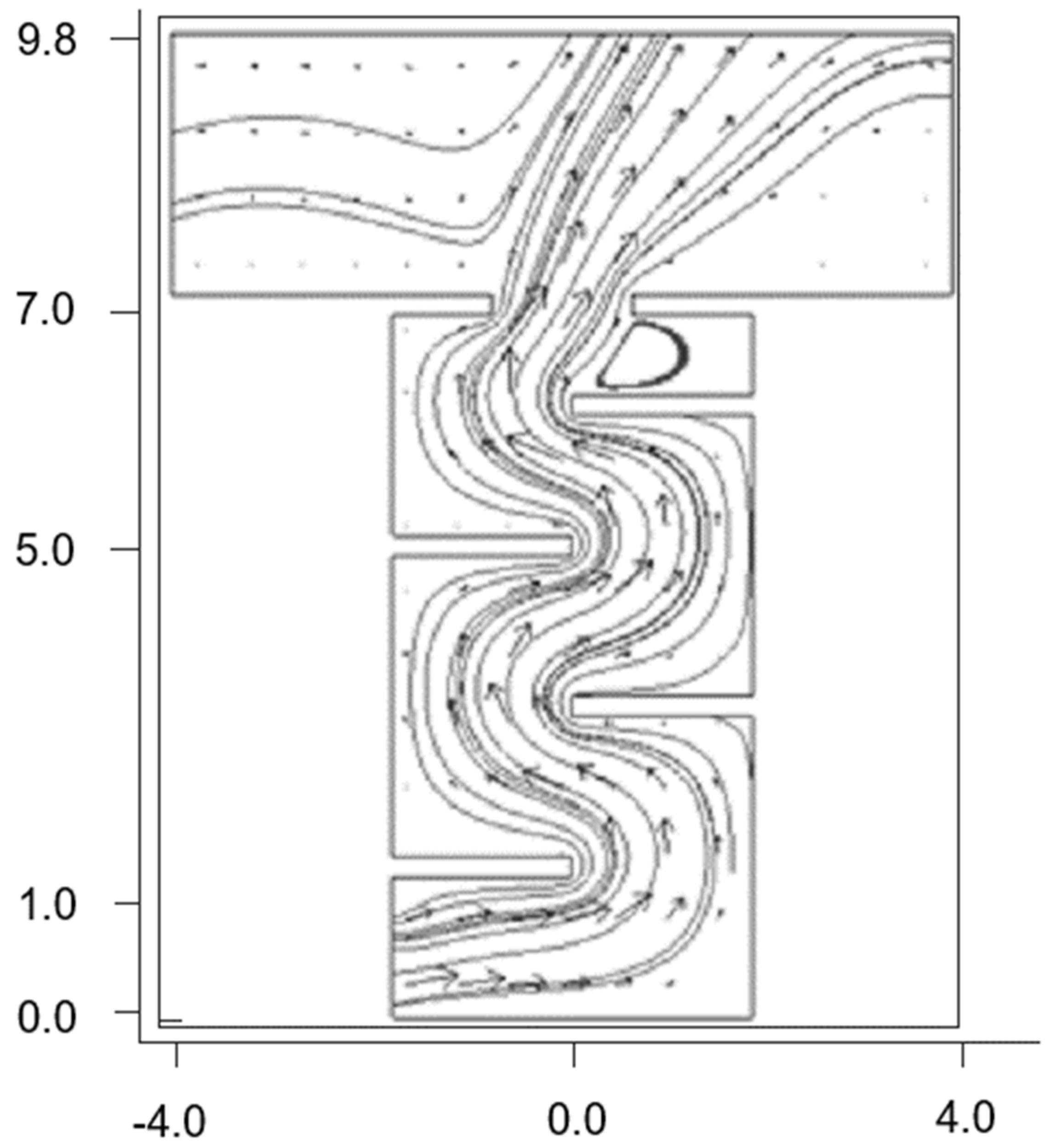
As mentioned earlier, the airflow through a staircase could be described as the stack effect phenomenon. The natural (gravitational) airflow through the chimney/vertical ventilation duct is a relatively simple phenomenon caused by the difference in temperature (density) of air inside the duct and the surrounding air. Airflow direction, inside the chimney (staircase), between the inlet and outlet openings, depends on the temporary temperature distribution. In the case of a staircase (treated here as a special type of chimney), there are obstacles inside the channel: stair steps, landings, and walls limiting the staircase space. All of these obstacles were included in the model prepared in Femlab 3.2, as shown in Figure 7. On the x and y axes, the dimensions (in meters) of the staircase with the surroundings are marked.
4. Experimental Results
As it was mentioned earlier, the airflow through the staircase induced by natural convection was verified for various external air temperatures for winter and summer. The extreme values of temperatures during the measurements were −2.0 and +35.5 °C.
4.1. Internal Temperature Variability in the Staircase
The air temperature inside the staircase was regulated by several panel heaters located on the landings and remained around 20 °C. In the summer, the temperature in the staircase space was not regulated and varied from 21 to 27 °C depending on the weather conditions.
During the experiment, when the smoke damper and the door opened, the internal staircase temperature changed. All presented air temperature changes covered a 10 min period of a single measurement while the outside air flowed through the staircase.
Figure 8a shows the representative temperature in winter when the external air temperature was equal to Tout = −2.0 °C. This was the lowest value achieved for the external temperature in the measurements. Initial values of internal temperature in the staircase in this test were in the range of Tin = 18.7–20.2 °C. The lowest value of the initial temperature was measured by the T1 sensor (located under the ceiling of the ground floor) and the highest by the T3 sensor (located under the floor +2).
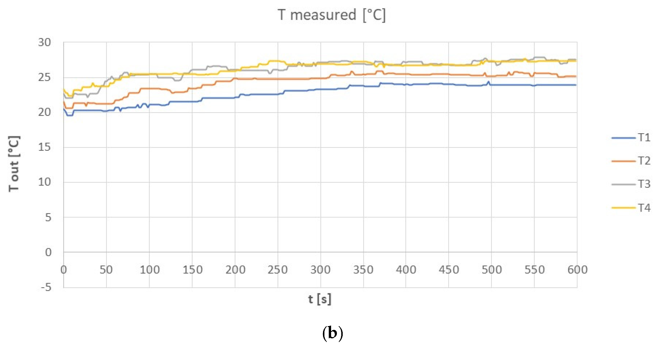
Figure 8b shows the representative temperature in the staircase in summer, for the external air temperature, was equal to Tout = 35.5 °C. This was the highest measured value of the external temperature. Initial values of internal temperature in the staircase in the same test were in the range of Tin = 20.5–23.3 °C. The lowest temperature value was measured by the T1 sensor (located under the ground floor ceiling) and the highest by T4 (located under the floor ceiling, +3).
The graphs in Figure 8a,b present the influence of airflow through the staircase on the internal temperature in the staircase (position of thermometers T1–T1 is shown in Figure 3).
The air temperature variability in the staircase was characterised by a gradual decrease in winter and an increase in summer. The change of air temperature was observed first at the sensors located closest to the external door in the winter season, and to the smoke damper in the summer, and later at the sensors located further away.
4.2. Air Volume Flow Variability through the Smoke Damper
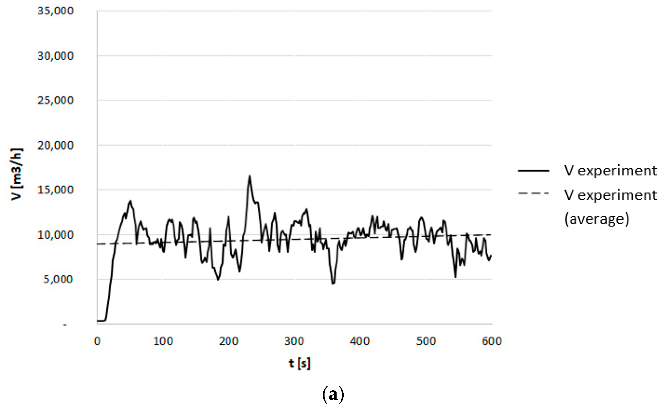
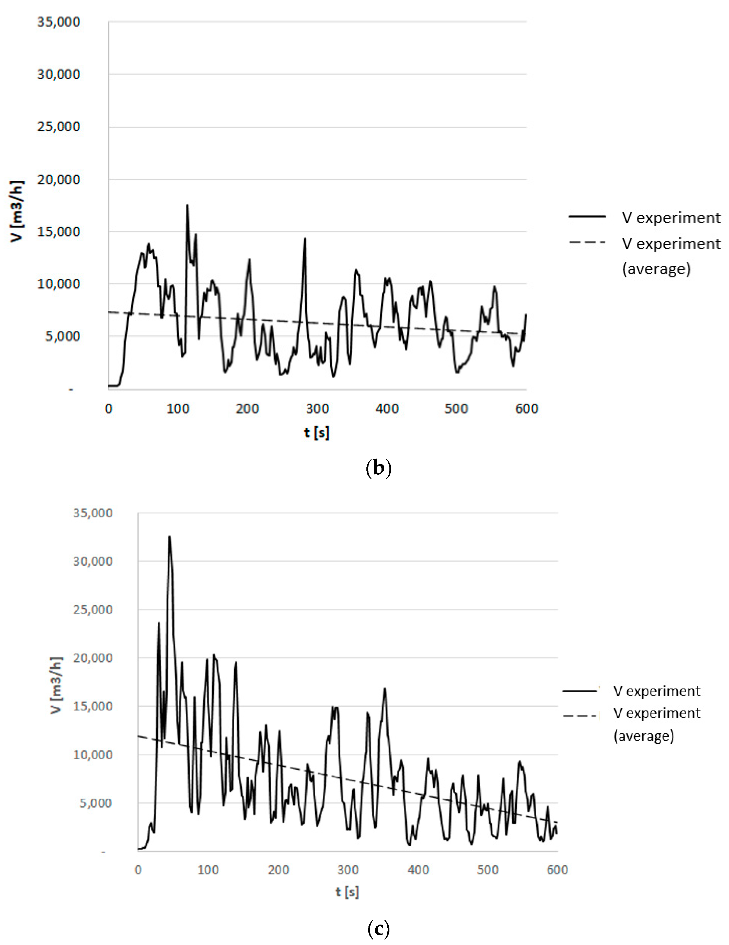
After activation of the natural smoke exhaust system, a flow of air in the space of the staircase was generated. The direction of the airflow under the no wind condition depended on the current temperature difference between the external environment and the space of the cage. The smoke damper worked as an exhaust vent when the outside air temperature was lower than the internal temperature. While the outside temperature was higher than the internal temperature, the smoke damper worked as a makeup opening. Moreover, the greater the internal and external temperatures difference, the greater the observed airflow volume through the staircase (Figure 9).
5. Numerical Model of the Analysed Geometry of the Staircase in the FDS Program
5.1. Grid Sensitivity Analysis
After the initial preparation of the staircase model, the quality of the obtained results was verified in the simulation program, taking into account the number of calculation cells and the calculation time. For the comparative analysis of the obtained results, the temperature distribution in the staircase space was taken into account. The list of the adopted cell sizes, calculation time, and the obtained results are presented in Table 1 for the 15th and 60th seconds of the simulation.
As can be seen in Table 1, the size of the cell has a significant impact on the simulation time and accuracy of the obtained results. The size of the cells also affects the accuracy of the representation of the model. Based on the analysis of Table 1, for the analysed staircase a mesh with a grid size equal to 18 cm was chosen. A further increase in the computational mesh density generated a significant increase in computation time (five times longer computation time mesh of 0.18 m than 0.09 m) while the simulation results were nearly the same. At the same time, the mesh of 0.18 m corresponded to the height of the stair step and allowed the most accurate representation of the analysed staircase.
5.2. Boundary Conditions
Based on the conducted experiments, a CFD model of the tested staircase was developed. The simulations were created using the Fire Dynamics Simulator 6.7.6 program with graphic overlay PyroSim v.2021.3.0901.
The calculation model of the staircase included the staircase space and took into account obstacles in staircase space: stairs, landings, and doors. The air inflow was realised through the air supply element located in the lower part of the staircase—the open external door and the exhaust through the automatically opened smoke damper. To determine the air temperature inside the staircase, the model includes several measurement planes. The boundary conditions for simulations assumed all the same values as the conducted experiments. The adopted outside and inside air temperature values were in the following variants:
- (1)
- Tout = −2.0 °C; Tin = +20.0 °C.
- (2)
- Tout = +15.4 °C; Tin = +20.0 °C.
- (3)
- Tout = +35.4 °C; Tin = +21.5 °C.
Based on the grid sensitivity analysis, the mesh of 0.18 × 0.18 × 0.18 was adopted for further simulations. The LabFactor building model size was (X) 7.92 × (Y) 10.08 × (Z) 27.00, so the number of calculation cells for the assumed mesh size was 369,600.
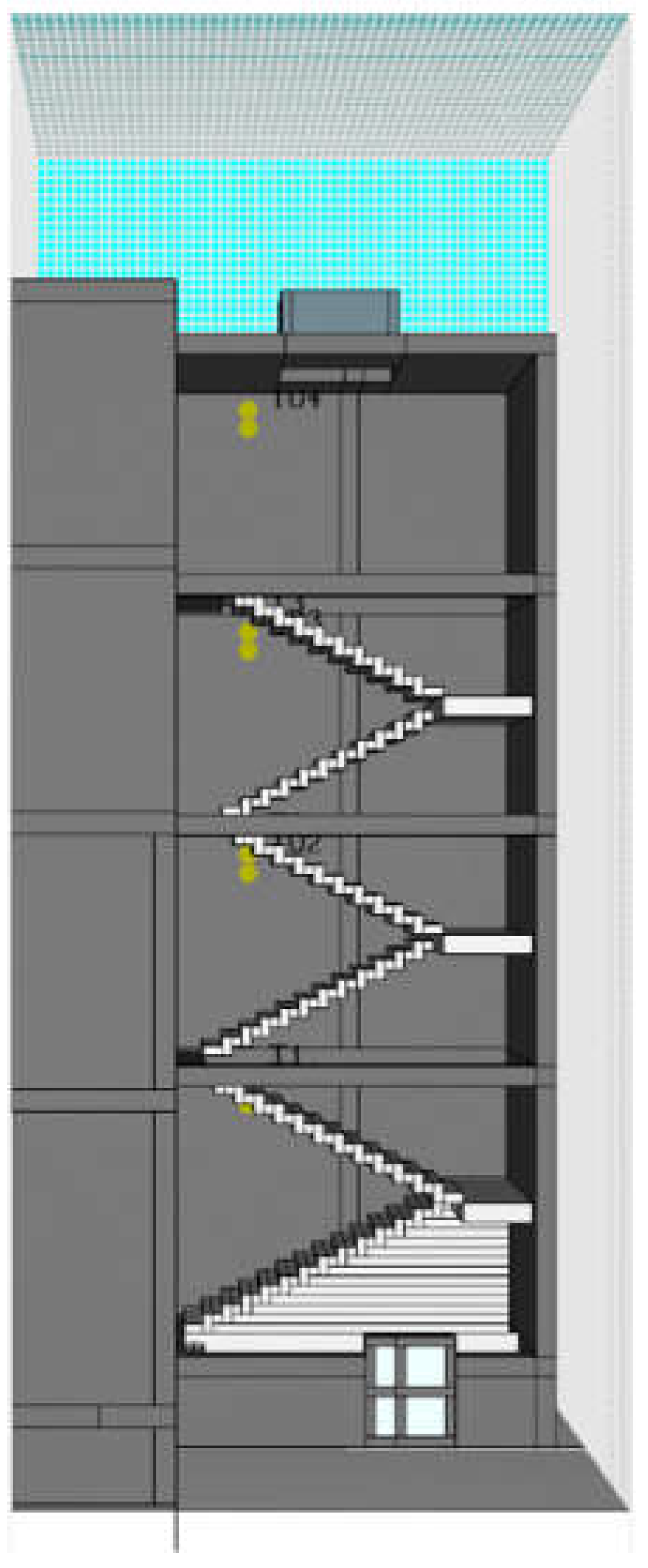
The computational model of the staircase of the LabFactor building is shown in Figure 10.
5.3. Simulation Results
5.3.1. Temperature
Using the 3D computational model of the staircase, a series of airflow simulations was carried out to compare the model’s results with the experimental results. For this purpose, the model used temperature measurement planes at the approximate location of the temperature sensors (Figure 3). The simulations were carried out for the outside air temperatures of −2.0, 15.4, and 35.4 °C, relative to the experimental results presented earlier.
Table 2 presents the results of the CFD simulations for selected outside air temperatures. The pictures use a set of colours corresponding to the air temperature presented on the scales.
As shown on the images in Table 2, in the winter period (Tout = −2.0 °C), the staircase space gradually cools down after opening of the external door. For a higher outside temperature (Tout = 15.4 °C) the nature of the airflow is similar. The warm indoor air rises upwards, leaving the staircase space through the open smoke damper. The greatest variation in internal temperature occurred at approximately 120 (for Tou t = −2.0 °C) and 240 s (for Tout = 15.4 °C) when the incoming outside air reached the upper part of the staircase. Operation of the natural smoke exhaust system causes gradual cooling of the staircase space. In summer (Tout = +35.5 °C), warm outside air flows into the staircase through the open smoke damper and gradually descends downwards. The images presented in Table 2 shows that the nature of the inflow of outside air in winter and summer is different. In winter, the outside air gradually fills the next floors. In the summer, external air flows into the staircase, immediately affecting all floors of the building.
5.3.2. Velocity
Using the same 3D model as previously, the air velocity distribution in the staircase space was verified. The measuring plane was located in the light of the smoke damper, which is the outlet section of the ventilation system. The simulations were carried out for the same outside air temperatures: −2.0, 15.4, and 35.4 °C.
Table 3 presents the results of the velocity distribution of the CFD simulations for selected outside air temperatures. The pictures present a set of colours relative to the air velocity visible in the scale.
As can be seen in Table 3, both in the winter and summer periods, the velocity in the cross-section of the staircase does not exceed 1 m/s.
The highest flow velocity can be observed in the initial period, after opening of the smoke damper. Due to the decrease in the temperature difference between the outside and inside, the air flow speed also decreased. In the second half of the analysed period, the air volume decreased to the value of 0.2 m/s for the winter period (Tout = −2.0 °C) and 0.5 m/s for the summer (Tout = −35.5 °C). It is also seen in the drawings that the main airflow was realised in the immediate vicinity of the stair flights and was limited near walls.
The nature of the airflow through the staircase during the operation of the natural ventilation system, with a limited flow outside the flight of the stairs, allowed to understand the smoke damper dimensioning procedures adopted in CNBOP guidelines [4].
5.4. Air Volume Flowing through the Smoke Damper
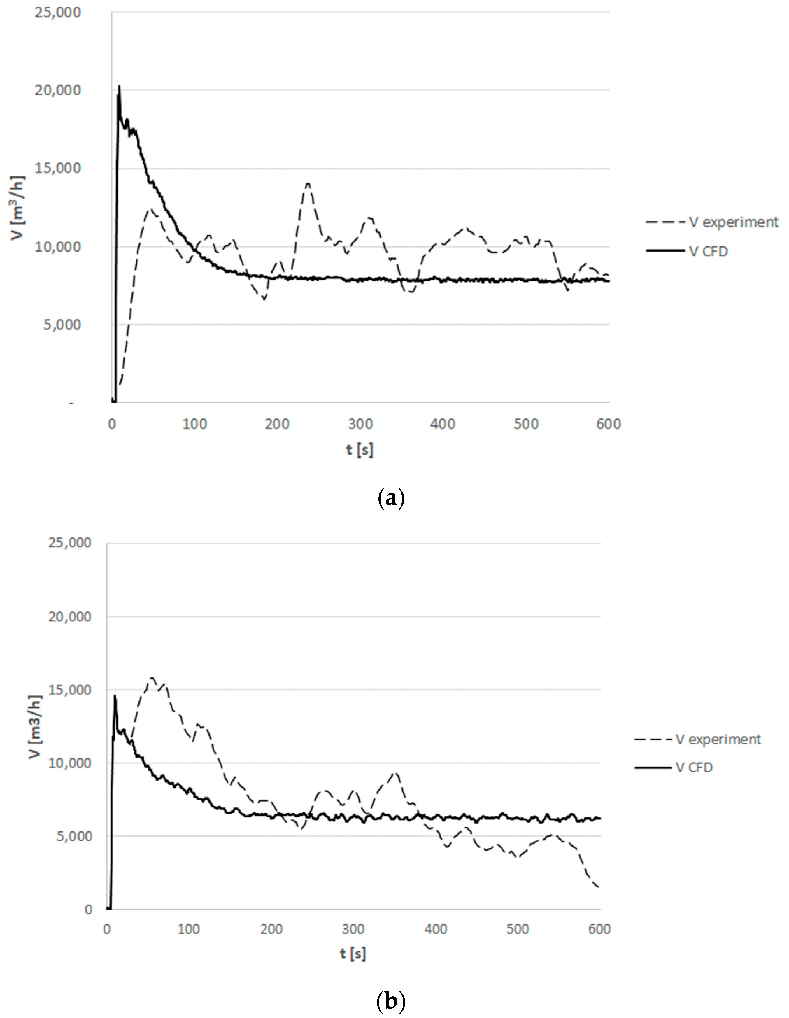
The air volume flowing through the smoke damper based on measurements and CFD simulation results for extreme measured values of outdoor temperature are presented in Figure 11. The experimental data made use of moving averages (step 10 for Tout = −2.0 °C and step 30 for Tout = 35.4 °C).
As can be seen in Figure 11, the temporary fluctuations in the airflow through the smoke damper based on measurement are higher than in the CFD simulation. The differences were caused by a number of simplifying assumptions that were made in the CFD model. For example, there was no allowance for wind and heat radiation, which affect local air turbulence. The difference between average air volume flow obtained during measurement and CFD simulation is within the range of 20%. The high convergence of the obtained results using CFD simulation allows the use CFD simulation programs to verify the potential performance of the natural smoke exhaust system during the year for any staircase geometry.
6. Effectiveness of the Natural Smoke Exhaust System
A series of outdoor air temperature graphs were developed to help determine the operable characteristics of natural smoke exhaust systems throughout the year on the basis of the following data:
- Database of the atmospheric conditions was published by the Ministry of Investments and Development: “Typical meteorological years and statistical climatic data for the area of Poland for energy calculations of buildings” [25]—designation Tout GOV.
- Measured outside temperature values for 2019, measurement carried out by a local meteorological station of Lodz University of Technology—designation Tout 2019.
- Measured outside temperature values for 2020, measurement carried out by a local meteorological station of Lodz University of Technology—designation Tout 2020.
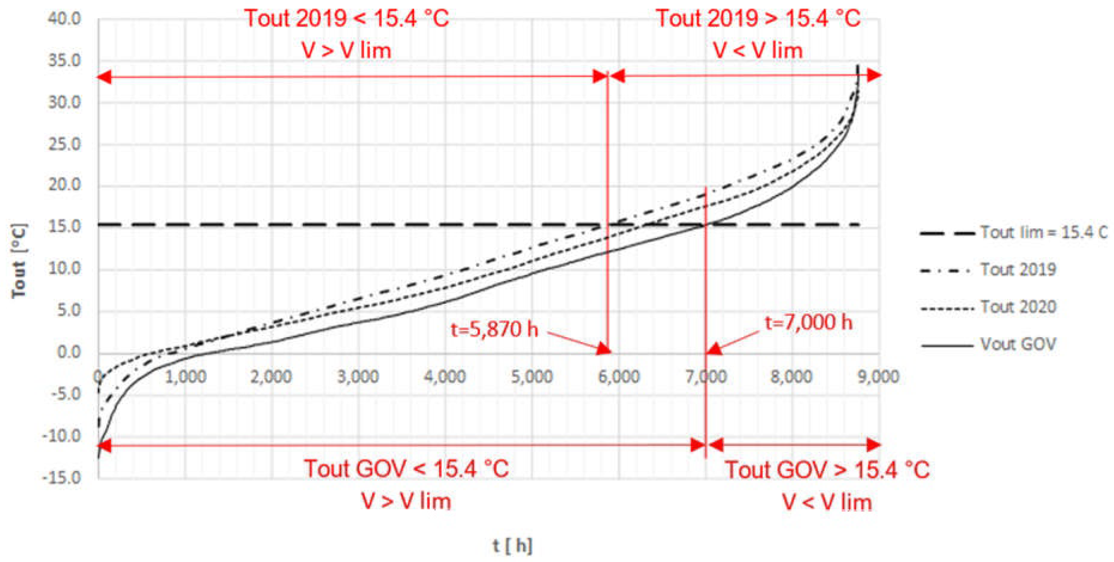
Diagrams of the outside air temperature were prepared on the basis of a long time period of statistical data for Lodz (Tout GOV [25]) and measurements in 2019 (Tout 2019) and 2020 (Tout 2020). Data of temperature variation over the year are presented in Figure 12. The X axis represents the number of hours in the year, while the Y axis represents the outside air temperature values. Based on Figure 12, some similar tendencies of the outside air temperature values in the years 2019 and 2020 and typical meteorological years could be observed.
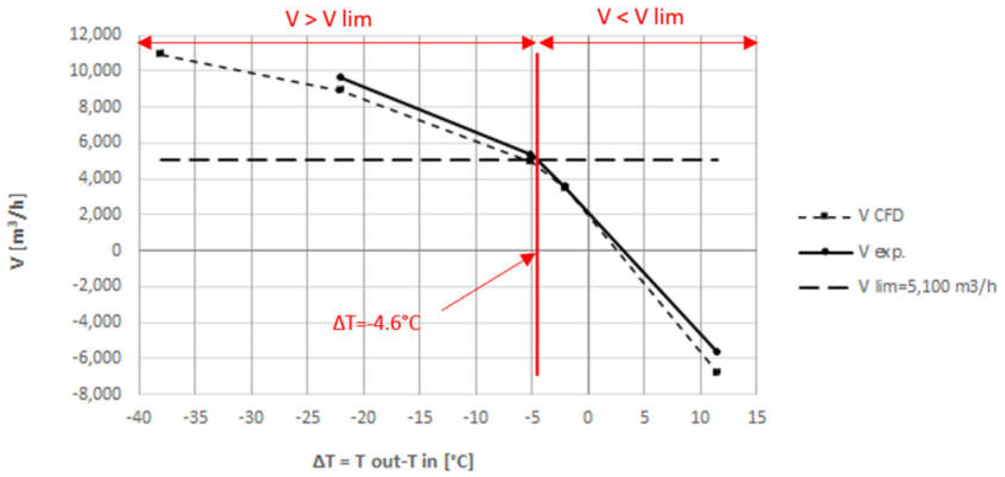
In the next step, the air volume flow through the smoke damper based on temperature difference (between the outside and inside air temperature) was specified. The performance analysis was carried out on the basis of the results obtained during measurements and CFD simulations for several values of outdoor air temperatures. Results are presented in Figure 13.
As identified in Figure 13, the results of CFD simulations confirm the experimental results and their differences did not exceed 20%.
It was assumed that the natural smoke exhaust system can provide for at least 10 times the number of air exchanges per hour [26]. The volume of the analysed staircase was about 510 m3, so the minimal airflow volume for the natural smoke exhaust system was assumed as Vlim = 5100 m3/h. In the experiments, such airflow was reached when the external and internal temperature difference was equal to ΔT = −4.6 °C (Tout−Tin = 15.4−20.0 °C).
Figure 12 provides details for the number of hours in a year for which the outside air temperature is higher than 15.4 °C. The number of hours below the assumed outside temperature (Tout < 15.4 °C) was between 5870 (Tout 2019) and 7000 (Tout GOV), depending on the data source.
When analysing Figure 12, it can be noticed that, during approx. 5870–7000 h per year (67–80%), the outside air temperature was lower than the minimum (Tout lim = 15.4 °C), which means that the natural smoke exhaust system would be operating with the required airflow. Lower outside air temperature (Tout < Tout lim) induces a stronger stack effect.
7. Conclusions
Natural smoke control systems in staircases are commonly used for the protection of escape routes against smoke and are the most popular systems in medium to high rise buildings. Devices used for smoke extraction (door and smoke damper) can also be used for ventilation of the staircase. The proper operation of ventilation and the smoke exhaust system is necessary for removing chemical and thermal pollution generated during ordinary and extraordinary (for example, a fire) use of the staircase.
On the basis of the conducted analysis based on the experimental data and the CFD results, it was concluded that:
- Effectiveness of natural ventilation and the smoke exhaust system is strongly dependent on the weather conditions, especially the temperature external to the building. This was proved experimentally and based on CFD simulations it was found that the airflow through a staircase depends on the outside air temperature,
- The outdoor temperature limit (Tout lim = 15.4 °C) was defined to determine an acceptable level of the system efficiency, assumed as 10 changes per hour. It was found that natural ventilation and smoke exhaust systems could potentially operate below an acceptable level of efficacy for nearly 25% of the year (when the outside air temperature is higher than 15.4 °C).
- CFD simulations allow verification of the ventilation or smoke and heat ventilation system and could be used for verification of any staircase of any building type and its location.
Author Contributions
Conceptualisation, A.B. and D.B.; methodology, A.B. and D.B.; software, A.B.; validation, A.B.; formal analysis, A.B. and D.B.; investigation, A.B. and D.B.; resources, A.B. and D.B.; data curation, A.B.; writing—original draft preparation, A.B.; writing—review and editing, D.B.; visualisation, A.B.; supervision, D.B.; project administration, D.B. All authors have read and agreed to the published version of the manuscript.
Funding
This research received no external funding.
Institutional Review Board Statement
Not applicable.
Informed Consent Statement
Not applicable.
Data Availability Statement
The data that support the findings of this study are available from the corresponding author upon reasonable request.
Conflicts of Interest
The authors declare no conflict of interest.
References
- European Guideline. Smoke and Heat Exhaust Ventilation Systems Planning and Design; CFPA-E No 35:2015 F; CFPA Europe: Chester, UK, 2015. [Google Scholar]
- Polish-Regulation. Regulation of the Minister of Infrastructure on Technical Conditions to be Met by Buildings and Their Location; Ministry of Infrastructure: Warsaw, Poland, 2002.
- Polish Organization for Standardization. Fire Protection of Buildings. Natural Smoke Exhoust Installations for the Extraction of Smoke and Heat. Design Rules; PrPN-B-02877-4; Polish Organization for Standardization: Warsaw, Poland, 2001. [Google Scholar]
- Scientific and Research Centre for Fire Protection—National Research Institute. CNBOP Guidelines: Staircase Smoke Extraction Systems; CNBOP: Józefów, Poland, 2019. [Google Scholar]
- VdS Schadenverhütung GmbH. Staircase Smoke Removal Devices. Design and Installation; VdS 2221:2001-08 (01); VdS: Cologne, Germany, 2001. [Google Scholar]
- Smardz, P. Fire ventilation of staircases in Europe. Fire Prot. 2017, 2, 5–10. [Google Scholar]
- Wnęk, W.; Kubica, P.; Boroń, S.; Burda, M. Analysis of possibility of Using Mechanical Compressory Airflow in Gravitational Smoke Removal Systems from Staircases. Sci. Pap. Main Sch. Fire Serv. 2012, 44, 5–23. [Google Scholar]
- Zhao, G.; Tarek, B.; Bart, M. Study of FDS simulations of buoyant fire-induced smoke movement in a high-rise building stairwell. Fire Saf. J. 2017, 91, 276–283. [Google Scholar] [CrossRef]
- Shi, W.X.; Ji, J.; Sun, J.; Lo, S.M.; Li, L.J.; Yuan, X. Influence of fire power and window position on smoke movement mechanisms and temperature distribution in an emergency staircase. Energy Build. 2014, 79, 132–142. [Google Scholar] [CrossRef]
- Lim, H.; Seo, J.; Song, D.; Yoon, S.; Kim, J. Interaction analysis of countermeasures for the stack effect in a high-rise office building. Build. Environ. 2020, 168, 106530. [Google Scholar] [CrossRef]
- Kubicki, G.; Cisek, M. How to Protect Staircases in Case of Fire in Mid-Rise Buildings. Real Scale Fire Tests. Saf. Fire Technol. 2019, 54, 6–20. [Google Scholar] [CrossRef]
- Qin, T.X.; Guo, Y.C.; Chan, C.K.; Lau, K.S.; Lin, W.Y. Numerical simulation of fire-induced flow through a stairwell. Build. Environ. 2005, 40, 183–194. [Google Scholar] [CrossRef]
- Khoukhi, M.; Yoshino, H.; Liu, J. The effect of the wind speed velocity on the stack pressure in medium-rise buildings in cold region of China. Build. Environ. 2007, 42, 1081–1088. [Google Scholar] [CrossRef]
- Peppes, A.; Santamouris, M.; Asimakopoulos, D. Buoyancy-driven flow through a stairwell. Build. Environ. 2001, 36, 167–180. [Google Scholar] [CrossRef]
- Skaźnik, M. Devices to remove smoke from the space of staircases. Fire Prot. 2011, 12, 15–21. [Google Scholar]
- Li, L.J.; Ji, J.; Fan, C.G.; Sun, J.; Yuan, X.; Shi, W.X. Experimental investigation on the characteristics of buoyant plume movement in a stairwell with multiple openings. Energy Build. 2014, 68, 108–120. [Google Scholar] [CrossRef]
- Chow, W.K.; Li, J. Wind Effects on Performance of Static Smoke Exhaust Systems: Horizontal Ceiling Vents. ASHRAE Trans. 2014, 110, 479–488. [Google Scholar]
- Chen, J.; Wang, J.; Wang, B.; Liu, R.; Wang, Q. An experimental study of visibility effect on evacuation speed on stairs. Fire Saf. J. 2018, 96, 189–202. [Google Scholar] [CrossRef]
- PolishStandard. Smoke and Heat Control Systems—Part 6: Technical Requirements for Pressure Differential Systems—Equipment Set; PN EN 12101-6; Polish Standard: Warsaw, Poland, 2007.
- Wróblewski, D.B.; Guzewski, P.; Małozięć, D. Red Book of Fires Volume 2; CNBOP: Józefów, Poland, 2016; Available online: https://www.cnbop.pl/wydawnictwa/ksiazki/978-83-61520-87-0/ckp_2016_t2_001-592_www.pdf (accessed on 1 November 2021).
- Wróblewski, D.B.; Guzewski, P.; Małozięć, D. Red Book of Fires Volume 1; CNBOP: Józefów, Poland, 2016; Available online: https://www.cnbop.pl/wydawnictwa/ksiazki/978-83-61520-83-2/ckp_2016_t1_001-624.pdf (accessed on 1 November 2021).
- Mizieliński, B.; Kubicki, G. Fire Ventilation. Smoke Exhaust; Wydawnictwo WNT: Warsaw, Poland, 2012. [Google Scholar]
- Google Map of Lodz, Poland. Available online: https://www.google.com/maps/@51.7552277,19.4535358,17.79z?hl=pl (accessed on 1 November 2021).
- COMSOL Multiphysics. Femlab 3—User’s Guide; COMSOL: Stockholm, Sweden, 2004. [Google Scholar]
- Typical Meteorological Years and Statistical Data Collected for Polish Energy Stations for Energy Measurements. Available online: https://dane.gov.pl/pl/dataset/797,typowe-lata-meteorologiczne-i-statystyczne-dane-klimatyczne-dla-obszaru-polski-do-obliczen-energetycznych-budynkow (accessed on 1 November 2021).
- British Standards Institution. Components for Smoke and Heat Control Systems—Code of Practice on Functional Recommendations and Calculation Methods for Smoke and Heat Control Systems for Covered Car Parks; BS 7346-7:2013; BSI: London, UK, 2013. [Google Scholar]
Figure 1.
Solutions of smoke and heat ventilation systems for a staircase.

Figure 2.
Normal and reverse stack effects.

Figure 3.
A diagram of the measuring station in the tested staircase (all dimensions shown in the drawing are specified in centimetres).
Figure 3.
A diagram of the measuring station in the tested staircase (all dimensions shown in the drawing are specified in centimetres).

Figure 4.
Measuring device for external air conditions.

Figure 5.
Map showing the LabFactor building and A6 building on the Campus of Lodz University of Technology (Source: [23]).
Figure 5.
Map showing the LabFactor building and A6 building on the Campus of Lodz University of Technology (Source: [23]).

Figure 6.
Flow around an asymmetrical smoke damper without wind (FEMLAB own study). On the x and y axes, the dimensions (in meters) of the staircase are shown.
Figure 6.
Flow around an asymmetrical smoke damper without wind (FEMLAB own study). On the x and y axes, the dimensions (in meters) of the staircase are shown.

Figure 7.
The free convectional airflow (the stack effect) simulation in the space of the staircase (FEMLAB own study). On the x and y axes, the dimensions (in meters) of the staircase are marked.
Figure 7.
The free convectional airflow (the stack effect) simulation in the space of the staircase (FEMLAB own study). On the x and y axes, the dimensions (in meters) of the staircase are marked.

Figure 8.
The air temperature in the staircase in the representative experiments (a) in winter (23 February 2019) and (b) in summer (30 June 2019).
Figure 8.
The air temperature in the staircase in the representative experiments (a) in winter (23 February 2019) and (b) in summer (30 June 2019).


Figure 9.
The air volume flowing through the smoke damper based on measurements for several values of outdoor temperature (a) −2.0 °C, (b) 15.6 °C, and (c) 35.4 °C.
Figure 9.
The air volume flowing through the smoke damper based on measurements for several values of outdoor temperature (a) −2.0 °C, (b) 15.6 °C, and (c) 35.4 °C.


Figure 10.
LabFactor K2 staircase model.

Figure 11.
The air volume flowing through the smoke damper based on measurements and CFD simulation results for extreme values of outdoor temperature. (a) Tout = −2.0 °C and (b) Tout = 35.4 °C.
Figure 11.
The air volume flowing through the smoke damper based on measurements and CFD simulation results for extreme values of outdoor temperature. (a) Tout = −2.0 °C and (b) Tout = 35.4 °C.

Figure 12.
Line graph of measurements outdoor air temperature for Lodz based on the government database and measurements.
Figure 12.
Line graph of measurements outdoor air temperature for Lodz based on the government database and measurements.

Figure 13.
Air volume flow through the smoke damper for several temperature variances.


Table 1.
Mesh size analysis.
| Grid Cell Size | |||||
|---|---|---|---|---|---|
| 0.36 × 0.36 × 0.36 (m) | 0.24 × 0.24 × 0.24 (m) | 0.18 × 0.18 × 0.18 (m) | 0.09 × 0.09 × 0.09 (m) | ||
| Number of cells in the mesh | 46,200 | 155,232 | 369,600 | 2,956,800 | |
| Calculation time (min) | 35 | 150 | 1080 | 5420 | |
| Air temperature distribution in 15 s |  |  |  |  |  |
| Air temperature distribution in 60 s |  |  |  |  | |
Table 2.
Variation in air temperature in the staircase space depending on the outside temperature.
| Time (s) | Simulations Results | ||||
|---|---|---|---|---|---|
| Tout = −2.0 °C | Tout = 15.4 °C | Legend (°C) | Tout = 35.5 °C | Legend (°C) | |
| 0 |  |  |  |  |  |
| 60 |  |  |  | ||
| 120 |  |  |  | ||
| 240 |  |  |  | ||
| 600 |  |  |  | ||
Table 3.
Variation in air velocity in the staircase space depending on the outside temperature.
| Time (s) | Simulations Results | |||
|---|---|---|---|---|
| Tout = −2.0 °C | Tout = 15.4 °C | Tout = 35.5 °C | Legend (m/s) | |
| 15 |  |  |  |  |
| 30 |  |  |  | |
| 60 |  |  |  | |
| 120 |  |  |  | |
| 240 |  |  |  | |
| 600 |  |  |  | |
Publisher’s Note: MDPI stays neutral with regard to jurisdictional claims in published maps and institutional affiliations. |
© 2022 by the authors. Licensee MDPI, Basel, Switzerland. This article is an open access article distributed under the terms and conditions of the Creative Commons Attribution (CC BY) license (https://creativecommons.org/licenses/by/4.0/).
Share and Cite
MDPI and ACS Style
Bogusławska, A.; Brzezińska, D. The Impact of Outdoor Temperatures on the Efficacy of Natural Ventilation and Smoke Exhaust Systems. Energies 2022, 15, 933. https://doi.org/10.3390/en15030933
AMA Style
Bogusławska A, Brzezińska D. The Impact of Outdoor Temperatures on the Efficacy of Natural Ventilation and Smoke Exhaust Systems. Energies. 2022; 15(3):933. https://doi.org/10.3390/en15030933
Chicago/Turabian StyleBogusławska, Arleta, and Dorota Brzezińska. 2022. "The Impact of Outdoor Temperatures on the Efficacy of Natural Ventilation and Smoke Exhaust Systems" Energies 15, no. 3: 933. https://doi.org/10.3390/en15030933
Note that from the first issue of 2016, this journal uses article numbers instead of page numbers. See further details here.