Review

A Review of Fuel Cell Powertrains for Long-Haul Heavy-Duty Vehicles: Technology, Hydrogen, Energy and Thermal Management Solutions

1
ETEC Department & MOBI-EPOWERS Research Group, Vrije Universiteit Brussel (VUB), Pleinlaan 2, 1050 Brussel, Belgium
2
Flanders Make, Gaston Geenslaan 8, 3001 Heverlee, Belgium
3
Nederlandse Organisatie voor Toegepast-Natuurwetenschappelijk Onderzoek TNO, Automotive Campus 30, 5708 JZ Helmond, The Netherlands
*
Author to whom correspondence should be addressed.
Energies 2022, 15(24), 9557; https://doi.org/10.3390/en15249557
Submission received: 24 October 2022 / Revised: 24 November 2022 / Accepted: 3 December 2022 / Published: 16 December 2022
(This article belongs to the Section E: Electric Vehicles)

Abstract

:
Long-haul heavy-duty vehicles, including trucks and coaches, contribute to a substantial portion of the modern-day European carbon footprint and pose a major challenge in emissions reduction due to their energy-intensive usage. Depending on the hydrogen fuel source, the use of fuel cell electric vehicles (FCEV) for long-haul applications has shown significant potential in reducing road freight CO 2 emissions until the possible maturity of future long-distance battery-electric mobility. Fuel cell heavy-duty (HD) propulsion presents some specific characteristics, advantages and operating constraints, along with the notable possibility of gains in powertrain efficiency and usability through improved system design and intelligent onboard energy and thermal management. This paper provides an overview of the FCEV powertrain topology suited for long-haul HD applications, their operating limitations, cooling requirements, waste heat recovery techniques, state-of-the-art in powertrain control, energy and thermal management strategies and over-the-air route data based predictive powertrain management including V2X connectivity. A case study simulation analysis of an HD 40-tonne FCEV truck is also presented, focusing on the comparison of powertrain losses and energy expenditures in different subsystems while running on VECTO Regional delivery and Longhaul cycles. The importance of hydrogen fuel production pathways, onboard storage approaches, refuelling and safety standards, and fleet management is also discussed. Through a comprehensive review of the H 2 fuel cell powertrain technology, intelligent energy management, thermal management requirements and strategies, and challenges in hydrogen production, storage and refuelling, this article aims at helping stakeholders in the promotion and integration of H 2 FCEV technology towards road freight decarbonisation.

1. Introduction

With the ever-increasing impact of greenhouse gas (GHG) emissions on global warming, the importance of using low-emission transport technologies is gaining momentum all over the world. The growing population in big cities and rising usage of fossil-fuelled vehicles is today a major source of local air pollution and an alarming concern for public health [1]. In Europe, heavy-duty vehicles (HDVs) emit around 25% of its total CO 2 emissions from road transport, contributing to about 5% of all GHG emissions and posing a significant challenge in pollution reduction due to the nature of their usage [2,3,4]. Among other applications, long-haul trucks take up about 65–70% of these emissions and are of premier focus in the EU carbon footprint reduction plans for meeting the goals of the Paris Agreement [5,6]. With the aim at 90% net emissions curtailment by 2050, the EU has established CO 2 Emission Standards Regulation ((EU) 2019/1242) for new heavy-duty (HD) trucks targeted at a 15% fleet-wide reduction by 2025 and 30% by 2030 against 2019–2020 baseline [2,5]. According to a recent McKinsey report on road freight global pathways, medium and heavy-duty road transport accounts for about half of the global trade-related transport carbon footprint and approximately 15% of the total European CO 2 emissions, out of which 70% come from HD trucks [7]. The International Energy Agency (IEA) further expects global CO 2 emissions from HDVs to increase by 14.8% by 2030 [8].

1.1. Hydrogen and Battery Electric Propulsion for Long-Haul Decarbonisation

Amid the various upcoming technologies for achieving freight carbon neutrality, electrification of HDVs is gaining high importance with the possibility of avoiding in-city local air pollution through the implementation of zero urban emission zones (ZUEZ) and decreasing or even eliminating tailpipe CO 2 emissions over long-haul applications using highly-electrified plug-in solutions (PHEVs and BEVs) [9,10,11,12,13,14]. However, the adaptation of battery-electric propulsion for long-haul applications is currently hindered by various technical and practical constraints such as limited vehicle range and long charging time affecting delivery schedules and vehicle up-time, economic and environmental costs of battery production, increased vehicle size and reduced payload capacity from a rise in tractor weight hampering its economic feasibility for the commercial market [15,16]. Verbruggen et al. have shown a minimum reduction in cargo capacity of approximately 4 tonnes for a long-haul 40-tonne truck considering a range of 600 km, battery pack energy density of 150 Wh/kg and an average energy consumption of 1.72 kWh/km [17]. In contrast, a typical HD fuel cell electric vehicle (FCEV) could reach a range of 800 km using a single fuelling session with two hydrogen tanks carrying 40–60 kg of hydrogen, each stored at 350 bars [18]. The main advantage of the fuel cell system over electrochemical batteries can be linked to the separation of power generation and onboard energy storage that facilitates improvements in both these aspects while minimising their interdependencies [1,19]. H 2 FCEVs offer a good alternative over battery electric vehicles (BEVs) for long-haul propulsion with fast refuelling, lower infrastructure requirement, reduced powertrain weight facilitating increased payload capacity, corresponding economic benefits and practicability while still achieving zero tailpipe emissions and could thus prove as a more favourable pathway to decarbonisation and electrification of the HD transport sector even with lower overall tank-to-wheel (TTW) conversion efficiencies [20,21,22,23,24,25].

1.2. Fuel Cells over Combustion Engines for Hydrogen Mobility

Among other modes of using H 2 fuel for heavy-duty propulsion, onboard fuel cell systems (FCS) and traditional internal combustion engines (ICE) have currently been proven as the most viable solutions [26,27]. When comparing the two, FCS have the advantage of the higher overall TTW efficiency, zero tailpipe emissions (NO x ) and reduced operating noise, making them the preferred choice for future HD hydrogen mobility [28,29]. At the same time, ICE applications profit from lower manufacturing and implementation costs due to existing production infrastructure, minimal utilisation of precious metals, the possibility of retrofitting, no necessity of electrification, low sensitivity to hydrogen fuel purity, and could act as a transition technology to promote H 2 fuel production and future freight decarbonisation [27,30].

1.3. Renewable Hydrogen towards Sustainability

Hydrogen for propulsion can be produced from various sources with different carbon footprints and cost competitiveness [27]. When electricity is directly used to produce hydrogen through electrolysis, the environmental impact highly depends on the grid energy source [30]. H 2 fuel cell propulsion can also improve the practicability of intermittent renewable energy in road transport through hydrogen usage as both a fuel and a transferable vehicle-to-grid (V2G) energy buffer, further supporting decentralised renewable electricity generation similar to battery energy storage without their production and economic impacts [31,32,33,34]. Hydrogen is currently produced mainly from fossil fuels as feedstock through natural gas reforming or coal gasification at the expense of higher life-cycle GHG emissions. The promotion of renewable electricity and techniques such as carbon capture could be used to lower this carbon footprint by up to 90% [35,36]. Lee et al. have compared life cycle implications of H 2 FCEV and diesel ICE propulsion for medium and heavy-duty applications in the United States and have shown GHG emission lowering of 20–45% along with significant reductions in CO, NO x , PM emissions depending on the source of H 2 production [37].

1.4. Challenges in H 2 Refuelling

One of the main challenges for the uptake of hydrogen-based vehicles is the extended availability of refuelling infrastructure [38]. In contrast to BEV, which may operate only on a regional delivery or distribution logical pattern, long-haul applications require that the infrastructure is widely dispersed (for Europe, mainly along the TEN-T corridors). Within the Fit for 55 legislation package, a revised version of the Alternative Fuels Infrastructure Directive, named AFIR [39], has outlined requirements for infrastructure [40]. Similar provisions are also being made in North America [41]. The representative body for the EU OEMs, ACEA, takes the position that new technologies such as battery-electric and fuel cell can only be enabled if member states support a minimum set of infrastructure [42]. ACEA projects a requirement for 300 hydrogen refuelling stations by 2025, and 1000 by 2030, to serve heavy-duty transport needs [43]. Such stations would be expected to dispense six tonnes of hydrogen daily, with at least one refuelling station every 200 km. Alongside public infrastructure, private or co-owned infrastructure could facilitate the earlier adoption of FCEVs in some logistics operations. However, given the high costs of such refuelling stations, this is anticipated to be in the minority.

1.5. HD Fuel Cell Vehicle Total Cost of Ownership

Recent analysis from the Swedish Electromobility Center has shown that for countries like Germany, the total cost of ownership (TCO) among alternative long-haul powertrain applications primarily depends on the fuel and battery expenditure and can be lower for FCEV powertrains than BEV applications. For city and regional transportation, the TCO of FCEV propulsion could be even lower than that for traditional ICE propulsion depending on H 2 fuel incentives [44,45]. The National Renewable Energy Laboratory report focused on ownership costs using actual business models has shown a substantial decrease in the purchase price and TCO of fuel cell powertrains for commercial vehicles by 2025 with the possibility of achieving price parity of zero-emission technologies with diesel applications. The study has indicated that both FCEV and BEV zero emission technologies could complement each other on the path to decarbonisation with their respective long-range and high-efficiency advantages [46]. Through a detailed 2017 baseline automotive cost analysis, Thompson et al. have further suggested that FCS cost accounts for a significant part of the total FCEV powertrain expenditure, with bipolar plates and catalyst materials accounting for a major portion [47]. Marcinkoski et al. have shown no major technical hurdles in the current adaptation of H 2 fuel cell powertrain technology against conventional diesel heavy-duty applications. They have suggested that significant challenges could come from the cost and durability of FCS, which could be resolved through economies of scale and future transitions of the market [48,49]. A fact-based EU-supported independent study on TCO of FC hydrogen trucks by Fuel Cells and Hydrogen Joint Undertaking (FCH) has shown significant cost-down potential and clear economic competitiveness of FCEV over diesel-based powertrains by 2027 if production volumes are increased swiftly and H 2 costs are lowered below 6 euro/kg. At this rate, the study approximates 17% HD FCEV sales share by the year 2030, even if current FC trucks have been found to cost a premium of up to 22% over diesel applications [2].

1.6. Future Trends in Long-Haul H 2 Fuel Cell Mobility

Several HD original equipment manufacturers (OEMs) listed in Section 2 are already pushing for the development and market implementation of FCEV platforms for bridging the gap toward economic feasibility of fuel cell electric propulsion and future sustainable mobility [50,51]. The US Department Of Energy (DOE) Office of Transportation released performance targets in 2019 for future H 2 long-haul trucks aimed at technology competitiveness by 2030 through 2050. The performance targets covered vehicle level down to powertrain subsystems, fuel cell components, H 2 storage and refuelling infrastructure. By 2030 towards 2050, FCS lifetime is expected to reach from 25,000 h towards 30,000 h, cost from 80 $/kW to 60 $/kW, peak efficiency from 68% to 72%, H 2 fuelling rate 8 kg/min towards 10 kg/min and H 2 storage cost 300 $/kg towards 266 $/kg [52]. A recent report by Fuel Cells and Hydrogen Joint Undertaking noted HD FCEV product development, performance and systems integration, FCS stack lifetime, H 2 storage weight–volume limitation, refuelling networks, standardised fuelling protocols, capital and operating expenditure, financing and funding support, and long-term plannability as the main barriers in widespread adoption of fuel cell technology [2]. They identified multimodal fuel cell technology synergies across the transport sector as the key factor in successful HD sector commercialisation through advantages such as decreasing production costs, transferred experience, optimised H 2 production, fuelling infrastructure utilisation and improved demand for renewable hydrogen.
The current work aims at providing a detailed review of the HD H 2 fuel cell electric propulsion technology suited for future decarbonisation of the long-haul vehicle sector. The rest of this article is organized into several sections: Section 2 presents current examples of HD FCEV applications and compares them with service and light commercial vehicle examples. Section 3 describes FCEV powertrain topology suited for long-haul applications, including discussion on electric traction drives, DC link power converters, energy storage systems, HD auxiliary loads, H 2 fuel storage and fuel cell system. To obtain a better understanding of fuel cell powertrain system level operation, a case study for an HD 40-tonne FCEV truck running on VECTO Regional delivery and Longhaul cycles has been simulated and compared in Section 3.2 with a focus on the energetic analysis of losses, energy expenditures and power flow across different subsystems. Balance of plant components, proton exchange membrane fuel cell operation and fuel cell ageing, are further explained in Section 3.3, Section 3.4 and Section 3.5 to realise the working principles and constraints of the H 2 fuel cell technology. A review of subsystems control challenges, multi-layer energy management strategies and scope of V2X connectivity-based predictions in further improving vehicle efficiency are discussed in Section 4. Thermal management challenges specific to FCS and other powertrain subsystems, including sub-zero cold start strategies and cooling requirements, have been detailed in Section 5, along with possible intelligent control and energy-saving strategies. This is followed by an overview of H 2 refuelling infrastructure and safety standards, fuel production pathways, environmental impact and fleet management for HD long-haul FCEV applications (Section 6 and Section 7). Finally, the main conclusions of this review article have been summarized in the last section.

2. FCEV Heavy-Duty Applications

Depending on the expected usage of the vehicle, the FCEV powertrain could be implemented in various ways by changing the size, and proportion of the fuel cell system prime mover and energy storage system (hybridisation factor) for fulfilling the power requirement [1,53]. In the case of light commercial vehicles (LCV) and last-mile delivery applications, plug-in FCEV with a small FCS range extender could be a choice favouring the usage of direct plug-in electricity for regular commute and hydrogen propulsion for occasional long-distance journeys, as considered by the Renault Group for its Maxity H 2 service vehicle, Master ZE H 2 and Kangoo ZE H 2 vehicles (20 kW FCS, 5 kg H 2 , 42 kWh battery and 5 kW FC, 1.78 kg H 2 , 33 kWh battery, respectively) [1,54]. On the other hand, a mid-power fuel cell powertrain concept including plug-in battery charging capability is being considered by Stellantis for LCV applications (45 kW FC, 4.4 kg H 2 and 10.5 kWh battery) with advantages in packaging, actual usable highway range and also electric-only operation on shorter journeys for minimising H 2 economic and environmental impact or in lack of refuelling infrastructure [55].
For medium and heavy-duty long-haul applications, the industry seems to favour a full-power hybridisation factor, with the H 2 FCS taking the primary responsibility of covering traction and auxiliary power requirements while the ESS (usually an electrochemical battery pack or supercapacitor) is used under cold start, very low load, boosting, load levelling, during transient operations for maintaining high FCS efficiency (Section 3.3) and for storing and reusing recuperated energy from regenerative braking. Thus, a much smaller ESS size than HD plug-in HEVs and BEVs is chosen for such applications to lower related costs and weight for maintaining good payload capacity, as seen in the H2-Share and H2Haul project demonstrators [56,57,58]. Plug-in battery charging and FCS range extender type operation as seen in the GIANTLEAP project, other city bus examples [59,60,61], the ZECT project [62,63] and a larger ESS battery size for geologically focused trips as seen in REVIVE project garbage truck demonstrators [64,65] is uncommon for long-haul due to the nature of the long-distance freight application for minimising vehicle costs and battery weight. A small FCS range extender could be a good option for HD medium-range BEV applications to cover most journeys using grid electricity while also being capable of occasional long-distance missions [66].
Table 1 lists some of the market-launched and upcoming HD FCEV truck, coach and city bus use cases [67]. With propulsion solely supported by the electric drive, an optimised size is dependent on maximising traction efficiency and on the scope and trend of possible regenerative braking events in the intended driving profile as shown in the LONGRUN project [68]. With its major contribution to powertrain losses, the FCS is usually sized to efficiently satisfy just above the average power requirements of the vehicle while assuring high operating efficiency. Given the drop in FCS efficiency (Section 3.3), the high power requirements (boosting) are thus covered by implementing a slightly larger battery pack with higher current and energy capacity than those seen in modern-day HD hybrid powertrain concepts. Such a sizing preference of the industry can also be reasoned considering the technology maturity, costs of key powertrain components, and the FCS efficiency curve suited for low-mid load range operation. If the powertrain sizing objective is to minimise environmental impact while improving economic feasibility, a sole focus on FCEV H 2 fuel efficiency may not be the best approach considering the importance of different hydrogen production pathways (well-to-tank impact) and components production impact on lifetime CO 2 emissions and costs [68]. To promote the adoption of fuel cell technology in the European heavy-duty sector, the STASHH project funded by Fuel Cells and Hydrogen 2 Joint Undertaking will develop an open standard for sizing, interfacing, controls and testing protocols of fuel cell modules towards lowering TCO, market entry threshold while promoting mass production and reliability [69].

3. FCEV Powertrain

3.1. Powertrain Topology

Generic fuel cell electric vehicle (FCEV) powertrain topologies suited for long-haul heavy-duty applications have been shown in Figure 1. Subsystems and power electronics DC/DC converters are added or removed depending on the nature of the application, expected duty cycle and lifespan, selected onboard energy management and control strategies, product design and cost constraints.

3.1.1. eDrive and Transmission

Similar to commercial BEVs, the fuel cell powertrain is also propelled by one or more electric drives (eDrive) comprising an electric machine (EM) with an inverter feeding alternating electrical energy and controlling motor torque output. For medium and heavy-duty applications, a multi-speed transmission is preferred over single-gear reduction to satisfy the weight-critical vehicle key performance requirements of high gradeability, acceleration and speed while maintaining economic feasibility [98,99]. Using multiple gear reductions can also help with efficient operation and down/right-sizing of the electric drive, thereby reducing cost, weight, energy consumption, cooling requirements, and overall environmental impact of the powertrain [99,100]. Verbruggen et al. have shown the advantage of using a tandem combination of two identical or differently sized eDrives while aiming for better overall traction efficiency [100]. The electric drive is not only responsible for providing traction efforts, but can also recuperate kinetic and potential energy of the moving vehicle during braking and down-hill descends, which can be particularly beneficial for the HDVs due to the combination of heavy weight, highway speeds, mountainous or interurban transient driving conditions and should be taken into account for the right sizing of the eDrive [68,101]. Hub-mounted eDrives can simplify drivetrain packaging while adding modularity for changing applications using planetary gear sets with multi-speed reductions. The main advantage of the hub motor is space-saving, although the limited regenerative braking capability due to size constraints and drawbacks in vehicle dynamics and costs are seen from the increased un-sprung vehicle mass [102]. Under trailer mounted separate e-Dolly concept with dedicated ESS has been introduced in the AEROFLEX project aimed at improving not only overall powertrain efficiency (i.e., enhanced traction, energy storage and regenerative braking), but also saving tractor usage time and improving fleet management through autonomous parking of the trailers at depots [103].
Induction machines (IM) and permanent magnet synchronous machines (PMSM) have been found to be the most preferred electric machine types for modern-day road vehicle applications. They are more favourable than field wound, switch reluctance machines (SRM) and variable flux synchronous machines due to better torque density and efficiency characteristics [104,105]. SRM has the advantages of simpler configuration, absence of permanent magnets, lower costs, high-speed operability, and greater reliability [106]. Brushless DC PMSM offers high efficiency of PMSM along with high-speed operation comparable to SRM machines [106]. Gundogdu et al. have compared torque capabilities, flux weakening, operating efficiency and torque ripple of internal permanent magnet machine (IPM) with conventional and advanced non-overlapping winding induction machines (CIM, AIM) and have shown higher overall efficiency of IPM over the latter (>1%); greater efficiency of AIM over CIM in deep flux-weakening regions along with higher torque ripple; and shorter axial length of AIM with similar efficiency and torque output as CIM, which can further be improved by extending the stack length [104]. To lower dependency on rare-earth materials, permanent magnet-assisted synchronous reluctance machines (PMASRM) are also being considered using less rare-earth permanent magnets for excitation, lowering costs with minimal compromise on torque, high-speed operation, improved reliability, and overall performance [107].

3.1.2. Power Sources

In an HD FCEV, the power for propulsion and auxiliary loads may be supplied solely by the fuel cell system (FCS) (further described in Section 3.3 and Section 3.4) or a combination of FCS and one or more onboard energy storage systems (ESS, e.g., electrochemical battery, supercapacitor, flywheel), to support overall efficient powertrain as well as FCS functioning, response, drivability, good cold start characteristics, operation under extreme scenarios and FCS-ESS lifetime extension depending on the nature of usage (Figure 1) [108]. Aiming for fuel savings and longevity, the trend in modern-day electrified heavy-duty (HD) applications has been to run the complete HV electrical system around 650 or higher voltage levels to support the efficient operation of different subsystems under high power demands [109]. For long-haul applications, the FCS is generally sized as the primary power source and converts chemical energy stored in the onboard hydrogen fuel along with oxygen from the ambient air into DC electrical power for running the traction and auxiliary loads through the DC bus link [110]. The presence of a secondary ESS can be important for such applications to optimise the functioning of the FCS and the energy management of the complete vehicle through the efficient collective operation of different subsystems, as shown in Section 3.2. Even though supercapacitors and flywheel systems offer higher specific power and could efficiently support transient high load demands, electrochemical batteries are currently the most preferred ESS solution due to their suitability for matching HDV specific power, energy, robustness, response and costs requirements (Figure 2) [111,112]. Among other electrochemical battery technologies such as lead-acid, nickel-cadmium (NiCd), nickel metal hydride (NiMH), and sodium–nickel–chloride zebra (NaNiCl), Li-ion cells offer the highest performance and widest choice of specific power to specific energy balance and are the current preference from a price-performance perspective (Figure 2) [113]. For applications with the plug-in electric-only operation, an onboard charger can also be included for directly charging the battery in case of an external alternating current grid supply or for stepping down and controlling battery charging voltage from external direct current supply (Figure 1) [62,63].

3.1.3. DC Link and Converter Combinations

The different power sources (e.g., FCS, HV battery, SC, onboard charger) and loads (e.g., eDrive, LV auxiliaries, power take-off) are usually interconnected through a common high voltage (HV) DC bus whose voltage level is regulated to conduct efficient power generation, traction, charging, braking energy recuperation, reuse and auxiliary load operation while following various energy management strategies (Figure 1) [117]. High power output and efficient operation of the eDrive can be assured by maintaining a constant desired level of DC bus voltage supply to the eDrive (350 V–800 V for HD) [109,118]. Regulating DC bus voltage in plug-in charging can also precisely control the C-rate and corresponding charging power to the HV battery, extending its lifetime. A combination of various DC/DC converter configurations between power sources (e.g., FCS, HV battery and SC), loads (e.g., eDrive, auxiliaries) and the DC bus are generally used to achieve such a degree of freedom over bus voltage regulation supporting desired subsystem operations and powertrain control strategies at the expense of added power electronics converter costs, as seen in Figure 1 [108,119,120]. On the other hand, if there is no DC-DC conversion between the power sources (FCS, ESS) and the eDrive, the electrical motor efficiency can be severely affected during high load demands or low SoC due to field weakening from lowered DC bus voltage. Besides, in the absence of a DC-DC converter in such situations, even adjusting phase current magnitude is unable to fulfil the requirements on eDrive torque and power during high-speed operation and cannot operate at the maximum constant power curve. Therefore, at higher rpm, there is a sharp rise in motor and inverter losses in the eDrive in the absence of DC-DC conversion [121].
With the FCS being an irreversible energy source operating at a largely varying load-dependent terminal voltage and generally being assembled for slightly lower stack voltage level due to mechanical construction limitations, a uni-directional HV DC/DC boost converter is used to interface it with the DC bus [1,122]. In [123], several competitive topologies for FCS DC voltage conversion have been analysed and reviewed. It has been found that the multi-phase interleaved boost converter is suitable for automotive DC bus applications up to 800 V among different non-isolated DC/DC converter topologies due to their capability to (a) provide controlled DC bus voltage with reduced FC stack current ripple to avoid damage and ageing, (b) manage the high current stress by distributing it between phases, (c) redundancy during power switch faults and (d) reduced electrical stresses on the power semiconductors [124,125]. A bidirectional HV DC/DC converter can be used to connect the onboard energy storage (i.e., battery or SC) with the DC bus to maintain its desired voltage level and efficient eDrive operation irrespective of the varying ESS states (i.e., SoC, temperature, current draw and ageing) [118,126,127]. Using a bidirectional DC/DC converter, the HV battery pack may also be sized to operate at lower voltages to reduce component costs and improve redundancy [119]. A smaller DC bus capacitor is connected in parallel to the DC link to absorb high frequency and high power transient load demands, respectively, limiting voltage ripples for maintaining greater operating efficiency of major power sources and loads [122,128]. From the review article analysis [123], it can be concluded that interleaved bidirectional converter is the most suitable converter topology for power above 10 kW, thanks to its (a) low input current ripple, (b) simple control, (c) fast response during transient loads and (d) redundancy during power switch faults.
In terms of power electronics switch materials for DC/DC and DC/AC converters, evolution has been from traditional silicon-based semiconductors (Si) towards wide band gap devices such as silicon carbide (SiC) and, in specific cases, gallium nitride (GaN) due to higher thermal conductivity, operating voltage, electron mobility, saturation velocity and low leakage current for building compact, high power and more efficient power converter systems (Figure 3) [129].

3.1.4. Auxiliary Loads

The electrified nature of the FCEV powertrain also promotes electrically operated auxiliary loads, including cooling pumps and fans, HVAC compressor and blower, power steering, pneumatic systems and motorized power take-off (PTO) along with lighting and comfort systems [130,131,132]. Even after accounting for the higher electrical conversion losses compared to the mechanically driven loads, these actuators benefit from prime mover free operation. They can thus run at high efficiency irrespective of the prime mover operation to satisfy the varying temperature, pressure and other optimal predictive state targets while reducing overall system losses by 5–15% [133,134,135,136]. An LV DC/DC converter is required to step down voltage from the HV DC bus to 24 V to supply auxiliary loads and electronic control units (ECU) that run on the traditional 12 V/24 V systems. A 48 V DC/DC conversion may be more suitable for higher power auxiliary loads such as PTO, power steering and air compressor while maintaining safety and good operating efficiency [109]. Full-bridge, dual-active bridge, resonant converter or triple-active bridge converter topologies are preferred candidates for LV DC/DC conversion due to their soft-switching properties, lower electromagnetic interference, bidirectional power flow, large current handling capacity (up to 25 A), lower passive count, compact size and higher reliability [137,138]. With the advent of autonomous driving and sensor fusion technologies, the auxiliary load power consumption is assumed to increase further in the near future [109].

3.1.5. On-Board H 2 Storage

Hydrogen fuel features high specific energy (gravimetric density), but low volumetric density as compared to conventional liquid fuels and even electrochemical batteries, making their onboard storage a challenge from the available space, vehicle length regulations and aerodynamics perspective [139]. Hydrogen fuel is usually stored under pressure in composite fuel tanks to manage vehicle size for favourable payload capacity and low drag resistance [18]. Overall, 350 bar is currently the most preferred storage pressure (16 gH 2 /L [140]) primarily limited by the capabilities of the refuelling infrastructure, cost of storage tanks and available fuelling stations, although modern examples with 700 bar as seen in the HECTOR project (27 gH 2 /L [86,140]) and even liquefied hydrogen storage (36 gH 2 /L [140]) are being considered, which should further help in lowering the traction energy requirement while improving payload capacity and refuelling time [141,142]. Kast et al. have analysed the feasibility of FCEV powertrain integration for various US HDV classes and have shown that 350 bar onboard storage for most possible journeys can be easily accommodated using the space behind the driver cabin, as seen in different use cases mentioned in Section 2 [143]. However, there is a greater challenge for European trucks where the allowed dimensions are more restrictive. To further improve the capacity of onboard volumetric storage over pressurised tanks, H 2 gas may be liquefied or carried in a highly cooled cryogenic compressed form (300 bar, −150 to −240 ° C) as seen in the upcoming Daimler GenH2 truck presented at IAA 2022 (which includes two tanks of a total of 80 kg liquefied hydrogen), and in the CRYOGAS initiative by Clean Logistics Germany. These vehicles aim at further extending the range of hydrogen trucks to 1000 km with a refuelling time of as low as 10 min [144,145]. Basma et al. have analysed and indicated that for particularly long-distance applications, compressed H 2 storage behind the driver cabin might require shifting of the fifth wheel backwards which, given the maximum loading capacity of the drive axle, could lead to a loss in the maximum load carrying capability [71]. Metal hydride storage offers over 2.5 times the volumetric energy density of 700 bar compressed H 2 tanks. However, it can be less safe, slow and inefficient due to endothermic and exothermic hydrogenation and dehydrogenation reactions requiring complex onboard thermal management strategies [146]. Rivard et al. have compared compressed, liquefied, cooled cryogenic compressed and metal hydride along with metal–organic frameworks, carbon nanostructures and Kubas-type advanced H 2 storage techniques and have stated compressed hydrogen as the leading future industry standard [146]. Apart from a detailed review of various onboard storage methods, Baetcke et al. have also compared filling rate, well to prime mover efficiency, storage system and infrastructure costs, current and future development status and market aspects of these techniques [147]. The details of various current onboard H 2 storage techniques for long haul HDVs have been listed and compared in Table 2.

3.2. HD 40T Fuel Cell Truck Simulation and Energy Audit

To further understand the functioning of a typical HD FCEV powertrain, the current case study analyses and compares powertrain operation, H 2 fuel consumption, overall energy expenditure and losses across various subsystems, traction and auxiliary loads for a 40-tonne fuel cell truck running on VECTO Regional delivery and Longhaul drive cycles. The results are generated from the simulation of the vehicle use case on an in-house distance-based forward powertrain model that uses a combination of dynamic and data-driven approaches for representing various vehicle subsystems. Equivalent consumption minimisation strategy (ECMS) based energy management (Section 4.2.4) with auxiliary loads, including varying cooling system, HVAC and onboard electrical consumption, were considered for this analysis. The current powertrain configuration includes a DC/DC boost converter for the FCS interface, whereas the HV battery (ESS) is directly connected to the DC bus (refer to Figure 1).
For an approximately similar travelled distance (100 km), driving on the VECTO Longhaul cycle showed lower H 2 consumption due to the higher overall tank-to-wheel (TTW) powertrain efficiency even though higher traction energy was consumed, as seen in Table 3. Out of this total traction energy, 40.9% and 45% were consumed by aerodynamic drag, 58.3% and 54.8% was consumed by rolling resistance, and 0.9% and 0.2% were given against road gradient for VECTO Regional delivery and Longhaul cycles due to their speed, duration and gradient characteristics, respectively (Figure 4). A significant part of the total fuel energy was dissipated in friction brakes for the Regional delivery cycle than for the Longhaul cycle (3.45% against 1.9%) due to the higher number of intensive stopping events surpassing the regenerative braking capability of the eDrive (Figure 4 and Figure 5). eDrive and drivetrain (transmission) contributed to 7.4%, 6.5% and 3.9%, 3.6% of the total fuel energy losses for the Regional delivery and Longhaul drive cycles, respectively. Auxiliary load consumption (comprising the cooling system, HVAC and onboard electrical systems) for Longhaul (1.4%) was less than for the Regional delivery cycle (2%), mainly due to the higher average speed leading to shorter travel time (continuous onboard electrical losses) and more importantly a lower cooling system and HVAC consumption due to higher airspeed (efficient heat evacuation). The loss contribution of the HV battery pack from the overall fuel energy was also less for Longhaul than for the Regional delivery cycle due to the nature of transient start–stop power demand and the ECMS energy management strategy. On the other hand, FCS losses for the two cycles were almost the same. Average operating efficiencies of various powertrain components for the 40-tonne fuel cell truck use case running on VECTO Regional delivery and Longhaul cycle simulations have been listed in Table 4.
Table 5 summarizes the main powertrain specifications considered for the simulation use case, whereas Figure 5 and Figure 6 present some simulation results of the HD FCEV truck running on the two VECTO mission profiles, including distance-based desired speed and actual followed speed respecting VECTO acceleration constraints, road gradient, cumulative H 2 consumption, battery SoC evolution and corresponding equivalent H 2 consumption, FCEV power flow between FCS, HV battery, eDrive and auxiliary loads following ECMS strategy recommendations and component temperature evolutions. The equivalent fuel consumption considered the cumulative battery SoC deviation from its initial state and the actual H 2 fuel consumption. The ECMS battery co-state was tuned for end-cycle SoC sustaining and kept fixed throughout the drive cycles to promote the most efficient ECMS operation while still respecting SoC limits. ECMS optimal FCS power depending on battery co-state and traction-auxiliary load and corresponding equivalent battery corrected fuel power consumption for the current 40-tonne fuel cell truck have been shown in Figure 7.
Following the above sections on HD FCEV powertrain topology, a description of its main subsystems including a detailed simulation of their operation, losses and energy expenditures on VECTO drive cycles, the next sections elaborate on the FCS, requirement of the balance of plant components (BoP), proton exchange membrane fuel cell (PEMFC) operation and its prominent ageing phenomenon.

3.3. Fuel Cell System—Balance of Plant

Individual fuel cells (FC) are connected in series to form a stack for increasing the overall terminal voltage to meet application-specific power requirements [1,149]. The number of cells that can be connected in series tends to be limited by the mechanical constraints of the assembly, curbing the possible terminal voltage of the fuel cell stack [27,122]. Multiple fuel cell stacks or systems can also be run in parallel to increase the power output to the desired level by increasing the effective active surface area while respecting FC current density limits. Such multi-stack assemblies could also be run sequentially to improve part load FCS efficiency while satisfying peak power demands, improving thermal management and functional safety [150,151]. Choosing the right configuration of series connected cells and parallel cell strands can be important for maintaining high system operating efficiency since the stack can experience a voltage drop of up to 50% during full load operation [27,152]. Bipolar plates shown in Section 3.4 serve to maintain electrical contact between opposite electrodes of series stacked fuel cells, distribute H 2 and air uniformly across cell surfaces, and effectively cool individual membrane assemblies by housing coolant channels [27,153]. The fuel cell stacks are supported by various auxiliary components for maintaining functional safety, desired power output, good system efficiency, response, operability in extreme ambient conditions and extending service life, which are together known as balance of plant (BoP) components (Figure 8) [154,155,156,157]. Power is also consumed in running these BoP components ( P B o P ) decreasing the output efficiency of the FCS ( η F C S ) from that of the fuel cell stack (Equation (1)). Here, P F C is fuel cell stack power, d m H 2 is mass flow rate of H 2 fuel and L H V H 2 is the lower heating value of H 2 fuel.
η F C S = P F C P B o P d m H 2 L H V H 2
Figure 9, inspired from bench-marking tests, shows a drop in FCS efficiency (red) against that of the fuel cell stack (black) for Toyota Mirai 2 at very low loads primarily because of the disproportionate consumption of auxiliary power by the BoP components as compared to the actual FCS output. In contrast, at higher loads, the deviation from the FC stack is because of decreasing efficiency and ability of the air system to support the desired FCS power output efficiently, as has also been seen in the GIANTLEAP project demonstrator [61].

3.3.1. Effect of Temperature, Pressure and Humidity

Higher FC temperature generally improves performance and efficiency but may lead to membrane dehydration and degradation of catalyst layer (Figure 10) [159,160]. FC power and efficiency based on voltage polarisation curve and current density improve with increased electrode pressure due to higher reactant partial pressures and enhanced membrane conductivity from increased water content (Figure 10) [161,162]. However, this pressure can also elevate the permeability of the membrane leading to H 2 and O 2 crossover, water management issues and an increase in BoP parasitic losses [161,163]. Low relative humidity across electrodes can cause decreased reaction rates, lowered ionic conductivity, reduced mass diffusion rate across the membrane and increased flow resistance leading to a reduction in FC efficiency and power output (lowered V-I polarisation curve and limited maximum current density) [164,165]. On the other hand, the presence of excess water can block porous channels of the gas diffusion layer, hindering mass diffusion and covering cathode side catalytic active areas inhibiting conversion reactions, that lead to a reduction in performance, efficiency and FC lifespan [166]. Water management is especially required at high load as excessive cathode water formation may lead to cathode catalyst oxygen starvation [167]. While reducing gas flow rate and performance, overflow of cathode water towards anode side can also cause temperature unevenness across the anode surface, oxidising the catalyst area and corroding the carbon support. The BoP components forming air system, H 2 fuel system and thermal management system are thus aimed at regulating pressure, relative humidity, reactant concentrations and temperature across FC electrodes towards high performance, efficiency and longevity of the subsystem (Figure 8). The INN BALANCE project supported by Fuel Cells and Hydrogen Joint Undertaking and funded by the European Commission aims at development of advanced fuel cell BoP components in terms of high efficiency, reliability, technology maturity and lower costs [168].

3.3.2. Air System

Oxygen in the ambient air is used by the cathode side to react with hydrogen protons crossing the membrane electrolyte assembly (MEA), generating electrode potential and water (Section 3.4). Air for cathode feed first passes through an air filter to remove dust, soot particles and other harmful agents to avoid FC poisoning (Figure 8). Intake air then gets boosted by the compressor to achieve the desired cathode pressure and mass air flow while also maintaining the proper air-fuel excess ratio λ (Equations (4) and (5)). Fuel cell conversion efficiency and performance have high sensitivity to cathode side oxygen partial pressure and stoichiometry, usually requiring running in oxygen excess mass flow [169,171]. Depending on the range of FC current drawn, Chen et al. have shown a range of 3 to 2.25 air excess ratio as the optimal while avoiding starvation and maintaining high efficiency on their experimental FC setup and control oriented third order model [172]. Air compressor also tends to consume the highest auxiliary load among the BoP components [27]. Boosting too much air into the cathode may increase power output, but costs even higher BoP parasitic losses, lowering FCS efficiency [173,174]. Maintaining the right cathode partial pressure and stoichiometric intake air ratio during high load-high mass flow operation can be a challenge from design/control limitations of the air system leading to a compromise on FC efficiency and cathode side starvation [61]. Thus, the right cathode partial pressure, stoichiometric intake air ratio and mass air flow must be regulated while maintaining membrane durability and low parasitic loads using a combination of compressor and exhaust throttle value operation (Figure 8). A charge air cooler is used to lower the elevated temperature of boosted air (>150 ° C) to acceptable levels for protecting the FC membrane and humidifier while also improving air path efficiency [71] (Figure 8). For efficient proton exchange, the FC membrane (MEA) must be appropriately humidified [27]. Water vapour generated at the cathode exhaust exit air is used to humidify the cathode inlet air flow using a humidifier device. At the same time, a high amount of water accumulation in the cathode (flooding) can inhibit the active platinum sites decreasing the efficiency and performance of the fuel cell (oxygen starvation). The right amount of cathode humidity is thus another crucial control parameter of the air system [175]. Application of external cathode humidification circuit and humidifier device can be avoided through internal self humidification mechanisms, thereby lowering FCS volume and weight as seen in the current Toyota Mirai 2 use case [148]. Through opposite flow of anode H 2 and cathode air in the FC, increased H 2 recirculation and application of a thinner membrane, sufficient and even back diffusion of water coming to the anode back to the cathode can be maintained, evenly humidifying the inlet cathode air and making deletion of the external humidifier possible [148].

3.3.3. Fuel System

Hydrogen fuel stored inside high-pressure tanks (350–700 bar) is expanded and supplied at the anode using a pressure reducer valve and an injector to avoid excessive anode pressure gradient and damage across the FC membrane [27,71]. With a need for low-pressure injection, the use of a fuel pump is usually avoided to minimise auxiliary loads and instead, energy from the pressurized storage tank is directly used to inject fuel into the system, requiring a minimum quantity of H 2 to be left in the fuel tank before refuelling to maintain sufficient operation pressure. Due to the accumulation of diffused nitrogen and excessive water collection (flooding) from across the MEA, anode gases have to be purged regularly to maintain an acceptable H 2 partial pressure on the anode side supporting good FC reactivity, performance and efficiency while also avoiding uneven humidification [176]. This situation is usually handled through bleed, dead-end, purge, recirculation or combined type fuel system operations [177]. A recirculation system may be used to avoid loss of hydrogen in these purges by reusing the excess hydrogen from anode exit as inlet fuel (Figure 8) [71,178]. Apart from improving system efficiency by avoiding fuel loss, the H 2 recirculation system may also be used for other purposes such as the above mentioned internal cathode self-humidification mechanism. Anode H 2 recirculation may be done actively using a recirculating pump, blower or passively using ejector valves [177]. With the active method, the fuel return rate can be precisely controlled according to the operating situation of the FCS, giving a higher degree of control freedom at the expense of added parasitic losses. Using passive ejectors, much higher FCS efficiency can be obtained while the component design has to be adapted, especially the specific FC stack [179].

3.3.4. Thermal Management System

Thermal management of the fuel cell system is carried out by a cooling loop consisting of a radiator heat exchanger, a pump for circulating the coolant to and from the radiator and a fan to blow air over the radiator, improving heat rejection (Figure 8) [180]. Even with better conversion efficiency, the cooling system of the FCS has to be much larger than that of conventional ICE, as most of the heat loss is rejected to the FCS body, whose operating temperature also needs to be lower (80 ° C), further lowering the possible heat transfer (Section 5.1.1) [181]. Due to the issue of ice formation and poor fuel cell performance at cold temperatures, an electrical heater may also be employed in the cooling loop to help with quick heat-up during sub-zero cold starts [158]. A deionizer filter may also be installed in the cooling loop to avoid short circuits through the coolant water (Figure 8) [182].

3.4. Proton Exchange Membrane Fuel cell

Fuel cells (FC) can be defined as electrochemical devices that convert chemical potential energy stored in the fuel (usually hydrogen) into DC electrical energy by reacting with ambient or onboard stored oxygen [183]. The by-products of such a reaction are water and heat loss, which need to be evacuated from the fuel cell assembly for its proper functioning [184]. Total decoupling of the power generation and energy storage is thus possible, giving a substantial scope for improving these aspects over modern-day closed electrochemical battery cells [1,19]. Depending on the used fuel (hydrogen carrier), cell voltage range, operating temperature range and typical applications, fuel cells can be classified as polymer electrolyte membrane (PEMFC), alkaline (AFC), phosphoric acid (PAFC), molten carbonate (MCFC), solid oxide (SOFC) and direct methanol (DMFC) type open cells [185,186,187]. Among these fuel cell technologies, the operating temperature can range between 60–1000 ° C [184]. Considering the impetus on compressed hydrogen (H 2 ) as the future fuel for long-haul HD sector decarbonisation, suited operating temperature range (80 ° C), corresponding fast start-up time, high power density, durability, technology maturity, and cost, the proton exchange membrane (PEM) technology is currently being considered as the most viable fuel cell solution and will now be discussed in detail [1,27]. The PEM FC is an open electrochemical cell and requires a continuous supply of hydrogen and oxygen at regulated pressure, temperature and humidity for efficient operation [27,171].
Hydrogen is supplied at the anode side (Figure 11) by the bipolar plate (BP) and travels through the gas diffusion layer (GDL) to the catalyst layer (CL) (Figure 12). On contact with platinum-based active material at the CL, it splits into hydrogen protons and electrons through the hydrogen oxidation reaction (HOR). The proton exchange membrane (PEM) allows for the transfer of only the hydrogen protons while the electrons are transported to the cathode side through an external electrical circuit (Figure 12) [27]. On the cathode side, oxygen (O 2 ) is supplied by the BP, which travels through the GDL and reacts with hydrogen protons coming from the PEM and externally transported electrons at the CL through oxygen reduction reaction (ORR) (Figure 12). Water molecules are generated, which need to be evacuated back through the GDL and BP. The electro-potential formed across the anode and cathode from HOR and ORR sub-reactions can force the transported electrons across the electrical load, generating DC electrical power (Figure 11). In the fuel cell stack, the BP form a back-to-back electrical contact between the fuel cell pair anode and cathode, and also hold the cooling channels for FC thermal management. The assembly of BPs, GDLs, CLs and PEM forming the fuel cell unit are together known as the membrane electrolyte assembly (MEA) (Figure 12).
V f c = E t h v a c t v o h m v c o n c
The fuel cell operating terminal voltage V f c is affected by the generated thermodynamic voltage, activation, ohmic and concentration voltage drops (Equation (2)).
  • The open circuit voltage E t h is lower than the ideal Nerst voltage of the fuel cell E n e r s t on account of reaction irreversibility and is derived by considering the second law of thermodynamics for the above-discussed combined reaction (HOR + ORR) (Equation (3)).
    E t h = Δ H Q 2 . F
    Here, Δ H = −286 kJ/mol is the overall enthalpy change in the combined reaction considering the exclusive emission of liquid water (higher calorific value), and Q is the reversible heat under standard conditions. Overall, 2 is the number of electrons participating in the reaction per molecule of H 2 consumed, and F is the Faraday number (96,485 C/mol). The actual terminal voltage of the fuel cell decreases as the current density (current draw) across the MEA rises due to various loss mechanisms discussed below (Figure 13).
  • The combined redox reaction (HOR + ORR) requires overcoming a certain amount of activation energy, which leads to cathode and anode side activation losses, and corresponding voltage drop v a c t [188]. Its effect is most evident at low current draw when the impact of other loss mechanisms is minor.
  • Voltage drop due to electrical resistance against electron and proton mobility in the electrodes and MEA leads to ohmic losses v o h m [189]. The effect increases gradually with a rising current draw and is most evident starting from low towards high current density.
  • As the current density across the fuel cell increases from medium to higher levels, more reactants are consumed at the electrodes. The sluggishness of their movement inside the GDL limits the movement of reactants across the electrodes, especially at higher current density leading to lowering of the polarisation curve through concentration voltage drop v c o n c [190,191,192].

3.5. Fuel Cell Ageing

Given the expected fourfold lifetime mileage of long-haul HD FCEVs compared to light-duty applications, maintaining system durability and performance by minimising FCS ageing is highly important for integrating fuel cell technology in the HD sector [194]. As explained below in Section 5.1.1, FCS ageing will affect not only performance and efficiency, but also the cooling requirement and, thus, auxiliary energy consumption. As a part of the GIANTLEAP project, Zeljko et al. have discussed several degradation mechanisms of PEMFC for HD applications [61]. They have listed mechanical, thermal and chemical degradation of the membrane, activation, conductivity, mass transport rate, water management losses of the CL, contamination, mass transfer and water management loss of the gas diffusion layer and sealing gasket and bipolar plate failures along with conductivity loss as the main ageing mechanisms and have detailed the corresponding mechanical, thermal, chemical contamination, corrosion and humidity-related causes. Ageing mechanisms of BoP components, especially air compressor and humidifier, and mitigating strategies for extending FCS lifetime were also highlighted [195]. By quantifying the time scale of accelerated single fuel cell degradation test results with long-term stack level degradation rate, ageing models were proposed [196]. Ferrara et al. have also listed critical FC degradation phenomena such as carbon support corrosion, mechanical, catalyst, chemical and membrane type degradation arising from temperature and humidity non-uniformity, reactant starvation, potential cycling, air/H 2 boundary distribution, sub-zero temperature operation, reactant crossover and high-temperature operation. These conditions are highly linked with frequent start-up/shut-down cycles, transient load variations, and very low and high power operation of the FCS [197]. Mayur et al. have modelled and compared transient load sensitive degradation of FCS due to flow field dependant non-uniform distribution of reactants across FC surface causing platinum dissolution at low load and spatial catalyst dispersion at high load on different mission profiles [198]. Through experimental results using segmented cell technology, Lin et al. have confirmed increased fuel cell degradation under transient driving cycles with a pronounced performance drop at high current density [199]. Using 3D ageing model simulation, Karpenko-Jereb et al. have shown that the FC current density decay is non-uniform and depends on local temperature, relative humidity, voltage and gas concentrations across the active surface area of the cell [200]. In case of FC dehydration over a long period of time, the MEA shows degradation with the crystal structure of the membrane being destroyed to an extent and the electrochemical activity of the membrane being affected [201]. Pathways for mitigating FCS ageing can be classified into three categories: component design optimisation at the FCS product development level, ageing mitigating strategies at the FCS operation level and hybrid strategies at the complete FCEV powertrain level.
  • Design changes in the inlet flow field, air-fuel system and the MEA structure can lower non-uniformity of humidity, reactant concentration, temperature and pressure across FC surface under extreme operating conditions such as rapid transients, sub-zero cold starts, very low and high load. In terms of materials, membrane reinforcement by polytetrafluoroethylene binder (PTFE) has been shown to improve FC lifetime. Chemical and electrochemical performance could be extended by incorporating inhibitors, free-radical stabilisers and sacrificial materials in the membrane. Platinum dissolution can be lowered by changing the CL design and using Pt-based compounds. By changing the design of PTFE and ionomer using water-blocking components, water retention can be improved on the anode side to lower carbon corrosion issues. Increasing the PTFE content can also improve the water management ability of the GDL. Coating with noble metals, nitrides or carbide-based alloys is the current subject for bipolar plate ageing mitigation. However, the coating can lead to reduced mechanical strength and fractures under high load, especially under repeated thermal cycling, and is a subject of current research [195].
  • By using intelligent control strategies at the FCS level, flow field non-uniformity can be further lowered by preparing the FCS for immediate operating events, especially under transient driving conditions in terms of humidity, boost pressure, electrode reactant concentrations, preconditioning of BoP components, etc. Membrane reliability can be improved by maintaining high relative humidity and water content, especially at the reactant inlets. The durability of the CL can be improved by maintaining appropriate conditions such as relative humidity and low temperature throughout the operation [195]. Strategies against sub-zero cold starts and ice formation that are known to accelerate the degradation of the CL and MEA are discussed in Section 5.1.2.
  • The effect of transient driving, sub-zero cold starts, very high and low load operation can be further lowered by regulating the load demand from the FCS in different parts of the drive cycle using the added degree of freedom from the hybridised FCEV powertrain. This will include the usage of OTA predictive route information (Section 4.3) to estimate upcoming FCS ageing-inducing situations and preparing the ESS state of energy, temperature and FCS reactant concentrations, humidity, temperature, pressure for these events (further elaboration in Section 4 and Section 5).

4. Energy Management Strategies and Multi-Level Control

FCEVs feature complex powertrains with more than one power source, load and intermittent energy buffers requiring cumulative, robust and optimal management of different subsystems to minimise overall H 2 fuel consumption and, in the case of a plug-in vehicle, also grid electricity consumption while maintaining operational safety. Other important objectives of powertrain management could include extending the remaining useful life (RUL) of key components such as the FCS and HV battery for meeting the long expected mileage requirement of HD vehicles [202]. Energy management aims at optimal power flow from available power sources (i.e., FCS, HV battery) and, in case of integrated management with eco-driving, eco-comfort strategies, also power users (i.e., eDrive, cooling system, auxiliary loads) running the subsystems at overall high efficiency and thereby achieving the above-discussed fuel economy goals while assuring functional safety. Thermal management mainly focuses on the control of separate or integrated cooling loops to provide necessary cooling or heating to regulate desired component temperatures while minimising corresponding auxiliary load consumption, component losses and extending RUL (Section 5). With the similarities of more than one power source, onboard energy storage and possible energy recuperation during braking, the control approach used in HD hybrid powertrains can act as a starting point for FCEV energy and thermal management systems (EMS and TMS) [108].
Implementation of powertrain control, including energy and thermal management systems in an integrated multi-level framework, can facilitate the application of complex optimisation-based strategies onto real-time vehicle controllers by calculating lower control layers at the required smaller time steps while higher supervisory calculations are run at larger time steps or even on external resources (cloud), thereby minimising the overall onboard computational efforts [203,204]. Such a multi-levelled framework also supports separate development, modification and testing of individual layers and smoother translation of the developed strategies onto changing vehicle architectures, varying component sizes and powertrain specifications, further assisting in the fast industrialisation of such technologies. In the proposed multi-layer EMS shown in Figure 14, the safety and control layers regulate the functioning of different powertrain subsystems inside their operating limits (FCS, ESS, eDrive, transmission, cooling systems, HVAC, auxiliaries) outputting powertrain control signals for various subsystem actuators, based on high-level commands from the decision layer. The decision layer translates optimal powertrain state targets (SoC, component temperatures, etc.) and other supporting recommendations from the supervisor layer into high-level decision variables such as optimal power split and cooling system heat evacuation rate for the control layer. Based on a priori predictive plant interpretations from the external layer, the supervisor layer calculates the optimal set-points of various powertrain states throughout future spatial or temporal evolution of the mission profile for the decision layer aimed at minimisation of fuel/energy consumption, the extension of FCS and ESS RUL, meeting end of cycle SoC requirement and other objectives. The external layer forms the link between the plant (vehicle-environment-driver) and the multi-layer EMS, generating predictive interpretations of usable values (traction power, SoC, temperature predictions) based on a priori information from geographic information systems (GIS) to support the above mentioned optimisation goals while also assuring functional safety.
The following sections first give a brief overview of the control techniques and challenges involved in regulating different FCEV powertrain subsystems such as FCS, eDrive, DC/DC power converters and ESS and then expands on the energy management techniques and the scope of V2X connectivity in further improving their effectiveness, whereas thermal management approach suited to HD FCEVs and related control strategies will be discussed in Section 5.

4.1. Powertrain Control and Safety

The following control modules and techniques of important subsystems of an FCEV powertrain (i.e., FCS, DC/DC converters and HV bus, eDrive and transmission, ESS) form the control and safety layers of the above-discussed multi-level framework translating high-level EMS/TMS commands from decision layer (e.g., optimal power split, heat evacuation rate set points, etc.) to actual actuator control command signals depending on their operating states and functional safety limits (Figure 14).

4.1.1. Electric Drive and Transmission Control Units

In an electric drive, the principal responsibility of the inverter is to convert the DC voltage from the DC bus to AC voltage to generate a rotating magnetic flux in the electric machine and charge the battery through rectification during regenerative braking. Typically, the eDrive control technique significantly influences motor characteristics, lifespan, and energy consumption. The motor control calculates the correct inverter instantaneous output voltage and current based on the driver wheel torque demand, chosen gear and the measurements of the motor phase current. With this, the switching pattern of the gates is calculated based on the chosen modulation method. The eDrive control techniques for traction systems can be classified into three types: direct torque control (DTC), field oriented control (FOC) and model predictive control (MPC) [205,206]. DTC is adopted where a dual-motor propulsion system is utilized [207]. The DTC uses two hysteresis controllers based on the dynamic response of the reference flux and reference speed.The DTC scheme exhibits a fast transient response, fewer dependencies on EM parameters and simple tuning. However, DTC faces challenges in controlling the torque and flux at very low rotational speeds [208]. The FOC is implemented as indirect or direct, depending on the method used for rotor flux identification. This control scheme independently controls torque and rotor flux based on a synchronous reference frame. The FOC features low torque ripple and low total harmonic distortion (THD), while it has small bandwidth for current control and high tuning parameter dependency [208]. Finally, the MPC employs a one-step predictive cost function in the control scheme. MPC calculates voltage vectors directly using a variant predictive technique. MPC depicts the fastest dynamic response and large current bandwidth while costing a larger computational burden [209].
When a multi-speed transmission is used to fulfil wheel torque and speed range requirements, appropriate gear selection may be made using conventional speed and torque-dependent strategies or using optimisation aimed at minimisation of traction chain losses, shift time and jerk energy while being able to respect the critical vehicle performance requirements [210,211,212,213,214,215]. Transmission input–output shaft speeds are traditionally synchronised through clutches and synchroniser rings. Given the low inertia, fast response and multi-quadrant torque capability when disengaged, the eDrive can pre-synchronise with the output shaft to achieve fast gear shifting with minimal losses, reduced jerk energy and transmission wear [216,217]. If more than one electric machines form the traction chain, discontinuity in wheel torque delivery and shifting losses can be minimised using torque-supported gear shifts where torque demand is partially supported by one EM when gear shifting of the second EM is taking place.

4.1.2. Fuel Cell Control Unit

The fuel cell control unit (FCCU) governs the operation of the complete fuel cell system to efficiently deliver the electrical current drawn by the HV DC/DC boost converter and includes the air system, H 2 fuel system and thermal system regulation. The FCCU manages the sequence of different control modes in the FCS such as start-up, running, shut-down, and fail-safe; avoids operating points known for damaging the FC and restricts functioning inside FCS safety constraints [61]. Power demand from the FCS is corrected with losses in BoP components and DC/DC converter. The main control objectives of the air system are mass flow rate based on power demand, cathode side air pressure, air excess ratio and humidity, which are regulated through PI control of the compressor speed, exhaust throttle valve position and humidifier operation [171]. Compressor mass flow rate d m f e e d is regulated to maintain a certain air excess ratio λ a i r depending on the electrical load current I F C S drawn by the DC/DC converter and the amount of H 2 fuel being injected (Equations (4) and (5)).
d m f e e d = λ a i r d m s t o c h i o
Stoichiometric air mass flow rate d m s t o c h i o is dependent on load current draw from the stack I s t c k and is calculated using number of fuel cells N c e l l , relative molar mass of oxygen M O 2 , stoichiometric air-H 2 ratio λ s t o c h i o , mass fraction of O 2 in the air R O 2 and the Faraday number (96,485 C/mol) [218].
d m s t o c h i o = N c e l l I s t c k M O 2 λ s t o c h i o 4 F R O 2
On the anode side, H 2 fuel injection is regulated after expansion, depending on the instantaneous air amount in the FC and also the FCS electrical load drawn by the DC/DC boost converter. H 2 mass flow rate d m H 2 is also dependent on load current from the stack I s t c k and is calculated using relative molar mass of hydrogen M H 2 and H 2 excess ratio λ H 2 (1–1.05) (Equation (6)) [218].
d m H 2 = N c e l l I s t c k M H 2 λ H 2 2 F
The anode side must be purged strategically to avoid an excess gas pressure gradient to maintain MEA safety or unwanted water collection during shut-down for facilitating the next cold start. A recirculation pump is used to recuperate excess H 2 , which might otherwise be lost in such a gas purge. Balogun et al. have experimentally found that pressure gradient from anode towards cathode has great potential in improving FC operating efficiency [219]. However, an excessive anode–cathode pressure gradient may cause damage to the MEA and thus becomes another important fuel loop control parameter [220]. Control strategies aimed at the robust and smooth FCS response usually try to synchronise the DC/DC boost converter control, injected fuel and the air system regulation to attain faster FCS response, efficiency and longevity. Optimal, safe and energy-efficient operation of the FCS under transient conditions using global extremum seeking power tracking regulation of intake air and hydrogen injection has been developed and compared by Bizon et al. Significant fuel efficiency improvements of 6.6%, 4.4%, and 13.7% have been seen for their combined global extremum seeking control of air, fuel and air–fuel intake ratio over static feed-forward control, respectively [117]. Relative humidity of input H 2 has a minimal effect, whereas that of intake air can highly impact electrode water content, thereby affecting the performance, efficiency and lifetime of the FC [201]. Pressure drop across the fuel cell can be used to judge the state electrode humidity and water content across the PEM (dehydration or flooding) depending on which, active measures (regulating reaction water formation and evacuation) and passive control (air humidification) can be governed to maintain performance, efficiency and extend RUL [201]. Depending on the operating conditions, the cooling fan, pump, thermostat valve and heater are controlled to closely follow the temperature set points and secondary commands such as cold start from the thermal management strategies, which are further described in Section 5. In some situations, a temperature-dependent power derating strategy might also be considered wherein the FCS power output is limited to reduce losses and maintain or lower component temperature instead of inefficiently spending energy on the cooling system [61].

4.1.3. DC Bus Management

The main function of the DC/DC converter is to boost the DC bus voltage of the eDrive during the low battery SoC or FCS terminal voltage operation to keep the output at the rated value so that the torque/speed operating range is always satisfied and could even be extended [1]. Thus, the higher DC bus voltage ensures lower EM and inverter losses across the speed spectrum [121]. The DC/DC converter utilises a cascaded control configuration, which comprises a fast inner current control loop (i.e., 1/10 of switching frequency, fsw) and a slow outer voltage control loop (i.e., 1/10 of inner control loop bandwidth) [118,221]. These two control loops are synchronised with the driver torque command inputs and the inverter’s modulation ratio to ensure the powertrain’s transient efficiency while minimising noise. HV DC/DC converter depicts highly nonlinear and damped characteristics due to its switching behaviour. Hence, developing a rigid and stable control structure is essential to achieve a fixed regulated DC bus output voltage based on the varying voltage level of power sources [222]. The control strategy of the HV DC/DC converter found in the literature can be categorised into two groups: (a) proportional–integral (PI) control and (b) rule-based control. PI control is a feedback-oriented control where the error is calculated from the difference between the set-point and the actual response. This type of controller aims to attain zero error between the set-point and actual response irrespective of measurement channel. On the other hand, a rule-based control structure is developed to bring unique features to the existing control structure (e.g., loss minimisation, input ripple current minimisation, output voltage ripple minimisation, settling time and stability improvement, etc.).

4.1.4. Battery Management System

The battery management system (BMS) is responsible for the assessment of different operating aspects and assuring the safety of the HV battery pack ESS. Some of the primary functions of the BMS are listed below:
  • State of charge (SoC) and state of energy (SoE) estimation using methods such as coulomb counting; cell characteristics estimation including open circuit voltage, remaining charge capacity, impedance spectroscopy; using model-based methods like Kalman filter and observers; using data-driven methods including deep learning and neural networks [223].
  • State of health (SoH) and remaining useful life (RUL) assessment through periodic measurement of remaining charge capacity, model-based methods and indirect health indicators based on terminal voltage, temperature and current [223,224].
  • Individual cell and cell strand charge balancing is carried out periodically or continuously to minimise deviation in SoC and SoE across battery cells and strands arising out of the cell and pack production imperfections, and ageing are other essential tasks governed by the BMS. It is done to avoid over-charging/discharging of some cells, maintain the pack’s full usable charge capacity and extend individual cells and, thus, overall battery pack life with the possibility of better usage. Active balancing involves the transfer of energy across different cells through a dedicated combination of inductors and capacitors. In contrast, passive balancing is carried out by dissipating excessive individual cell energy on resistive shunt loads to minimise pack charge deviations [225]. Active over passive balancing during plug-in charging can substantially improve overall powertrain round-trip efficiency due to the large range of SoC and continuous high power operation, which makes the effect of cell imbalance more pronounced [226]. The hybrid balancing approach combines the advantages of passive and active balancing approaches, as a module-level active balancing circuit, with a cost-effective cell-level passive balancing for simplifying the control and communication system of the BMS [227].
  • Minimising battery pack degradation and ageing by supporting FCEV multi-criteria energy and thermal management strategies [228].
  • Respecting charge and discharge current limits at various states of SoC, SoH and temperature by interacting with energy management strategies during FCEV traction operation or with on-board/off-board charger module during plug-in operation, assuring constant current and constant voltage charging under different states [229].
  • Fault detection based on state estimation, predicting and avoiding thermal run-away and electrical safety cut-off using protection circuits [223,230].

4.2. Onboard Energy Management

Management of onboard power flow between different sources (FCS, HV battery, SC) and power consumers in the vehicle (eDrive, cooling system and auxiliary loads) towards efficient utilisation of available fuel/electrical energy is carried out through the implementation of energy management strategies. Other objectives such as the extension of HV battery and FCS RUL, sustaining a certain level of battery state of charge (SoC) towards the end of the driving mission, maintaining energy efficient passenger comfort (HVAC) and component temperatures (eco-comfort) are usually also included in these strategies [231,232]. For long-haul hybrid operation with the FCS acting as the main prime mover, the end-of-cycle battery SoC is usually maintained around at least its initial value (SoC sustaining mode) to ensure repeatable powertrain operation on the subsequent journeys and for making a fair analysis of the fuel consumption with the insignificant impact of ESS energy storage deviations coming from nonlinear characteristics. In the case of a plug-in fuel cell HDV, it is desired that the end-of-cycle SoC reaches a set low value (SoC depleting mode) to favour the usage of grid electricity over H 2 fuel, which could also depend on the next available charging opportunity and its duration.
Energy management strategies using little to no a priori route information that are implementable in real-time when considering limited onboard calculation power are known as online strategies. They can be used on actual vehicles, in the control-oriented model in the loop (MIL) simulations and hardware in the loop (HIL) validations. Strategies that are non-causal, globally optimal, requiring detailed a priori route and vehicle states information, and too calculation intensive for their onboard implementation are known as offline strategies. They are instead used to represent and understand the optimal system behaviour as benchmarks for developing online control logic or for generating predictive optimal powertrain state trajectories for the EMS (SoC, component temperatures, etc.). The section below lists some of the common online and offline energy management strategies currently implemented for HD FCEV applications which can form supervisor and decision layers of the multi-layer EMS framework (Figure 14).

4.2.1. Conventional Strategies

In thermostat control strategy (TCS), load demand is shuffled between the FCS and ESS in an On/Off manner depending on their states (usually lower and higher bounds of battery SoC) while aiming for primary source functioning (FCS) at its most efficient operating point. This switching is repeated periodically through the mission profile and may lead to a significant deviation between the initial and final battery SoC at the end of the drive cycle [233]. In load levelling, the FCS is again run at its most optimal point throughout the drive cycle, except during regenerative braking, very load operation and unless the battery experiences too high SoC. The fluctuations in power demand from traction and auxiliary loads against FCS power output are levelled by the charging and discharging of the ESS [234]. In load following (LF) strategy, apart from in low FCS efficiency zones (at very low and high power demands), the changes in power requirement are supported by varying the FCS power output with minimal utilisation of the onboard battery to cover the transients, very high power demand and regenerative braking [234].

4.2.2. Frequency Decoupling (FD)

Here, the load demand is distributed between FCS and onboard ESS depending on the nature and frequency of its variations to avoid fast transients of the FCS and high power draws from the ESS for extending RUL [122,202]. Azib et al. have demonstrated a supercapacitor based cost-effective single DC/DC conversion topology using cascaded control of the DC link with the bus capacitor filtering very high frequency and SC levelling high power loads for FCS efficient operation and lifetime enhancement. Thus, the FCS is used to supply low-frequency power demands while SC fulfils mid-frequency demands and regulates DC link voltage [122]. It was found that unregulated DC bus with high transients accelerates FCS ageing [122].

4.2.3. Rule Based (RB)

FCEV power source management and operating mode selection (battery, fuel cell, boosting, charging, Off power modes) through predefined fixed or supervised rules depending on the magnitude of power demand, onboard battery SoC and other system states such as temperature is known as a rule-based strategy [202]. In the above-discussed energy management strategies, the main focus is on the optimal running of the FCS while the effect of battery losses is ignored, making them relatively sub-optimal [235]. For sustaining battery SoC of all the above-discussed strategies, the FCS prime mover power output or its activation threshold can be directly or periodically modified [234].

4.2.4. Equivalent Consumption Minimisation Strategy (ECMS)

ECMS, derived from Pontryagin’s minimum principle (PMP), is based on an in-direct optimisation approach and distributes load power demand between the FCS and ESS considering instantaneous minimisation of their equivalent fuel and onboard energy consumption [236,237]. The optimisation problem gets shifted to the evaluation of battery co-state λ equivalence factors (EF) for balancing H 2 —ESS power and offline calculation of steady-state optimal power split maps for minimising equivalent consumption (Figure 7), which are then implemented onto the actual vehicle [238,239,240,241,242].
P H 2 e q u i = P H 2 ( P F C S ) + λ P b a t t ( P E S S , S o C )
The Hamiltonian cost function P H 2 e q u i to be minimised considers H 2 consumption rate (fuel power) along with a normalised battery state of energy deviation rate (electrical power) [234,243]. Here, P H 2 and P b a t t are the instantaneous hydrogen fuel and internal battery power depending on the power demand from FCS P F C S , battery P E S S and battery state of charge S o C affecting its losses. Using adaptive ECMS, the onboard ESS energy can be sustained around the set level by varying power output from the FCS through periodic or continuous regulation of the EF costates by making ESS power cheaper or expensive as compared to FCS power [237,238,244,245]. ECMS can also accommodate multiple objectives in the main cost function by adding corresponding co-states (weights) and their evolution from desired values (FCS and battery ageing, drivability) [246]. Predictive ECMS based on a priori route information considering maximisation of onboard energy storage while respecting SoC sustaining and other operating constraints has been demonstrated by Kamal et al. By comparing this strategy with other ways of energy management such as rule-based, fuzzy logic control and standard ECMS, they have shown better results with such an approach [247].
The above-discussed EMS strategies are primarily suited for the decision layer of the multi-level EMS framework. They could also be implemented for cooling system heat evacuation rate and HVAC commands apart from power demand distribution (Figure 14).

4.2.5. Fuzzy Logic Control (FLC)

Originally derived from fuzzy set theory by Zadeh [248], this strategy can be considered an extension of the rule-based strategy, which uses generalised engineering experience, heuristic logic and reasoning to calculate a set of powertrain mode selection rules [108,249]. The controller consists of multiple levels comprising input quantisation, fuzzification, reasoning, inverse fuzzification, and output quantisation [235]. Input variables are grouped into fuzzy input sets using membership functions, which are then mapped to fuzzy output sets using predefined fuzzy rules. This is followed by inverse fuzzification, where the output sets are converted back to implementable commands through the use of membership functions [112,202]. This method provides robust control, easier applicability and adaptation due to the lack of mathematical controls and models [250]. Fuzzy logic strategy can further be optimised offline in the supervisor and external layer using PSO, GA and other algorithms or adapted to predicted or current operating situations using learning-based methods such as neural network and machine learning [108]. FLC has seen an application for the decision layer as well as supervisor and external layers in the multi-level EMS framework (with learning and prediction algorithms for scenario recognition) (Figure 14).

4.2.6. Model Predictive Control (MPC)

MPC controller uses a simplified system model to predict the effect of varying control input on the system states and an optimiser to decide on the optimal control value for minimising the deviation between desired and actual state. The internal model predicts system behaviour for the selected control input over a prediction horizon of fixed time steps based on which the optimiser calculates the applicable control over a control horizon of few time steps using direct optimisation methods, out of which only the first control value is implemented [251,252]. State feedback from the actual plant is also taken at fixed time steps to improve robustness and tracking of the desired objective, whereas control outputs from the MPC are sent back to the plant at the same discreet fixed time steps. MPC can easily accommodate multi-input multi-output (MIMO) control problems based on defined weights for tracking the different objectives [253,254]. MPC has seen applications in the decision layer (multi-objective power split or cooling system heat evacuation commands) as well as supervisor and external layers (calculating SoC, temperature set points, vehicle speed objectives) [204,255] in the context of the above multi-level framework (Figure 14). Ferrara et al. have simulated and compared the behaviour of different energy management power split strategies such as ECMS, MPC and rule-based methods for HD FCEV trucks on real-world derived mission profiles and payloads for combined cost function minimisation comprising of H 2 fuel consumption and FCS ageing [197].

4.2.7. Dynamic Programming (DP)

Initially introduced by Bellman, DP solves a global optimisation problem through its time-based decomposition into sub-problems. Techniques such as backtracking and branch-and-bound are used along with search algorithms to find the optimal control solution [256]. DP, however, suffers from the issue of dimensionality, wherein the complexity and computational efforts grow exponentially for an increasing number of system optimisation states [202]. DP is known to deliver globally optimal solutions that can be used to understand the best possible approach or as a benchmark for evaluation of other low computation strategies if a priori drive cycle information is known, while its real-time implementation is not commonly seen [257,258]. In multi-level energy management systems (EMS), DP can be applied to the actual powertrain in supervisor layers using over-the-air route information to calculate optimal set-points for battery SoC, component temperatures, co-state equivalence factors and multi-objective weights by running calculations at much larger time steps than required for real-time control and consuming lower computational efforts [259]. Another application could be the offline tuning of heuristic, and rule-based strategies, which are then implemented to online powertrain control [260]. For higher fuel economy and powertrain durability, Du et al. have used DP to optimise a rule-based energy management strategy applied to an FCEV and have shown up to 6.46% improvement over fixed RBS while running Worldwide Harmonized Light-duty Test Cycle cycle [261]. When applying DP to actual powertrain management problems, drive cycle or route prediction uncertainty can be covered by introducing probability-based stochastic variables, making it Stochastic DP [231]. DP has seen some application in control and decision layers (discreet sub-problems such as gear shifting) [203,204] but is primarily seen in the supervisor layer (SoC, temperature reference, vehicle speed set-points) (Figure 14).

4.2.8. Learning Based Strategies

Learning-based algorithms may be used to tune and adapt EMS techniques to deliver plant and drive cycle-specific improved performance or in recognition of mission profiles and driver behaviour for precise operation of predictive EMS strategies [108]. Supervised learning trains using labelled data and can then apply learnt rules to new data while also extrapolating the logic to unknown cases, whereas unsupervised learning is used to recognise patterns in unlabelled data [202]. Learning based on recurrent neural networks (RNN) can be used for more complex applications such as efficient powertrain mode selection depending on driver behaviour instead of mission profile [262]. Reinforcement learning (RL) is known for interacting with the plant (vehicle-driver-environment) for maximising instantaneous and value function-based estimated rewards. By not using a constant model to represent the plant, RL can adapt to system variations, changes and disturbances quickly [263]. In multi-level EMS, these strategies have seen application in the supervisor and external layer for route or driver behaviour recognition used to select optimal parameters for the lower control layers (Figure 14).

4.2.9. Game Theory (GT)

For driver performance demand-based instead of cycle speed-based EMS, game theory technique could be used for optimal control, wherein the driver intentions (leader) and vehicle consumption minimisation (follower) act as two non-cooperative players with conflicting goals [264]. The strategy considers that the driver inputs may be aimed at something other than efficiency maximisation. Online real-time implementation of GT can be computationally demanding even though the algorithm complexity is lower than that seen in DP due to the use of MPC like receding horizon [265].

4.2.10. Other Optimisation Techniques

Generic search space optimisation methods can be used to calculate the supervisor layer global optimal energy management solution in conjunction with the above-discussed EMS techniques or can be directly implemented in an offline manner because of the high computation costs, which are suited for limited applications. Convex optimisation (CO) is an approach to finding the optimal solution for convex and feasible problems by using derivative-based solving algorithms. Power split control for energy management in FCEV powertrains tends to be non-convex and non-linear, making this approach less favourable. However, it can still be applied through convexification using approximated and simplified control problems. However, oversimplification can lead to less accurate and sometimes infeasible solutions from CO [202]. Derivative-free search algorithms are better suited to such optimisation problems, including stochastic techniques such as simulated annealing (SA), genetic algorithm (GA), and particle swarm optimisation algorithm (PSO) [108,266,267].

4.3. Predictive Management and V2X Connectivity

From the external layer of the multi-level framework (Figure 14), V2X communication could support the supervisor layer in mission-specific energy and thermal management optimisation through the exchange of relevant a priori information between the HD FCEV and its surroundings, traffic, driver, other road vehicles and refuelling/charging infrastructure to achieve not only higher levels of safety, but also savings in fuel/energy expenditure, mission profile duration and subsystems ageing (Figure 14).
  • Eco-routing: Through the exchange of over-the-air (OTA) route data from geographic information systems (GIS), eco-routing strategies select the best possible route between the starting point and destination, considering model-based minimisation of energy/fuel expenditure and journey duration depending on the availability of H 2 refuelling infrastructure [268,269,270].
  • Platooning: Using communication between following HDVs (V2V), along with eco-route and traffic information, the concept of platooning could be implemented by making vehicles closely follow each other on the highway (drafting), reducing collective aerodynamic drag resistance and minimising fleet fuel consumption while improving safety through synchronised advanced driver assistance systems (ADAS) as demonstrated in the ENSEMBLE project [271,272,273].
  • Digital twin: Digital twins placed in the external layer are cloud-based model representations of the HD vehicle subsystems, which can be used for precise forecasts of vehicle states along the mission profile and corresponding predictive optimisation of state set-points such as battery SoC and component temperatures towards optimal energy management and extension of FCS and ESS RUL. Digital twin models are periodically updated by referring to changing vehicle behaviour along its lifetime, thereby improving the precision and robustness of related predictions and optimisation strategies. Route-based predictive energy management for minimising fuel consumption as well as ageing of FCS and HV battery based on digital twin model technology has been shown by AVL [274].
  • Eco-driving: Eco-driving algorithms could then be implemented to calculate optimal vehicle speed profile recommendations based on selected route and traffic data to minimise overall consumption of wheel traction energy and travel duration [275,276,277]. The next level of eco-driving could be its integration with onboard energy management, parallelly calculating the optimal driver speed profile recommendation (propulsion load) and the corresponding power split between the battery and FCS while now taking into account two states of energy buffers, the onboard ESS as well as vehicle kinetic and potential energy [268,278,279].
  • Eco-fuelling/eco-charging: Predefined drive cycle information can also be used to regulate the fuelling/charging patterns of a fleet of vehicles to reduce time and energy losses during refuelling or plug-in charging operations. The scope could further cover pre-conditioning of refuelling stations, onboard ESS and vehicle fleet-level downtime minimisation [141].

5. Thermal Management

Thermal management of HD FCEV powertrains comprises cooling and heating of main subsystems, including FCS, HV battery pack, eDrive, DC/DC power electronics converters and regulation of the cabin HVAC system for assuring safety, longevity, efficient component operation and passenger comfort while minimising the overall energy expenditure of the thermal system depending on intended mission profile and ambient conditions.

5.1. FCS

Refer to Section 3.3.4 and Figure 8 for general FCS cooling/heating system architecture, which is included in the BoP components. The below sections expand on FCS cooling, low-temperature cold start challenges and suitable energy-efficient control strategies.

5.1.1. FCS Cooling

Due to the limited conversion efficiency (35–65%), narrow operating temperature range (70–90 ° C), low-grade waste heat (lower temperature when compared to traditional ICE) and the fact that a minimal amount of heat loss is evacuated through the exhaust matter (4–6%), FCS becomes the premier element in the cooling requirements of FCEV powertrains [280,281]. With FCS ageing, both the efficiency and performance of the system reduce, requiring operation at a higher load point to satisfy the same power demand, leading to a compounded increase in heat loss [274]. Buyens et al. have suggested that for a 20% drop in the end-of-life operating efficiency, the amount of heat to be evacuated could increase by up to 60% due to this compounding effect [281]. The cooling system for FCS thus has to be oversized to cover the impact of ageing, which can lead to a significant rise in aerodynamic drag resistance and auxiliary load. Compared to conventional ICE or hybrid powertrains, although the operating efficiency of the FCS tends to be much higher, the amount of heat needed to be evacuated is also greater owing to the above-discussed effects. Fraser et al. have further shown that when comparing a gasoline engine operating at 33% with a typical FCS at 52% efficiency, given the lesser exhaust heat evacuation capability and 20–25 ° C coolant temperature difference, radiator specific heat rejection and cooling performance of the FCS has to be 1.5 to 2 times greater [281].
Like other significant components, FCS waste heat in heavy-duty applications is generally evacuated through a dedicated cooling loop with a combination of liquid cooling solution, radiative and convective ambient heat loss along with a small amount of heat evacuation through exiting gases and water vapour formation [282]. Apart from maintaining the overall system temperature in the desired range, the objective is also to retain temperature homogeneity throughout the FC stack. Chen et al. have discussed waste heat generation mechanisms, material thermal properties, cold start fundamentals, thermal management, and cooling techniques of typical automotive FCS [283]. They have elaborated on the impact of thermal effects on FCS durability with issues such as component delamination, material degradation, and cathode layer crack formation under very hot and cold sub-zero temperatures. Baroutaji et al. have compared different PEMFC cooling techniques, including air cooling, heat spreaders (conductive material, heat pipes, vapour chambers), water or nanofluid-based liquid cooling and phase-change heat evacuation methods such as evaporative and boiling according to the FCS power level and have suggested liquid and phase change cooling as most suited solutions for FCEV applications [284]. The FC stack cooling radiator’s performance was experimentally evaluated and simulated under various real-world operating conditions by Lee et al. [285]. They have shown that when comparing highway and uphill operation, despite 12.5% higher heat load in highway running, the cooling performance was better compared to the uphill situation due to the greater airflow rates linked to higher air speeds.

5.1.2. FCS Cold Start Strategies

During a cold start from subzero ambient conditions, ice accumulation in various fuel cell layers (membrane, CL, GDL) from the freezing of residual cathode catalyst water of the previous operation can lead to various malfunctions and difficulties. The presence of ice can inhibit the diffusion of reactants, protons and electrons through the MEA assembly and can also cover up the active surface area of the CL causing reduced performance [286]. A decrease in cell voltage and MEA conductivity are experienced by the fuel cell during low-temperature cold starts leading to reduced performance of the FCS at the beginning of the driving mission. Repeated subzero cold starts with heavy ice formation can cause mechanical stress on various MEA layers, delamination, degradation and reduction in the service life of the fuel cell assembly [194,287]. Quick heat-up to operating temperature and its maintenance is thus an essential thermal management consideration for improving overall powertrain efficiency and extending FC lifetime. Below are some of the subzero fuel cell cold start strategies currently being considered for handling the issue of ice formation and quick FC heat-up:
  • Start current variation: An increase of current drawn (power output) from the FC at the beginning of the cold start can be used to generate excess heat from lower efficiency (increased current density) for quick ice meltdown [194]. However, as higher current is drawn, especially at well below freezing temperatures (−25 ° C), substantial water formation occurs, which can refreeze in subzero temperature parts of the CL and surrounding membrane or GDL. Start current variation strategy is thus a trade-off between improving heat generation while minimising more ice formation due to the FC’s running and respecting the upper bound of the onboard energy storage due to surplus power generation. Saturation of the CL due to excessive water formation and its freezing from this strategy before the temperature reaches melting point can also lead to a failed cold start [288,289].
  • External heating: As discussed in Section 3.3.4, an external positive temperature coefficient (PTC) resistive heater can be used to pre-heat coolant fluid and assist in faster warm-up of FC to the above-freezing temperature at the expense of onboard electrical energy [290].
  • Active voltage control: The efficiency of the FC can be actively degraded by lowering the FC polarisation curve to generate more heat even at lower current density, promoting fast ice melting and cold start while avoiding excess water formation. The polarisation curve voltage can be lowered by controlling the cathode stoichiometry, reactant concentrations (starving), partial pressures and FC current density. FC cold start using active voltage control has been found to be more effective and efficient than the external heating technique [289].
  • Dry purge shut down: Purging of residual water just after the previous shut-down using air or hydrogen can be carried out to minimise ice formation and thus promote faster cold starts [288,291].
The optimal strategy aimed at fast FCS sub-zero cold start with minimum energy expenditure may be a combination of more than one of the above-mentioned techniques depending on the operating conditions such as ambient temperature, onboard battery SoC, intake air humidity, etc. [290]. It has been found that under sub-zero starting conditions, intake air humidity plays a more significant role than the air temperature in MEA conductivity and in achieving a quick and effective cold start [289,292].

5.2. Waste Heat Recovery

Heat energy loss from charge air cooler and FCS body can be partially recovered, stored and reused in the FCEV through techniques derived from HD hybrid powertrains such as electrical energy generation using organic rankine cycle (ORC) and direct thermo-electricity generation (TEG) [284,293]. Liu et al. have investigated the effect of operating temperature and fuel cell current density on the efficiency of ORC waste heat recovery (WHR) as well as combined system efficiency (FCS + ORC) [294]. Using R134a ORC, this system efficiency could be further increased by 5.84%. Their results also indicated that with an increase in working temperature, both FCS and ORC efficiencies rise. In contrast, with an increase in current density, system efficiency falls, although ORC efficiency remains the same. He et al. have compared the thermodynamic efficiency of ORC heat recovery with a heat pump combined ORC system and have shown greater feasibility of the latter for PEM FC stack cooling applications [295]. Through numerical simulations, Mohamed et al. have demonstrated the possibility of WHR from FCS using a thermoelectric generator (TEG) even for low-grade heat (45–60 ° C) under varying vehicle speed and powertrain configurations with up to 2% heat recovery [296]. Through experimental and theoretical measures, Sulaiman et al. have further assessed the performance of TEG WHR under varying low-grade FCS operating temperatures through natural and forced convection [297]. Modelling, analysis and validation of TEG system effectiveness in recovering FCS low-temperature waste heat has further been done by many other researchers [298,299,300]. Several results have concluded that ORC-based heat recovery is better suited to HD FCEVs than TEG systems due to the higher efficiency and effectiveness in recovering waste heat of high-power applications, lower component expenditure and maintenance costs, and technical maturity of the concept, which is already being employed in some conventional HD powertrains [284,301].
Metal hydride H 2 storage and WHR concepts feature higher specific energy density as compared to phase change energy storage and can recuperate large amounts of transient waste heat in standard operation, which can be later used in the following FCS cold start conditions. Nasri et al. have shown a significant improvement in fuel cell powertrain efficiency and range, especially under sub-zero operating conditions when using metal hydride tank-based WHR solutions [302]. Mounir et al. have investigated FCS range extender cooling using its metal-hydride based H 2 storage tank and have shown high effectiveness under different operating scenarios (cold start, high load) and on various mission profiles [303]. Sheshpoli et al. have analysed a combined WHR system comprising of ORC and metal hydride tank with different cycle configurations, ORC materials, varying mass flow rates, and pressure ratios [304]. They have shown that the ORC pressure ratio increase in general leads to a rise in power output and thermal efficiency and have found R-123 as the best ORC fluid with a peak of 44.3% heat evacuation efficiency.

5.3. Battery Thermal Management

Depending on the nature of usage and application, battery temperature can also play a crucial role in the overall powertrain efficiency and the ability to follow the intended energy management strategies. Internal impedance and electrochemical sluggishness of the Li-ion cells increases at low temperatures (<15 ° C), whereas too high temperatures (>40 ° C) lead to accelerated degradation and the possibility of thermal runaway [305,306]. For high-energy large battery applications such as BEVs and plug-in FCEVs, onboard battery packs are usually natural or forced air cooled, requiring minimal installation and auxiliary load expenditure [307]. For heavy-duty hybrid applications with high power transient load demands, batteries need liquid-based cooling to evacuate a large amount of heat loss from heavy current draw to maintain a low inside temperature gradient, minimising degradation, and extending life and safety, which is achieved at the expense of added complexity, auxiliary load and costs [306,308]. Due to their lower operating temperature, among other components, high-power batteries are usually cooled using phase change techniques over liquid-cooled radiators because of better heat rejection effectiveness and efficiency at near ambient temperature gradients [309]. Heat pipes or evaporative cooling are also considered suitable for higher power battery applications [310,311]. Heat pumps are preferred over PTC heaters at very low temperatures for cold start battery warm-up because of better energy efficiency [312]. Under certain circumstances, heat from other components operating at much higher temperatures may also be used to warm up the HV battery using coupled thermal management circuits [281]. For high-performance applications, immersion cooling using a dielectric fluid with single phase (1000 times heat rejection over air cooling) or two-phase types (up to 10,000 times heat rejection) may also be employed further to improve the power capability of hybrid battery systems while maintaining safe operating temperature [313].

5.4. eDrive and Power Electronics Cooling

Carriero et al. have analysed various state-of-the-art methods for eDrive waste heat extraction, including air and coolant loops, spray cooling, conductive resins, hollow rotor shafts and integrated cooling systems while also comparing different coolant media [314]. eDrive can be air-cooled through natural or forced convection, although liquid cooling is preferred for high-power applications due to greater heat evacuation effectiveness, added component safety and degree of operating freedom. A combination of heat pipes and liquid cooling may also be used in hybrid form to efficiently manage eDrive temperature, depending on the operating load. Through thermal simulations of such a setup, Huang et al. have shown a notable reduction in cooling system power consumption by intelligent control of various actuators depending on the driving conditions (speed and gradient) and load profiles [315]. An integrated liquid cooling approach with single or multiple connected circuits may also be used comprising the inverter, EM and gearbox cooling by the same coolant loop to minimise costs, required space and operating load [281,316].
Thermal management of DC/DC converters and DC/AC inverter involves cooling power semiconductor switches against switching and conduction losses. Given the high operating temperature, attention is given to component packaging and design to avoid hot spots in small places through methods such as surface area enlargement or component division into separate modules [317]. Usually, heat sink plates are added to promote evacuation, which are then air cooled through fins due to high operating temperature or liquid cooled for high power applications [311,317]. Indirect liquid cooling is preferred over the direct approach even for lower cooling performance to avoid system complexity [317]. Heat pipes, vapour chambers, spray jet impingement cooling and phase change techniques may also be employed in high power, high loss applications to further promote heat evacuation while maintaining component longevity and safety [311].

5.5. Cabin Thermal Management

Depending on the nature of the long-haul application and operating conditions (truck or coach/bus, ambient temperature), the cabin HVAC system can also drastically affect the overall energy consumption and can be an important part of heavy-duty FCEV thermal management [311]. Heat evacuation requirement, effectiveness and efficiency of cooling as well as HVAC system are significantly affected by the type of mission profile (city, highway, uphill), ambient operating conditions such as air temperature and density (elevation) and age of the powertrain components [285,318]. Amini et al. have found up to 30% drop in A/C system efficiency between 25 and 0 m/s vehicle speed [319]. Lee et al. have discussed the significant impact of HVAC condenser heat loss on radiator performance, indicating the potential of intelligent vehicle speed-specific cooling and HVAC thermal management strategies to sustain safe and efficient operation while also reducing aerodynamic drag resistance and cooling energy expenditure [285].

5.6. Intelligent Thermal Management Strategies

  • FCS passive thermal management: As discussed earlier, FCS cooling in an HD FCEV represents a significant portion of its thermal management energy expenditure due to the high power rating, lower operating efficiency and the nature of FC heat loss. A known strategy to lower auxiliary cooling load is temporary derating of the FCS to reduce heat loss and corresponding cooling efforts [61]. Having more than one FC stack in the FCS will give an added degree of operational freedom in terms of efficient power generation, heat loss control, and cooling system utilisation, specifically at low power demands [19,320]. By effective distribution of load among one or more FC stacks, the operating efficiency of the complete FCS can be improved over a broader range of power demand while also enhancing cold start ability and, importantly, lowering cooling efforts through intelligent stack loss/temperature control and stack derating [320,321]. FC Multi-stack operation also offers functional safety under degraded modes and in case of stack failure [322,323]. Integrated thermal and energy management strategies could also be considered by further expanding the added degree of freedom from inter-stack FCS control towards finding the right balance between minimising cumulative powertrain losses and cooling system consumption. Since HD FCEVs may also use high-power liquid-cooled battery packs with considerable auxiliary energy expenditure, the concept of temporary derating can also be applied for its temperature regulation through passive loss control by deviating load to the FCS using onboard energy management.
  • A priori route information: Using a priori route information (GIS) from the external layer and suitable predictive optimisation strategies in the supervisor layer, powertrain temperatures, losses, cumulative energy expenditure and onboard energy buffer can be considered states whose tracking set-points can be optimised along the given mission profile to lower overall cooling system consumption while respecting deviation from desired temperatures (Figure 14). As discussed earlier, vehicle speed, type of mission profile (urban, highway, hilly), and ambient conditions (air temperature, density) affect not only the cooling requirements, but also the effectiveness and efficiency of the cooling and HVAC systems [324]. Vehicle speed-dependent optimisation of the cooling system can thus be used to minimise fan energy expenditure using ambient airflow for maximising overall energy efficiency. Wang et al. and Amini et al. have used MPC to minimise HVAC power consumption through speed-dependent sequential thermal control of the HVAC system by profiting from changing HVAC operating efficiency over the given mission profile [319,324,325]. Xie et al. further proposed an intelligent MPC for the AC system, which considered vehicle speed and thermal comfort to reduce energy consumption by 4.32% compared to the traditional MPC [326]. The use of active aerodynamics by controlling the size of frontal cooling openings of the vehicle depending on actual cooling requirements and speed can also be used to reduce drag coefficient, decrease propulsion energy consumption and thus improve overall efficiency [327]. Schaut et al. have developed a predictive thermal management strategy for motor temperature control using nonlinear MPC and prior route information [328]. To improve the robustness of this closed-loop predictive cooling strategy, uncertainties in driving were covered by a scenario-based stochastic MPC. Wahl et al. have used an economic model predictive control approach in combination with an active front grill opening to accelerate the heating of permanent magnet motor and improve overall powertrain efficiency [255]. The strategy also considers the temperature-dependent efficiency variation of the eDrive, which by itself showed energy consumption reductions of 1.67% at the HV supply level. Considering a priori route information, Romijn et al. have proposed a real-time and distributed complete vehicle energy management solution, including trailer refrigeration optimisation using residing horizon control and dual decomposition [329].
  • Eco-comfort: By knowing specific mission profile events (plug-in charging, low speed-high gradient climbing), expected vehicle speed (highway, urban) and ambient conditions in advance using exploitation of OTA data, thermal predictive preconditioning of various subsystems such as HV battery, cabin, FCS, and eDrive can be used to minimise the overall energy expenditure of thermal management systems through a wider scope of applied cooling efforts [330,331]. Instead of inefficiently cooling at the required instant to maintain safe operation, OTA information gives the time to optimally execute the thermal management task by preconditioning at efficiency while accounting for specific ambient and driving conditions. Barnitt et al. have analysed cabin and HV battery temperature preconditioning before hot weather journeys using off-board charger energy to minimise HVAC load on onboard energy storage, thereby improving range and HV battery lifespan [332]. Furthermore, some hierarchical MPC using traffic prediction information [333], and vehicle speed [334] were proposed to schedule the best temperature trajectory for the cabin and battery, effectively saving battery power.
  • Cross component thermal management: Zhao et al. have shown that cabin temperature management using waste heat of the FCS by employing a heat pump instead of a PTC heater can significantly improve system efficiency [335]. Rehlaender et al. have developed a supervisory regulator-based thermal management strategy for FCEV with metal-hydride tank-type cooling while considering cabin interior temperature management along with the battery, FCS, motor and power electronics. In this work, the waste heat of different components has been used to warm up the FCS through intermittent storage in the metal-hydride tank [336].

6. H2 Production and Refuelling

Today, more than 95% of the hydrogen used in the industry is produced from fossil fuel sources [139,337]. Black and brown sources of H 2 refer to coal and lignite gasification-based production, respectively, which leads to a high amount of CO 2 emissions (19 tCO 2 /tH 2 ). Hydrogen produced from natural gas using steam methane reforming (SMR) or partial oxidation is known as grey hydrogen and is currently the dominant source of H 2 production. It can be linked to less than coal, but still, a substantial amount of CO 2 emissions (10 tCO 2 /tH 2 ) [27]. Hydrogen from the electrolysis of water using renewable energy (solar, wind, hydro, geothermal, tidal, etc.) is known as green hydrogen [338,339]. Acar et al. have compared the performance of solar, wind, hydro, nuclear, biomass and geothermal energy sources in terms of economic, environmental, social, technical and reliability aspects for H 2 production and have found wind energy as the best overall performing technology [340]. Renewable electrolysis uses three main types of cells (alkaline cell using potassium hydroxide solution, proton exchange membrane and high-temperature solid oxide cells). According to expert elicitations by Schmidt et al., its adaptation is limited by production investment rather than technological innovations, requiring a focus on manufacturing methods, automation, and operational experience [341,342]. Hauch et al. have stated the importance of high temperature (>200 ° C) steam-based electrolysis in improving the efficiency of green hydrogen [343]. Although electrolysis techniques are efficient and cause a low carbon footprint, they can be more than three times more expensive as compared to SMR [342]. Hydrogen obtained from fossil fuels following CO 2 carbon capture technology is known as blue hydrogen and can reduce up to 90% CO 2 GHG emissions [344,345]. H 2 produced from electricity using nuclear energy is known as purple hydrogen, whose high operating temperatures could also be used to promote thermochemical water splitting or steam reforming based H 2 production [346]. H 2 can also be produced from renewable biomass using gasification in the form of syngas, which is known to be cleaner in terms of SO x , NO x and soot emissions as compared to combustion processes (coal) [346]. Megia et al. have compared hydrogen production using water-based methods such as electrolysis and renewable biomass based methods such as gasification and steam reforming in terms of operational costs, fresh water requirement and energy efficiency, and have found the latter as higher H 2 yield and cost effect solutions for easier global adaptation [347]. Osman et al. have compared environmental impact of different hydrogen production pathways through review of various life cycle analyses and have recommended that for decision making, attention should be given to the modelled processes and system boundaries such as geographical and temporal span, functional units and environmental impact categories [348].
Hydrogen can be produced on-site using renewable electricity through electrolysis and at larger scales off-site using centralised sources [349]. On-site production suffers from high capital expenditure, but can minimise operating costs and associated transportation losses/emissions and is better at integrating the use of intermittent and distributed renewable energy sources. Off-site production features a better economy, but a higher environmental impact from production, distribution, and transportation to the H 2 refuelling stations (HRS) [139]. At HRS, H 2 may be compressed and stored at two pressure levels, low and high-pressure storage, to meet customer demands and to be able to deliver high-pressure fuel at the required rate more efficiently [139]. Hydrogen pre-cooling may also be required to manage operation at safe temperature levels through various phases of the station and refuelling. The process of refuelling is similar to conventional fuels with hydrogen dispensers, metering and billing. The current state-of-the-art in the refuelling rate is expected to be around 120 g/s [350]. For safety against hydrogen leakage, various gas detection sensors are installed at the H 2 HRSs and on the vehicle, along with the leakage-resistant design of the filling equipment [351]. ISO 19880-1:2020 is one of the current safety standards followed for HRS in FCEVs [352]. SAE J2799 provides standards for vehicle to HRS hardware and software communications [353]. Standards on design, safety and operation of gaseous hydrogen refuelling connectors including receptacle and protection, nozzle and communication hardware have been provided in ISO 17268:2020 [354]. The refuelling performance protocol for 350 bar pressure systems has been published by SAE International (SAE J2601-2), which sets performance requirements and safety limits for gaseous H 2 refuelling dispensers [350]. Safety standardizing on HRS refuelling, vehicle storage and leakage sensors have been further proposed by NREL and JRC joint undertaking [355]. Furthermore, the EU H2020 PRHYDE project will provide recommendations on HD H 2 refuelling protocols for covering different upcoming pressure systems (350, 500, 700 bar) [356,357].
Singh et al. have discussed hydrogen production, distribution and storage as the major technical challenges in its adaptation for mobility and have emphasized the importance of H 2 renewable fuel sources over current non-renewable production methods from an environmental point of view [337]. Through a detailed review of previous and ongoing FCEV bus projects in North America and the European Union, Hua et al. have shown that the modern-day adaptation of FCEV technology is limited by the lack of refuelling infrastructure, high powertrain cost and fuel cost compared to conventional diesel applications [358]. The effect of refuelling infrastructure on the adaptation of heavy-duty H 2 mobility in Switzerland was determined by Cabukoglu et al., which stated that by only fuelling at home depot, up to 30% of HD vehicles could become FCEVs, whereas with the possibility of multiple fuelling per day a 100% could be converted to fuel cell propulsion, then being limited by the fuel production infrastructure. According to their data-driven analysis, curtailment of transport carbon footprint will highly depend on the hydrogen production source (renewable/non-renewable) [339].

7. FCEV Long-Haul Fleet Management

Maximising efficient truck or coach fleet utilisation is essential from an economic point of view, which is highly dependent on vehicle maintenance and minimising downtime. Fleet management of long-haul vehicles by operators in synchronisation with OEMs or in between operators could serve the following benefits:
  • Vehicle predictive maintenance using OTA cloud-based digital twin technology (DT) could be used to anticipate failures on individual vehicles and minimise downtime through pre-ordering replacement parts, preventive maintenance strategies and synchronised repair schedules. Usage management of a number of vehicles will give an added degree of freedom for lowering powertrain FCS and ESS ageing, thereby extending RUL and overall vehicle service life as suited for the operator [359].
  • Lowering demand for freight transport through connected intelligent estimation of various fleet transport mission requirements, vehicle asset management and supply chain restructuring [360].
  • Increase in the FCEV, HRS utilisation and operating efficiency through transport load optimisation, vehicle and fuelling asset sharing, load consolidation and warehouse management [360,361].
  • Although H 2 refuelling is much faster than onboard battery charging, it still takes more time than filling conventional liquid fuels and poses a challenge from the corresponding fleet fuelling time perspective. Minimising refuelling time loss is possible by sequencing transport assignments and the refuelling schedule of different vehicles along with pre-conditioning of the refuelling station.
  • Especially in the early stages of infrastructure upscaling, technologies around the pre-booking of refuelling opportunities, compatibility of refuelling type, re-routing and logistical tools around FCEVs will be required in an integrated form for both planners and operators.
  • Finally, the end user will need to understand the trade-off between grid charging and refuelling for vehicle configurations that include a relatively large battery and plug-in capability.
  • Over-the-air connected powertrain diagnostics and fault detection at vehicle and fleet level for minimising downtime.

8. Conclusions

This article presents a comprehensive review of H 2 fuel cell electric propulsion technology suited for future decarbonisation of the long-haul heavy-duty vehicle sector. First, a review of various current and upcoming HD FCEV use cases, including private and public initiatives, have been listed and compared with interurban, service and LCV examples to understand appropriate FCEV design approach for long-haul specific applications. A detailed overview of suitable FCEV powertrain topology for long-haul applications, including electric drives, transmission, fuel cell power source, onboard energy storage systems such as Li-ion batteries, supercapacitors, flywheels, DC link interfaces and power converters, electrified HD auxiliary loads and onboard H 2 storage techniques has been provided. A thorough description of the current fuel cell system (FCS) technology, balance of plant ancillaries, proton exchange membrane fuel cell operation, its ageing/degradation mechanisms and lifetime extension strategies has also been included.
For the given HD powertrain size configuration, simulation of a 40-tonne fuel cell truck on the VECTO Longhaul cycle consumed lesser H 2 fuel than on the regional delivery cycle, even after requiring higher traction energy due to the greater tank-to-wheel powertrain efficiency. Even though the FCS ran at slightly lower average efficiency, ECMS supported cumulative loss minimisation with lowered HV battery usage, reduced cooling system consumption from higher average speed and fewer stopping events led to such a result. The simulation energy audit suggested a high potential for future energy savings through further development of FCS, thermal management (auxiliary loads), eco-driving (braking events), aerodynamic and rolling resistance expenditures and onboard system-level energy management. Considering an average H 2 consumption of 9.04 kg/100 km over 500 km journeys, a fleet of 50 HD fuel cell trucks will require around 2300 kg of fuel including offset losses in compression, storage and dispensing, which could be delivered by two strategically placed 1150 kg daily capacity hydrogen refuelling stations.
Challenges in HD FCEV control and energy management, including control requirements for the FCS, eDrive, transmission, DC/DC power converters, energy storage subsystems and higher-level energy management strategies governing their interaction, have then been elaborated. A multi-level energy and thermal management framework for facilitating onboard integration of complex optimisation-based and route prediction-based supervisory strategies without drastically increasing onboard computation efforts has been proposed. The scope of V2X connectivity in supporting digital twin based eco-routing, platooning, eco-driving, intelligent thermal management and predictive energy management concepts through adaptation based on real-world mission profile, vehicle and driver behaviour has also been discussed for improving overall fuel efficiency and longevity of the FCS and HV battery.
Given the significance of thermal management challenges in a typical HD FCEV, increased cooling requirements of an ageing FCS and corresponding design implications have been discussed along with suitable waste heat energy recovery techniques, other electrical subsystems’ thermal management and intelligent energy-saving cooling strategies. Various possible FCS cold start strategies for minimising fuel cell degradation and ageing, specifically under sub-zero temperature conditions, while lowering time to full load, auxiliary energy consumption, performance limitation and avoiding unexpected operational failure have also been detailed. Then, the importance of renewable hydrogen fuel production pathways over conventional methods from an environmental, economic and technology maturity perspective, including different onboard H 2 storage techniques, their advantages and limitations, refuelling station technology, safety standards and the importance of HD FCEV fleet management have also been provided.
Fuel cell and battery electric solutions are the best-developed alternatives compared to state-of-the-art 2020 ICE-based solutions for HDVs. According to global industry analysis, the size of the HD FCEV and BEV market is expected to have a notable compound annual growth rate of 41% from 2022 to 2030 (USD 43.7 billion). Presently, FCEV and BEV trucks deploy newly developed innovative technology built using SiC-based power electronics, embedded energy and thermal management strategies, advanced proton exchange membrane fuel cells, supercapacitors and Li-ion batteries. Replacing conventional HD trucks with their FCEV counterparts will require establishing new hydrogen production and refuelling infrastructure, leading to increased electricity consumption if electrolysis is used to produce the fuel. Assuming that new H 2 production infrastructure is built considering focused as well as decentralised renewable energy sources and used to power the electrolysers, current fuel cell HDVs have a higher technical potential over battery electric trucks because of their longer range, fast refuelling and higher payload capacity. By covering critical technical aspects related to the HD FCEV technology, powertrain control, cold start and cooling challenges, intelligent energy and thermal management strategies, onboard hydrogen storage techniques, environmentally friendly H 2 production, fuel usage, distribution and scope of the HDV fleet management, this article should serve as a good starting point for stakeholders entering HD FCEV development to achieve long-haul freight carbon neutrality.

Author Contributions

Conceptualization, S.P. and O.H.; methodology, S.P., S.C. and M.E.B.; software, S.P.; supervision, M.E.B. and O.H.; visualization, S.P.; writing—original draft, S.P., S.C. and S.W.; validation, S.C., D.-D.T., M.E.B. and S.W.; writing—review and editing, S.P., S.C., D.-D.T. and M.E.B. All authors have read and agreed to the published version of the manuscript.

Funding

This work was conducted in the framework of the ZEFES project. This project has received funding from the European Union’s Horizon Europe research and innovation program under Grant Agreement no. 101095856.

Acknowledgments

The authors acknowledge ZEFES project (GA no 101095856) consortium for the support to this research. The authors also acknowledge Flanders Make for the support to our research group.

Conflicts of Interest

The authors declares no conflict of interest.

Abbreviations

The following abbreviations are used in this manuscript:
BEVBattery Electric Vehicle
BMSBattery Management System
BoPBalance of Plant
BPBipolar Plate
CLCatalyst Layer
CO 2 Carbon Dioxide
DPDynamic Programming
DTCDirect Torque Control
ECMSEquivalent Consumption Minimisation Strategy
eDriveElectric Drive
EFEquivalence Factor
EMElectric machine
EMSEnergy Management System
ESSEnergy Storage System
FCFuel Cell
FCSFuel Cell System
FCEVFuel Cell Electric Vehicle
FLCFuzzy Logic Control
FOCField Oriented Control
GDLGas Diffusion Layer
GHGGreenhouse Gas
H 2 Hydrogen dioxide
HDHeavy-Duty
HDVHeavy-Duty Vehicle
HEVHybrid Electric Vehicle
HORHydrogen Oxidation Reaction
HVHigh Voltage
HVACHeating Ventilation and Air Conditioning
HRSHydrogen Refuelling Station
H 2 Hydrogen
ICEInternal Combustion Engine
LCVLight Commercial Vehicle
LVLow Voltage
MEAMembrane Electrolyte Assembly
MPCModel predictive Control
N O x Nitrogen Oxide
OEMOriginal Equipment Manufacturer
ORCOrganic Rankine Cycle
ORROxygen Reduction Reaction
OTAOver The Air
PEMFCProton Exchange Membrane Fuel Cell
PMParticle Matter
PMSMPermanent Magnet Synchronous Machine
PSOParticle Swarm Optimisation
PTCPositive Temperature Coefficient
PTFEPolytetrafluoroethylene
PTOPower Take-Off
RLReinforcement Learning
RULRemaining Useful Life
SCsupercapacitor
SoCState of charge
SoEState of Energy
SoHState of Health
TCOTotal Cost of Ownership
TMSThermal Management System
VECTOVehicle Energy Consumption calculation TOol
V2XVehicle to Everything
WHRWaste Heat Recovery

References

  1. Bethoux, O. Hydrogen Fuel Cell Road Vehicles: State of the Art and Perspectives. Energies 2020, 13, 5843. [Google Scholar] [CrossRef]
  2. Ruf, Y.; Baum, M.; Zorn, T.; Menzel, A.; Rehberger, J. Fuel Cells Hydrogen Trucks—Heavy-Duty’s High Performance Green Solution. Fuel Cells and Hydrogen 2 Joint Undertaking. 2020. Available online: https://www.rolandberger.com/en/Insights/Publications/Fuel-Cells-Hydrogen-Trucks.html (accessed on 2 December 2022).
  3. Ambel, C.C. Too Big to Ignore—Truck CO2 Emissions in 2030. Transport and Environment. 2015. Available online: https://www.transportenvironment.org/discover/too-big-ignore-truck-co2-emissions-2030/#:~:text=Emissions%20from%20heavy%2Dduty%20vehicles,of%20all%20EU%20CO2%20emissions. (accessed on 2 December 2022).
  4. European Commission. Reducing CO2 Emissions from Heavy-Duty Vehicles. Available online: https://ec.europa.eu/clima/eu-action/transport-emissions/road-transport-reducing-co2-emissions-vehicles/reducing-co2-emissions-heavy-duty-vehicles_en#ecl-inpage-530 (accessed on 2 December 2022).
  5. European Commission. EU Regulation 2019/1242 Setting CO2 emission performance standards for new heavy-duty vehicles and amending Regulations (EC) No 595/2009 and(EU)2018/956 of the European Parliament and of the Council and Council Directive 96/53/EC. Off. J. Eur. Union 2019, 202–239. [Google Scholar]
  6. Clean Technica. Green Trucking Watershed Moment as EU Adopts New Tolling Rules. Available online: https://cleantechnica.com/2022/02/17/green-trucking-watershed-moment-as-eu-adopts-new-tolling-rules/amp/ (accessed on 2 December 2022).
  7. Becker, H.; Bichucher, V.; Dwyer, J.; Engstrom, S.; Farrag-Thibault, A.; Hamdi-Cherif, C.; Heid, B.; Hertzke, P.; de Monts, A.; Östgren, E.; et al. Road Freight Global Pathways Report. Available online: https://www.mckinsey.com/industries/automotive-and-assembly/our-insights/road-freight-global-pathways-report (accessed on 2 December 2022).
  8. International Energy Agency. Tracking Transport 2021. Available online: https://www.iea.org/reports/tracking-transport-2021 (accessed on 2 December 2022).
  9. Transport Decarbonisation Alliance; C40; POLIS. Zero-Emission Zones—Don’t Wait to Start with Freight! How-to Guide Zero-Emission Zones. 2020. Available online: https://www.polisnetwork.eu/wp-content/uploads/2020/10/4_MOMOB_ReVeAL-Dynaxibility-Freight.pdf (accessed on 2 December 2022).
  10. Cui, H.; Gode, P.; Wappelhorst, S. A Global Overview of Zero-Emission Zones in Cities and Their Development Progress. International Council on Clean Transportation report. 2021. Available online: https://theicct.org/publication/a-global-overview-of-zero-emission-zones-in-cities-and-their-development-progress/ (accessed on 2 December 2022).
  11. Sandy Thomas, C. Transportation options in a carbon-constrained world: Hybrids, plug-in hybrids, biofuels, fuel cell electric vehicles, and battery electric vehicles. Int. J. Hydrogen Energy 2009, 34, 9279–9296. [Google Scholar] [CrossRef]
  12. Chan, C.C. The State of the Art of Electric, Hybrid, and Fuel Cell Vehicles. Proc. IEEE 2007, 95, 704–718. [Google Scholar] [CrossRef]
  13. Van de Kaa, G.; Scholten, D.; Rezaei, J.; Milchram, C. The Battle between Battery and Fuel Cell Powered Electric Vehicles: A BWM Approach. Energies 2017, 10, 1707. [Google Scholar] [CrossRef] [Green Version]
  14. Wilkins, S. Challenges and Opportunities For Highly Electrified Heavy Duty Vehicles. Decarbonisation of Heavy-Duty Vehicle Transport: Zero-Emission Heavy Goods Vehicles TNO. 2020. Available online: https://www.scribd.com/document/525429500/Steven-Wilkins-Challenges-and-Opportunities-for-Highly-Electrified-Heavy-Duty-Vehicles-Public (accessed on 2 December 2022).
  15. Heid, B.; Martens, C.; Wilthaner, M. Unlocking Hydrogen’s Power for Long-Haul Freight Transport. Available online: https://www.mckinsey.com/capabilities/operations/our-insights/global-infrastructure-initiative/voices/unlocking-hydrogens-power-for-long-haul-freight-transport (accessed on 2 December 2022).
  16. Jung, S. A Sneak Peek at the Next-Generation Hydrogen Engine for Commercial Trucks. Available online: https://blog.ballard.com/hydrogen-engine (accessed on 2 December 2022).
  17. Verbruggen, F.; Hoekstra, A.; Hofman, T. Evaluation of the state-of-the-art of full-electric medium and heavy-duty trucks. In Proceedings of the 2018 World Electric Vehicle Symposium and Exhibition (EVS31), Kobe, Japan, 30 September–3 October 2018. [Google Scholar]
  18. Kast, J.; Morrison, G.; Gangloff, J.J.; Vijayagopal, R.; Marcinkoski, J. Designing hydrogen fuel cell electric trucks in a diverse medium and heavy duty market. Res. Transp. Econ. 2018, 70, 139–147. [Google Scholar] [CrossRef]
  19. Bethoux, O. Hydrogen Fuel Cell Road Vehicles and Their Infrastructure: An Option towards an Environmentally Friendly Energy Transition. Energies 2020, 13, 6132. [Google Scholar] [CrossRef]
  20. Tsakiris, A. Analysis of Hydrogen Fuel Cell and Battery Efficiency. World Sustainable Energy Days 2019, Young Energy Researchers Conference. 2019. Available online: https://c2e2.unepccc.org/wp-content/uploads/sites/3/2019/09/analysis-of-hydrogen-fuel-cell-and-battery.pdf (accessed on 2 December 2022).
  21. Ruf, Y. Study on European business cases for fuel cells and hydrogen trucks. In EU Hydrogen Week; Roland Berger GmbH: Munich, Germany, 2020. [Google Scholar]
  22. Edwards, P.; Kuznetsov, V.; David, W.; Brandon, N. Hydrogen and fuel cells: Towards a sustainable energy future. Energy Policy 2008, 36, 4356–4362. [Google Scholar] [CrossRef]
  23. Cunanan, C.; Tran, M.K.; Lee, Y.; Kwok, S.; Leung, V.; Fowler, M. A Review of Heavy-Duty Vehicle Powertrain Technologies: Diesel Engine Vehicles, Battery Electric Vehicles, and Hydrogen Fuel Cell Electric Vehicles. Clean Technol. 2021, 3, 474–489. [Google Scholar] [CrossRef]
  24. Miller, A. Applications—Transportation Rail Vehicles: Fuel Cells. In Encyclopedia of Electrochemical Power Sources; Garche, J., Ed.; Elsevier: Amsterdam, The Netherlands, 2009; pp. 313–322. [Google Scholar]
  25. Moriarty, P.; Honnery, D. Prospects for hydrogen as a transport fuel. Int. J. Hydrogen Energy 2019, 44, 16029–16037. [Google Scholar] [CrossRef]
  26. Braga, L.B.; Silveira, J.; Silva, M.; Blanco Machin, E.; Pedroso, D.; Tuna, C. Comparative Analysis Between A Pem Fuel Cell And An Internal Combustion Engine Driving An Electricity Generator: Technical, Economical And Ecological Aspects. Appl. Therm. Eng. 2013, 63, 351–361. [Google Scholar] [CrossRef]
  27. IFP School. Hydrogen for Mobility 2022. Available online: https://mooc.innovation.ifp-school.com/Training/view/227190 (accessed on 2 December 2022).
  28. Stępień, Z. A Comprehensive Overview of Hydrogen-Fueled Internal Combustion Engines: Achievements and Future Challenges. Energies 2021, 14, 6504. [Google Scholar] [CrossRef]
  29. Lejeune, M. Decarbonized Powertrains for Road Freight. In Proceedings of the CNAM/SIA Conference Rational Use of Energy, Paris, France, 9 March 2021. [Google Scholar]
  30. Fayaz, H.; Saidur, R.; Razali, N.; Anuar, F.; Saleman, A.; Islam, M. An overview of hydrogen as a vehicle fuel. Renew. Sustain. Energy Rev. 2012, 16, 5511–5528. [Google Scholar] [CrossRef]
  31. Robledo, C.B.; Oldenbroek, V.; Abbruzzese, F.; van Wijk, A.J. Integrating a hydrogen fuel cell electric vehicle with vehicle-to-grid technology, photovoltaic power and a residential building. Appl. Energy 2018, 215, 615–629. [Google Scholar] [CrossRef]
  32. Oldenbroek, V.; Wijtzes, S.; Blok, K.; van Wijk, A.J. Fuel cell electric vehicles and hydrogen balancing 100 percent renewable and integrated national transportation and energy systems. Energy Convers. Manag. X 2021, 9, 100077. [Google Scholar] [CrossRef]
  33. Yue, M.; Lambert, H.; Pahon, E.; Roche, R.; Jemei, S.; Hissel, D. Hydrogen energy systems: A critical review of technologies, applications, trends and challenges. Renew. Sustain. Energy Rev. 2021, 146, 111180. [Google Scholar] [CrossRef]
  34. Schröder, M.; Abdin, Z.; Mérida, W. Optimization of distributed energy resources for electric vehicle charging and fuel cell vehicle refueling. Appl. Energy 2020, 277, 115562. [Google Scholar] [CrossRef]
  35. European Commission, Directorate-General for Energy. A hydrogen strategy for a climate-neutral Europe. In Communication from the Commission to the European Parliament, the Council, the European Economic and Social Committee and the Committee of the Regions; European Union: Brussels, Belgium, 2020; pp. 1–24. [Google Scholar]
  36. Howarth, R.W.; Jacobson, M.Z. How green is blue hydrogen? Energy Sci. Eng. 2021, 9, 1676–1687. [Google Scholar] [CrossRef]
  37. Lee, D.Y.; Elgowainy, A.; Kotz, A.; Vijayagopal, R.; Marcinkoski, J. Life-cycle implications of hydrogen fuel cell electric vehicle technology for medium- and heavy-duty trucks. J. Power Source 2018, 393, 217–229. [Google Scholar] [CrossRef]
  38. Shamsi, H.; Tran, M.K.; Akbarpour, S.; Maroufmashat, A.; Fowler, M. Macro-Level optimization of hydrogen infrastructure and supply chain for zero-emission vehicles on a canadian corridor. J. Clean. Prod. 2021, 289, 125163. [Google Scholar] [CrossRef]
  39. European Commission. Directorate-General for Mobility and Transport. Regulation Of The European Parliament And Of The Council on the deployment of alternative fuels infrastructure, and repealing Directive 2014/94/EU of the European Parliament and of the Council. Off. J. Eur. Union 2021, 1–181. [Google Scholar]
  40. European Commission. Research for TRAN Committee—Alternative Fuels Infrastructure for Heavy-Duty Vehicles—Final Study. Available online: https://www.europarl.europa.eu/thinktank/en/document/IPOL_ATA(2021)690902 (accessed on 2 December 2022).
  41. FuelCellsWorks. U.S. Senate Passes 1 Dollar Billion in Alternative Fuel Infrastructure, Including Hydrogen, EV and Natural Gas. Available online: https://fuelcellsworks.com/news/u-s-senate-passes-1-billion-in-alternative-fuel-infrastructure-including-hydrogen-ev-and-natural-gas/ (accessed on 2 December 2022).
  42. IRU. Joint Call for the Accelerated Deployment of Hydrogen Refuelling Infrastructure across the EU. Available online: https://www.acea.auto/files/Hydrogen_joint_call-ACEA_Hydrogen_Europe_IRU.pdf (accessed on 2 December 2022).
  43. AECA. Position Paper—Heavy-Duty Vehicles: Charging and Refuelling Infrastructure Requirements. Available online: https://www.acea.auto/publication/position-paper-heavy-duty-vehicles-charging-and-refuelling-infrastructure-requirements/ (accessed on 2 December 2022).
  44. Magnus, K.; Hans, P.; Anders, G.; Elna, H. Can Fuel Cells Become a Mass-Produced Option Globally for Heavy-Duty Trucks 2030+? Swedish Electromobility Centre Report. 2019. Available online: https://trid.trb.org/view/1737829 (accessed on 2 December 2022).
  45. Transport and Environment. Comparison of Hydrogen and Battery Electric Trucks. Available online: https://www.transportenvironment.org/wp-content/uploads/2021/07/2020_06_TE_comparison_hydrogen_battery_electric_trucks_methodology.pdf (accessed on 2 December 2022).
  46. Hunter, C.; Penev, M.; Reznicek, E.; Lustbader, J.; Birky, A.; Zhang, C. Spatial and Temporal Analysis of the Total Cost of Ownership for Class 8 Tractors and Class 4 Parcel Delivery Trucks. National Renewable Energy Laboratory Technical Report NREL/TP-5400-71796. 2021. Available online: https://www.nrel.gov/docs/fy21osti/71796.pdf (accessed on 2 December 2022).
  47. Thompson, S.T.; James, B.D.; Huya-Kouadio, J.M.; Houchins, C.; DeSantis, D.A.; Ahluwalia, R.; Wilson, A.R.; Kleen, G.; Papageorgopoulos, D. Direct hydrogen fuel cell electric vehicle cost analysis: System and high-volume manufacturing description, validation, and outlook. J. Power Source 2018, 399, 304–313. [Google Scholar] [CrossRef]
  48. Marcinkoski, J.; Vijayagopal, R.; Kast, J.; Duran, A. Driving an Industry: Medium and Heavy Duty Fuel Cell Electric Truck Component Sizing. World Electr. Veh. J. 2016, 8, 78–89. [Google Scholar] [CrossRef] [Green Version]
  49. Li, S.; Djilali, N.; Rosen, M.A.; Crawford, C.; Sui, P.C. Transition of heavy-duty trucks from diesel to hydrogen fuel cells: Opportunities, challenges, and recommendations. Int. J. Energy Res. 2022, 46, 11718–11729. [Google Scholar] [CrossRef]
  50. Fink, V. Heavy Duty Fuel Cell Trucks Blog Update. Available online: https://www.fchea.org/in-transition/2020/4/13/update-on-heavy-duty-fuel-cell-trucks (accessed on 2 December 2022).
  51. International Council on Clean Transportation; RICARDO. E-Truck Virtual Teardown Study. The International Council on Clean Transportation. 2021. Available online: https://theicct.org/wp-content/uploads/2022/01/Final-Report-eTruck-Virtual-Teardown-Public-Version.pdf (accessed on 2 December 2022).
  52. Marcinkoski, J.; Vijayagopal, R.; Adams, J.; James, B.; Kopasz, J.; Ahluwalia, R. Hydrogen Class 8 Long Haul Truck Targets. DOE Technical Targets for Hydrogen-Fueled Long-Haul Tractor-Trailer Trucks. 2019. Available online: https://www.hydrogen.energy.gov/pdfs/19006_hydrogen_class8_long_haul_truck_targets.pdf (accessed on 2 December 2022).
  53. Fragiacomo, P.; Genovese, M.; Piraino, F.; Corigliano, O.; Lorenzo, G.D. Hydrogen-Fuel Cell Hybrid Powertrain: Conceptual Layouts and Current Applications. Machines 2022, 10, 1121. [Google Scholar] [CrossRef]
  54. Interreg. SYMBIO: Renault Maxity H2. Available online: https://fuelcelltrucks.eu/project/symbio-renault-maxity-h2/ (accessed on 2 December 2022).
  55. Stellantis. Techno Reveal Hydrogen Fuel Cell: Light Commercial Vehicles. In Proceedings of the Stellantis Techno Reveal. Stellantis. 2021. Available online: https://www.media.stellantis.com/em-en/opel/press/stellantis-presentation-on-fuel-cell-technology (accessed on 2 December 2022).
  56. Interreg. H2-Share: Reducing Emissions for Heavy-Duty Transport in NWE through Hydrogen Solutions. Available online: https://www.nweurope.eu/projects/project-search/h2share-hydrogen-solutions-for-heavy-duty-transport/ (accessed on 2 December 2022).
  57. Interreg. VDL: Hydrogen Truck Trailer (Hydrogen Region 2.0). Available online: https://fuelcelltrucks.eu/project/vdl-hydrogen-truck-trailer/ (accessed on 2 December 2022).
  58. H2Haul. H2Haul: Paving the Road for a Carbon-Neutral Europe. Available online: https://www.h2haul.eu/ (accessed on 2 December 2022).
  59. CaetanoBus. H2.City Gold—Specifications. Available online: https://caetanobus.pt/en/buses/h2-city-gold/ (accessed on 2 December 2022).
  60. Solaris. Zero Emissions Powertrains—Product Catalogue 2021/2022. Available online: https://www.solarisbus.com/public/assets/content/pojazdy/2021/2021/EN_Zeroemisyjne_1920_x_1080.pdf (accessed on 2 December 2022).
  61. GIANTLEAP Project. GIANTLEAP Demonstrator. Available online: https://giantleap.eu/ (accessed on 2 December 2022).
  62. Interreg. TRANSPOWER: Electric Drayage Truck with Fuel Cell Range Extender. Available online: https://fuelcelltrucks.eu/project/transpower-electric-drayage-truck-with-fuel-cell-range-extender/ (accessed on 2 December 2022).
  63. Impullitti, J. Zero Emission Cargo Transport II: San Pedro Bay Ports Hybrid & Fuel Cell Electric Vehicle Project. Available online: https://www.energy.gov/sites/prod/files/2016/06/f33/vs158_impullitti_2016_o_web.pdf (accessed on 2 December 2022).
  64. REVIVE. REVIVE: Webinar Life and Grab Hy!—30 March 2021. Available online: https://www.lifeandgrabhy.eu/sites/default/files/Revive_Webinar%20Life%20and%20Grab%20Hy.pdf (accessed on 2 December 2022).
  65. Interreg. E-TRUCKS EUROPE: 2 Hydrogen-Electric Hybrid Garbage Trucks (LIFE ‘N GRAB HY!). Available online: https://fuelcelltrucks.eu/project/e-trucks-life/ (accessed on 2 December 2022).
  66. Zander, L.; Svens, P.; Svärd, H.; Dahlander, P. Evaluation of a Back-up Range Extender and Other Heavy-Duty BEV-Supporting Systems. World Electr. Veh. J. 2022, 13, 102. [Google Scholar] [CrossRef]
  67. Nguyen, H.; Lindström, S. Fuel Cell Layout for a Heavy Duty Vehicle. Master’s Thesis, SCANIA, Malardalen University Sweden, Västerås, Sweden, 2017. [Google Scholar]
  68. Pardhi, S.; Baghdadi, M.E.; Hulsebos, O.; Hegazy, O. Optimal Powertrain Sizing of Series Hybrid Coach Running on Diesel and HVO for Lifetime Carbon Footprint and Total Cost Minimisation. Energies 2022, 15, 6974. [Google Scholar] [CrossRef]
  69. STASHH Project. STASHH: Towards a Standardised Fuel Cell Module. Available online: https://www.stashh.eu/ (accessed on 2 December 2022).
  70. Hyundai. Xcient Fuel Cell. Available online: https://trucknbus.hyundai.com/global/en/products/truck/xcient-fuel-cell (accessed on 2 December 2022).
  71. Basma, H.; Rodriguez, F. Fuel Cell Electric Tractor-Trailers: Technology Overview and Fuel Economy. International Council on Clean Transportation working paper 2022-23. 2022. Available online: https://theicct.org/publication/fuel-cell-tractor-trailer-tech-fuel-jul22/ (accessed on 2 December 2022).
  72. ESORO. Swiss Fuel Cell Truck. 2016. Available online: https://esoro.ch/portfolio-item/swiss-fuel-cell-truck-2016/ (accessed on 2 December 2022).
  73. Interreg. ESORO: Heavy-Duty Fuel Cell Truck. Available online: https://fuelcelltrucks.eu/project/esoro/ (accessed on 2 December 2022).
  74. Interreg. US HYBRID: Fuel Cell Class 8 Drayage Truck. Available online: https://fuelcelltrucks.eu/project/us-hybrid-fuel-cell-class-8-drayage-truck/ (accessed on 2 December 2022).
  75. Interreg. TOYOTA’s BETA: Hydrogen Fuel Cell Electric Truck for Project Portal 2.0. Available online: https://fuelcelltrucks.eu/project/toyotas-beta-hydrogen-fuel-cell-electric-truck-for-project-porta-2-0/ (accessed on 2 December 2022).
  76. Interreg. TOYOTA’s ALPHA: Fuel Cell Semi-Truck for Project Portal. Available online: https://fuelcelltrucks.eu/project/toyotas-alpha-fuel-cell-semi-truck-for-project-portal/ (accessed on 2 December 2022).
  77. Interreg. SCANIA: 4 Hydrogen Gas Trucks with ASKO in Norway. Available online: https://fuelcelltrucks.eu/project/scania-four-hydrogen-gas-trucks-with-asko-in-norway/ (accessed on 2 December 2022).
  78. Cummins. Cummins Showcases Hydrogen Fuel Cell Truck during 2019 North American Commercial Vehicle Show. Available online: https://www.cummins.com/news/releases/2019/10/30/cummins-showcases-hydrogen-fuel-cell-truck-during-2019-north-american (accessed on 2 December 2022).
  79. Motor, N. TRE FCEV. Available online: https://nikolamotor.com/tre-fcev (accessed on 2 December 2022).
  80. Klimafonds. Heavy-Duty Fuel Cell Road Demonstrator. Available online: https://www.klimafonds.gv.at/themen/mobilitaetswende/serviceseiten/zem/fc4hd-heavy-duty-fuel-cell-road-demonstrator/ (accessed on 2 December 2022).
  81. Linderl, J.; Doebereiner, R.; Mayr, J.; Riedler, S. In-Vehicle Integration of Fuel Cell Systems for Commercial Vehicles. Available online: https://mobex.io/webinars/in-vehicle-integration-of-fuel-cell-systems-for-commercial-vehicles/ (accessed on 2 December 2022).
  82. Kane, M. Daimler Presents GenH2 Truck Fuel-Cell Concept Truck. Available online: https://insideevs.com/news/444480/mercedes-genh2-truck-fuel-cell-concept-truck/ (accessed on 2 December 2022).
  83. Truck, D. GenH2 Truck—Press Releases. Available online: https://media.daimlertruck.com/marsMediaSite/en/instance/ko/GenH2-Truck.xhtml?oid=47469461 (accessed on 2 December 2022).
  84. Strandhede, J. VOLVO Trucks Zero-Emissions Truck—Press Releases. Available online: https://www.volvogroup.com/en/news-and-media/news/2022/jun/news-4293110.html (accessed on 2 December 2022).
  85. GreenGT. CATHYOPE: Le Camion a Propulsion Electrique Hydrogene Francais Bientot Sur Route. Available online: https://greengt.com/cp/cathyope-le-camion-a-propulsion-electrique-hydrogene-francais-bientot-sur-route/ (accessed on 2 December 2022).
  86. Perry, A. HECTOR Project: ‘Hydrogen Waste Collection Vehicles in North West Europe’. Available online: https://www.nweurope.eu/projects/project-search/hector-hydrogen-waste-collection-vehicles-in-north-west-europe/ (accessed on 2 December 2022).
  87. Sustainable TRUCK & VAN. IAA 2022, ENGINIUS Will Put on Display Its Hydrogen Fuel Cell Electric Trucks. Available online: https://www.sustainabletruckvan.com/iaa-2022-enginius-fuel-cell-trucks/#:~:text=cell%20electric%20trucks-,IAA%202022%2C%20ENGINIUS%20will%20put%20on%20display%20its%20hydrogen%20fuel,in%20the%20Bremen%20production%20halls. (accessed on 2 December 2022).
  88. Interreg. Pre-Operation Preparations for the Deployment of Hydrogen Fuel Cell Waste Trucks. Available online: https://www.nweurope.eu/media/16802/hector_pre-operation-handbook_final.pdf (accessed on 2 December 2022).
  89. European Commission. Coaches with Hydrogen Fuel Cell Powertrains for Regional and Long-Distance Passenger Transport with Energy Optimized Powertrains and Cost Optimized Design—“CoacHyfied”. Available online: https://cordis.europa.eu/project/id/101006774 (accessed on 2 December 2022).
  90. CoacHyfied Project. CoacHyfied Demonstrator. Available online: http://coachyfied.eu/ (accessed on 2 December 2022).
  91. MITSUBISHI. MITSUBISHI: 150 eCanter F-CELL Trucks in Japan, Europe and the U.S. Available online: https://fuelcelltrucks.eu/project/mitsubishi-150-ecanter-f-cell-trucks-in-japan-europe-and-the-u-s/ (accessed on 2 December 2022).
  92. Interreg. UPS: Fuel Cell Electric Class 6 Delivery Truck. Available online: https://fuelcelltrucks.eu/project/ups-fuel-cell-electric-class-6-delivery-truck/ (accessed on 2 December 2022).
  93. De Lorenzo, G.; Andaloro, L.; Sergi, F.; Napoli, G.; Ferraro, M.; Antonucci, V. Numerical simulation model for the preliminary design of hybrid electric city bus power train with polymer electrolyte fuel cell. Int. J. Hydrogen Energy 2014, 39, 12934–12947. Available online: https://www.sciencedirect.com/science/article/pii/S0360319914015171?via%3Dihub (accessed on 2 December 2022).
  94. Safra. Safra Hycity. Available online: https://safra.fr/en/manufacturer/ (accessed on 2 December 2022).
  95. Edwards, T.; Eudy, L. SunLine Expands Horizons with Fuel Cell Bus Demo. Available online: https://rosap.ntl.bts.gov/view/dot/34821 (accessed on 2 December 2022).
  96. TATA. TATA Starbus Fuel Cell Technical Specifications. Available online: https://www.buses.tatamotors.com/wp-content/uploads/2017/11/Starbus-Fuel-Cell-30-BS-IV.pdf (accessed on 2 December 2022).
  97. Hart, D.; Jones, S.; Lewis, J. The Fuel Cell Industry Review 2020. Available online: https://www.h2knowledgecentre.com/content/researchpaper1727 (accessed on 2 December 2022).
  98. Chavdar, B. Multi-Speed Transmission For Commercial Delivery Medium Duty PEDVs. EATON Report. 2017. Available online: https://www.osti.gov/servlets/purl/1418158 (accessed on 2 December 2022).
  99. Wolff, S.; Kalt, S.; Bstieler, M.; Lienkamp, M. Influence of Powertrain Topology and Electric Machine Design on Efficiency of Battery Electric Trucks—A Simulative Case-Study. Energies 2021, 14, 328. [Google Scholar] [CrossRef]
  100. Verbruggen, F.J.R.; Silvas, E.; Hofman, T. Electric Powertrain Topology Analysis and Design for Heavy-Duty Trucks. Energies 2020, 13, 2434. [Google Scholar] [CrossRef]
  101. Ahmadi, P.; Kjeang, E. Realistic simulation of fuel economy and life cycle metrics for hydrogen fuel cell vehicles. Int. J. Energy Res. 2017, 41, 714–727. [Google Scholar] [CrossRef]
  102. Sinkko, S.; Montonen, J.; Tehrani, M.G.; Pyrhönen, J.; Sopanen, J.; Nummelin, T. Integrated hub-motor drive train for off-road vehicles. In Proceedings of the 2014 16th European Conference on Power Electronics and Applications, Lappeenranta, Finland, 26–28 August 2014; pp. 1–11. [Google Scholar]
  103. AEROFLEX Project. AEROFLEX: Dolly in Action. Available online: https://aeroflex-project.eu/aeroflex-dolly-in-action/ (accessed on 2 December 2022).
  104. Gundogdu, T.; Zhu, Z.Q.; Chan, C.C. Comparative Study of Permanent Magnet, Conventional, and Advanced Induction Machines for Traction Applications. World Electr. Veh. J. 2022, 13, 137. [Google Scholar] [CrossRef]
  105. Arora, S.; Abkenar, A.T.; Jayasinghe, S.G.; Tammi, K. Chapter 3—Electric Motor Drives for Heavy-duty Electric Vehicles. In Heavy-Duty Electric Vehicles; Arora, S., Abkenar, A.T., Jayasinghe, S.G., Tammi, K., Eds.; Butterworth-Heinemann: Boston, MA, USA, 2021; pp. 49–65. [Google Scholar]
  106. Wahid, M.R.; Budiman, B.A.; Joelianto, E.; Aziz, M. A Review on Drive Train Technologies for Passenger Electric Vehicles. Energies 2021, 14, 6742. [Google Scholar] [CrossRef]
  107. Liu, C.; Chau, K.T.; Lee, C.H.T.; Song, Z. A Critical Review of Advanced Electric Machines and Control Strategies for Electric Vehicles. Proc. IEEE 2021, 109, 1004–1028. [Google Scholar] [CrossRef]
  108. Tran, D.D.; Vafaeipour, M.; El Baghdadi, M.; Barrero, R.; Van Mierlo, J.; Hegazy, O. Thorough state-of-the-art analysis of electric and hybrid vehicle powertrains: Topologies and integrated energy management strategies. Renew. Sustain. Energy Rev. 2020, 119, 109596. [Google Scholar] [CrossRef]
  109. Ozpineci, B.; Smith, D.; Graves, R.; Jones, P. Medium and Heavy-Duty Vehicle Electrification: An Assessment of Technology and Knowledge Gaps. Oak Ridge National Laboratory and National Renewable Energy Laboratory Report. 2019. Available online: https://info.ornl.gov/sites/publications/Files/Pub136575.pdf (accessed on 2 December 2022).
  110. Sim, K.; Vijayagopal, R.; Kim, N.; Rousseau, A. Optimization of Component Sizing for a Fuel Cell-Powered Truck to Minimize Ownership Cost. Energies 2019, 12, 1125. [Google Scholar] [CrossRef] [Green Version]
  111. Marzougui, H.; Amari, M.; Kadri, A.; Bacha, F.; Ghouili, J. Energy management of fuel cell/battery/ultracapacitor in electrical hybrid vehicle. Int. J. Hydrogen Energy 2017, 42, 8857–8869. [Google Scholar] [CrossRef]
  112. Hames, Y.; Kaya, K.; Baltacioglu, E.; Turksoy, A. Analysis of the control strategies for fuel saving in the hydrogen fuel cell vehicles. Int. J. Hydrogen Energy 2018, 43, 10810–10821. [Google Scholar] [CrossRef]
  113. Budde-Meiwes, H.; Drillkens, J.; Lunz, B.; Muennix, J.; Rothgang, S.; Kowal, J.; Sauer, D.U. A review of current automotive battery technology and future prospects. Proc. Inst. Mech. Eng. Part D J. Autom. Eng. 2013, 227, 761–776. [Google Scholar] [CrossRef]
  114. Omar, N.; Daowd, M.; Hegazy, O.; Mulder, G.; Timmermans, J.M.; Coosemans, T.; Van den Bossche, P.; Van Mierlo, J. Standardization Work for BEV and HEV Applications: Critical Appraisal of Recent Traction Battery Documents. Energies 2012, 5, 138–156. [Google Scholar] [CrossRef]
  115. Wagner, L. Chapter 27—Overview of Energy Storage Technologies. In Future Energy, 2nd ed.; Letcher, T.M., Ed.; Elsevier: Boston, MA, USA, 2014; pp. 613–631. [Google Scholar]
  116. El Ghossein, N.; Sari, A.; Venet, P. Interpretation of the Particularities of Lithium-Ion Capacitors and Development of a Simple Circuit Model. In Proceedings of the 2016 IEEE Vehicle Power and Propulsion Conference (VPPC), Hangzhou, China, 17–20 October 2016; pp. 1–5. [Google Scholar]
  117. Bizon, N.; Raceanu, M.; Koudoumas, E.; Marinoiu, A.; Karapidakis, E.; Carcadea, E. Renewable/Fuel Cell Hybrid Power System Operation Using Two Search Controllers of the Optimal Power Needed on the DC Bus. Energies 2020, 13, 6111. [Google Scholar] [CrossRef]
  118. Chakraborty, S.; Mazuela, M.; Tran, D.D.; Corea-Araujo, J.A.; Lan, Y.; Loiti, A.A.; Garmier, P.; Aizpuru, I.; Hegazy, O. Scalable Modeling Approach and Robust Hardware-in-the-Loop Testing of an Optimized Interleaved Bidirectional HV DC/DC Converter for Electric Vehicle Drivetrains. IEEE Access 2020, 8, 115515–115536. [Google Scholar] [CrossRef]
  119. Sorlei, I.S.; Bizon, N.; Thounthong, P.; Varlam, M.; Carcadea, E.; Culcer, M.; Iliescu, M.; Raceanu, M. Fuel Cell Electric Vehicles—A Brief Review of Current Topologies and Energy Management Strategies. Energies 2021, 14, 252. [Google Scholar] [CrossRef]
  120. Di Domenico, D.; Speltino, C.; Fiengo, G. Power Split Strategy for Fuel Cell Hybrid Electric System. Oil Gas Sci. Technol. 2009, 65, 145–154. [Google Scholar] [CrossRef] [Green Version]
  121. Chakraborty, S.; Padmaji, V.; Tran, D.D.; Araujo, J.A.C.; Geury, T.; El Baghdadi, M.; Hegazy, O. Multiobjective GA Optimization for Energy Efficient Electric Vehicle Drivetrains. In Proceedings of the 2021 Sixteenth International Conference on Ecological Vehicles and Renewable Energies (EVER), Monte-Carlo, Monaco, 5–7 May 2021; pp. 1–7. [Google Scholar]
  122. Azib, T.; Bethoux, O.; Remy, G.; Marchand, C.; Berthelot, E. An Innovative Control Strategy of a Single Converter for Hybrid Fuel Cell/Supercapacitor Power Source. IEEE Trans. Ind. Electron. 2010, 57, 4024–4031. [Google Scholar] [CrossRef]
  123. Chakraborty, S.; Vu, H.N.; Hasan, M.M.; Tran, D.D.; Baghdadi, M.E.; Hegazy, O. DC-DC Converter Topologies for Electric Vehicles, Plug-in Hybrid Electric Vehicles and Fast Charging Stations: State of the Art and Future Trends. Energies 2019, 12, 1569. [Google Scholar] [CrossRef] [Green Version]
  124. Hegazy, O.; Van Mierlo, J.; Lataire, P.; Coosemans, T.; Smenkens, J.; Monem, M.A.; Omar, N.; Van den Bossche, P. An Evaluation Study of Current and Future Fuel Cell Hybrid Electric Vehicles Powertrains. World Electr. Veh. J. 2013, 6, 476–483. [Google Scholar] [CrossRef] [Green Version]
  125. Hegazy, O. Advanced Power Electronics Interface and Optimization for Fuel Cell Hybrid Electric Vehicles Applications. Ph.D. Thesis, Vrije Universiteit Brussel, Brussels, Belgium, 2012. [Google Scholar]
  126. Schaltz, E.; Andreasen, S.J.; Rasmussen, P.O. Design of propulsion system for a fuel cell vehicle. In Proceedings of the 2007 European Conference on Power Electronics and Applications, Aalborg, Denmark, 2–5 September 2007; pp. 1–10. [Google Scholar]
  127. Restrepo, A.; Ramos-Paja, C.; Franco, E. Power control of a bidirectional dc bus for fuel cells applications. Esc. Ing. Antioq. 2012, 1, 159–170. [Google Scholar]
  128. Singh, K.V.; Bansal, H.O.; Singh, D. A comprehensive review on hybrid electric vehicles: Architectures and components. J. Mod. Transp. 2019, 27, 77–107. [Google Scholar] [CrossRef] [Green Version]
  129. Rasool, H.; Zhaksylyk, A.; Chakraborty, S.; Baghdadi, M.E.; Hegazy, O. Optimal Design Strategy and Electro-Thermal Modelling of a High-Power Off-Board Charger for Electric Vehicle Applications. In Proceedings of the 2020 Fifteenth International Conference on Ecological Vehicles and Renewable Energies (EVER), Monte-Carlo, Monaco, 10–12 September 2020; pp. 1–8. [Google Scholar]
  130. Zacharof, N.; Özener, O.; Özkan, M.; Kilicaslan, A.; Fontaras, G. Simulating City-Bus On-Road Operation With VECTO. Front. Mech. Eng. 2019. [Google Scholar] [CrossRef]
  131. European Commission, Joint Research Centre; Prussi, M.; Yugo, M.; De Prada, L. JEC Well-to-Tank Report V5: JEC Well-to-Wheels Analysis: Well-to-Wheels Analysis of Future Automotive Fuels and Powertrains in the European Context; Publications Office of the European Union: Luxembourg, 2020. [Google Scholar] [CrossRef]
  132. Vijayagopal, R.; Rousseau, A. Benefits of Electrified Powertrains in Medium- and Heavy-Duty Vehicles. World Electr. Veh. J. 2020, 11, 12. [Google Scholar] [CrossRef] [Green Version]
  133. Hendricks, T.; O’Keefe, M. Heavy Vehicle Auxiliary Load Electrification for the Essential Power System Program: Benefits, Tradeoffs, and Remaining Challenges. In International Truck & Bus Meeting & Exhibition; SAE International: Warrendale, PA, USA, 2002. [Google Scholar]
  134. Pettersson, N.; Johansson, K.H. Modelling and control of auxiliary loads in heavy vehicles. Int. J. Control 2006, 79, 479–495. [Google Scholar] [CrossRef]
  135. Fernandes, R. Efficient Volvo Bus Cooling System, Using Electrical Fans: A comparison between hydraulic and electrical fans. Ph.D. Thesis, KTH Vetenskap Och Konst, Stockholm, Sweden, 2014. [Google Scholar]
  136. Wang, C.; Sun, Q.; Xu, L. Development of an Integrated Cooling System Controller for Hybrid Electric Vehicles. J. Electr. Comput. Eng. 2017, 2017, 2605460. [Google Scholar] [CrossRef]
  137. Krismer, F.; Kolar, J.W. Efficiency-Optimized High-Current Dual Active Bridge Converter for Automotive Applications. IEEE Trans. Ind. Electron. 2012, 59, 2745–2760. [Google Scholar] [CrossRef]
  138. Schäfer, J.; Bortis, D.; Kolar, J.W. Multi-port multi-cell DC/DC converter topology for electric vehicle’s power distribution networks. In Proceedings of the 2017 IEEE 18th Workshop on Control and Modeling for Power Electronics (COMPEL), Stanford, CA, USA, 9–12 July 2017; pp. 1–9. [Google Scholar]
  139. Cenex. An Introduction to Hydrogen Fuel Cell Electric Vehicles and Refuelling Stations. Cenex Insight. 2021. Available online: https://www.cenex.co.uk/app/uploads/2021/05/Intro-to-hydrogen-1.pdf (accessed on 2 December 2022).
  140. CNHi. Truck Architecture and Hydrogen Storage. CNHi. 2020. Available online: https://joint-research-centre.ec.europa.eu/system/files/2020-11/cnh_20201028_-_truck_architecture_public.pdf (accessed on 2 December 2022).
  141. H2 Mobility. Overview Hydrogen Refuelling For Heavy Duty Vehicles. H2 Mobility. 2021. Available online: https://h2-mobility.de/wp-content/uploads/sites/2/2021/08/H2-MOBILITY_Overview-Hydrogen-Refuelling-For-Heavy-Duty-Vehicles_2021-08-10.pdf (accessed on 2 December 2022).
  142. Gangloff, J.J.; Kast, J.; Morrison, G.; Marcinkoski, J. Design Space Assessment of Hydrogen Storage Onboard Medium and Heavy Duty Fuel Cell Electric Trucks. J. Electrochem. Energy Convers. Storage 2017, 14, 021001. [Google Scholar] [CrossRef]
  143. Kast, J.; Vijayagopal, R.; Gangloff, J.; Marcinkoski, J. Clean commercial transportation: Medium and heavy duty fuel cell electric trucks. Int. J. Hydrogen Energy 2017, 42, 4508–4517. [Google Scholar] [CrossRef] [Green Version]
  144. Charlie, C. Daimler Trucks Announces Liquid Hydrogen-Fuelled Truck Trials. Available online: https://www.h2-view.com/story/daimler-trucks-announces-liquid-hydrogen-fuelled-truck-trials/ (accessed on 2 December 2022).
  145. Hydrogen—Central. CryoTRUCK—Clean Logistics is Developing a Hydrogen Based Long-Distance Truck with CRYOGAS Drive. Available online: https://hydrogen-central.com/cryotruck-clean-logistics-hydrogen-long-distance-truck-cryogas/ (accessed on 2 December 2022).
  146. Rivard, E.; Trudeau, M.; Zaghib, K. Hydrogen Storage for Mobility: A Review. Materials 2019, 12, 1973. [Google Scholar] [CrossRef] [PubMed] [Green Version]
  147. Baetcke, L.; Kaltschmitt, M. Chapter 5—Hydrogen Storage for Mobile Application: Technologies and Their Assessment. In Hydrogen Supply Chains; Azzaro-Pantel, C., Ed.; Academic Press: Cambridge, MA, USA, 2018; pp. 167–206. [Google Scholar]
  148. Toyota. Outline of the Mirai. Available online: https://www.toyota-europe.com/download/cms/euen/Toyota%20Mirai%20FCV_Posters_LR_tcm-11-564265.pdf (accessed on 1 October 2022).
  149. Walters, M.; Koch, A.; Speuser, C. Benchmarking the Toyota Mirai 2—Insight into the Latest Fuel Cell Technology. Available online: https://mobex.io/webinars/benchmarking-the-toyota-mirai-2-insight-into-the-latest-fuel-cell-technology/ (accessed on 2 December 2022).
  150. Becherif, M.; Claude, F.; Hervier, T.; Boulon, L. Multi-stack Fuel Cells Powering a Vehicle. Energy Procedia 2015, 74, 308–319. [Google Scholar] [CrossRef] [Green Version]
  151. Liang, Y.; Liang, Q.; Zhao, J.; Li, M.; Hu, J.; Chen, Y. Online identification of optimal efficiency of multi-stack fuel cells(MFCS). Energy Rep. 2022, 8, 979–989. [Google Scholar] [CrossRef]
  152. Marx, N.; Cardozo, J.; Boulon, L.; Gustin, F.; Hissel, D.; Agbossou, K. Comparison of the Series and Parallel Architectures for Hybrid Multi-Stack Fuel Cell—Battery Systems. In Proceedings of the 2015 IEEE Vehicle Power and Propulsion Conference (VPPC), Montréal, QC, Canada, 19–22 October 2015; pp. 1–6. [Google Scholar]
  153. Hermann, A.; Chaudhuri, T.; Spagnol, P. Bipolar plates for PEM fuel cells: A review. Int. J. Hydrogen Energy 2005, 30, 1297–1302. [Google Scholar] [CrossRef]
  154. Yuan, J. Balance of Fuel Cell Power Balance of Fuel Cell Power Plant (BOP). Available online: https://www.lth.se/fileadmin/ht/Kurser/TFRF05/Chapter_9.pdf (accessed on 2 December 2022).
  155. Behling, N.H. Chapter 2—Fuel Cells and the Challenges Ahead. In Fuel Cells; Behling, N.H., Ed.; Elsevier: Amsterdam, The Netherlands, 2013; pp. 7–36. [Google Scholar]
  156. Casteleiro-Roca, J.L.; Barragán, A.J.; Manzano, F.S.; Calvo-Rolle, J.L.; Andújar, J.M. Fuel Cell Hybrid Model for Predicting Hydrogen Inflow through Energy Demand. Electronics 2019, 8, 1325. [Google Scholar] [CrossRef] [Green Version]
  157. Caparrós Mancera, J.J.; Segura Manzano, F.; Andújar, J.M.; Vivas, F.J.; Calderón, A.J. An Optimized Balance of Plant for a Medium-Size PEM Electrolyzer: Design, Control and Physical Implementation. Electronics 2020, 9, 871. [Google Scholar] [CrossRef]
  158. Fritz, W. The Toyota Mirai 2 FCV—A Serious Competitor to State-of-the-Art BEVs? Available online: https://mobex.io/webinars/the-toyota-mirai-2-fcv-a-serious-competitor-to-state-of-the-art-bevs/ (accessed on 2 December 2022).
  159. Zhang, J.; Zhang, H.; Wu, J.; Zhang, J. Chapter 4—The Effects of Temperature on PEM Fuel Cell Kinetics and Performance. In Pem Fuel Cell Testing and Diagnosis; Zhang, J., Zhang, H., Wu, J., Zhang, J., Eds.; Elsevier: Amsterdam, The Netherlands, 2013; pp. 121–141. [Google Scholar]
  160. Lochner, T.; Kluge, R.M.; Fichtner, J.; El-Sayed, H.A.; Garlyyev, B.; Bandarenka, A.S. Temperature Effects in Polymer Electrolyte Membrane Fuel Cells. ChemElectroChem 2020, 7, 3545–3568. [Google Scholar] [CrossRef]
  161. Zhang, J.; Zhang, H.; Wu, J.; Zhang, J. Chapter 9—Pressure Effects on PEM Fuel Cell Performance. In Pem Fuel Cell Testing and Diagnosis; Zhang, J., Zhang, H., Wu, J., Zhang, J., Eds.; Elsevier: Amsterdam, The Netherlands, 2013; pp. 225–241. [Google Scholar]
  162. Lu, J.B.; Wei, G.H.; Zhu, F.J.; Yan, X.H.; Zhang, J.L. Pressure Effect on the PEMFC Performance. Fuel Cells 2019, 19, 211–220. [Google Scholar] [CrossRef]
  163. Qin, Y.; Du, Q.; Fan, M.; Chang, Y.; Yin, Y. Study on the operating pressure effect on the performance of a proton exchange membrane fuel cell power system. Energy Convers. Manag. 2017, 142, 357–365. [Google Scholar] [CrossRef]
  164. Zhang, J.; Tang, Y.; Song, C.; Xia, Z.; Li, H.; Wang, H.; Zhang, J. PEM fuel cell relative humidity (RH) and its effect on performance at high temperatures. Electrochim. Acta 2008, 53, 5315–5321. [Google Scholar] [CrossRef]
  165. Mulyazmi, M.; Daud, W.R.W.; Octavia, S.; Ulfah, M. The Relative Humidity Effect Of The Reactants Flows Into The Cell To Increase PEM Fuel Cell Performance. MATEC Web Conf. 2018, 156, 03033. [Google Scholar] [CrossRef] [Green Version]
  166. Bhattacharya, P.K. Water flooding in the proton exchange membrane fuel cell. Directions 2015, 15, 24–33. [Google Scholar]
  167. Wang, X.; Qu, Z.; Lai, T.; Ren, G.; Wang, W. Enhancing water transport performance of gas diffusion layers through coupling manipulation of pore structure and hydrophobicity. J. Power Source 2022, 525, 231121. [Google Scholar] [CrossRef]
  168. INNovative Cost Improvements for BALANCE of Plant Components of Automotive PEMFC Systems INN-BALANCE. Available online: https://www.innbalance-fch-project.eu/ (accessed on 2 December 2022).
  169. Yan, Q.; Toghiani, H.; Causey, H. Steady state and dynamic performance of proton exchange membrane fuel cells (PEMFCs) under various operating conditions and load changes. J. Power Source 2006, 161, 492–502. [Google Scholar] [CrossRef]
  170. Filsinger, D.; Kuwata, G.; Ikeya, N. Tailored Centrifugal Turbomachinery for Electric Fuel Cell Turbocharger. Int. J. Rotat. Mach. 2021, 2021, 3972387. [Google Scholar] [CrossRef]
  171. Cruz Rojas, A.; Lopez Lopez, G.; Gomez-Aguilar, J.F.; Alvarado, V.M.; Sandoval Torres, C.L. Control of the Air Supply Subsystem in a PEMFC with Balance of Plant Simulation. Sustainability 2017, 9, 73. [Google Scholar] [CrossRef] [Green Version]
  172. Chen, J.; Liu, Z.; Wang, F.; Ouyang, Q.; Su, H. Optimal Oxygen Excess Ratio Control for PEM Fuel Cells. IEEE Trans. Control Syst. Technol. 2018, 26, 1711–1721. [Google Scholar] [CrossRef]
  173. European Commission. Balance Innovative Cost Improvements For Balance of Plant Components of Automotive PEMFC Systems. Available online: https://cordis.europa.eu/project/id/735969 (accessed on 2 December 2022).
  174. Pietra, A.; Gianni, M.; Zuliani, N.; Malabotti, S.; Taccani, R. Experimental characterization of a PEM fuel cell for marine power generation. E3S Web Conf. 2022, 334, 05002. [Google Scholar] [CrossRef]
  175. Chang, Y.; Qin, Y.; Yin, Y.; Zhang, J.; Li, X. Humidification strategy for polymer electrolyte membrane fuel cells—A review. Appl. Energy 2018, 230, 643–662. [Google Scholar] [CrossRef]
  176. Heras, A.; Fernández, F.J.; Segura, F.; Andujar Marquez, J. Keys for the best selection of the Balance of Plant configuration in a fuel cell system based on a PE stack. In Proceedings of the 21st World Hydrogen Energy Conference 2016, Zaragoza, Spain, 13–16 June 2016. [Google Scholar]
  177. Hou, J.; Yang, M.; Zhang, J. Active and passive fuel recirculation for solid oxide and proton exchange membrane fuel cells. Renew. Energy 2020, 155, 1355–1371. [Google Scholar] [CrossRef]
  178. Balsu, L. Balance of Plant (BoP) Components Validation for Fuel Cells. Available online: https://www.energy.gov/sites/default/files/2014/03/f12/csqw_lakshmanan.pdf (accessed on 2 December 2022).
  179. Training Modules—Anode Module. Available online: https://www.innbalance-fch-project.eu/fileadmin/user_upload/downloads/INNBALANCE_Training_Anode_module.pdf (accessed on 2 December 2022).
  180. Bargal, M.H.; Abdelkareem, M.A.; Tao, Q.; Li, J.; Shi, J.; Wang, Y. Liquid cooling techniques in proton exchange membrane fuel cell stacks: A detailed survey. Alex. Eng. J. 2020, 59, 635–655. [Google Scholar] [CrossRef]
  181. Li, Q.; Liu, Z.; Sun, Y.; Yang, S.; Deng, C. A Review on Temperature Control of Proton Exchange Membrane Fuel Cells. Processes 2021, 9, 235. [Google Scholar] [CrossRef]
  182. Mueller, S.A.; Kim, B.R.; Anderson, J.E.; Kumar, M.; Huang, C. Leaching of Ions from Fuel Cell Vehicle Cooling System and Their Removal to Maintain Low Conductivity. In SAE 2003 World Congress I& Exhibition; SAE International: Warrendale, PA, USA, 2003. [Google Scholar]
  183. Fuel Cell & Hydrogen Energy Association. Fuel Cell Basics. Available online: https://www.fchea.org/fuelcells (accessed on 2 December 2022).
  184. Das, H.S.; Tan, C.W.; Yatim, A. Fuel cell hybrid electric vehicles: A review on power conditioning units and topologies. Renew. Sustain. Energy Rev. 2017, 76, 268–291. [Google Scholar] [CrossRef]
  185. Energy Efficiency and Renewable Energy Information Center. Hydrogen Fuel Cells. Available online: https://www.californiahydrogen.org/wp-content/uploads/files/doe_fuelcell_factsheet.pdf (accessed on 2 December 2022).
  186. Office of Energy Efficiency and Renewable Energy. Fuel Cells Fact Sheet. Available online: https://www.energy.gov/eere/fuelcells/articles/fuel-cells-fact-sheet (accessed on 2 December 2022).
  187. Office of Energy Efficiency and Renewable Energy. Comparison of Fuel Cell Technologies. Available online: https://www.energy.gov/eere/fuelcells/comparison-fuel-cell-technologies (accessed on 2 December 2022).
  188. Winterbone, D.E.; Turan, A. Chapter 21—Fuel Cells. In Advanced Thermodynamics for Engineers, 2nd ed.; Butterworth-Heinemann: Boston, MA, USA, 2015; pp. 497–526. [Google Scholar]
  189. Sundén, B. Chapter 9—Transport phenomena in fuel cells. In Hydrogen, Batteries and Fuel Cells; Sundén, B., Ed.; Academic Press: Boston, MA, USA, 2019; pp. 145–166. [Google Scholar]
  190. Nehrir, M.H.; Wang, C. Chapter 6—Fuel cells. In Electric Renewable Energy Systems; Rashid, M.H., Ed.; Academic Press: Boston, MA, USA, 2016; pp. 92–113. [Google Scholar]
  191. Thanapalan, K.; Williams, J.; Liu, G.; Rees, D. Modelling of a PEM Fuel Cell System. IFAC Proc. Vol. 2008, 41, 4636–4641. [Google Scholar] [CrossRef] [Green Version]
  192. Sharaf, O.Z.; Orhan, M.F. An overview of fuel cell technology: Fundamentals and applications. Renew. Sustain. Energy Rev. 2014, 32, 810–853. [Google Scholar] [CrossRef]
  193. Zhang, J.; Zhang, H.; Wu, J.; Zhang, J. Chapter 2—Design and Fabrication of PEM Fuel Cell MEA, Single Cell, and Stack. In Pem Fuel Cell Testing and Diagnosis; Zhang, J., Zhang, H., Wu, J., Zhang, J., Eds.; Elsevier: Amsterdam, The Netherlands, 2013; pp. 43–80. [Google Scholar]
  194. Cullen, D.; Neyerlin, K.; Ahluwalia, R.; Mukundan, R.; More, K.; Borup, R.; Weber, A.; Myers, D.; Kusoglu, A. New roads and challenges for fuel cells in heavy-duty transportation. Nat. Energy 2021, 6, 462–474. [Google Scholar] [CrossRef]
  195. Zeljko, P.; Radica, G.; Barbir, F.; Eckert, P. Degradation Mechanisms in Automotive Fuel Cell Systems. GIANTLEAP. 2017. Available online: https://giantleap.eu/?p=165#more-165 (accessed on 2 December 2022).
  196. Pivac, I.; Barbir, F.; Hemmer, S.; Zenith, F. Validation of Degradation Mechanisms and Diagnostics in Demonstration. GIANTLEAP. 2019. Available online: https://giantleap.eu/?p=369 (accessed on 2 December 2022).
  197. Ferrara, A.; Jakubek, S.; Hametner, C. Energy management of heavy-duty fuel cell vehicles in real-world driving scenarios: Robust design of strategies to maximize the hydrogen economy and system lifetime. Energy Convers. Manag. 2021, 232, 113795. [Google Scholar] [CrossRef]
  198. Mayur, M.; Gerard, M.; Schott, P.; Bessler, W.G. Lifetime Prediction of a Polymer Electrolyte Membrane Fuel Cell under Automotive Load Cycling Using a Physically-Based Catalyst Degradation Model. Energies 2018, 11, 2054. [Google Scholar] [CrossRef]
  199. Lin, R.; Li, B.; Hou, Y.P.; Ma, J. Investigation of dynamic driving cycle effect on performance degradation and micro-structure change of PEM fuel cell. Int. J. Hydrogen Energy 2009, 34, 2369–2376. [Google Scholar] [CrossRef]
  200. Karpenko-Jereb, L.; Sternig, C.; Fink, C.; Tatschl, R. Membrane degradation model for 3D CFD analysis of fuel cell performance as a function of time. Int. J. Hydrogen Energy 2016, 41, 13644–13656. [Google Scholar] [CrossRef] [Green Version]
  201. Wang, X.; Ma, Y.; Gao, J.; Li, T.; Jiang, G.; Sun, Z. Review on water management methods for proton exchange membrane fuel cells. Int. J. Hydrogen Energy 2021, 46, 12206–12229. [Google Scholar] [CrossRef]
  202. Rudolf, T.; Schürmann, T.; Schwab, S.; Hohmann, S. Toward Holistic Energy Management Strategies for Fuel Cell Hybrid Electric Vehicles in Heavy-Duty Applications. Proc. IEEE 2021, 109, 1094–1114. [Google Scholar] [CrossRef]
  203. van Reeven, V.; Hofman, T. Multi-Level Energy Management for Hybrid Electric Vehicles—Part I. Vehicles 2019, 1, 3–40. [Google Scholar] [CrossRef] [Green Version]
  204. Razi, M.; Murgovski, N.; McKelvey, T.; Wik, T. Predictive Energy Management of Hybrid Electric Vehicles via Multi-Layer Control. IEEE Trans. Veh. Technol. 2021, 70, 6485–6499. [Google Scholar] [CrossRef]
  205. Wang, G.; Valla, M.; Solsona, J. Position Sensorless Permanent Magnet Synchronous Machine Drives—A Review. IEEE Trans. Ind. Electron. 2020, 67, 5830–5842. [Google Scholar] [CrossRef]
  206. Lan, Y.; Benomar, Y.; Deepak, K.; Aksoz, A.; Baghdadi, M.E.; Bostanci, E.; Hegazy, O. Switched Reluctance Motors and Drive Systems for Electric Vehicle Powertrains: State of the Art Analysis and Future Trends. Energies 2021, 14, 2079. [Google Scholar] [CrossRef]
  207. Mardani Borujeni, F.; Ardebili, M. DTC-SVM control strategy for induction machine based on indirect matrix converter in flywheel energy storage system. In Proceedings of the 6th Power Electronics, Drive Systems & Technologies Conference (PEDSTC2015), Tehran, Iran, 3–4 February 2015; pp. 352–357. [Google Scholar]
  208. Hegazy, O.; Barrero, R.; Van Mierlo, J.; Baghdad, M.E.; Lataire, P.; Coosemans, T. Control, analysis and comparison of different control strategies of electric motor for battery electric vehicles applications. In Proceedings of the 2013 15th European Conference on Power Electronics and Applications (EPE), Lille, France, 2–6 September 2013; pp. 1–13. [Google Scholar]
  209. Ciglaric, S.; Zhaksylyk, A.; Rauf, A.M.; Chakraborty, S.; El Baghdadi, M.; Geury, T.; Hegazy, O. Evaluation of Model Predictive Control for IPMSM Using High-Fidelity Electro-Thermal Model of Inverter for Electric Vehicle Applications. In SAE WCX Digital Summit; SAE International: Warrendale, PA, USA, 2021. [Google Scholar]
  210. Roozegar, M.; Angeles, J. The optimal gear-shifting for a multi-speed transmission system for electric vehicles. Mech. Mach. Theory 2017, 116, 1–13. [Google Scholar] [CrossRef]
  211. Cai, S.; Chen, Q.; Lin, T.; Xu, M.; Ren, H. Automatic Shift Control of an Electric Motor Direct Drive for an Electric Loader. Machines 2022, 10, 403. [Google Scholar] [CrossRef]
  212. Xiang, Y.; Guo, L.; Gao, B.; Chen, H. A study on gear shifting schedule for 2-speed electric vehicle using dynamic programming. In Proceedings of the 2013 25th Chinese Control and Decision Conference (CCDC), Guiyang, China, 25–27 May 2013; pp. 3805–3809. [Google Scholar]
  213. Pardhi, S. Simulation and Analysis of 48v Mild Hybrid, CVT, and Upcoming Powertrain Control Strategies for Increasing Light Vehicle Fuel Efficiency. Int. J. Eng. Res. Technol. (IJERT) 2020, 9, 620–634. [Google Scholar]
  214. Lee, T.; Kim, Y.; Nam, K. Loss minimizing gear shifting algorithm based on optimal current sets for IPMSM. In Proceedings of the 2017 IEEE Transportation Electrification Conference and Expo (ITEC), Chicago, IL, USA, 22–24 June 2017; pp. 135–140. [Google Scholar]
  215. Ngo, D. Gear Shift Strategies for Automotive Transmissions. Ph.D. Thesis, Technische Universiteit Eindhoven, Eindhoven, The Netherlands, 2012. [Google Scholar]
  216. Liang, Q.; Tang, N.; Gao, B.; Chen, H. The Seamless Gear Shifting Control for Pure Electric Vehicle with 2-speed Inverse-AMT. IFAC Proc. Vol. 2013, 46, 507–511. [Google Scholar] [CrossRef]
  217. Chen, H.; Cheng, X.; Tian, G. Modeling and Analysis of Gear-Shifting Process of Motor-Transmission Coupled Drive System. J. Comput. Nonlinear Dyn. 2016, 11, 021013. [Google Scholar] [CrossRef]
  218. Yang, M.; Hu, S.; Yang, F.; Xu, L.; Bu, Y.; Yuan, D. On-Board Liquid Hydrogen Cold Energy Utilization System for a Heavy-Duty Fuel Cell Hybrid Truck. World Electr. Veh. J. 2021, 12, 136. [Google Scholar] [CrossRef]
  219. Emmanuel, B.O.; Barendse, P.; Chamier, J. Effect of Anode and Cathode Reletive Humidity Variance and Pressure Gradient on Single Cell PEMFC Performance. In Proceedings of the 2018 IEEE Energy Conversion Congress and Exposition (ECCE), Portland, OR, USA, 23–27 September 2018; pp. 3608–3615. [Google Scholar]
  220. Li, Y.; Zhao, X.; Tao, S.; Li, Q.; Chen, W. Experimental Study on Anode and Cathode Pressure Difference Control and Effects in a Proton Exchange Membrane Fuel Cell System. Energy Technol. 2015, 3, 946–954. [Google Scholar] [CrossRef]
  221. Satpathy, S.; Padhee, S.; Bhuyan, K.C.; Ingale, G.B. Mathematical modelling and voltage control of fuel cell. In Proceedings of the 2016 International Conference on Energy Efficient Technologies for Sustainability (ICEETS), Nagercoil, India, 7–8 April 2016; pp. 781–786. [Google Scholar]
  222. Nazeraj, E.; Hegazy, O.; Van Mierlo, J. Control Design, Analysis and Comparative study of Different Control Strategies of a Bidirectional DC/DC Multiport Converter for Electric Vehicles. In Proceedings of the EVS 2017—30th International Electric Vehicle Symposium and Exhibition, Stuttgart, Germany, 9–11 October 2017. [Google Scholar]
  223. Mishra, S.; Swain, S.C.; Samantaray, R.K. A Review on Battery Management system and its Application in Electric vehicle. In Proceedings of the 2021 International Conference on Advances in Computing and Communications (ICACC), Kochi, India, 21–23 October 2021; pp. 1–6. [Google Scholar]
  224. Ezemobi, E.; Silvagni, M.; Mozaffari, A.; Tonoli, A.; Khajepour, A. State of Health Estimation of Lithium-Ion Batteries in Electric Vehicles under Dynamic Load Conditions. Energies 2022, 15, 1234. [Google Scholar] [CrossRef]
  225. Arora, S.; Abkenar, A.T.; Jayasinghe, S.G.; Tammi, K. Chapter 8—Battery Management System: Charge Balancing and Temperature Control. In Heavy-Duty Electric Vehicles; Arora, S., Abkenar, A.T., Jayasinghe, S.G., Tammi, K., Eds.; Butterworth-Heinemann: Oxford, UK, 2021; pp. 173–203. [Google Scholar]
  226. Wen, S. Cell Balancing Buys Extra Run Time and Battery Life; Texas Instruments: Dallas, TX, USA, 2009. [Google Scholar]
  227. Zhang, F.; Rehman, M.M.U.; Zane, R.; Maksimović, D. Hybrid balancing in a modular battery management system for electric-drive vehicles. In Proceedings of the 2017 IEEE Energy Conversion Congress and Exposition (ECCE), Cincinnati, OH, USA, 1–5 October 2017; pp. 578–583. [Google Scholar]
  228. Tang, L.; Rizzoni, G.; Onori, S. Energy Management Strategy for HEVs Including Battery Life Optimization. IEEE Trans. Transp. Electrif. 2015, 1, 211–222. [Google Scholar] [CrossRef]
  229. Bahrami, A. EV Charging Definitions, Modes, Levels, Communication Protocols and Applied Standards. Brusa Electron. 2020. [Google Scholar] [CrossRef]
  230. Gabbar, H.A.; Othman, A.M.; Abdussami, M.R. Review of Battery Management Systems (BMS) Development and Industrial Standards. Technologies 2021, 9, 28. [Google Scholar] [CrossRef]
  231. Fletcher, T.; Thring, R.; Watkinson, M. An Energy Management Strategy to concurrently optimise fuel consumption & PEM fuel cell lifetime in a hybrid vehicle. Int. J. Hydrogen Energy 2016, 41, 21503–21515. [Google Scholar]
  232. Yu, P.; Li, M.; Wang, Y.; Chen, Z. Fuel Cell Hybrid Electric Vehicles: A Review of Topologies and Energy Management Strategies. World Electr. Veh. J. 2022, 13, 172. [Google Scholar] [CrossRef]
  233. Hannan, M.; Azidin, F.; Mohamed, A. Multi-sources model and control algorithm of an energy management system for light electric vehicles. Energy Convers. Manag. 2012, 62, 123–130. [Google Scholar] [CrossRef]
  234. Shabbir, W.; Evangelou, S.A. Threshold-changing control strategy for series hybrid electric vehicles. Appl. Energy 2019, 235, 761–775. [Google Scholar] [CrossRef] [Green Version]
  235. Luciani, S.; Tonoli, A. Control Strategy Assessment for Improving PEM Fuel Cell System Efficiency in Fuel Cell Hybrid Vehicles. Energies 2022, 15, 2004. [Google Scholar] [CrossRef]
  236. Paganelli, G.; Delprat, S.; Guerra, T.; Rimaux, J.; Santin, J. Equivalent consumption minimization strategy for parallel hybrid powertrains. In Proceedings of the IEEE 55th Vehicular Technology Conference, Birmingham, AL, USA, 6–9 May 2002; Volume 4, pp. 2076–2081. [Google Scholar]
  237. Onori, S.; Serrao, L.; Rizzoni, G. Adaptive Equivalent Consumption Minimization Strategy for Hybrid Electric Vehicles. In Proceedings of the ASME 2010 Dynamic Systems and Control Conference, ASME 2010 Dynamic Systems and Control Conference, Cambridge, MA, USA, 12–15 September 2010; Volume 1, pp. 499–505. Available online: https://asmedigitalcollection.asme.org/DSCC/proceedings-abstract/DSCC2010/44175/499/345421 (accessed on 2 December 2022). [CrossRef] [Green Version]
  238. Sivertsson, M.; Sundström, C.; Eriksson, L. Adaptive Control of a Hybrid Powertrain with Map-based ECMS. IFAC Proc. Vol. 2011, 44, 2949–2954. [Google Scholar] [CrossRef] [Green Version]
  239. Rezaei, A.; Burl, J.; Zhou, B.; Rezaei, M. A New Real-Time Optimal Energy Management Strategy for Parallel Hybrid Electric Vehicles. IEEE Trans. Control Syst. Technol. 2017. [Google Scholar] [CrossRef]
  240. Vafaeipour, M.; El Baghdadi, M.; Verbelen, F.; Sergeant, P.; Van Mierlo, J.; Hegazy, O. Experimental Implementation of Power-Split Control Strategies in a Versatile Hardware-in-the-Loop Laboratory Test Bench for Hybrid Electric Vehicles Equipped with Electrical Variable Transmission. Appl. Sci. 2020, 10, 4253. [Google Scholar] [CrossRef]
  241. Wang, J.; Wang, Q.N.; Wang, P.Y.; Zeng, X. The Development and Verification of a Novel ECMS of Hybrid Electric Bus. Math. Probl. Eng. 2014, 2014, 981845. [Google Scholar] [CrossRef] [Green Version]
  242. Gao, A.; Deng, X.; Zhang, M.; Fu, Z. Design and Validation of Real-Time Optimal Control with ECMS to Minimize Energy Consumption for Parallel Hybrid Electric Vehicles. Math. Probl. Eng. 2017, 2017, 3095347. [Google Scholar] [CrossRef] [Green Version]
  243. Romijn, T.; Pham, T.; Wilkins, S. Modular ECMS Framework for Hybrid Vehicles. IFAC-PapersOnLine 2019, 52, 128–133. [Google Scholar] [CrossRef]
  244. Li, H.; Ravey, A.; N’Diaye, A.; Djerdir, A. Online adaptive equivalent consumption minimization strategy for fuel cell hybrid electric vehicle considering power sources degradation. Energy Convers. Manag. 2019, 192, 133–149. [Google Scholar] [CrossRef]
  245. Li, H.; Ravey, A.; N’diaye, A.; Djerdir, A. A novel equivalent consumption minimization strategy for hybrid electric vehicle powered by fuel cell, battery and supercapacitor. J. Power Source 2018, 395, 262–270. [Google Scholar] [CrossRef]
  246. Serrao, L.; Onori, S.; Rizzoni, G. A Comparative Analysis of Energy Management Strategies for Hybrid Electric Vehicles. J. Dyn. Syst. Meas. Control 2011, 133, 031012. [Google Scholar] [CrossRef] [Green Version]
  247. Kamal, E.; Adouane, L. Optimized EMS and a Comparative Study of Hybrid Hydrogen Fuel Cell/Battery Vehicles. Energies 2022, 15, 738. [Google Scholar] [CrossRef]
  248. Zadeh, L. Fuzzy sets. Inf. Control 1965, 8, 338–353. [Google Scholar] [CrossRef] [Green Version]
  249. Ahmadi, S.; Bathaee, S.; Hosseinpour, A.H. Improving fuel economy and performance of a fuel-cell hybrid electric vehicle (fuel-cell, battery, and ultra-capacitor) using optimized energy management strategy. Energy Convers. Manag. 2018, 160, 74–84. [Google Scholar] [CrossRef]
  250. Tazelaar, E.; Veenhuizen, B.; Jagerman, J.; Faassen, T. Energy Management Strategies for fuel cell hybrid vehicles; an overview. In Proceedings of the 2013 World Electric Vehicle Symposium and Exhibition (EVS27), Barcelona, Spain, 17–20 November 2013; pp. 1–12. [Google Scholar]
  251. Borrelli, F.; Bemporad, A.; Morari, M. Predictive Control for Linear and Hybrid Systems; Cambridge University Press: Cambridge, UK, 2017. [Google Scholar]
  252. Cairano, S.D.; Bernardini, D.; Bemporad, A.; Kolmanovsky, I.V. Stochastic MPC With Learning for Driver-Predictive Vehicle Control and its Application to HEV Energy Management. IEEE Trans. Control Syst. Technol. 2014, 22, 1018–1031. [Google Scholar] [CrossRef]
  253. Poramapojana, P.; Chen, B. Minimizing HEV fuel consumption using model predictive control. In Proceedings of the 2012 IEEE/ASME 8th IEEE/ASME International Conference on Mechatronic and Embedded Systems and Applications, Suzhou, China, 8–10 July 2012; pp. 148–153. [Google Scholar]
  254. Hu, X.; Zhang, X.; Tang, X.; Lin, X. Model predictive control of hybrid electric vehicles for fuel economy, emission reductions, and inter-vehicle safety in car-following scenarios. Energy 2020, 196, 117101. [Google Scholar] [CrossRef]
  255. Wahl, A.; Wellmann, C.; Krautwig, B.; Manns, P.; Chen, B.; Schernus, C.; Andert, J. Efficiency Increase through Model Predictive Thermal Control of Electric Vehicle Powertrains. Energies 2022, 15, 1476. [Google Scholar] [CrossRef]
  256. Bertsekas, D. Dynamic Programming & Optimal Control. J. Oper. Res. Soc. 2007, 47, 833–834. [Google Scholar]
  257. Heppeler, G.; Sonntag, M.; Sawodny, O. Fuel Efficiency Analysis for Simultaneous Optimization of the Velocity Trajectory and the Energy Management in Hybrid Electric Vehicles. IFAC Proc. Vol. 2014, 47, 6612–6617. [Google Scholar] [CrossRef] [Green Version]
  258. Pisu, P.; Rizzoni, G. A Comparative Study Of Supervisory Control Strategies for Hybrid Electric Vehicles. IEEE Trans. Control Syst. Technol. 2007, 15, 506–518. [Google Scholar] [CrossRef]
  259. Reeven, V.; Hofman, T. Multi-Level Energy Management—Part II: Implementation and Validation. Vehicles 2019, 1, 41–56. [Google Scholar] [CrossRef] [Green Version]
  260. Fares, D.; Chedid, R.; Panik, F.; Karaki, S.; Jabr, R. Dynamic programming technique for optimizing fuel cell hybrid vehicles. Int. J. Hydrogen Energy 2015, 40, 7777–7790. [Google Scholar] [CrossRef]
  261. Du, C.; Huang, S.; Jiang, Y.; Wu, D.; Li, Y. Optimization of Energy Management Strategy for Fuel Cell Hybrid Electric Vehicles Based on Dynamic Programming. Energies 2022, 15, 4325. [Google Scholar] [CrossRef]
  262. Haußmann, M.; Barroso, D.; Vidal, C.; Bruck, L.; Emadi, A. A Novel Multi-Mode Adaptive Energy Consumption Minimization Strategy for P1-P2 Hybrid Electric Vehicle Architectures. In Proceedings of the 2019 IEEE Transportation Electrification Conference and Expo (ITEC), Novi, MI, USA, 19–21 June 2019; pp. 1–6. [Google Scholar]
  263. Sutton, R.; Barto, A. Reinforcement Learning: An Introduction, 2nd ed.; A Bradford Book; MIT Press: Cambridge, MA, USA, 2018. [Google Scholar]
  264. Gielniak, M.; Shen, Z. Power management strategy based on game theory for fuel cell hybrid electric vehicles. In Proceedings of the IEEE 60th Vehicular Technology Conference, Los Angeles, CA, USA, 26–29 September 2004; Volume 6, pp. 4422–4426. [Google Scholar]
  265. Dextreit, C.; Kolmanovsky, I.V. Game Theory Controller for Hybrid Electric Vehicles. IEEE Trans. Control Syst. Technol. 2014, 22, 652–663. [Google Scholar] [CrossRef]
  266. Kennedy, J.; Eberhart, R. Particle swarm optimization. In Proceedings of the International Conference on Neural Networks (ICNN’95), Perth, WA, Australia, 27 November–1 December 1995; Volume 4, pp. 1942–1948. [Google Scholar]
  267. Pereira, G. Particle Swarm Optimization; INESC-ID and Instituto Superior Tecnico: Porto Salvo, Portugal, 2011; pp. 1–7. [Google Scholar]
  268. Sciarretta, A.; Vahidi, A. Energy-Efficient Driving of Road Vehicles: Toward Cooperative, Connected, and Automated Mobility; Springer: Berlin, Germany, 2020. [Google Scholar]
  269. De Nunzio, G.; Thibault, L.; Sciarretta, A. A model-based eco-routing strategy for electric vehicles in large urban networks. In Proceedings of the 2016 IEEE 19th International Conference on Intelligent Transportation Systems (ITSC), Rio de Janeiro, Brazil, 1–4 November 2016; pp. 2301–2306. [Google Scholar]
  270. Das, K.; Sharma, S. Chapter 5—Eco-routing navigation systems in electric vehicles: A comprehensive survey. In Autonomous and Connected Heavy Vehicle Technology; Krishnamurthi, R., Kumar, A., Gill, S.S., Eds.; Intelligent Data-Centric Systems; Academic Press: Cambridge, MA, USA, 2022; pp. 95–122. [Google Scholar]
  271. ENSEMBLE Project. ENSEMBLE: Platooning Together. Available online: https://www.platooningensemble.eu/ (accessed on 2 December 2022).
  272. Balador, A.; Bazzi, A.; Hernandez-Jayo, U.; de la Iglesia, I.; Ahmadvand, H. A survey on vehicular communication for cooperative truck platooning application. Veh. Commun. 2022, 35, 100460. [Google Scholar] [CrossRef]
  273. Martinez, C.M.; Hu, X.; Cao, D.; Velenis, E.; Gao, B.; Wellers, M. Energy Management in Plug-in Hybrid Electric Vehicles: Recent Progress and a Connected Vehicles Perspective. IEEE Trans. Veh. Technol. 2017, 66, 4534–4549. [Google Scholar] [CrossRef] [Green Version]
  274. Pell, J.; Schorghuber, C.; Pretsch, S.; Schreier, H. Optimized Operating Strategies for Fuel Cell Trucks. ATZheavy Duty Worldw. 2022. [Google Scholar] [CrossRef]
  275. Wingelaar, B.; Gonçalves Da Silva, G.R.; Lazar, M.; Chen, Y.; Kessels, J.T.B.A. Design and assessment of an eco–driving PMP algorithm for optimal deceleration and gear shifting in trucks. In Proceedings of the 2021 IEEE Conference on Control Technology and Applications (CCTA), Online, 9–11 August 2021; pp. 8–13. [Google Scholar]
  276. Ozatay, E.; Ozguner, U.; Filev, D. Velocity profile optimization of on road vehicles: Pontryagin’s Maximum Principle based approach. Control Eng. Pract. 2017, 61, 244–254. [Google Scholar] [CrossRef]
  277. Huang, Y.; Ng, E.C.; Zhou, J.L.; Surawski, N.C.; Chan, E.F.; Hong, G. Eco-driving technology for sustainable road transport: A review. Renew. Sustain. Energy Rev. 2018, 93, 596–609. [Google Scholar] [CrossRef]
  278. Sciarretta, A.; De Nunzio, G.; Ojeda, L.L. Optimal Ecodriving Control: Energy-Efficient Driving of Road Vehicles as an Optimal Control Problem. IEEE Control Syst. Mag. 2015, 35, 71–90. [Google Scholar]
  279. Zheng, H.; Wu, J.; Wu, W.; Wang, Y. Integrated Motion and Powertrain Predictive Control of Intelligent Fuel Cell/Battery Hybrid Vehicles. IEEE Trans. Ind. Inf. 2020, 16, 3397–3406. [Google Scholar] [CrossRef]
  280. Noest, M.; Doppler, C.; Klell, M.; Trattner, A. Thermal Management of PEM Fuel Cells in Electric Vehicles. In Comprehensive Energy Management—Safe Adaptation, Predictive Control and Thermal Management; Springer: Berlin, Germany, 2018; pp. 93–112. [Google Scholar]
  281. Fraser, N.; Rouaud, C.; Buyens, N.; Rama, P. Advanced Thermal Management in Future Hydrogen Fuel Cell Powered Vehicles. Available online: https://events.imeche.org/ViewEvent?code=TLE7277 (accessed on 2 December 2022).
  282. Spiegel, C. Fuel Cell Heat Management. Available online: https://www.fuelcellstore.com/blog-section/fuel-cell-heat-transfer-management/ (accessed on 2 December 2022).
  283. Chen, Q.; Zhang, G.; Zhang, X.; Sun, C.; Jiao, K.; Wang, Y. Thermal management of polymer electrolyte membrane fuel cells: A review of cooling methods, material properties, and durability. Appl. Energy 2021, 286, 116496. [Google Scholar] [CrossRef]
  284. Baroutaji, A.; Arjunan, A.; Ramadan, M.; Robinson, J.; Alaswad, A.; Abdelkareem, M.A.; Olabi, A.G. Advancements and prospects of thermal management and waste heat recovery of PEMFC. Int. J. Thermofluids 2021, 9, 100064. [Google Scholar] [CrossRef]
  285. Lee, H.S.; Cho, C.W.; Seo, J.H.; Lee, M.Y. Cooling Performance Characteristics of the Stack Thermal Management System for Fuel Cell Electric Vehicles under Actual Driving Conditions. Energies 2016, 9, 320. [Google Scholar] [CrossRef] [Green Version]
  286. Pahon, E.; Jemei, S.; Chabriat, J.P.; Hissel, D. Impact of the temperature on calendar aging of an open cathode fuel cell stack. J. Power Source 2021, 488, 229436. [Google Scholar] [CrossRef]
  287. Wan, Z.; Chang, H.; Shu, S.; Wang, Y.; Tang, H. A Review on Cold Start of Proton Exchange Membrane Fuel Cells. Energies 2014, 7, 3179–3203. [Google Scholar] [CrossRef] [Green Version]
  288. Wei, C.; Wang, C.; Li, D.; Wei, W.; Zhou, H. Research and Analysis on Cold Start of Fuel Cell Bus in Low Temperature Environment. IOP Conf. Ser. Earth Environ. Sci. 2020, 603, 012043. [Google Scholar] [CrossRef]
  289. Tatschl, R.; Pötsch, C. Optimizing Your PEM Fuel Cell Cold Start Strategy. Available online: https://mobex.io/webinars/optimizing-your-pem-fuel-cell-cold-start-strategy/ (accessed on 2 December 2022).
  290. Luo, M.; Zhang, J.; Zhang, C.; Chin, C.S.; Ran, H.; Fan, M.; Du, K.; Shuai, Q. Cold start investigation of fuel cell vehicles with coolant preheating strategy. Appl. Therm. Eng. 2022, 201, 117816. [Google Scholar] [CrossRef]
  291. Kocher, K.; Kolar, S.; Ladreiter, W.; Hacker, V. Cold start behavior and freeze characteristics of a polymer electrolyte membrane fuel cell. Fuel Cells 2021, 21, 363–372. [Google Scholar] [CrossRef]
  292. Tajiri, K.; Tabuchi, Y.; Wang, C.Y. Isothermal Cold Start of Polymer Electrolyte Fuel Cells. J. Electrochem. Soc. 2007, 154, B147. [Google Scholar] [CrossRef]
  293. Saadatfar, B.; Fakhrai, R.; Fransson, T. Waste heat recovery Organic Rankine cycles in sustainable energy conversion: A state-of-the-art review. J. MacroTrends Energy Sustain. 2013, 1, 161–188. [Google Scholar]
  294. Liu, C.; Liu, G.; Qin, Y.; Zhuang, Y. Analysis of a combined proton exchange membrane fuel cell and organic Rankine cycle system for waste heat recovery. Int. J. Green Energy 2021, 18, 271–281. [Google Scholar] [CrossRef]
  295. He, T.; Shi, R.; Peng, J.; Zhuge, W.; Zhang, Y. Waste Heat Recovery of a PEMFC System by Using Organic Rankine Cycle. Energies 2016, 9, 267. [Google Scholar] [CrossRef] [Green Version]
  296. Mohamed, W.; Singh, B.; Mohamed, M.; Aizuwan, A.; Zubair, A. Effects of fuel cell vehicle waste heat temperatures and cruising speeds on the outputs of a thermoelectric generator energy recovery module. Int. J. Hydrogen Energy 2021, 46, 25634–25649. [Google Scholar] [CrossRef]
  297. Saufi Sulaiman, M.; Mohamed, W.; Singh, B.; Fitrie Ghazali, M. Validation of a Waste Heat Recovery Model for a 1kW PEM Fuel Cell using Thermoelectric Generator. IOP Conf. Ser. Mater. Sci. Eng. 2017, 226, 012148. [Google Scholar] [CrossRef] [Green Version]
  298. Chen, M.; Andreasen, S.J.; Rosendahl, L.; Kær, S.K.; Condra, T. System Modeling and Validation of a Thermoelectric Fluidic Power Source: Proton Exchange Membrane Fuel Cell and Thermoelectric Generator (PEMFC-TEG). J. Electron. Mater. 2010, 39, 1593–1600. [Google Scholar] [CrossRef]
  299. Hamdan, M.H.; Mat Som, N.A.; Rashid, A.A.; Jimmy, G.J. Performance analysis on series and parallel circuit configurations of a four-cell thermoelectric generator module design. J. Appl. Eng. Des. Simul. 2021, 1, 32–42. [Google Scholar] [CrossRef]
  300. Singh, B.; Mohamed, W.; Hamani, M.; Sofiya, K. Enhancement of low grade waste heat recovery from a fuel cell using a thermoelectric generator module with swirl flows. Energy 2021, 236, 121521. [Google Scholar] [CrossRef]
  301. Didomizio, H.; Gupta, C.; Manjo, S.; Martin, R.; Sharma, D.; Lidqvist, J.; Lidqvist, J.; Sugurmaran, R.; Ozaras, F. Waste Heat Recovery for Fuel Cells. Master’s Thesis, Chalmers University of Technology, Goteborg, Sweden, 2021. [Google Scholar]
  302. Nasri, M.; Bürger, I.; Michael, S.; Friedrich, H.E. Waste heat recovery for fuel cell electric vehicle with thermochemical energy storage. In Proceedings of the 2016 Eleventh International Conference on Ecological Vehicles and Renewable Energies (EVER), Monte-Carlo, Monaco, 6–8 April 2016; pp. 1–6. [Google Scholar]
  303. Nasri, M.; Dickinson, D. Thermal management of fuel cell-driven vehicles using HT-PEM and hydrogen storage. In Proceedings of the 2014 Ninth International Conference on Ecological Vehicles and Renewable Energies (EVER), Monte-Carlo, Monaco, 25–27 March 2014; pp. 1–6. [Google Scholar]
  304. Alijanpour Sheshpoli, M.; Mousavi Ajarostaghi, S.S.; Delavar, M.A. Waste heat recovery from a 1180 kW proton exchange membrane fuel cell (PEMFC) system by Recuperative organic Rankine cycle (RORC). Energy 2018, 157, 353–366. [Google Scholar] [CrossRef]
  305. Karimi, D.; Behi, H.; Van Mierlo, J.; Berecibar, M. Advanced Thermal Management Systems for High-Power Lithium-Ion Capacitors: A Comprehensive Review. Designs 2022, 6, 53. [Google Scholar] [CrossRef]
  306. Previati, G.; Mastinu, G.; Gobbi, M. Thermal Management of Electrified Vehicles—A Review. Energies 2022, 15, 1326. [Google Scholar] [CrossRef]
  307. Kannan, C.; Vignesh, R.; Karthick, C.; Ashok, B. Critical review towards thermal management systems of lithium-ion batteries in electric vehicle with its electronic control unit and assessment tools. Proc. Inst. Mech. Eng. Part D J. Autom. Eng. 2021, 235, 1783–1807. [Google Scholar] [CrossRef]
  308. Chen, D.; Jiang, J.; Kim, G.H.; Yang, C.; Pesaran, A. Comparison of different cooling methods for lithium ion battery cells. Appl. Therm. Eng. 2016, 94, 846–854. [Google Scholar] [CrossRef] [Green Version]
  309. Shen, Z.G.; Chen, S.; Liu, X.; Chen, B. A review on thermal management performance enhancement of phase change materials for vehicle lithium-ion batteries. Renew. Sustain. Energy Rev. 2021, 148, 111301. [Google Scholar] [CrossRef]
  310. Behi, H.; Karimi, D.; Jaguemont, J.; Gandoman, F.H.; Kalogiannis, T.; Berecibar, M.; Van Mierlo, J. Novel thermal management methods to improve the performance of the Li-ion batteries in high discharge current applications. Energy 2021, 224, 120165. [Google Scholar] [CrossRef]
  311. Marshall, G.J.; Mahony, C.P.; Rhodes, M.J.; Daniewicz, S.R.; Tsolas, N.; Thompson, S.M. Thermal Management of Vehicle Cabins, External Surfaces, and Onboard Electronics: An Overview. Engineering 2019, 5, 954–969. [Google Scholar] [CrossRef]
  312. Fischer, T.; Götz, F.; Berg, L.; Kollmeier, H.P.; Gauterin, F. Model-based Development of a Holistic Thermal Management System for an Electric Car with a High Temperature Fuel Cell Range Extender. In Proceedings of the 11th International Modelica Conference, Versailles, France, 21–23 September 2015; pp. 127–133. [Google Scholar]
  313. Roe, C.; Feng, X.; White, G.; Li, R.; Wang, H.; Rui, X.; Li, C.; Zhang, F.; Null, V.; Parkes, M.; et al. Immersion cooling for lithium-ion batteries—A review. J. Power Source 2022, 525, 231094. [Google Scholar] [CrossRef]
  314. Carriero, A.; Locatelli, M.; Ramakrishnan, K.; Mastinu, G.; Gobbi, M. A Review of the State of the Art of Electric Traction Motors Cooling Techniques. In WCX World Congress Experience; SAE International: Warrendale, PA, USA, 2018. [Google Scholar]
  315. Huang, J.; Shoai Naini, S.; Miller, R.; Rizzo, D.; Sebeck, K.; Shurin, S.; Wagner, J. A Hybrid Electric Vehicle Motor Cooling System—Design, Model, and Control. IEEE Trans. Veh. Technol. 2019, 68, 4467–4478. [Google Scholar] [CrossRef]
  316. Rawlinson, P.D.; Sampson, N.J.; Kalayjian, N.R.; Johnston, V.G.; Nelson, D.F.; Pinkley, G.A.; Adrijan de Bruijn, W.; Dettmann, B.D.; Verzeni, N.; Kubba, M.R.; et al. Thermal Management System for Use with an Integrated Motor Assembly. Available online: https://patents.google.com/patent/US20120153718A1/en (accessed on 2 December 2022).
  317. Abramushkina, E.; Zhaksylyk, A.; Geury, T.; El Baghdadi, M.; Hegazy, O. A Thorough Review of Cooling Concepts and Thermal Management Techniques for Automotive WBG Inverters: Topology, Technology and Integration Level. Energies 2021, 14, 4981. [Google Scholar] [CrossRef]
  318. König, A.; Mayer, S.; Nicoletti, L.; Tumphart, S.; Lienkamp, M. The Impact of HVAC on the Development of Autonomous and Electric Vehicle Concepts. Energies 2022, 15, 441. [Google Scholar] [CrossRef]
  319. Amini, M.R.; Gong, X.; Feng, Y.; Wang, H.; Kolmanovsky, I.; Sun, J. Sequential optimization of speed, thermal load, and power split in connected HEVs. In Proceedings of the 2019 American Control Conference (ACC), Philadelphia, PA, USA, 10–12 July 2019; pp. 4614–4620. [Google Scholar]
  320. Wang, H.; Gaillard, A.; Li, Z.; Roche, R.; Hissel, D. Multiple-Fuel Cell Module Architecture Investigation: A Key to High Efficiency in Heavy-Duty Electric Transportation. IEEE Veh. Technol. Mag. 2022, 17, 94–103. [Google Scholar] [CrossRef]
  321. Marx, N.; Hissel, D.; Gustin, F.; Boulon, L.; Agbossou, K. On Maximizing the Steady-State Efficiency of a Multi-Stack Fuel Cell System. In Proceedings of the 2018 IEEE Vehicle Power and Propulsion Conference (VPPC), Chicago, IL, USA, 27–30 August 2018; pp. 1–6. [Google Scholar]
  322. Toquica Cardenas, D.C.; Marx, N.; Boulon, L.; Gustin, F.; Hissel, D. Degraded Mode Operation of Multi-Stack Fuel Cell Systems. In Proceedings of the 2014 IEEE Vehicle Power and Propulsion Conference (VPPC), Coimbra, Portugal, 27–30 October 2014; pp. 1–6. [Google Scholar]
  323. De Bernardinis, A.; Frappé, E.; Béthoux, O.; Marchand, C.; Coquery, G. Multi-port power converter for segmented PEM fuel cell in transport application: Simulation with fault-tolerant strategy. Eur. Phys. J. Appl. Phys. 2012, 58, 20901. [Google Scholar] [CrossRef]
  324. Wang, H.; Kolmanovsky, I.; Amini, M.R.; Sun, J. Model Predictive Climate Control of Connected and Automated Vehicles for Improved Energy Efficiency. In Proceedings of the 2018 Annual American Control Conference (ACC), Milwaukee, WI, USA, 27–29 June 2018; pp. 828–833. [Google Scholar]
  325. Wang, H.; Amini, M.R.; Hu, Q.; Kolmanovsky, I.; Sun, J. Eco-Cooling Control Strategy for Automotive Air-Conditioning System: Design and Experimental Validation. IEEE Trans. Control Syst. Technol. 2021, 29, 2339–2350. [Google Scholar] [CrossRef]
  326. Xie, Y.; Liu, Z.; Li, K.; Liu, J.; Zhang, Y.; Dan, D.; Wu, C.; Wang, P.; Wang, X. An improved intelligent model predictive controller for cooling system of electric vehicle. Appl. Therm. Eng. 2021, 182, 116084. [Google Scholar] [CrossRef]
  327. Larsson, L.; Martini, H. Aerodynamic Drag Reduction of a Heavy Truck with Variable Cooling Air Intake Area. Master’s Thesis, Chalmers University of Technology, Goteborg, Sweden, 2009. [Google Scholar]
  328. Schaut, S.; Arnold, E.; Sawodny, O. Predictive Thermal Management for an Electric Vehicle Powertrain. IEEE Trans. Intell. Veh. 2021. [Google Scholar] [CrossRef]
  329. Romijn, T.; Donkers, M.; Kessels, J.; Weiland, S. Receding Horizon Control for Distributed Energy Management of a Hybrid Heavy-Duty Vehicle with Auxiliaries. IFAC-PapersOnLine 2015, 48, 203–208. [Google Scholar] [CrossRef]
  330. Hasan, M.; Maas, J.; El Baghdadi, M.; de Groot, R.; Hegazy, O. Thermal Management Strategy of Electric Buses towards ECO Comfort. In Proceedings of the 8th Transport Research Arena Conference (TRA 2020), Helsinki, Finland, 27–30 April 2020. [Google Scholar]
  331. Hamednia, A.; Murgovski, N.; Fredriksson, J.; Forsman, J.; Pourabdollah, M.; Larsson, V. Optimal Thermal Management, Charging, and Eco-driving of Battery Electric Vehicles. arXiv 2022, arXiv:2205.01560. [Google Scholar]
  332. Barnitt, R.; Brooker, A.; Ramroth, L.; Rugh, J.; Smith, K. Analysis of Off-Board Powered Thermal Preconditioning in Electric Drive Vehicles: Preprint. In Proceedings of the 25th World Battery, Hybrid and Fuel Cell Electric Vehicle Symposium and Exhibition, Shenzhen, China, 5–8 November 2010. [Google Scholar]
  333. Amini, M.R.; Kolmanovsky, I.; Sun, J. Hierarchical MPC for Robust Eco-Cooling of Connected and Automated Vehicles and Its Application to Electric Vehicle Battery Thermal Management. IEEE Trans. Control Syst. Technol. 2021, 29, 316–328. [Google Scholar] [CrossRef]
  334. Amini, M.R.; Wang, H.; Gong, X.; Liao-McPherson, D.; Kolmanovsky, I.; Sun, J. Cabin and Battery Thermal Management of Connected and Automated HEVs for Improved Energy Efficiency Using Hierarchical Model Predictive Control. IEEE Trans. Control Syst. Technol. 2020, 28, 1711–1726. [Google Scholar] [CrossRef]
  335. Zhao, Z.; Wang, T.; Zhang, B.; Wang, Y.; Bao, C.; Ji, Z. Analysis of an integrated thermal management system with a heat-pump in a fuel cell vehicle. AIP Adv. 2021, 11, 065307. [Google Scholar] [CrossRef]
  336. Rehlaender, P.; Kemper, P.; Schwung, A.; Witkowski, U. Control of a fuel cell vehicle thermal management system. In Proceedings of the 2018 IEEE International Energy Conference (ENERGYCON), Limassol, Cyprus, 3–7 June 2018; pp. 1–6. [Google Scholar]
  337. Singh, S.; Jain, S.; PS, V.; Tiwari, A.K.; Nouni, M.R.; Pandey, J.K.; Goel, S. Hydrogen: A sustainable fuel for future of the transport sector. Renew. Sustain. Energy Rev. 2015, 51, 623–633. [Google Scholar] [CrossRef]
  338. International Energy Agency. The Future of Hydrogen. Available online: https://www.iea.org/reports/the-future-of-hydrogen (accessed on 2 December 2022).
  339. Çabukoglu, E.; Georges, G.; Küng, L.; Pareschi, G.; Boulouchos, K. Fuel cell electric vehicles: An option to decarbonize heavy-duty transport? Results from a Swiss case-study. Transp. Res. Part D Transp. Environ. 2019, 70, 35–48. [Google Scholar] [CrossRef]
  340. Acar, C.; Dincer, I. Review and evaluation of hydrogen production options for better environment. J. Clean. Prod. 2019, 218, 835–849. [Google Scholar] [CrossRef]
  341. Schmidt, O.; Gambhir, A.; Staffell, I.; Hawkes, A.; Nelson, J.; Few, S. Future cost and performance of water electrolysis: An expert elicitation study. Int. J. Hydrogen Energy 2017, 42, 30470–30492. [Google Scholar] [CrossRef]
  342. Department for Business, Energy and Industrial Strategy. Hydrogen Production Costs 2021. National Archives UK. 2021. Available online: https://assets.publishing.service.gov.uk/government/uploads/system/uploads/attachment_data/file/1011506/Hydrogen_Production_Costs_2021.pdf (accessed on 2 December 2022).
  343. Hauch, A.; Ebbesen, S.D.; Jensen, S.H.; Mogensen, M. Highly efficient high temperature electrolysis. J. Mater. Chem. 2008, 18, 2331–2340. [Google Scholar] [CrossRef]
  344. Santos, S.; Collodi, G.; Azzaro, G.; Ferrari, N. Reference Data and Supporting Literature Reviews for SMR based Hydrogen Production with CCS. Available online: https://www.ieaghg.org/publications/technical-reports/reports-list/10-technical-reviews/778-2017-tr3-reference-data-supporting-literature-reviews-for-smr-based-hydrogen-production-with-ccs (accessed on 2 December 2022).
  345. Oni, A.; Anaya, K.; Giwa, T.; Di Lullo, G.; Kumar, A. Comparative assessment of blue hydrogen from steam methane reforming, autothermal reforming, and natural gas decomposition technologies for natural gas-producing regions. Energy Convers. Manag. 2022, 254, 115245. [Google Scholar] [CrossRef]
  346. Ishaq, H.; Dincer, I.; Crawford, C. A review on hydrogen production and utilization: Challenges and opportunities. Int. J. Hydrogen Energy 2022, 47, 26238–26264. [Google Scholar] [CrossRef]
  347. Megía, P.J.; Vizcaíno, A.J.; Calles, J.A.; Carrero, A. Hydrogen Production Technologies: From Fossil Fuels toward Renewable Sources. A Mini Review. Energy Fuels 2021, 35, 16403–16415. [Google Scholar] [CrossRef]
  348. Osman, A.; Mehta, N.; Elgarahy, A.; Hefny, M.; Al-Hinai, A.; Al-Muhtaseb, A.; Rooney, D. Hydrogen production, storage, utilisation and environmental impacts: A review. Environ. Chem. Lett. 2021. [Google Scholar] [CrossRef]
  349. Apostolou, D.; Xydis, G. A literature review on hydrogen refuelling stations and infrastructure. Current status and future prospects. Renew. Sustain. Energy Rev. 2019, 113, 109292. [Google Scholar] [CrossRef]
  350. Fuel Cell Standards Committee. Fueling Protocol for Gaseous Hydrogen Powered Heavy Duty Vehicles J2601/2-201409. 2014. Available online: https://www.sae.org/standards/content/j2601/2_201409/ (accessed on 2 December 2022).
  351. Buttner, W.J.; Post, M.B.; Burgess, R.; Rivkin, C. An overview of hydrogen safety sensors and requirements. Int. J. Hydrogen Energy 2011, 36, 2462–2470. [Google Scholar] [CrossRef]
  352. International Standards Organization. ISO 19880-1:2020, Gaseous Hydrogen—Fuelling Stations— Part 1: General Requirements. Available online: https://www.iso.org/standard/71940.html (accessed on 2 December 2022).
  353. Committee, F.C.S. Hydrogen Surface Vehicle to Station Communications Hardware and Software. 2019. Available online: https://saemobilus.sae.org/content/j2799_201912 (accessed on 2 December 2022).
  354. International Standards Organization. ISO 17268:2020(en) Gaseous Hydrogen Land Vehicle Refuelling Connection Devices. Available online: https://www.iso.org/obp/ui/#iso:std:iso:17268:ed-3:v1:en (accessed on 2 December 2022).
  355. NREL. Safety, Codes, and Standards. Available online: https://www.nrel.gov/hydrogen/safety-codes-standards.html (accessed on 2 December 2022).
  356. European Commission. Protocol for Heavy Duty Hydrogen Refuelling. Available online: https://cordis.europa.eu/project/id/874997 (accessed on 2 December 2022).
  357. European Commission. Refueling Protocols for Medium and Heavy-Duty Vehicles. Available online: https://ec.europa.eu/info/funding-tenders/opportunities/portal/screen/opportunities/topic-details/fch-04-2-2019 (accessed on 2 December 2022).
  358. Hua, T.; Ahluwalia, R.; Eudy, L.; Singer, G.; Jermer, B.; Asselin-Miller, N.; Wessel, S.; Patterson, T.; Marcinkoski, J. Status of hydrogen fuel cell electric buses worldwide. J. Power Source 2014, 269, 975–993. [Google Scholar] [CrossRef]
  359. Intel. Empowering the Mobility Fleet of Tomorrow. Intel. 2022. Available online: https://www.intel.com/content/dam/www/central-libraries/us/en/documents/fleet-of-tomorrow-ebook.pdf (accessed on 2 December 2022).
  360. Punte, S.; Wang, B.; Li, S.; Goedhart, B.; Douglas, C. Smart Truck Fleet Management—A Holistic and Systematic Approach for Truck Fleet Energy Efficiency. Smart Freight Center. 2017. Available online: https://www.readkong.com/page/smart-truck-fleet-management-2632484 (accessed on 2 December 2022).
  361. Frost and Sullivan. Connected Truck: Impact on Maintenance. Automechanika DUBAI. 2017. Available online: https://www.automechanikadubai.com/uploads/editor_images/file/Automechanika17ppts/Vitali%20Bielski.pdf (accessed on 2 December 2022).
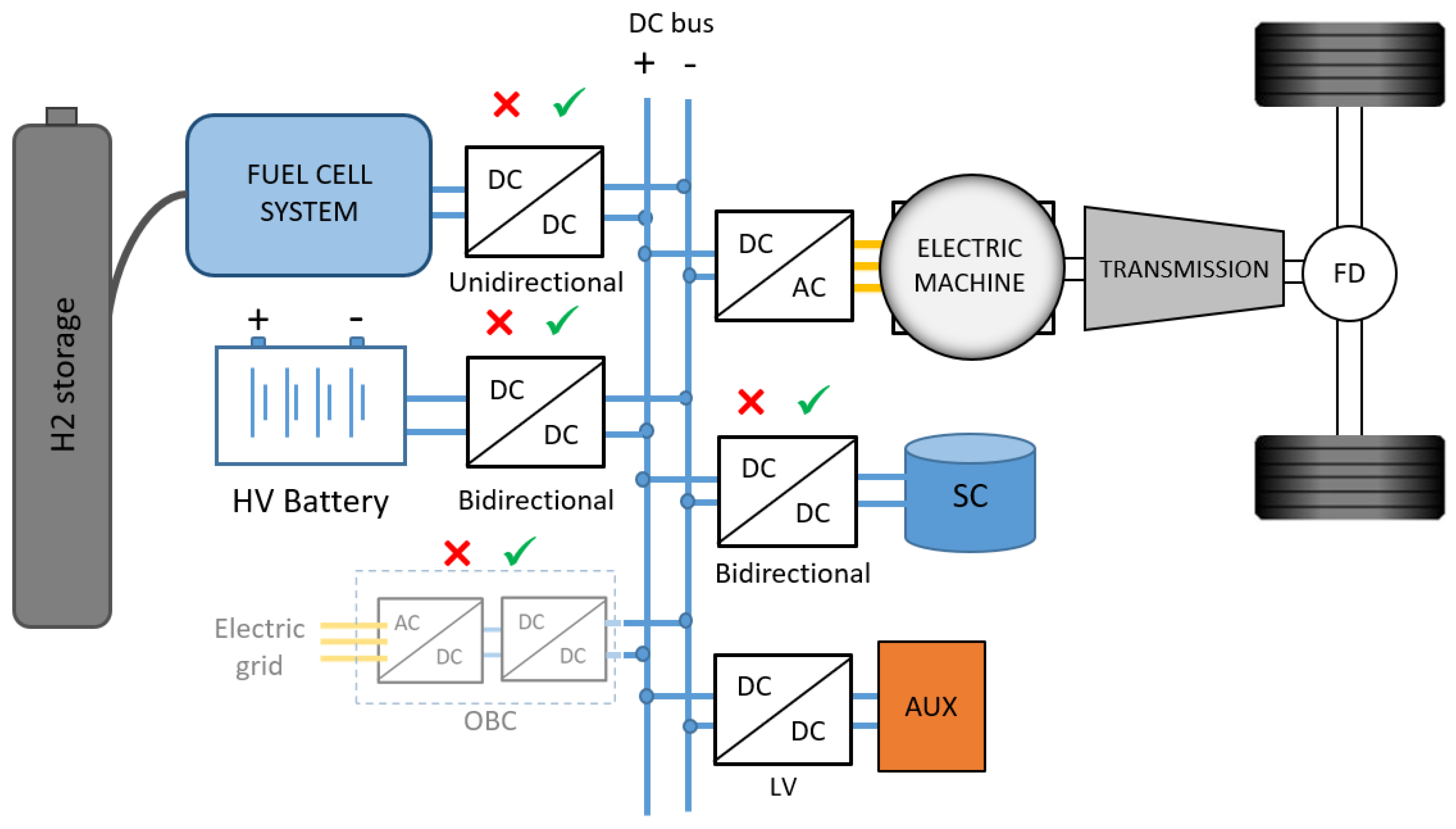
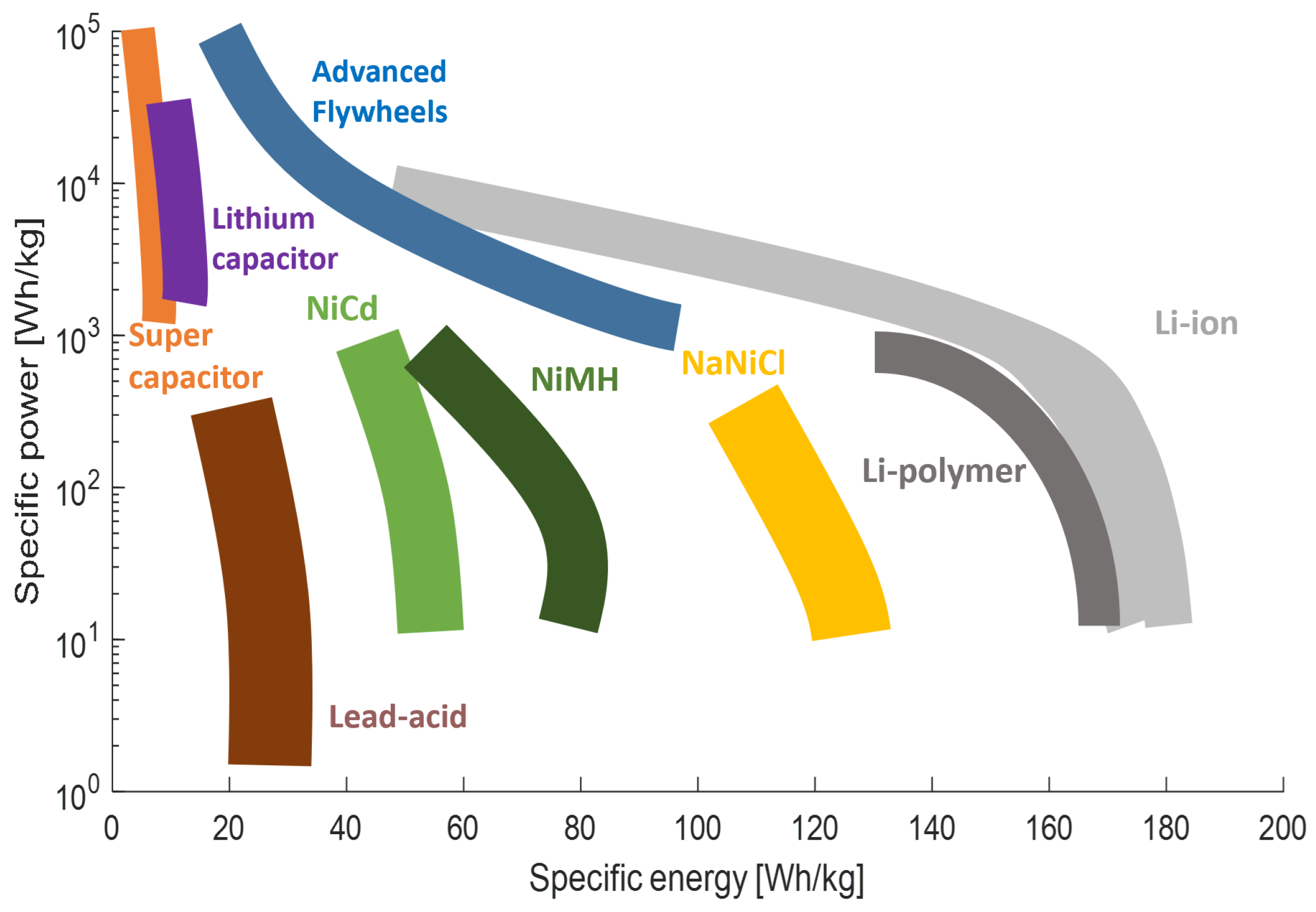
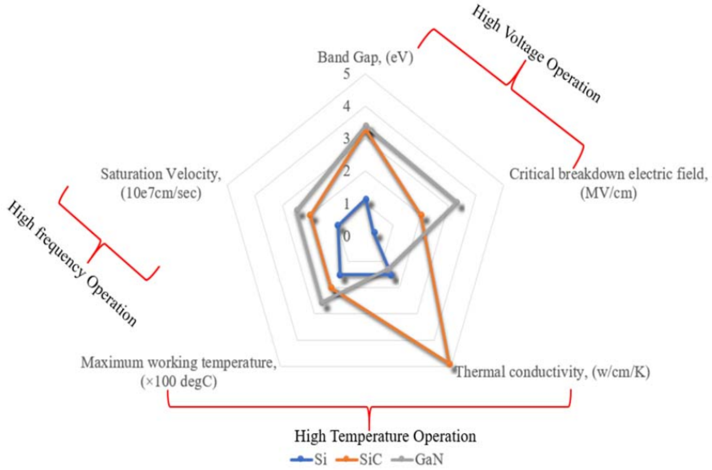
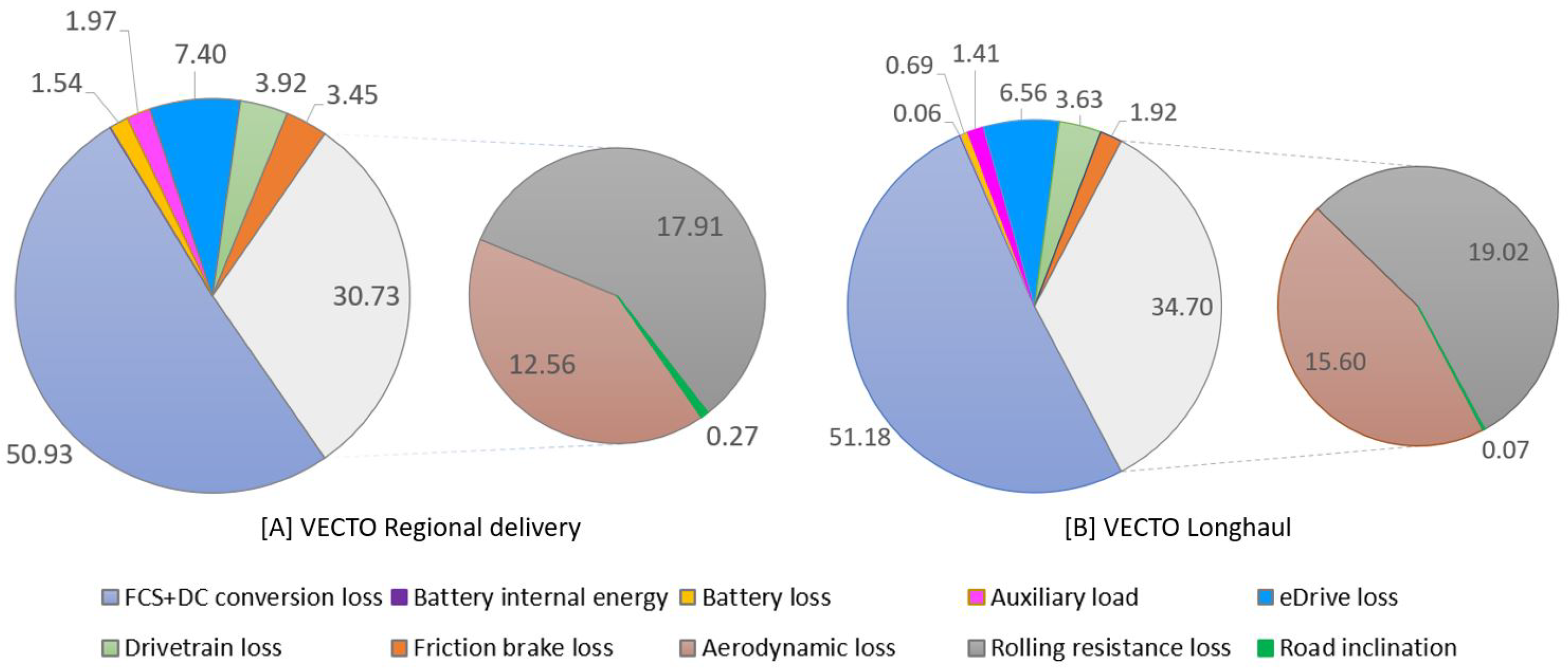
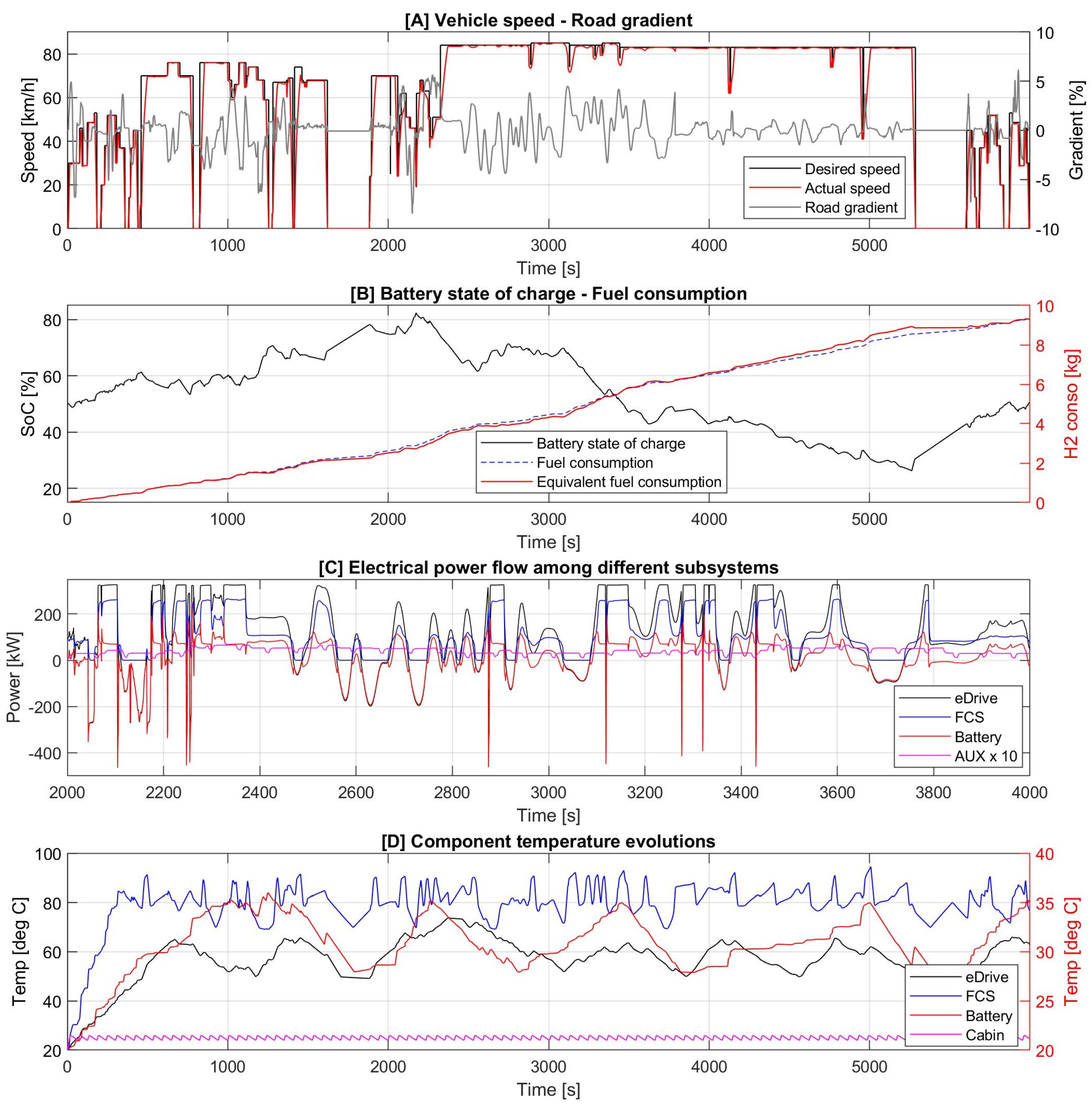
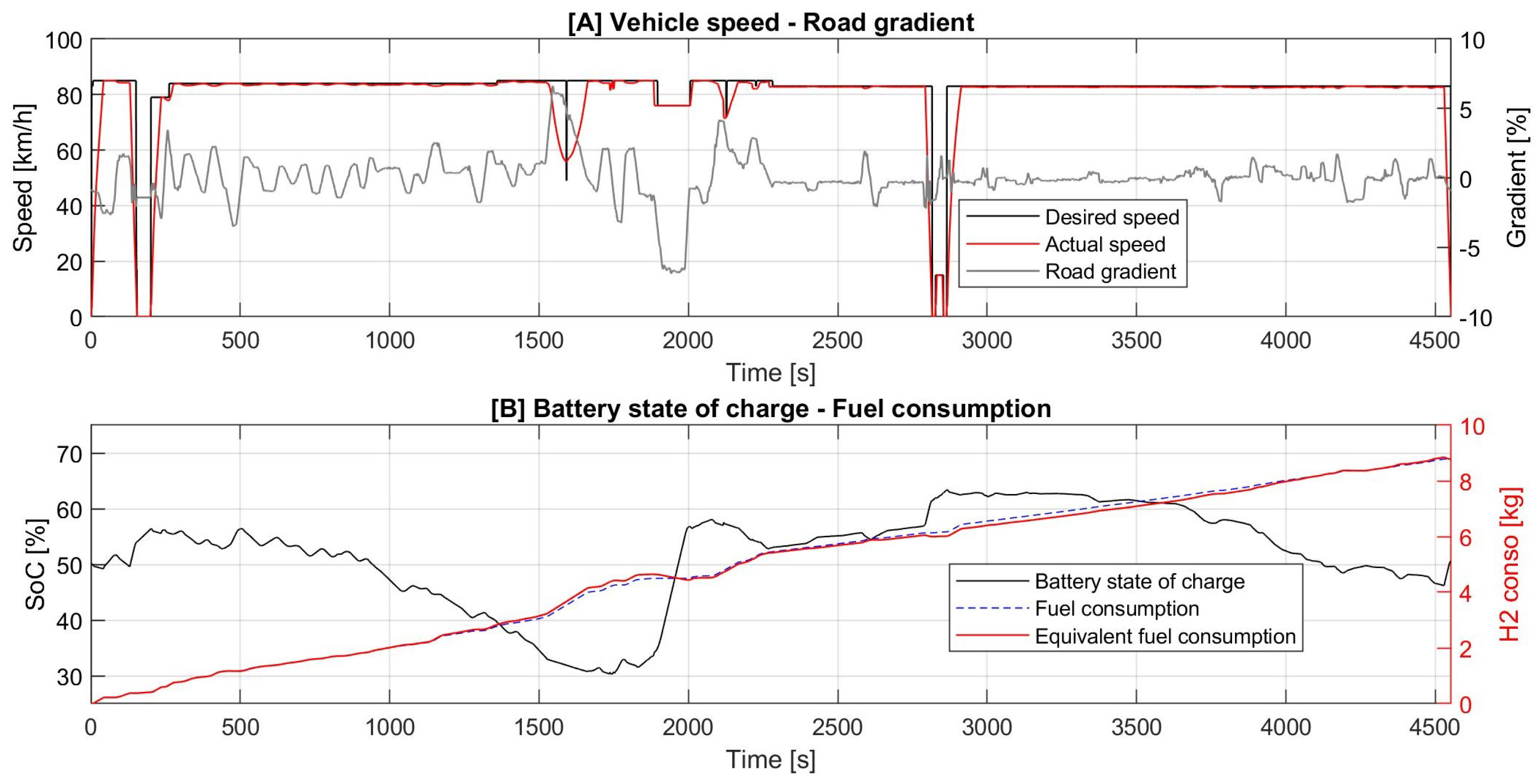
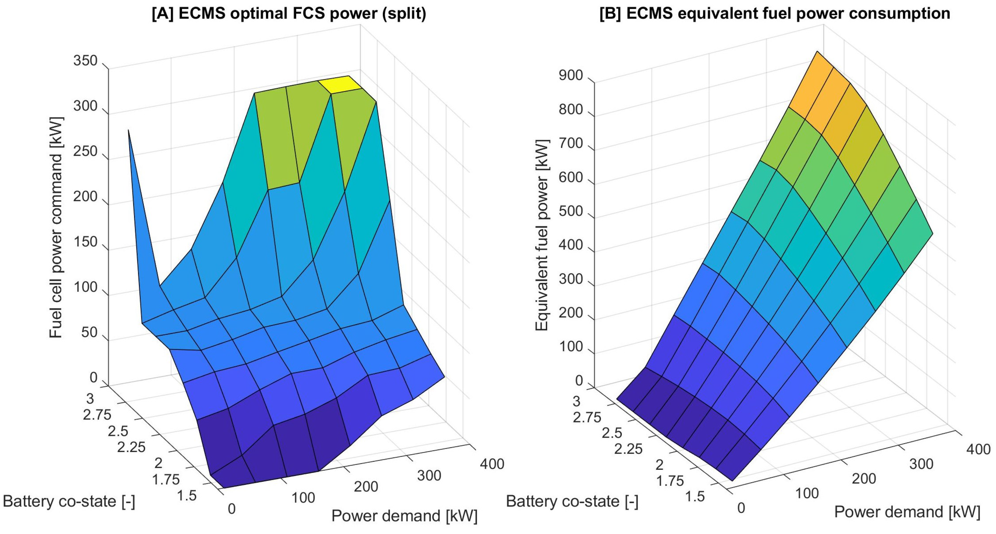
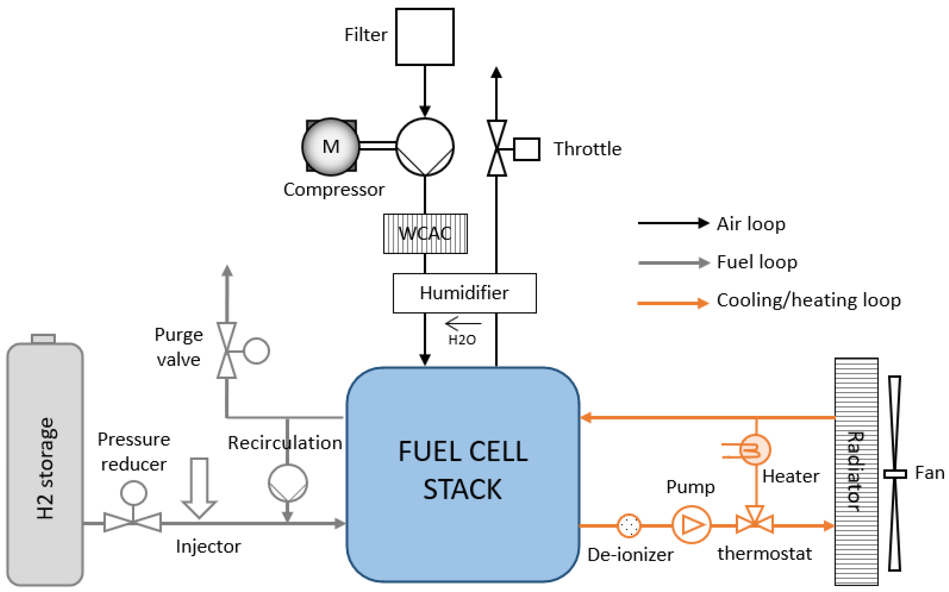
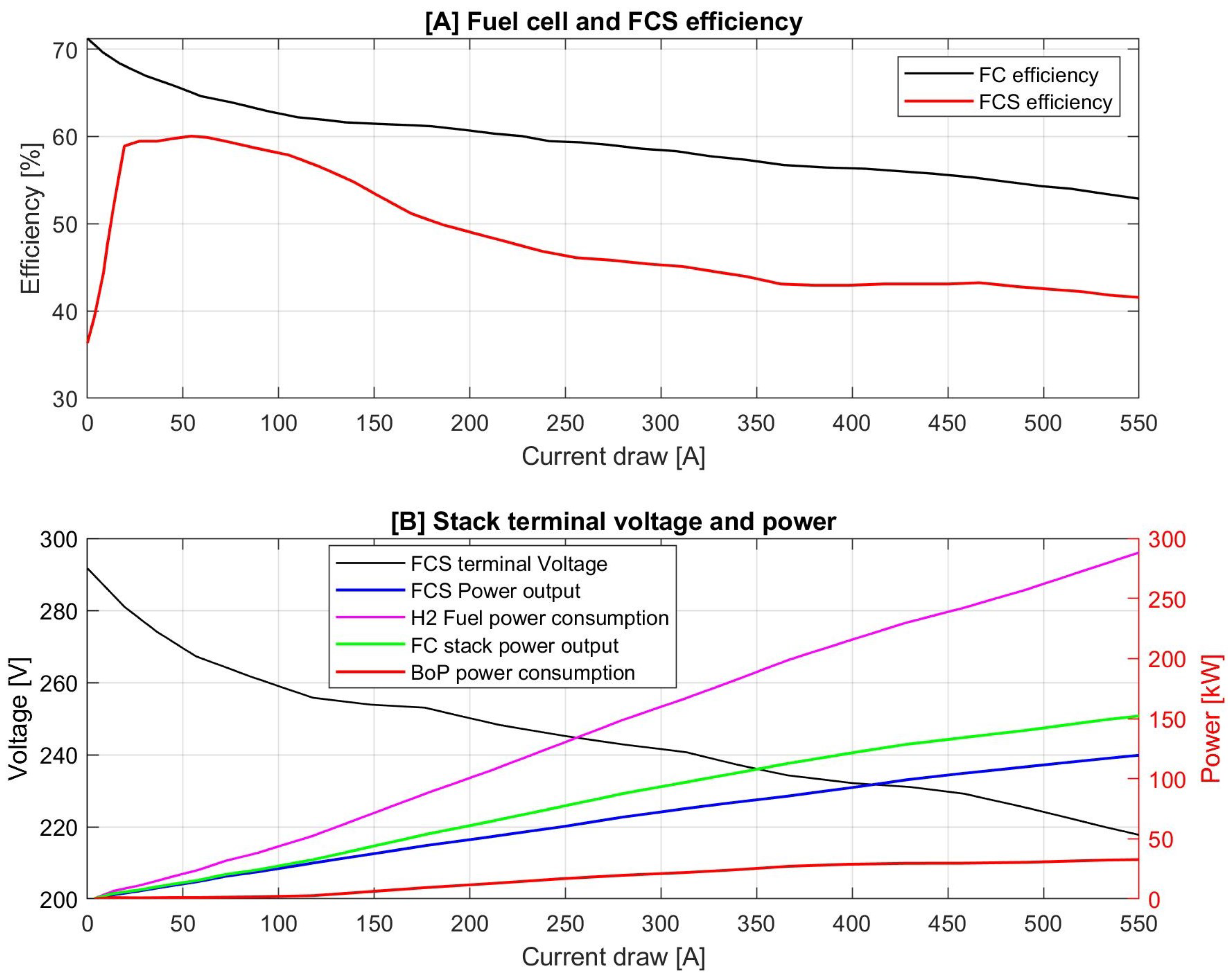
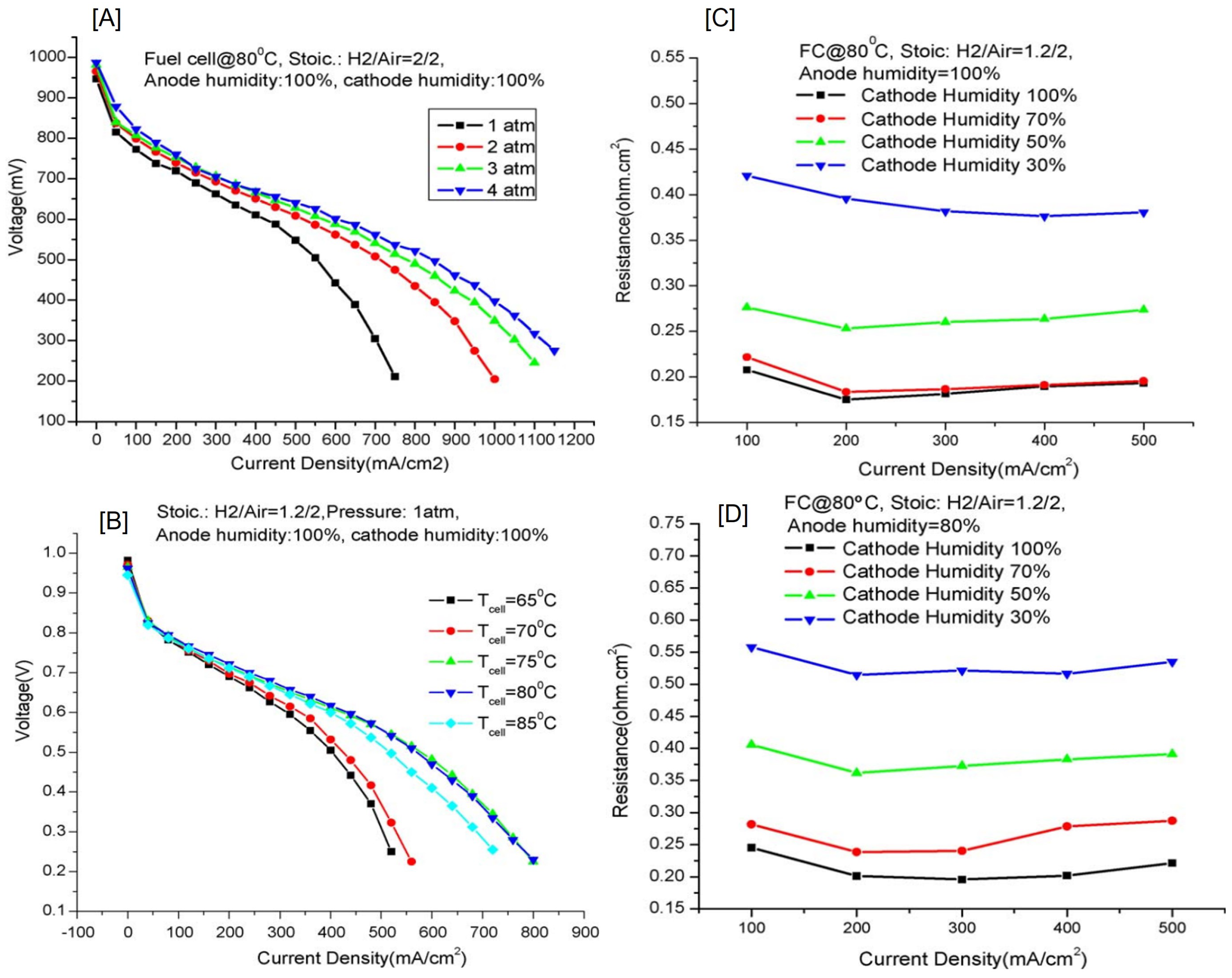
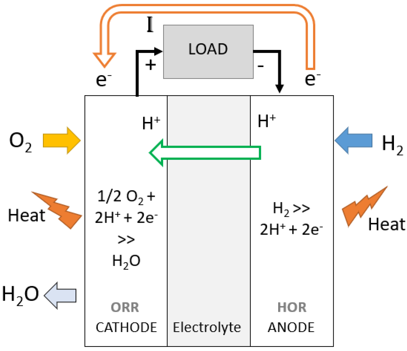
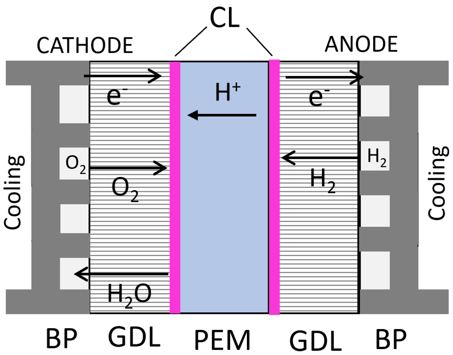
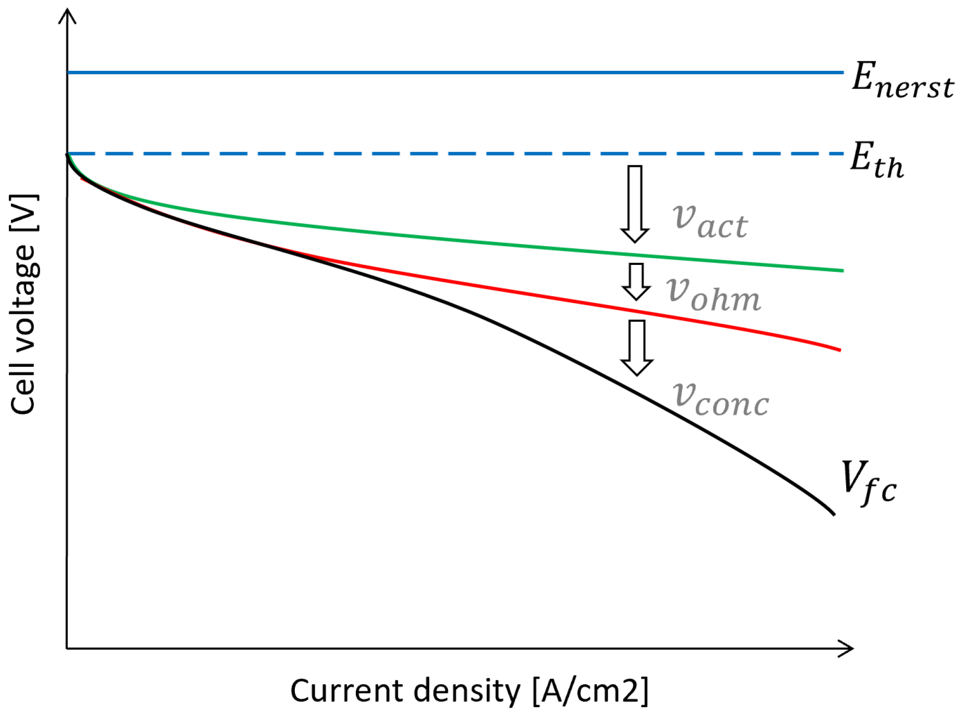
Figure 1. Generic fuel cell electric vehicle (FCEV) powertrain topology including fuel cell system (FCS), HV battery, electric drive, supercapacitor (SC), transmission, LV auxiliary loads, onboard charger and related power electronics converters.
Energies 15 09557 g001
Figure 2. Comparison of specific power and specific energy capacities for different energy storage systems (ESS): electrochemical batteries, supercapacitors and flywheels [114,115,116].
Energies 15 09557 g002
Figure 3. Material properties of Si-, SiC- and GaN-based semiconductors [129].
Energies 15 09557 g003
Figure 4. Percentage distribution of H 2 fuel energy expenditures and losses among different powertrain subsystems and driving resistances for 40-tonne fuel cell truck running on (A) VECTO Regional Delivery and (B) Longhaul drive cycles.
Energies 15 09557 g004
Figure 5. Simulation results for HD FCEV truck running on VECTO Regional delivery cycle: (A) distance based desired and actual vehicle speed, road gradient; (B) battery state of charge, cumulative and equivalent H 2 fuel consumption; (C) electrical power flow among FCS, HV battery, eDrive and auxiliary load governed by the ECMS strategy; and (D) component temperature evolution.
Energies 15 09557 g005
Figure 6. Simulation results for HD FCEV truck running on VECTO Longhaul cycle: (A) distance based desired and actual vehicle speed, road gradient; and (B) battery state of charge, cumulative and equivalent H 2 fuel consumption.
Energies 15 09557 g006
Figure 7. (A) ECMS optimal FCS power and (B) equivalent battery corrected fuel power consumption for the current 40T FCEV truck use case as a function of overall traction-auxiliary power demand and battery co-state. Lower co-state makes the battery energy cheaper and thus uses less FCS where as a higher co-state makes battery energy expensive promoting greater usage of the FCS.
Energies 15 09557 g007
Figure 8. Balance of plant subsystems supporting functioning of the fuel cell stack include air, fuel and thermal management systems.
Energies 15 09557 g008
Figure 9. (A) Fuel cell stack and fuel cell system energy conversion efficiencies based on current draw inspired from Toyota Mirai 2 bench-marking tests performed by AVL and FEV, (B) corresponding stack terminal voltage drop and FCS, FC stack, BoP components, H 2 fuel power [149,158].
Energies 15 09557 g009
Figure 10. Effect of (A) pressure, (B) temperature and (C,D) cathode and anode humidity on proton exchange membrane fuel cell (PEMFC) performance as experimentally tested by Yan et al. [169,170].
Energies 15 09557 g010
Figure 11. Proton exchange membrane fuel cell hydrogen oxidation and oxygen reduction reactions (HOR and ORR) at anode and cathode generating electropotential across the external electrical load.
Energies 15 09557 g011
Figure 12. Fuel cell membrane electrolyte assembly (MEA) comprising of bipolar plates (BP) with cooling channels; gas diffusion layer (GDL); catalyst layer (CL); and proton exchange membrane (PEM) along with corresponding ion transport mechanism [193].
Energies 15 09557 g012
Figure 13. Fuel cell ideal Nerst voltage E n e r s t , thermodynamic open circuit voltage E t h , polarisation curve with actual terminal voltage V f c and voltage drop due to activation V a c t , ohmic V o h m and concentration loss effects V c o n c dominant across different parts of the current density range.
Energies 15 09557 g013
Figure 14. Integrated multi-level energy and thermal management framework including external layer, supervisor layer, decision layer, control layer and safety layer for complete powertrain control.
Energies 15 09557 g014
Table 1. List of current and upcoming fuel cell electric long-haul heavy-duty vehicle initiatives.
ManufacturerInitiativeFCS [kW]eDrive [kW]Battery Capacity [kWh]Tank Capacity [kg]GCW [kg]Ref.
HyundaiXcient95 × 235073.23236,000[70]
ESORO (MAN)Coop logistics1002501203134,000[71,72,73]
VDLMedium H2-Share88210843027,000[56]
VDLHeavy H2-Share88210723044,000[57]
IVECOH2Haul100 × 248080 × 26542,000[58]
US HybridClass 8 Drayage803203638.5636,000[74]
Toyota-KenworthAlpha, Beta226500124036,000[75,76]
Scania-Asko-90290563327,000[77]
CumminsClass 890–18033010023.536,000[78]
Nikola motorsTre120480708040,000[79]
TransPower BAEZECT electric1003001003036,000[62,63]
VDL (DAF)Waterstofregio 2.060--3044,000[2]
AVLFC4HD310540523042,000[80,81]
Mercedes-BenzGenH2150 × 23307080-liquid40,000[82,83]
VOLVO TrucksFuel cell truck150 × 2---65,000[84]
CATHYOPECamion 44 tonnes170390-4644,000[85]
DAFREVIVE E-trucks30–8021015015–3826,000[64,65]
ScaniaREVIVE Renova30–8021015015–3826,000[64,65]
Mercedes FAUNHECTOR ENGINIUS30 × 3-8516.4 at 700 bar-[86,87]
Mercedes SEMATHECTOR30 × 2-85–11220 at 700 bar-[86,88]
CoachyfiedBus demonstrator----19,500[89,90]
Renault SYMBIOMaxity H220474244500[54]
Mitsubishi150e Canter75135-107500[91]
UPS HydrogenicsClass 631-451012,000[92]
Caetano ToyotaH2 city gold bus601804437.5-[59]
Solaris BallardUrbino 12 H2 bus70125 × 23037.5-[60]
VDLGIANTLEAP city bus601602163018,745[61]
RampiniHydrogen Ale bus16-80–9035-[93]
SafraHyCity45125 × 21303521,000[94]
Van HoolA330 fuel cell bus12085 × 2535016,000[95]
TATAStarbus fuel cell85186-14.5-[96]
Mercedes eCitaroRange extender bus602502433520,000[97]
Table 2. Comparison of various H 2 fuel onboard storage techniques for long-haul heavy-duty road mobility [146,147].
MethodVolumetric Density [gH 2 /L]Gravimetric Density [gH 2 /kg]Pressure
[bar]
Temperature
[ ° C]
Compressed 35016 [140]55350Ambient
Compressed 70027 [86,140]57 [148]700Ambient
Liquid36 [140]751 to 70−253 to −244
Cryo compressed7255300−150 to −240
Metal hydride (NaAlH 4 )703520260 to 425
Metal hydride (LiBH + MgH 2 )8080--
Metal borohydride (AL(BH 4 ) 3 )70100105−140
Liquid organic hydrogen carrier5665AmbientAmbient
Metal organic framework13501 to 350−203 to ambient
Table 3. Overall simulation results for the HD 40-tonne fuel cell truck: Cumulative fuel energy consumption, SoC corrected fuel energy consumption, traction energy expenditure and overall tank-to-wheel (TTW) efficiency for VECTO Regional delivery and Longhaul drive cycles.
Drive CycleH2 Cumulative/dSoC Corrected Equivalent Consumption [kWh (kg/100 km)]Traction Energy (Overall TTW Efficiency) [kWh (%)]
VECTO Regional Delivery310.4 (9.31)/310.1 (9.3)95.4 (30.73%)
VECTO Longhaul292.8 (8.78)/292.5 (8.77)101.6 (34.69%)
Table 4. Average operating efficiencies of various powertrain components from simulation of the 40-tonne fuel cell truck use case running on VECTO Regional delivery and Longhaul cycles.
SubsystemAverage Operating Efficiency: Regional Delivery [%]Average Operating Efficiency: Longhaul [%]
FCS + DC/DC49.148.8
HV battery95.295.6
eDrive89.388.7
Transmission + Differential93.993.1
Table 5. Vehicle specifications for HD fuel cell truck simulation.
ParameterValue
Overall vehicle mass [kg]40,000
Drag coefficient [-]0.54
Frontal area [m 2 ]9.7
Rolling resistance coefficient [-]0.0051
Wheel radius [m]0.507
Wheel inertia [kgm 2 ]15.5 × 18
Differential ratio [-]2.71:1
Differential efficiency [%]VECTO
Transmission ratios [-]18.45:1; 9.96:1; 5.72:1
Transmission efficiency [%]98
eDrive power; max torque; max speed; mass [kW; Nm; RPM; kg]300; 750; 8000; 200
Battery nominal energy, voltage, charge capacity; mass [kWh;V; Ah; kg]30.6; 666; 46; 220
Fuel cell system voltage, power; parallel stacks; mass [V; kW; -; kg]Section 3.3; 360; 3; 630
Ambient temperature and air density [ ° C; kg/m 3 ]20; 1.225
Publisher’s Note: MDPI stays neutral with regard to jurisdictional claims in published maps and institutional affiliations.

