Article

Distributed Permanent Magnet Direct-Drive Belt Conveyor System and Its Control Strategy

School of Electrical and Control Engineering, Xi’an University of Science and Technology, Xi’an 710054, China
*
Author to whom correspondence should be addressed.
Energies 2022, 15(22), 8699; https://doi.org/10.3390/en15228699
Submission received: 30 September 2022 / Revised: 14 November 2022 / Accepted: 17 November 2022 / Published: 19 November 2022

Abstract

:
The long-distance traditional belt conveyor driven by a single high-power motor has the problems of excessive tension increments and sharp fluctuations in speed and tension. This paper designs a distributed permanent magnet direct drive belt conveyor system. The dynamic model of the conveyor belt unit and the permanent magnet motor is analyzed. The multi-motor ring coupling control strategy and the double sliding film direct torque control strategy of the belt conveyor system are formulated. The mechanical-electrical coupling dynamic model of the belt conveyor system is built. Using MATLAB/Simulink modeling and simulation, the vector control strategy and electromechanical coupling dynamic behavior of the traditional belt conveyor system and the distributed permanent magnet direct drive belt conveyor system under light load start-up and local variable load operation conditions are studied. The results show that: the distributed permanent magnet direct drive belt conveyor system significantly reduces the peak of conveyor belt tension increment; the time spent under the starting light-load operation condition is shorter, and the fluctuation amplitude of speed and tension is smaller; it is possible to reduce the speed and tension fluctuation range of the conveying system and improve the robustness of the conveying system under local variable load conditions. Experiments have verified that increasing the number of drive motors in a conventional belt conveyor can suppress the disturbance caused by local load changes, and the distributed permanent magnet direct-drive belt conveyor has better dynamic regulation performance.

1. Introduction

In modern bulk material conveying industries, belt conveyors are widely used in the mining, mineral processing and power generation industries because of their strong adaptability, long distance, simple maintenance and easy centralized management [1,2,3,4,5]. At present, the belt conveyor mostly adopts the centralized drive mode of asynchronous motor and reducer [6,7]. This centralized drive mode not only has technical deficiencies, such as a long transmission line, poor transmission efficiency and poor reliability, but also has problems such as a slow dynamic adjustment of tension and speed of the conveyor belt.
Since the 21st century, continuous breakthroughs in permanent magnet drive technology in motor structure design and related control technology have created favorable conditions for the application of high-power permanent magnet motors in coal mine transportation equipment. In the field of permanent magnet motor research for mining belt conveyors, compared with the asynchronous motor, the permanent magnet motor can greatly improve the power factor without an excitation current and does not connect to the deceleration device to directly drive the load. Therefore, it is very suitable for the low speed and high torque operation conditions of mine transportation equipment [8]. SEMENOV designed a high performance five-phase permanent magnet synchronous motor for mining [9]. SEMYKINA designed a permanent magnet direct-drive electric roller without gear structure for the operating conditions of the belt conveyor [10].
The application of permanent magnet motors in mining transportation equipment advances the process of coal mine intelligence, improves transportation efficiency, and saves energy. However, with the development of industrial process, the requirements for long distance and large capacity belt conveyor systems are further enhanced, and it is difficult to solve the problems of excessive power demand and reduced transmission efficiency arising from long distance transportation by using a single permanent magnet motor to drive the belt conveyor. Therefore, the multi-point permanent magnet motor-drive technology is being gradually developed [11]. Chunyu Yang presents an energy model and a parameter identification method for dual-motor-driven belt conveyors whose speed sensors are not available [12]. Xiaolin Yang designed a belt conveyor driven by multiple permanent magnet motors in the middle of the head and fuselage [13]. Although the above research design improves the transmission efficiency of the belt conveyor, there is no further study on the excessive tension peak value and the violent tension fluctuation caused by the long conveying distance.
In response to the above existing problems, a permanent magnet direct-drive belt conveyor system with multiple permanent magnet direct-drive motors as idlers and as the power source of each conveying section is designed. The multi-motor ring coupling control strategy and the direct torque control strategy of double sliding film are adopted. Compared with the traditional belt conveyor, the conveying system not only reduces the peak tension of the conveying system, but also improves the dynamic adjustment performance, thereby improving the production efficiency. The research results can provide a theoretical reference for the research and promotion of multi-permanent-magnet drive motor technology for belt conveyors.

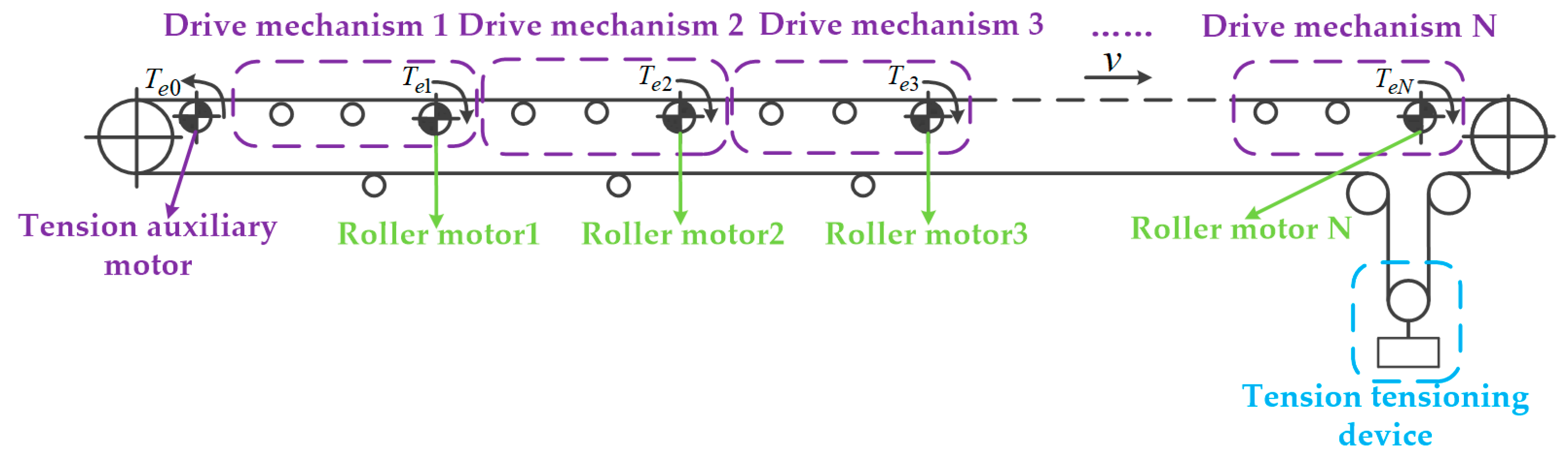
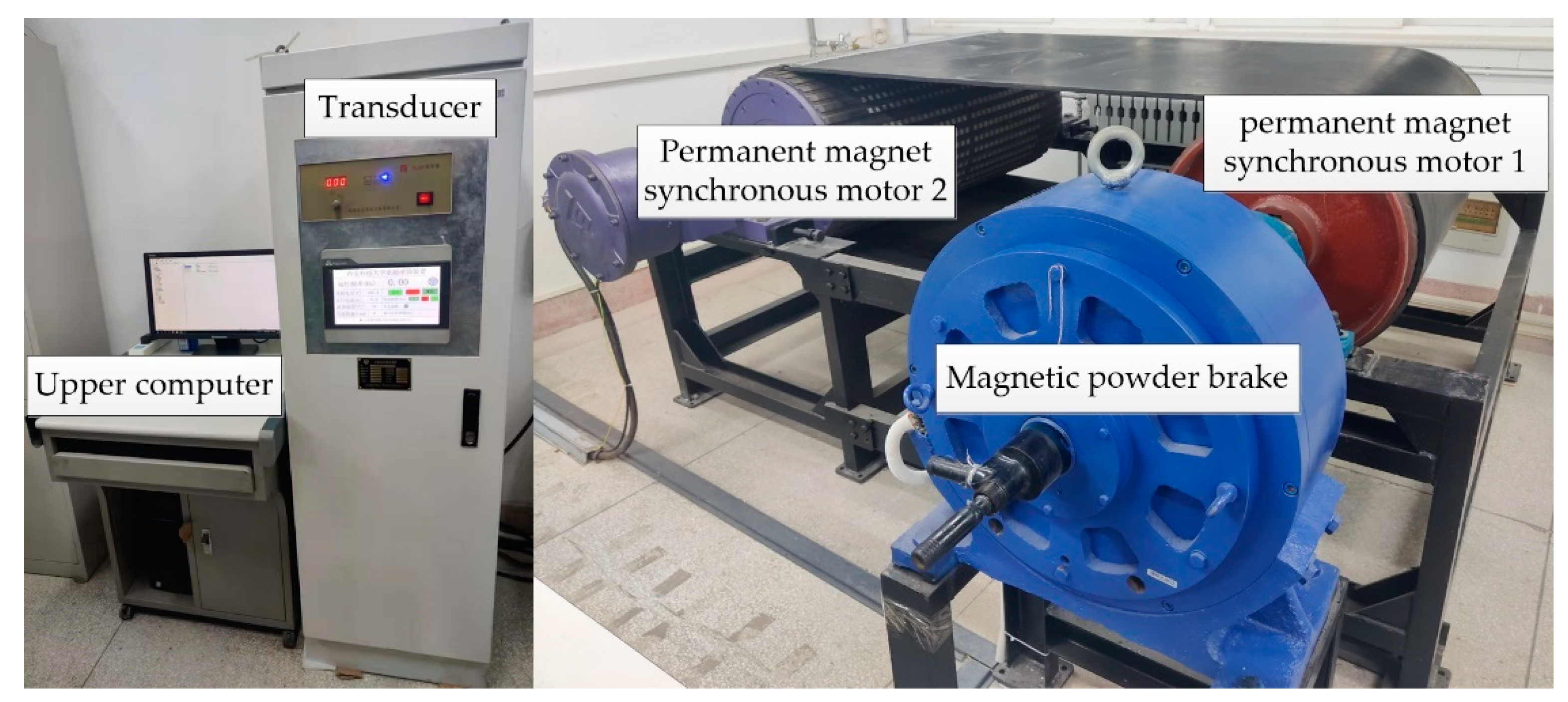
2. System Composition

The distributed permanent magnet direct-drive belt conveyor system is the result of modularizing the structure of traditional belt conveyor systems with long distance, large tension and high power. In the conveyor, there is a plurality of low-speed and high-torque external rotor permanent magnet motors (referred to as roller motors) similar to the volume of the rollers. These roller motors not only replace the normal operation of the original roller support conveying system, but also provide power for the conveying system. Each idler motor and dozens of idlers in the bearing section form a relatively independent driving mechanism. The tension at the head and end of each driving mechanism remains equal, which effectively reduces the peak value of the conveyor belt tension. Calculated only by the tension increment of the conveyor belt on the bearing section, the peak value of the tension increment of the bearing section of the distributed permanent magnet direct-drive conveying system composed of n sets of driving mechanisms is approximately 1/ n of the traditional belt conveying system. Typical horizontal-state distributed permanent magnet direct-drive belt conveyor structure is shown in Figure 1.
In addition to retaining the traditional tensioning device, this design can choose to install a tension auxiliary motor at the initial end of the bearing section to stabilize the tension at the initial end of the bearing section at the set value. After adding the tension auxiliary motor to the belt conveyor, the power of the motor of the tensioning device can be further reduced. In the case of proper design, the permanent magnet motor in the whole conveyor can adopt the same specifications and reduce the cost.

3. Dynamic Model of Conveying System

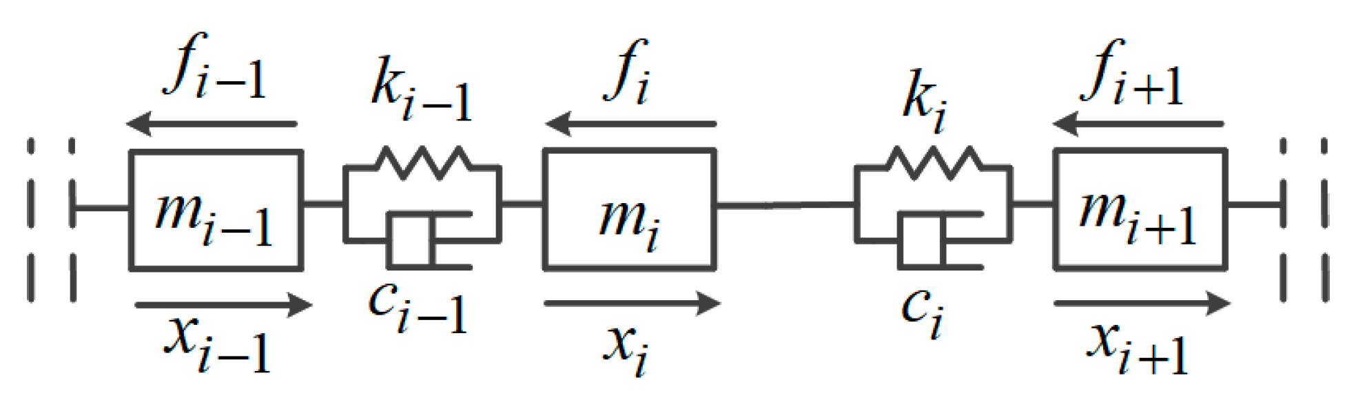
3.1. Dynamic Model of Conveyor Belt

The Kelvin–Voigt viscoelastic mechanical model is widely used in constructing dynamic models of conveyor belts [14,15]. The conveyor belt is divided into many units, and the dynamic model of each unit is constructed. Figure 2 shows the dynamic model of conveyor belt unit i. Under the influence of various resistances in the conveying process, unit i deforms with adjacent units i − 1 and i + 1, so the change of conveyor belt tension can be obtained by calculating the displacement of two adjacent units.
The tension F i between conveyor belt unit i and unit i − 1 is given by
F i = k i ( x i x i 1 ) + c i ( x ˙ i x ˙ i 1 )
where k i , c i , x i , x ˙ i are the stiffness coefficient, resistance coefficient, displacement and velocity of the conveyor belt unit i; x i 1 , x ˙ i 1 are the displacement (m) and velocity (m/s) of element i − 1.
The tension F i + 1 between unit i + 1 and unit i is given by
F i + 1 = k i + 1 ( x i + 1 x i ) + c i + 1 ( x ˙ i + 1 x ˙ i )
where k i + 1 , c i + 1 , x i + 1 , x ˙ i + 1 are the stiffness coefficient, resistance coefficient, displacement (m) and velocity (m/s) of conveyor belt unit i + 1. The difference of conveyor belt material determines its stretch deformation. In the case of the same material of the whole conveyor belt, the stiffness coefficient and damping coefficient of each unit of the conveyor belt are the same, k n + 1 = k n , c n + 1 = c n .
According to the standard DIN22101 and the paper [16,17,18], the conveyor belt will be subjected to the rotation resistance of the idler, the indentation resistance of the belt and the idler, the tilt resistance and the resistance caused by the guide groove. In this paper, the sum of these resistances is recorded as f i . In addition, in the non-uniform state, the acceleration force F a i will be required. Therefore, the force Equation (3) of the conveyor belt unit i is expressed as
F i + 1 F i = f i + F a i
where F a i = m i a , a , m i is the instantaneous acceleration (m/s2) and mass (kg) of conveyor belt unit i.
According to Equation (3), the reason for the fluctuation of conveyor belt tension along the conveying direction is the constant change of resistance and acceleration on each unit of the conveyor belt. When the transportation speed and flow rate are constant, the resistance and acceleration of each unit of the conveyor belt remain unchanged, and the tension difference between adjacent units is the same. The tension of the conveyor belt will increase proportionally along the transportation direction.
When the resistance of a unit of the conveyor belt changes suddenly, taking the unit i − 1 in Figure 2 as an example, assuming that the resistance increment of unit i − 1 is f b , it will cause a sudden decrease in the speed of unit i. At this time, the value of F i is negative, which will weaken the influence of the resistance increment f b on the tension of conveyor belt. However, because the speed of the conveyor belt is generally low, the weakening degree caused by F i is small. Tension F i must rise under the action of resistance increment f b and pass to unit i. For unit i, its surge resistance value is f b F i , which will also cause its speed to decrease, but it will be higher than the speed of unit i − 1, satisfying Equation (1). Finally, an increase in the resistance of a certain section of the conveyor belt causes a decrease in the speed of the entire conveyor belt.

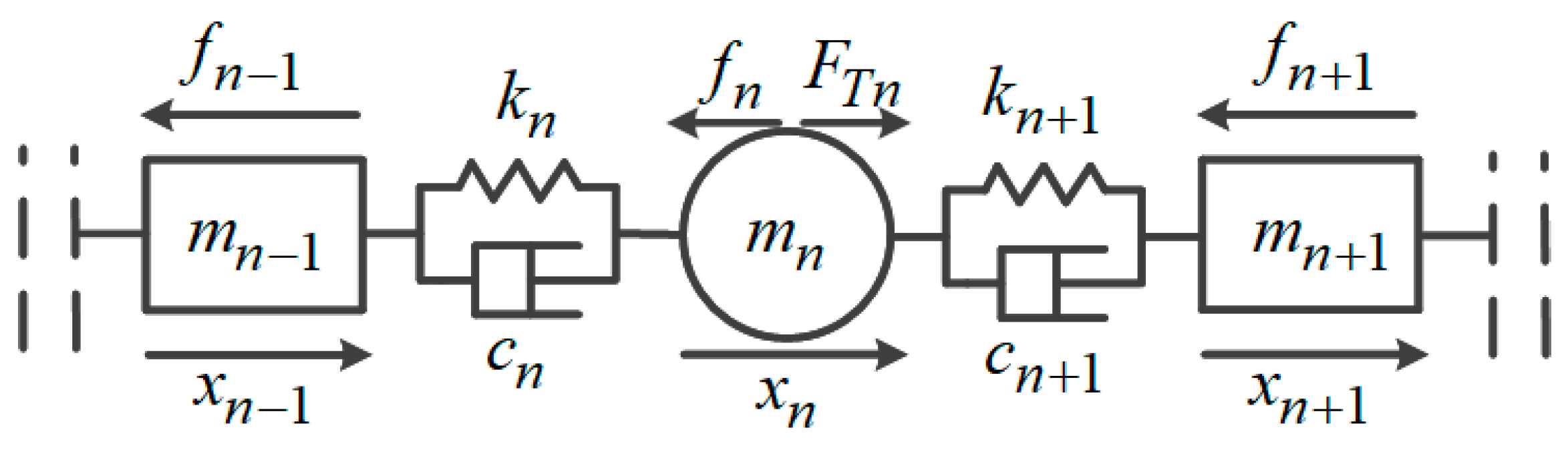
3.2. Dynamic Model of Roller Motor

The roller motor is distributed below the conveyor belt as a roller, and the motor is always in contact with the conveyor belt without considering slipping. The Kelvin–Voigt viscoelastic mechanical model is also selected to construct the dynamic model of the roller motor. Figure 3 is the dynamic model of the roller motor n on the conveyor belt.
Tension F n between roller motor n on conveyor belt and conveyor belt unit n − 1 is given by
F n = k n ( x n x n 1 ) + c n ( x ˙ n x ˙ n 1 )
where k n , c n are the stiffness coefficient and resistance coefficient of the conveyor belt at the motor n, respectively; x n , x ˙ n are the roller motor n drag conveyor belt displacement, speed; x n 1 , x ˙ n 1 are the displacement and velocity of conveyor belt unit n − 1.
Tension F n + 1 between roller motor n on conveyor belt and conveyor belt unit n + 1 is given by
F n + 1 = k n + 1 ( x n + 1 x n ) + c n + 1 ( x ˙ n + 1 x ˙ n )
where k n + 1 , c n + 1 , x n + 1 , x ˙ n + 1 are the stiffness coefficient, resistance coefficient, displacement and velocity of the conveyor belt unit n + 1, respectively.
Compared with the conveyor belt unit, the roller motor n is not only subjected to rolling friction resistance f M n and acceleration force F M a n , but also provides traction F T n for the conveying system. Therefore, the force Equation (6) of the motor is expressed as
F n + 1 F n = f M n + F M a n F T n
where F a n = J ω ˙ , J is the rotational inertia of roller motor n (kg/m); F T n = T e n / r n , T e n is the load torque of the roller motor n ( N · m ); r n is the radius of the roller motor n (m); ω ˙ is the mechanical angular acceleration of the roller motor n (rad/s2).
According to Equation (6), when the transport speed and transport flow are constant, the load torque provided by the roller motor is constant, but it must be pointed out that the load torque of each roller motor can be different. When the resistance of a unit of the conveyor belt suddenly increases by f b , the fluctuation of the conveyor belt is transmitted to the roller motor. Due to the small distance between the distributed roller motors, the sudden increase resistance f b is weakened to a limited extent. In order to maintain its own speed stability, the roller motor will inevitably increase the output load torque T e . If the current roller motor cannot quickly respond to output sufficient load torque, the speed of the roller motor will be reduced, and the tension fluctuation caused by the sudden increase in resistance will continue along the transportation direction.

3.3. Output Power of Roller Motor

In the whole conveying system, the roller motor is the power source to overcome all kinds of resistance in the process of conveying, ensuring the tension balance of the whole conveyor belt. Combining Equations (3) and (6), the tension balance formula of the whole conveying system can be obtained
j = 1 i ( f j + F a j ) + j = 1 n ( f M j + F M a j ) = j = 1 n T e n r n
Equation (7) constrains the sum of the output electromagnetic torque of all motors, but does not limit the output electromagnetic torque of a single roller motor. In the actual transportation process, the material of the conveyor belt and the installation position of the roller motor constrain the effective electromagnetic torque range of the roller motor output to the conveying system. For the roller motor without feedback braking, to ensure that the maximum output traction will not cause slip between the motor and the conveyor belt [19], the following conditions need to be met:
0 F T F L ( e f · α 1 )
where F T is the motor output traction force (N); F L for the motor loose edge tension (N); f is the friction coefficient between the motor and the conveyor belt; α is the maximum enclosing angle between the motor and the conveyor belt (rad).

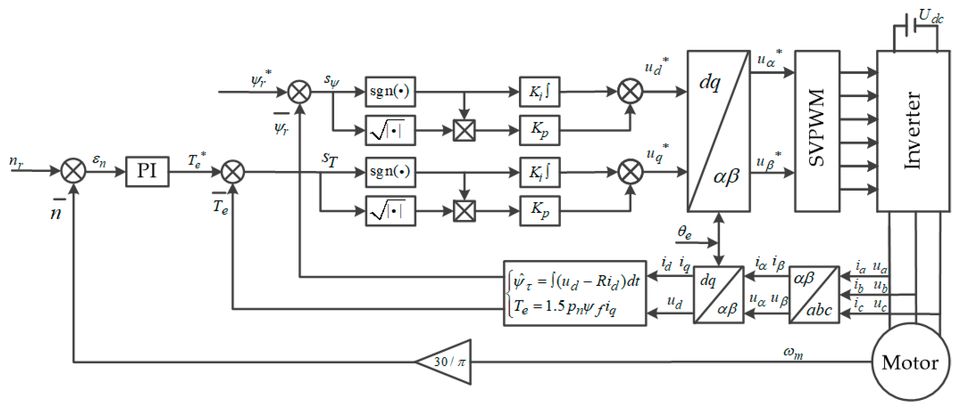
4. Vector Control Strategy Modeling

From the point of view of the operation efficiency of the roller motor and the stability of the conveying system, a situation in which the output power difference of an individual roller motor is too large is prevented, and the tension balance of the whole conveying system is realized. The tension auxiliary motor adjusts the load torque output to meet the set tension, and the roller motor adjusts the load torque output with the reference of the tension difference between the head and end of the respective driving unit. Both of them choose the direct torque control strategy based on double sliding mode control as the basic control strategy of the variable frequency speed regulation of the conveying system. At the same time, a multi-motor ring coupling control strategy is designed to perform the coordinated control of the roller motors of each driving mechanism in the conveying system.

4.1. Direct Torque Control Strategy Based on Double Sliding Mode Control

The mathematical model expression of surface-mounted three-phase PMSM in synchronous rotating coordinate system can be written as
u r = R i r + d ψ r d t + j ω e ψ r ψ r = ψ f + L s i r
where ψ f is the permanent magnet flux linkage (wb); ω e is the electric angular velocity (rad/s); R is stator resistance (Ω); L s is stator inductance (H); ψ r = ψ d + j ψ q , which is the stator flux space vector (wb); i r = i d + j i q , which is the stator voltage space vector (A).
The expression of electromagnetic torque T e be expressed as
T e = 3 2 P n ( ψ d i q ψ q i d ) = 3 2 P n ψ f i q
where P n is the number of poles of the motor.
When the direction of the stator flux linkage vector is consistent with the d -axis direction, ψ r = ψ d = ψ r , the flux linkage amplitude can be expressed as
ψ r = ( u d R i d ) d t
The sliding surface function of flux linkage is defined as
s ψ = ψ r * ψ r
Using the basic principle of second-order sliding mode control based on Lyapunov algorithm, the expression of flux linkage controller can be written as
u d * = K p | s ψ | r sgn ( s ψ ) + u s d d d t u s d = K i sgn ( s ψ )
where K p , K i are the adjustment factor, K p , K i > 0 .
The differential equation of electromagnetic torque T e can be expressed as
d d t T e = 3 2 P n ψ f d d x i q
The sliding surface function of torque is defined as
S T = T e * T e
Using the basic principle of second-order sliding mode control based on Lyapunov algorithm, the expression of torque controller can be written as
u q * = K p | s T | r sgn ( s T ) + u s q d d t u s q = K i sgn ( s T )
When the design parameter r = 0.5 , permanent magnet motor sliding mode control structure is shown in Figure 4.

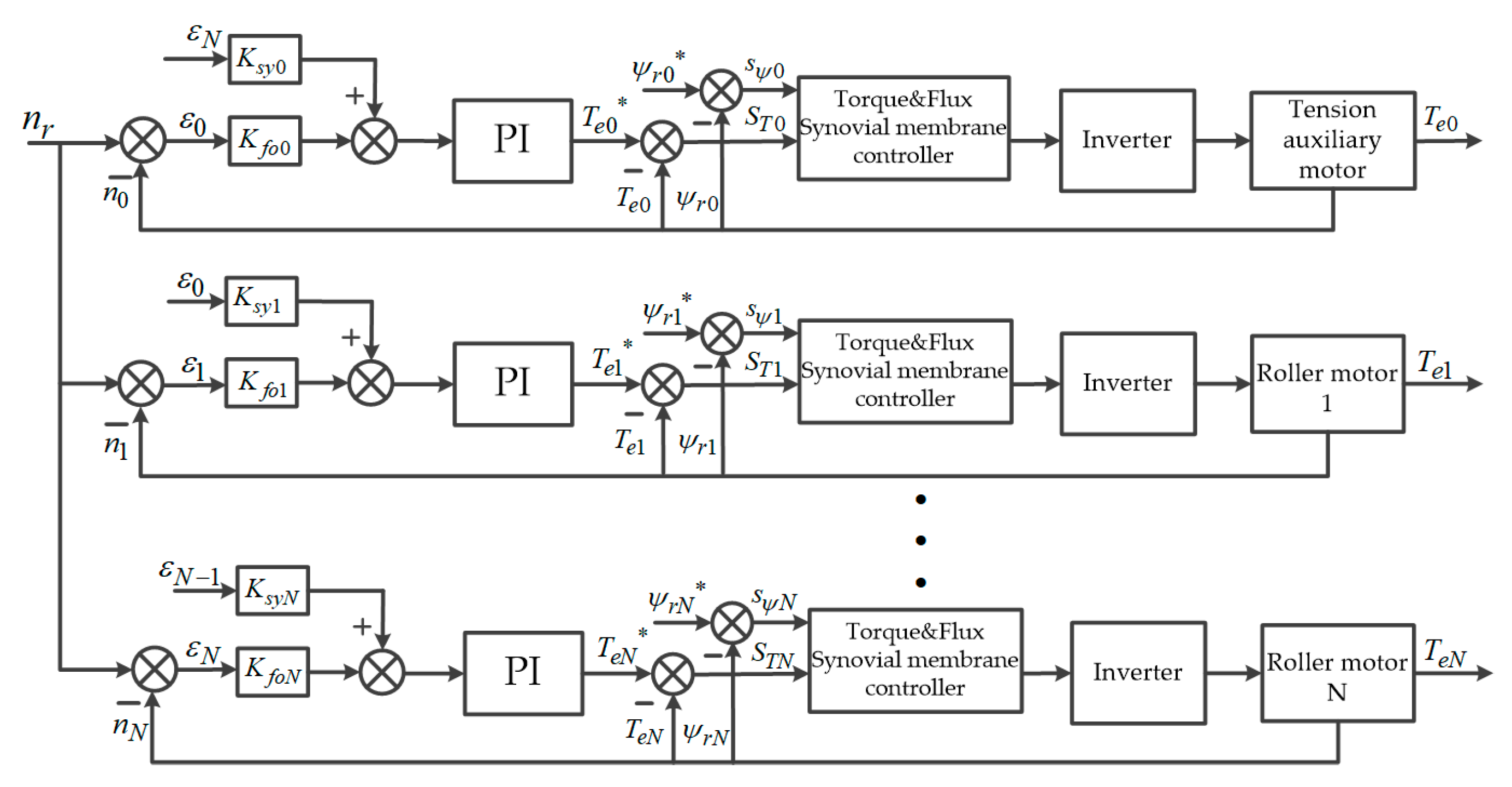
4.2. Multi-Motor Ring Coupling Control Strategy

Conveyors generally transport materials in a single direction. The sudden resistance of a unit during transportation will only cause speed and tension disturbances to the conveyor belt and the roller motor along the transportation direction. By comprehensively comparing the existing multi-motor control strategies [20,21], a multi-motor ring coupling control strategy is designed. When a single motor cannot overcome the tension fluctuation caused by the resistance mutation, the next motor adjusts its torque according to the speed of the front motor, so as to reduce the tension fluctuation and avoid continuing to affect the subsequent transportation links. In the logical framework of multi-motor ring coupling control strategy shown in Figure 5, the torque compensation of each motor only considers the speed error feedback of the previous motor along its own transportation direction.
Since the roller motor and the tension tensioning motor are connected by the conveyor belt, the synchronous speed error between the motors has a certain tolerance. The difference between the real-time speed and the rated speed of the motor is selected as the self-following error and the synchronization error transmitted to the adjacent motor, which can reduce the influence of a single motor on the whole conveying system. K s y is the synchronization error coefficient, K f o is the following error coefficient, K s y , K f o > 0 .

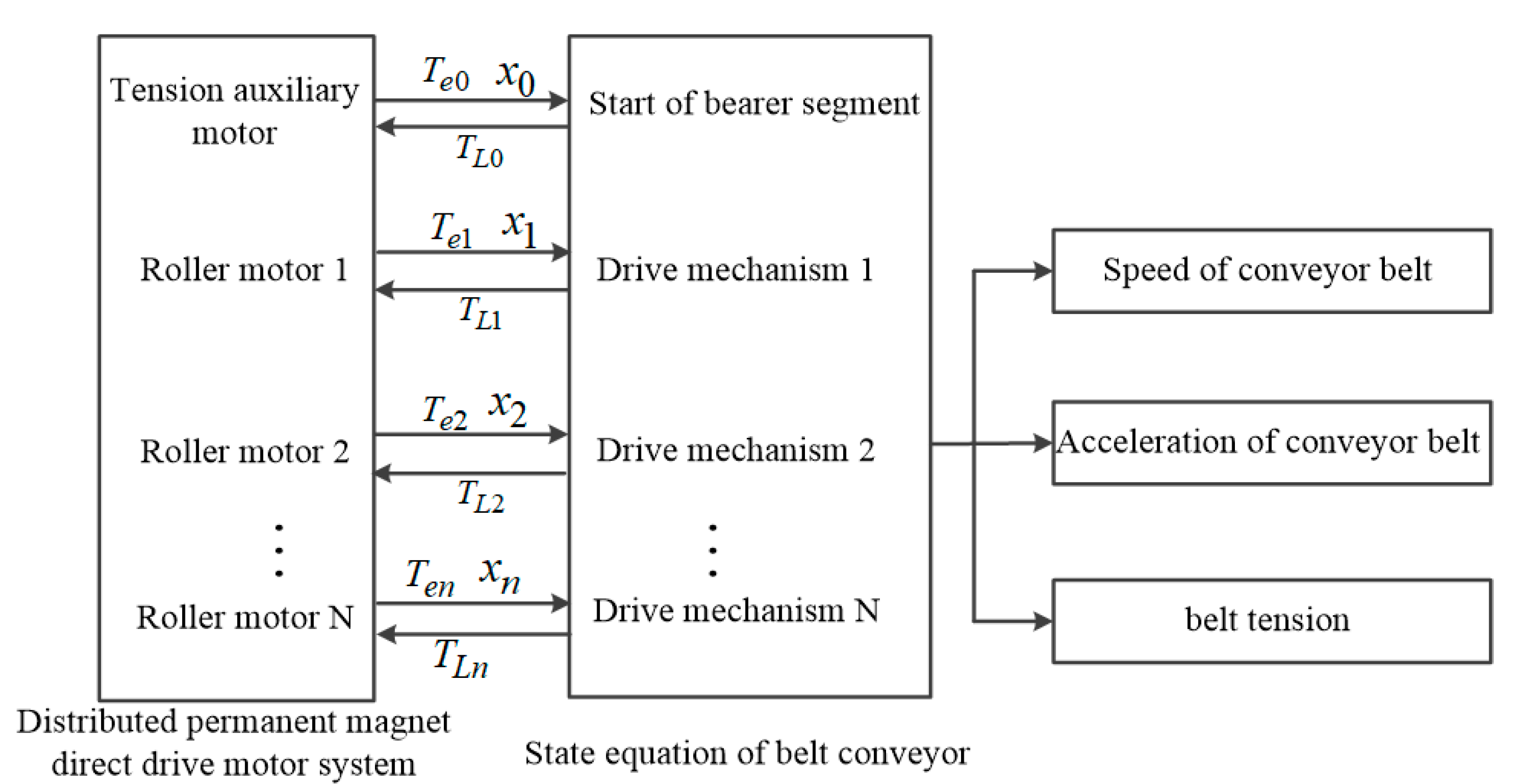
5. Mechanical-Electrical Coupling Dynamics Modeling

In order to study the dynamic behavior of the distributed permanent magnet direct-drive belt conveyor, the tension change of the conveyor belt is analyzed, and the mechanical-electric coupling model of belt conveyor is established. Based on the Kelvin–Vogit viscoelastic mechanical model, a discrete element model of the mechanical load dynamics of the distributed permanent magnet direct-drive belt conveyor is formed, as shown in Figure 6.
In the bearing section, there are n groups of roller motor drive mechanism models. Each group of models is composed of n mass-stiffness-damping units, plus the discrete unit of tension auxiliary motor. The bearing section is composed of n 2 + 1 dynamic discrete units to describe the resistance f i , mass m i , displacement x i , stiffness k i and damping c i of the conveyor belt; i = 11 ~ n n . The backhaul section is divided into m + 1 discrete units, m = n 2 ; on this basis, the dynamic equation of mechanical load is derived from the dynamic equation of discrete element model.
m 11 x ¨ 11 + k 11 ( x 11 x a ) + c 11 ( x ˙ 11 x ˙ a ) k 12 ( x 12 x 11 ) c 12 ( x ˙ 12 x ˙ 11 ) + f 11 = 0 m 12 x ¨ 12 + k 12 ( x 12 x 11 ) + c 12 ( x ˙ 12 x ˙ 11 ) k 13 ( x 13 x 12 ) c 12 ( x ˙ 13 x ˙ 12 ) + f 12 = 0 ...... m 1 n x ¨ 1 n + k 1 n ( x 1 n x 1 n 1 ) + c 1 n ( x ˙ 1 n x ˙ 1 n 1 ) k 21 ( x 21 x 1 n ) c 21 ( x ˙ 21 x ˙ 1 n ) + f 1 n F T 1 n = 0 m 21 x ¨ 21 + k 21 ( x 21 x 1 n ) + c 21 ( x ˙ 21 x ˙ 1 n ) k 22 ( x 22 x 21 ) c 22 ( x ˙ 22 x ˙ 21 ) + f 21 = 0 ...... m n n x ¨ n n + k n n ( x n n x n n 1 ) + c n n ( x ˙ n n x ˙ n n 1 ) k m ( x m x n n ) c m ( x ˙ m x ˙ n n ) + f n n F T n n = 0 m b x ¨ b + k b ( x b x n n ) + c b ( x ˙ b x ˙ n n ) k m ( x m x b ) c m ( x ˙ m x ˙ b ) + f b = 0 m m + 1 x ¨ m + 1 k m 1 ( x m 1 + x m x m + 1 ) c m 1 ( x ˙ m 1 + x ˙ m x ˙ m + 1 ) + k m ( x m + x m + 1 x m 1 ) + c m ( x ˙ m + x ˙ m + 1 x ˙ m 1 ) + f m = 0 m m x ¨ m + k m 1 ( x m 1 + x m x m + 1 ) + c m 1 ( x ˙ m 1 + x ˙ m x ˙ m + 1 ) + k m ( x m + x m + 1 x m 1 ) + c m ( x ˙ m + x ˙ m + 1 x ˙ m 1 ) F c = 0 m m 1 x ¨ m 1 + k m 1 ( x m 1 x m ) + c m 1 ( x ˙ m 1 x ˙ m ) k m 2 ( x m 2 x m 1 ) c m 2 ( x ˙ m 2 x ˙ m 1 ) + f m 1 = 0 ...... m a x ¨ a + k a ( x a x 1 ) + c a ( x ˙ a x ˙ 1 ) k 0 ( x 0 x a ) c 0 ( x ˙ 0 x ˙ a ) + f a = 0 m 0 x ¨ 0 + k 0 ( x 0 x a ) + c 0 ( x ˙ 0 x ˙ a ) k 11 ( x 11 x 0 ) c 11 ( x ˙ 11 x ˙ 0 ) + f 0 F T 0 = 0
where f i is the friction resistance of the i -th unit on the conveyor belt ( N ); x ˙ i is the speed variation of the i -th unit on the conveyor belt ( m / s ); x ¨ i is the acceleration variation of the fourth unit on the conveyor belt (m/s2); F T j n is the traction force of the roller motor in the first drive mechanism (N); F T p is the traction force of the tension auxiliary motor (N); F c is the tension force of the tensioning device (N); m m , m m + 1 is the mass of the rotating part and the translational part of the tensioning device ( kg ).
The dynamic mathematical model of the whole machine is standardized to form a mass-spring-damping system, and the system state space equation is established.
M X ¨ + C X ˙ + K X = F n F n = G u
where X ¨ is the acceleration vector; X ˙ is the velocity vector; X is the displacement vector; M is equivalent mass matrix; C is equivalent damping matrix; K is equivalent stiffness matrix; F n is the force vector; G is the unit matrix; u is the torque on the drive and the resistance matrix on all units.
Figure 7 shows the electromechanical coupling dynamic model based on state space equation. The interaction and coordinated operation between the roller motors in the distributed permanent magnet direct-drive belt conveyor form a distributed permanent magnet direct-drive system. The output load torque of the dynamic equation is used as the input of the distributed permanent magnet direct-drive system. Each roller motor takes the electromagnetic torque T e i and the rotational displacement x i as the input to the state equation of the distributed permanent magnet direct-drive belt conveyor in real time, i = 1 ~ n . Tension auxiliary motor to maintain the bearing section of the initial tension stability, by the dynamic equation of the output load torque T L 0 , and the output electromagnetic torque T e 0 and rotational displacement x 0 as input to the distributed permanent magnet direct-drive belt conveyor state equation in real time.

6. Simulation Verification

In this paper, MATLAB/Simulink is used to establish a traditional belt conveyor system driven by a single permanent magnet motor and a distributed permanent magnet direct-drive conveyor system composed of 10 sets of drive mechanisms for comparative analysis. The same settings are as follows.
The rated belt speed of the belt conveyor system is 6 m/s. transported in the horizontal direction, with a capacity of 2500 t/h. The belt width is 1.2 m, its stiffness coefficient is 1.1 × 10⁴, and the damping coefficient is 8029. The conveyor belt is in the bearing section of 0~1200 m, and in the return section of 1200~2400 m. The initial end tension of the bearing section is maintained to 6000 N. The 300 m, 600 m, 900 m and 1200 m on the bearing section are selected as the observation points. The position of the observation point on the distributed permanent magnet direct-drive belt conveyor and the roller motor is shown in Figure 8. The motor operation control adopts the direct torque control strategy based on double sliding film control.
In addition, the parameters of the drive motor of the traditional belt conveyor system and the roller motor of the distributed permanent magnet direct-drive conveyor system are shown in Table 1.

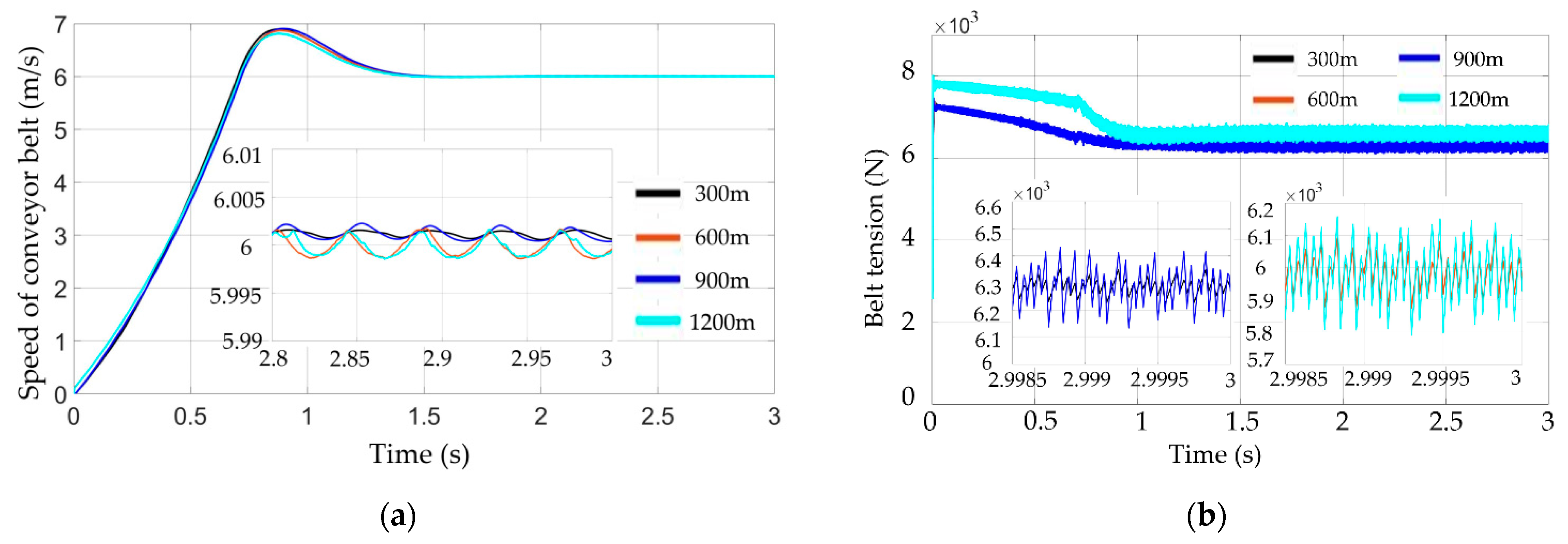
6.1. Simulation Comparison under Light Load Operation

Figure 9 shows the velocity and tension waveforms of each observation point on the conveyor belt of the traditional belt conveyor system under light load conditions. In Figure 9a, the fluctuation range of the conveyor belt speed is positively correlated with the distance of the conveyor belt observation point. At 3.7 s, the speed at the observation point 300 m reaches a maximum of 8.3 m/s. At 7.1 s, the speed at the observation point 300 m reaches a minimum of 5.32 m/s. At 20 s, the speed at the observation point 300 m reaches 6 m/s, and the traditional belt conveyor system enters a stable operation state. In Figure 9 b, at 1.61 s, the tension at each observation point reaches its peak, and the maximum tension at 1200 m is 15,060 N. When the conveying system is stable, the tension at the observation point of 1200 m reaches the maximum value of 11,910 N, and the tension increment is 5910 N.
The speed and electromagnetic torque curve of the driving motor of the traditional belt conveyor system under light load operating conditions is shown in Figure 10. The motor is started by the frequency converter. In the motor starting stage, the output electromagnetic torque is a peak of 22,000 N·m, and the speed rises rapidly. At 0.23 s, the motor speed reaches a peak of 69.81 r/min. At 15 s, the motor speed is basically stable at 60 r/min, and the electromagnetic torque fluctuates around 6000 N·m, ranging from 7200 N·m to 4100 N·m.
Figure 11 shows the speed and tension waveforms of each observation point on the conveyor belt of the distributed permanent magnet direct-drive belt conveyor system under the same light load condition. In Figure 11a, the speed change trend of each observation point during the start-up process is similar. Near 0.89 s, the speed of each observation point reaches the peak, with the maximum value of 6.9 m/s. At 3 s, the conveying system enters the steady-state operating state. In Figure 10b, the observation point 300 m and the observation point 900 m are located in the middle of the driving mechanism, and the tension changes of the two are close to the same, and finally stabilized at 6300 N; the observation point 600 m and 1200 m are located at the end of the driving mechanism, and the tension changes are consistent, and finally stabilized at 6000 N; this shows that there is good coordination and synchronization between the driving mechanisms in the permanent magnet direct-drive belt conveyor.
The comparison between Figure 9 and Figure 11 shows that after adding the permanent magnet motor with distributed drive to the conventional belt conveyor, the maximum value added of speed at the observation point 300 m is reduced by about 60.9%, and the maximum value of tension fluctuation is reduced by about 40.2%, which can effectively suppress conveying and shorten the start-up time by 85%, thus improving the production operation efficiency.
Figure 12 shows the speed and electromagnetic torque response curves of roller motors 2, 3, 4 and 5 of the distributed permanent magnet direct-drive belt conveyor system under light load operating conditions. At 0.88 s, the motor speed of each roller reaches a peak, with a maximum of 68.7 r/min. At 3 s, the speed of each roller motor is stable at around 60 r/min, the electromagnetic torque fluctuates around 600 N·m, and the fluctuation range is between 565 N·m and 640 N·m, which shows that the multi-motor ring coupling control strategy can meet the motor control requirements of distributed permanent magnet direct-drive belt conveyor.
Comparing Figure 10 and Figure 12 it can be seen that in the steady-state operation state, the output electromagnetic torque fluctuation range of the drive motor of the traditional belt conveyor is much larger than that of the distributed permanent magnet direct-drive belt conveyor. This shows that the output electromagnetic torque range of the drive motor of the traditional belt conveyor is large, but the control accuracy is low, and it is difficult to respond quickly and accurately.
In order to further analyze the tension variation waveform of each driving mechanism under steady-state operation, 640 m, 680 m, 720 m (front end of roller motor 6) and 720.5 m (back end of roller motor 6) are selected as observation points in the sixth group of driving mechanism. The tension waveform at the new observation points is shown in Figure 13.
In Figure 13, after the distributed permanent magnet direct-drive conveying system reaches a steady state, the tension of the conveyor belt in each group of driving mechanisms accumulates continuously along the conveying direction. At 3 s, the conveyor belt tension reaches a peak of 6600 N at the front end of the roller motor, and after the action of the roller motor, it drops to a valley value of 6000 N. For the entire permanent magnet direct-drive conveyor system, the maximum tension is at the front end of the roller motor of each set of drive mechanism, which is 6600 N, and the tension increment is 600 N, which is only 10.15% of the tension increment of the traditional belt conveyor.

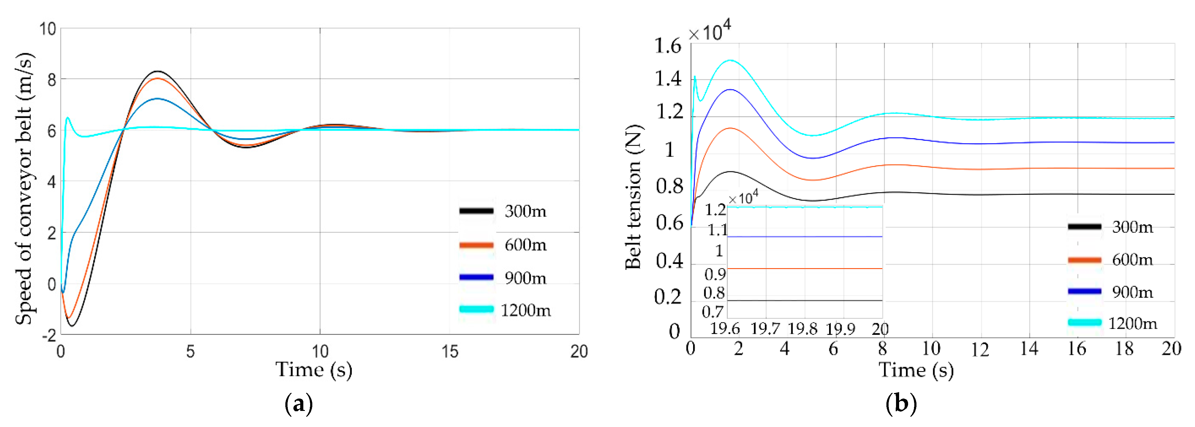
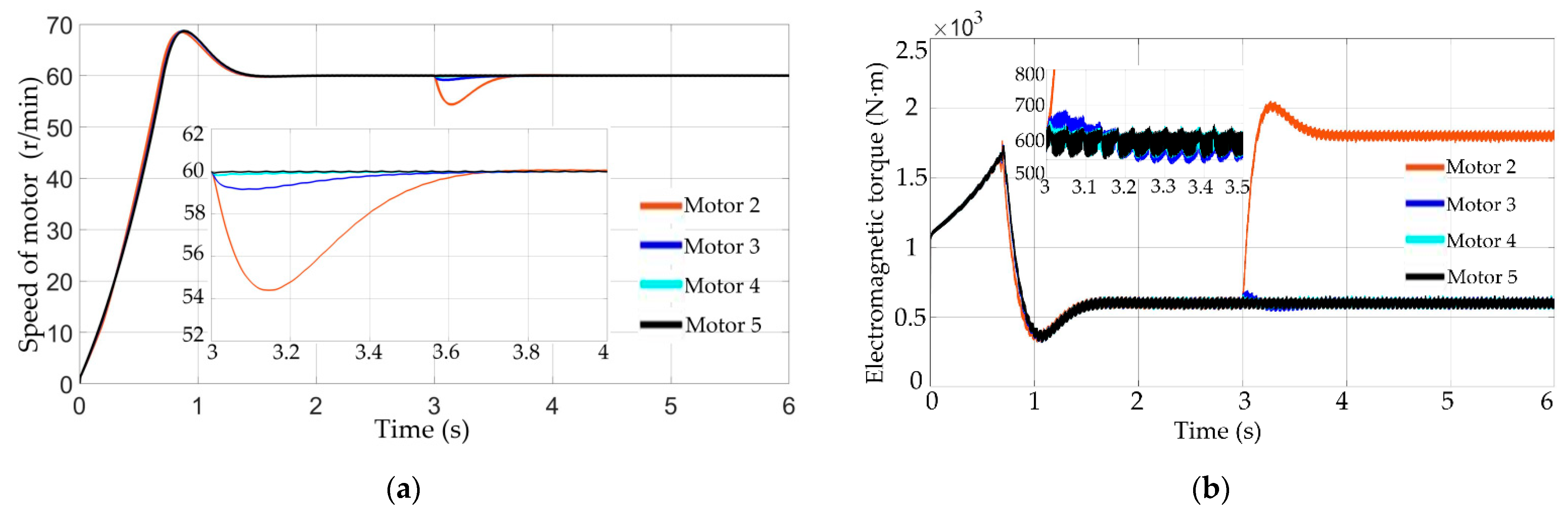
6.2. Simulation Comparison under Variable Load Operation

To further simulate the feed change process of the belt conveyor, at 20 s a heavy load is applied to the 120–240 m conveyor belt of the traditional belt conveyor. The resistance value of each conveyor belt unit on the 120–240 m conveyor belt has increased two-fold. The speed and tension waveforms of each observation point of the conveyor belt are shown in Figure 14. In Figure 14a, the conveyor belt speed between the observation point 300 m and the observation point 1200 m fluctuates. The velocity fluctuation is the largest at 300 m, the maximum value is 6.39 m/s, the minimum value is 4.66 m/s; at 45 s, the speed at the observation point of 300 m is stabilized again near the set value of 6 m/s, and the traditional belt conveyor system returns to the steady state.
In Figure 14b, the maximum value of tension fluctuation at 300 m observation points is 13,640 N, and finally stabilizes at 1310 N. The maximum value of tension fluctuation is 13,640 N at 1200 m of the observation point, and finally stabilizes at 13,100 N, which indicates that the sudden change of a certain load on the traditional belt conveyor will cause fluctuation to the whole conveying system.
Figure 15 is the speed and electromagnetic torque curve of the driving motor of the traditional belt conveyor system under variable load operation conditions. Drive motor speed fluctuation amplitude was between 59.76 r/min and 60.09 r/min, and the electromagnetic torque fluctuation between 8000 N·m and 7500 N·m eventually stabilized at around 7000 N·m, while dynamic adjustment time took nearly 10 s.
At 3 s, the distributed permanent magnet direct-drive belt conveyor suddenly adds the same load, the resistance values on each conveyor belt unit between 120–240 m (within the 2nd group drive mechanism) were increased by a factor of two. Figure 16 shows the speed and tension waveforms of each observation point of the conveyor belt. Observation point 300 m is the closest to the sudden load increase, the minimum speed at 300 m of the observation point is reduced to 5.64 m/s, and the peak value of tension fluctuation is 6680 N; at 6 s, the speed of observation point 300 m returns to the rated speed 6 m/s; observation point 600 m is separated from observation point 300 m by four roller motors, and the amplitude of belt tension fluctuation is weakened under the regulation of roller motors. At the observation point of 600 m, the speed is only reduced by 0.1 m/s near 3 s, and the tension fluctuation range is only increased to 6200 N. The tension fluctuation of the belt is weakened again by the adjustment of the roller motors, and it is difficult to observe the tension and speed fluctuation caused by the increased load at 900 m; 1200 m is also weakened by the roller motors, and it is almost not affected by the increased load locally.
Comparing Figure 14 and Figure 16, it can be seen that under the local load disturbance, the speed and tension variation amplitude of the distributed permanent magnet direct-drive belt conveyor is smaller than that of the traditional belt conveyor, and the fluctuation range of speed and tension is limited to a smaller range, which has better robustness.
Figure 17 is the speed and electromagnetic torque response curve of the idler motor 2, 3, 4 and 5 under the variable load condition of the distributed permanent magnet direct-drive belt conveyor system. In Figure 17a, the lowest speeds of the roller motors 2, 3, 4, and 5 are 54.4 r/min, 59.16 r/min, 59.87 r/min, and 59.93 r/min, respectively, indicating that the speed fluctuations of the conveyor belt can be further reduced under each motor adjustment. In Figure 17b, the maximum electromagnetic torque output of the idler motor 2 is 2040 N·m. Under the action of the ring coupling control strategy, the idler motors 3 and 4 rapidly increase the output value of their own electromagnetic torque and jointly reduce the tension fluctuation of the conveying system.
Comparing Figure 15 and Figure 17, it can be seen that the traditional belt conveyor drive motor has a limited adjustment range and cannot take into account the conveyor belt tension and speed fluctuations that are far away from the motor, which ultimately causes the traditional belt conveyor to take longer to achieve stability of the overall conveying system. In the distributed permanent magnet direct-drive belt conveyor, the distance between the roller motors is only 120 m, which can make a faster response to the load change of each link of the conveyor belt and greatly improve the anti-interference ability of the conveying system.

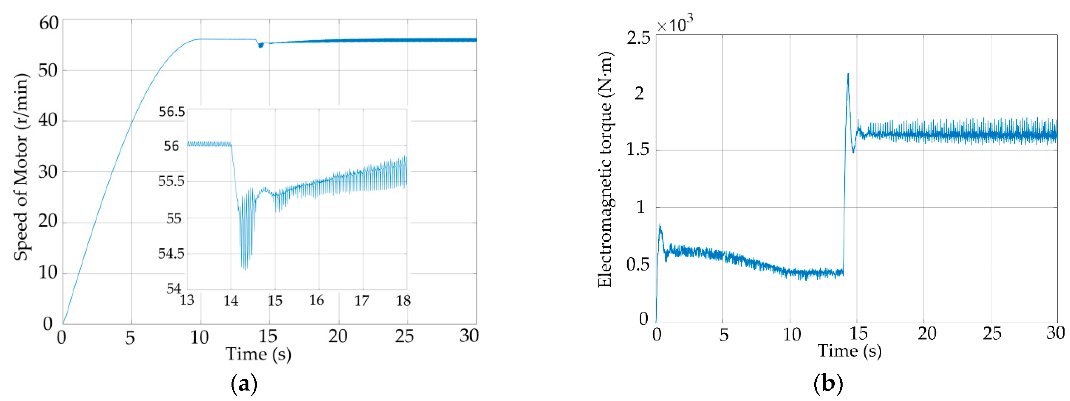
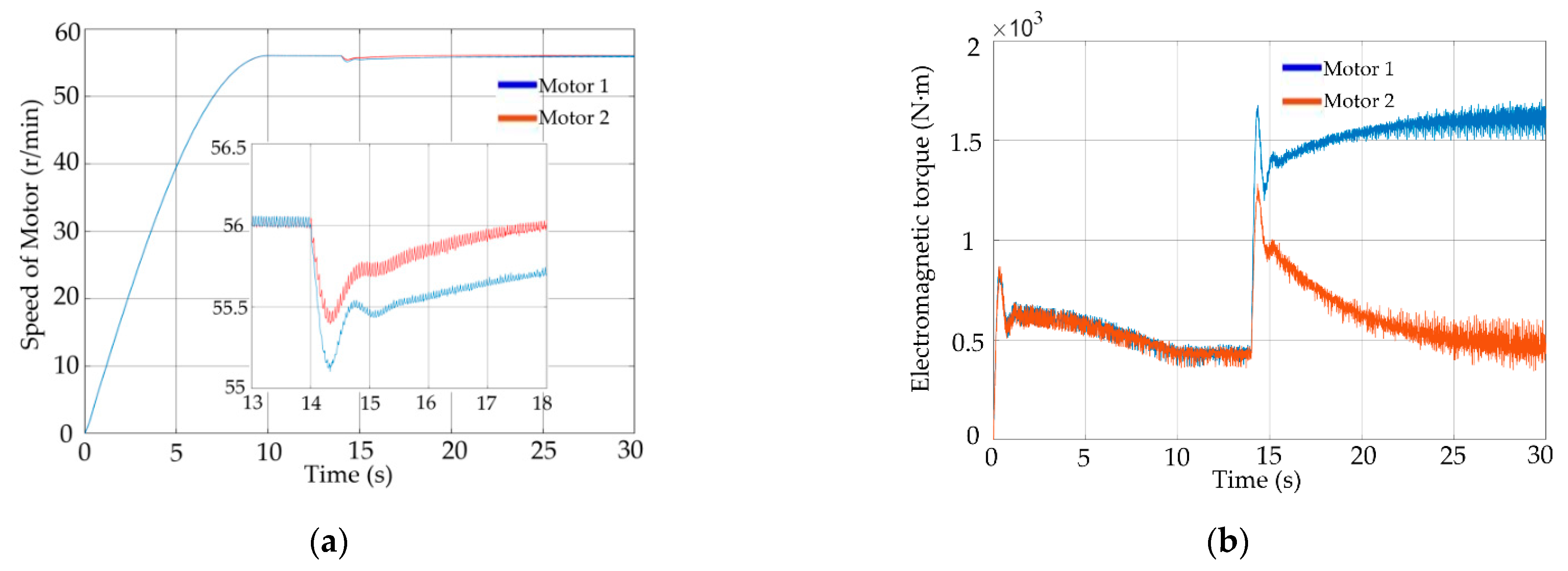
7. Experimental Verification

In order to verify the rationality of the electromechanical coupling model of the distributed permanent magnet direct-drive belt conveyor and the accuracy of the simulation results, this paper conducts experiments on the experimental platform of the belt conveyor shown in Figure 18. The experimental platform of the belt conveyor simulates the operation of different types of belt conveyors according to the number of driving motors of the belt conveyor. The belt conveyor is powered by a single permanent magnet synchronous motor to simulate the operation of the belt conveyor driven by the traditional single motor. The belt conveyor is powered by two permanent magnet synchronous motors as the roller motor to simulate the operation of the adjacent two driving mechanisms of the distributed permanent magnet direct-drive belt conveyor. The magnetic powder brake provides load resistance during the simulated operation.
The experimental platform of the belt conveyor controls the permanent magnet synchronous motor through the inverter to drive the conveyor belt to start and adjust the speed. In order to reduce the impact of the conveyor starting on the conveyor belt, the belt conveyor starts according to the sinusoidal speed curve during the experimental process, and the starting time is set to 12 s. During operation, the belt conveyor motor speed and electromagnetic torque will be real-time transmission to the upper computer. The parameters of the two permanent magnet synchronous motors are the same, and other specific parameters of the experimental platform are shown in Table 2.
The experimental platform to simulate the traditional belt conveyor running motor speed and electromagnetic torque curve is shown in Figure 19. The belt conveyor starts without load under the drive of the permanent magnet motor 1, and the permanent magnet motor 2 rotates with the conveyor belt, but does not provide electromagnetic torque. After the start-up process of the belt conveyor is completed, at 14 s, the magnetic powder brake provides load torque to the permanent magnet motor 1 to simulate the load mutation. At 10 s, the start-up phase of the belt conveyor is over, the speed of the permanent magnet motor 1 reaches the rated speed of 56 r/min and the electromagnetic torque tends to be stable to 400 N·m. When the load is suddenly applied at 14 s, the minimum speed of the permanent magnet motor 1 is reduced to about 54.2 r/min, and the electromagnetic torque is suddenly increased to a maximum of about 2230 N·m.
The experimental platform simulates the motor speed and electromagnetic torque curve of the two adjacent drive mechanisms of the distributed permanent magnet direct-drive belt conveyor as shown in Figure 20. The distribution of permanent magnet synchronous motors 1 and 2 represents the driving mechanism in the distributed permanent magnet direct-drive belt conveyor. The belt conveyor starts without load under the joint drive of permanent magnet synchronous motors 1 and 2. After the start-up process of the belt conveyor is completed, at 14 s, the magnetic powder brake provides the same load torque as that in Figure 19 to the permanent magnet synchronous motor 1 to simulate the load mutation on a driving mechanism.
At 10 s, the start-up phase of the belt conveyor is over, the speed of the permanent magnet synchronous motors 1 and 2 reaches the rated speed of 56 r/min, and the electromagnetic torque tends to be stable. After 14 s sudden load, the speed of permanent magnet synchronous motor 1 drops sharply, and the permanent magnet synchronous motor 2 improves its electromagnetic torque output according to the speed drop of the permanent magnet synchronous motor 1, so as to jointly reduce the impact of load mutation on the conveyor. After the permanent magnet synchronous motor 1 reaches a steady state again, the speed and electromagnetic torque of the permanent magnet synchronous motor 2 also return to the original steady state. The minimum speed of the permanent magnet synchronous motor 1 is reduced to about 55.1 r/min, and the electromagnetic torque is increased to about 1700 N·m.
The comparison between Figure 19 and Figure 20 shows that when the single motor driven belt conveyor suddenly increases the load, the motor speed is reduced by 1.8 r/min, and the electromagnetic torque is increased by 1830 N·m. The belt conveyor is driven by a permanent magnet motor on the original basis. After the same load is added to the original permanent magnet motor 1, the motor torque is reduced by 0.9 r/min, the speed reduction is reduced by 50.00%, the electromagnetic torque is increased by 1300 N·m and the electromagnetic torque is increased by 28.96%. Therefore, increasing the number of drive motors in the traditional belt conveyor can suppress the disturbance caused by local load changes. The distributed permanent magnet direct-drive belt conveyor has better dynamic adjustment performance than the single motor drive belt conveyor.

8. Conclusions

Aiming at the problems of excessive tension, speed and fluctuation in long-distance traditional single high-power motor centralized drive belt conveyors, a distributed permanent magnet direct-drive belt conveyor system is designed. A mechanical-electrical coupling dynamic model is built to study the control strategy and dynamic behavior. By comparing with the traditional belt conveyor, the following conclusions are obtained.
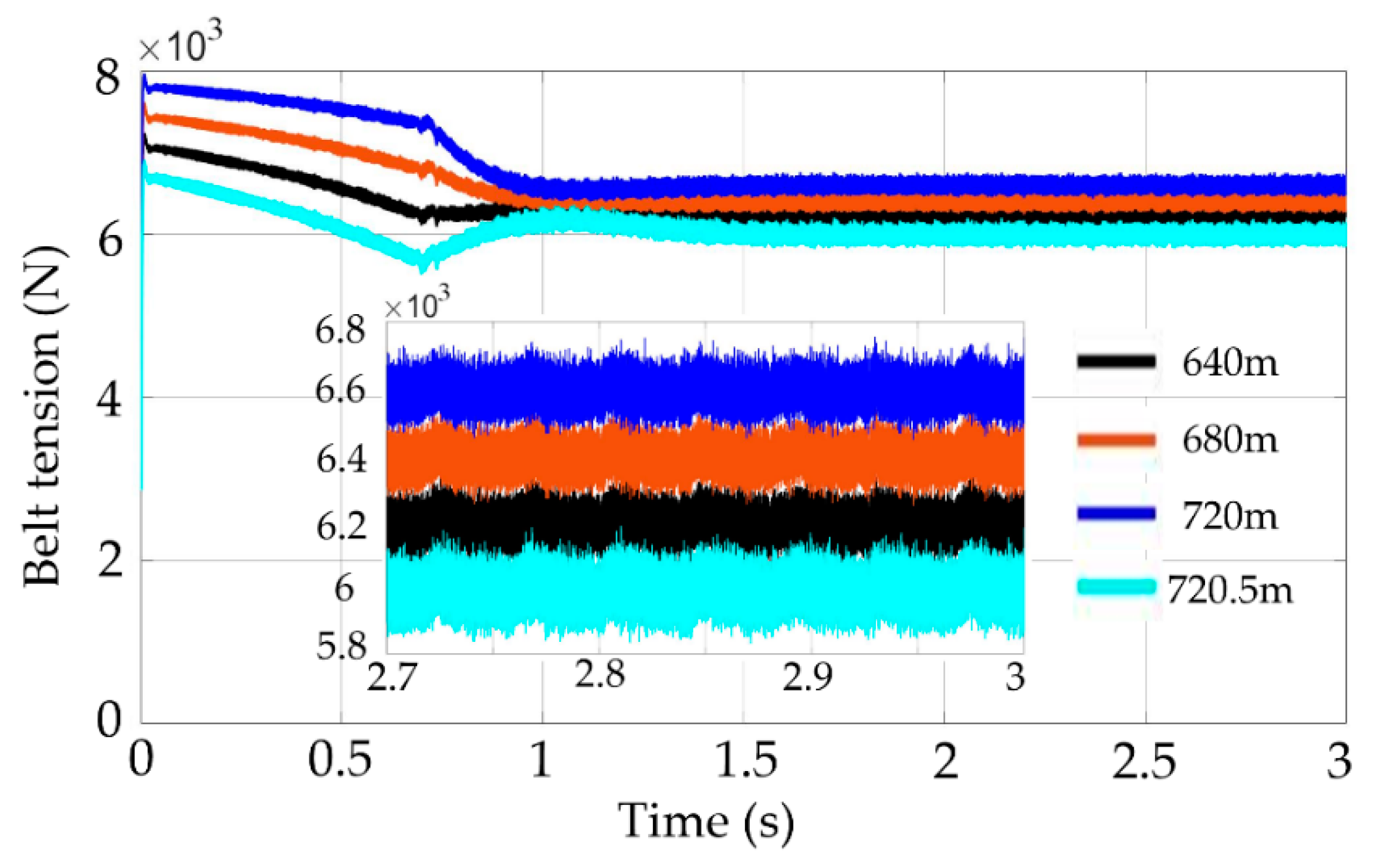
  • When the driving mechanism of the distributed permanent magnet direct-drive belt conveyor is in steady-state operation, the tension between each other will not accumulate with the transportation distance. The distributed permanent magnet direct-drive belt conveyor composed of N groups of driving units can reduce the tension increment of the bearing section of the traditional belt conveyor by N times.
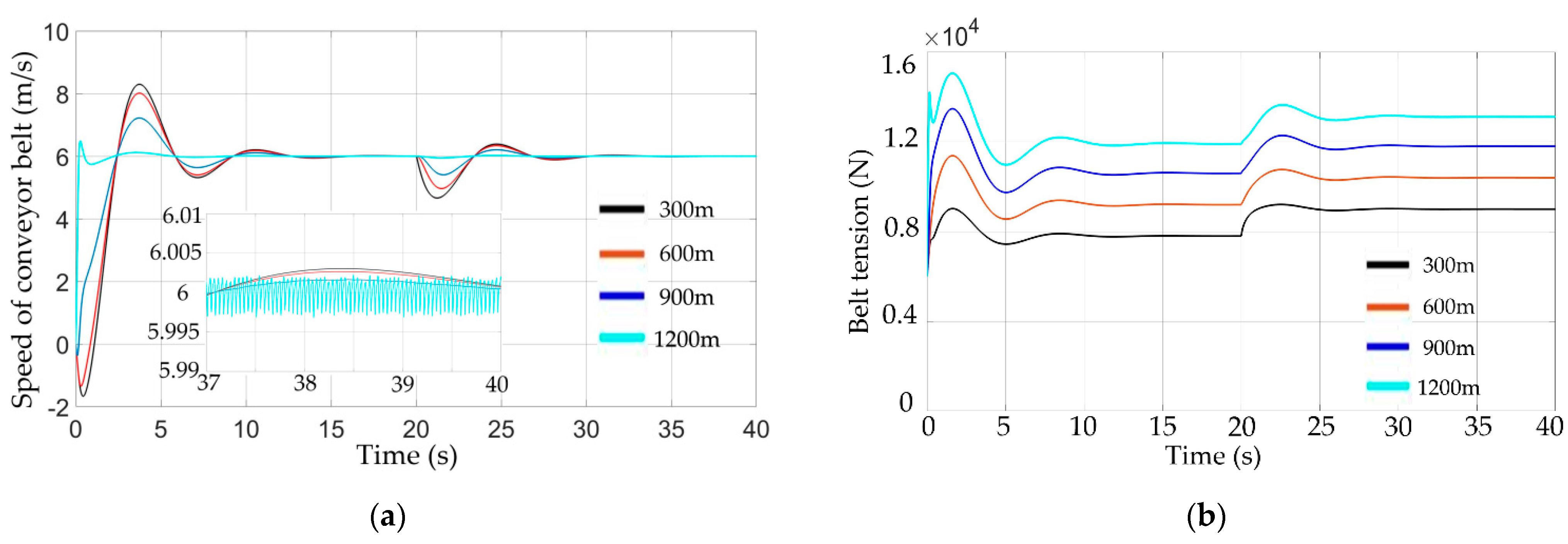
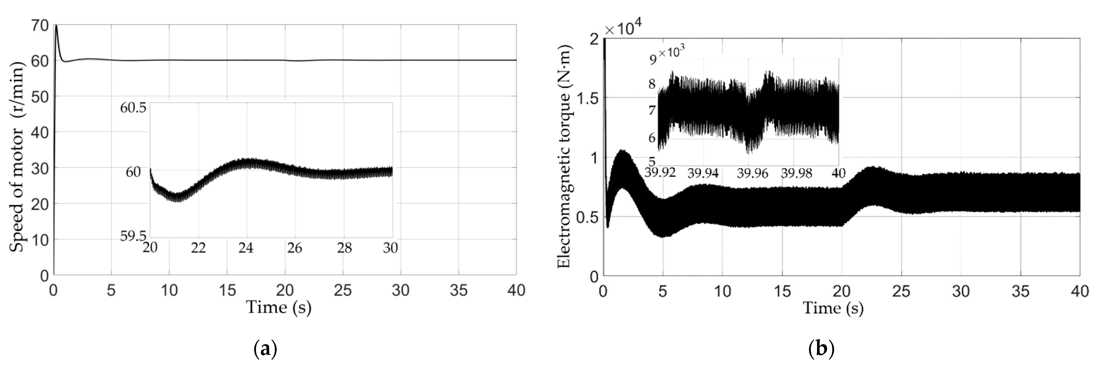
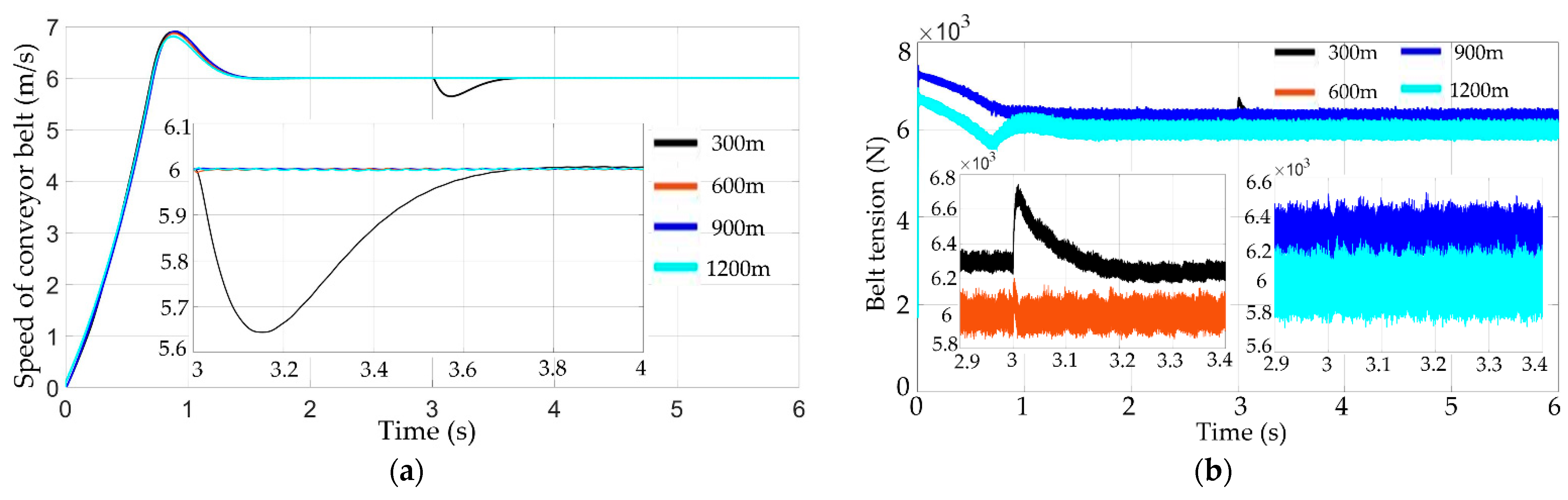
  • The distributed permanent magnet direct-drive control system based on multi-motor ring coupling control strategy and double sliding mode direct torque control strategy can perform the low speed and light load starting of the belt conveyor. Compared with the traditional belt conveyor, the distributed permanent magnet direct-drive belt conveyor has a shorter start-up time, the tension and speed fluctuation curves of the conveyor belt are closer, and the fluctuation amplitude is smaller, which has good dynamic characteristics and works efficiency.
  • When the local load fluctuates, the speed and tension of the whole traditional belt conveyor system will fluctuate, while the distance between the roller motors of the distributed permanent magnet direct-drive belt conveyor is smaller and the reaction is more rapid, which significantly reduces the influence range of local load disturbance and improves the robustness of the conveyor system.
  • The simulation experiments of the traditional belt conveyor and the distributed permanent magnet direct-drive conveyor under the same working conditions verify that the proposed new transportation technology can well suppress the accumulation of the tension increment and tension fluctuations, and the experiments proved that the distributed permanent magnet direct-drive belt conveyor has better dynamic regulation performance than the single motor-driven belt conveyor, which provides new methods and ideas for current modes of engineering transportation.

Author Contributions

Conceptualization, Q.Z. and G.D.; data curation, Q.Z. and H.G.; formal analysis, H.G.; funding acquisition, H.H.; investigation, Q.Z. and H.G.; methodology, Q.Z. and H.G.; project administration, Q.Z.; resources, Q.Z.; software, H.G.; supervision, G.D.; validation, Q.Z., G.D., Y.Z. and H.H.; visualization, H.G.; writing—original draft preparation, H.G.; writing—review and editing, Q.Z., H.G., G.D. and Y.Z. All authors have read and agreed to the published version of the manuscript.

Funding

This research was funded by National Nature Science Foundation of China, grant number 52177056, and Shaanxi Provincial Natural Science Basic Research Plan-Shaanxi Coal united foundation, grant number 2019JLM-51.

Data Availability Statement

Not applicable.

Conflicts of Interest

The authors declare no conflict of interest.

References

  1. Wang, J.H.; Yu, B.; Kang, H.P. Key technologies and equipment for a fully mechanized top-coal caving operation with a large mining height at ultra-thick coal seams. Int. J. Coal Sci. Technol. 2015, 2, 97–161. [Google Scholar] [CrossRef] [Green Version]
  2. Zhang, Y.L.; Wang, B.K.; Zhang, X.F.; Li, F.Q. Forty years’ development and future prospect on mechanized short-wallmining technology with continuous miner in China. J. China Coal Soc. 2021, 46, 86–99. [Google Scholar]
  3. Deng, Y.X.; Yang, M.; Liu, Y.J.; Wang, Z.; Chen, C.L.P. Adaptive fuzzy tracking control for uncertain nonlinear systems with multiple actuators and sensors faults. IEEE Trans. Fuzzy Syst. 2022. [Google Scholar] [CrossRef]
  4. Zeng, F.; Yan, C.; Wu, Q. Dynamic behaviour of a conveyor belt considering non-uniform bulk material distribution for speed control. Appled Sci. 2020, 10, 4436. [Google Scholar] [CrossRef]
  5. He, D.J.; Pang, Y.S.; Lodewijks, G. Healthy speed control of belt conveyors on conveying bulk materials. Powder Technol. 2018, 327, 408–419. [Google Scholar] [CrossRef]
  6. Wang, Y.Y.; Bao, J.S.; Ge, S.R.; Yin, Y.; Wang, S.B.; Zhang, L. Simulation and experimental study on electromechanical coupling model of permanent magnet direct drive system for scraper conveyor. J. China Coal Soc. 2020, 45, 2127–2139. [Google Scholar]
  7. Jia, L.; Deng, X.L.; Wen, G.X.; Li, L.; Wang, Z.; Chen, C.L.P. Game-Based Backstepping Design for Strict-Feedback Nonlinear Multi-Agent Systems Based on Reinforcement Learning. IEEE Trans. Neural Netw. Learn. Syst. 2022. [Google Scholar] [CrossRef]
  8. Zhang, L.; Bao, J.S.; Ge, S.R.; Yang, X.L.; Yin, Y.; Bao, Z.Y. Permanent magnet driving technology and its application status in the field of mining equipment. Coal Sci. Technol. 2022, 50, 275–285. [Google Scholar]
  9. Semenov, D.; Bing, T.; Li, S. Advanced fault-tolerant current control of five-phase PMSM for mining applications. In Proceedings of the IEEE Applications Society Meeting, Atlanta, GA, USA, 10–14 June 2016; pp. 1–7. [Google Scholar]
  10. Semykina, I.; Tarnetskaya, A.; Tyulenev, M. Magnet synchronous machine of mine belt conveyor gearless drum-motor. In E3S Web Conferences; EDP Sciences: Les Ulis, France, 2018; Volume 41, pp. 1–6. [Google Scholar]
  11. Wang, D.L.; Wang, R.F.; Lai, C.L. Design of dual-motor driving control system of belt conveyor. Ind. Mine Autom. 2018, 44, 74–78. [Google Scholar]
  12. Yang, C.Y.; Liu, J.H.; Li, H.; Zhou, L.N. Energy modeling and parameter identification of dual-notor-driven belt conveyors without speed sensors. Energies 2018, 11, 3313. [Google Scholar] [CrossRef] [Green Version]
  13. Yang, X.L.; Ge, S.R.; Zu, H.B.; Bao, J.S.; Chang, G.Q.; Zhang, L.; Li, H.Y. Permanent magnet intelligent drive system and control straegy of belt conveyor. J. China Coal Soc. 2020, 45, 2116–2126. [Google Scholar]
  14. He, B.Y.; Sun, Y.H.; Nie, R.; Li, G.P. Dynamic behavior analysis on the ring chain transmission system of an armoured face coveyor. J. Mech. Eng. 2012, 48, 50–56. [Google Scholar] [CrossRef]
  15. Yao, Y.P.; Zhang, B.S. Influence of the elastic modulus of a conveyor belt on the power allocation of multi-drive conveyors. PLoS ONE 2020, 15, e0235768. [Google Scholar] [CrossRef] [PubMed]
  16. He, D.J.; Pang, Y.; Gabriel, L. Green operations of belt conveyors by means of speed control. Appl. Energy 2017, 188, 330–341. [Google Scholar] [CrossRef]
  17. Witold, K.; Natalia, S.; Martyna, K.; Robert, K. Specific Energy Consumption of a Belt Conveyor System in a Continuous Surface Mine. Energies 2020, 13, 5214. [Google Scholar]
  18. Zhang, S.R.; Xia, X.H. Modeling and energy efficiency optimization of belt conveyors. Appl. Energy 2010, 88, 3061–3071. [Google Scholar] [CrossRef]
  19. Michael, J.C.; Craig, A.W.; Peter, W.R.; Bin, C. Reducing the energy intensity of overland conveying using a novel rail-running conveyor system. Int. J. Min. Reclam. Environ. 2020, 35, 183–198. [Google Scholar]
  20. Ye, Y.H.; Peng, F.; Huang, Y.K. Overview of multi-motor synchronous motion control technology. Trans. China Electrotech. Soc. 2021, 36, 2922–2935. [Google Scholar]
  21. Vedrana, J.S.; Toni, V.; Tin, B.; Marinko, B. A survey of fuzzy algorithms used in multi-motor systems control. Electronics 2022, 9, 1788. [Google Scholar]
Figure 1. Structure diagram of a distributed permanent magnet direct-drive belt conveyor.
Energies 15 08699 g001
Figure 2. Dynamic model of conveyor belt unit i.
Energies 15 08699 g002
Figure 3. Dynamic model of roller motor n.
Energies 15 08699 g003
Figure 4. Direct torque controller block diagram based on double sliding mode control.
Energies 15 08699 g004
Figure 5. Logic block diagram of multi-motor ring coupling control strategy.
Energies 15 08699 g005
Figure 6. Discrete element model of mechanical load dynamics for distributed permanent magnet direct drive belt conveyor.
Energies 15 08699 g006
Figure 7. Electromechanical coupling model of distributed permanent magnet direct-drive belt conveyor.
Energies 15 08699 g007
Figure 8. Distribution of observation points on the distributed permanent magnet direct-drive belt conveyor.
Energies 15 08699 g008
Figure 9. Conveyor belt response curve of traditional belt conveyor system under light load operation condition. (a) Velocity curve; (b) Tension curve.
Energies 15 08699 g009
Figure 10. Response curve of driving motor of traditional belt conveyor system under light load. (a) Speed curve. (b) Electromagnetic torque curve.
Energies 15 08699 g010
Figure 11. Conveyor belt response curve of distributed permanent magnet direct-drive belt conveyor system under light load operation condition. (a) Velocity curve; (b) Tension curve.
Energies 15 08699 g011
Figure 12. The response curve of the roller motor of the distributed permanent magnet direct-drive belt conveyor system under light load operating conditions. (a) Speed curve; (b) Electromagnetic torque curve.
Energies 15 08699 g012
Figure 13. Conveyor belt tension waveform diagram on the 6 group of driving mechanism under light load operating conditions.
Energies 15 08699 g013
Figure 14. The response curve of conveyor belt on traditional belt conveyor system under variable load operation conditions. (a) Velocity curve; (b) Tension curve.
Energies 15 08699 g014
Figure 15. Response curve of driving motor of traditional belt conveyor system under variable load operation conditions. (a) Speed curve; (b) Electromagnetic torque curve.
Energies 15 08699 g015
Figure 16. The response curve of conveyor belt on distributed permanent magnet direct-drive belt conveyor under variable load operation conditions. (a) Velocity curve; (b) Tension curve.
Energies 15 08699 g016
Figure 17. Response curve of roller motor of distributed permanent magnet direct-drive belt conveyor system under variable load operation conditions. (a) Speed curve; (b) Electromagnetic torque curve.
Energies 15 08699 g017
Figure 18. Experimental platform of the belt conveyor.
Energies 15 08699 g018
Figure 19. The curve of motor speed and electromagnetic torque of traditional belt conveyor. (a) Speed curve; (b) Electromagnetic torque curve.
Energies 15 08699 g019
Figure 20. The curves of motor speed and electromagnetic torque of two adjacent driving mechanisms of distributed permanent magnet direct-drive belt conveyor. (a) Speed curve; (b) Electromagnetic torque curve.
Energies 15 08699 g020
Table 1. Motor parameters.
ParameterValue of Drive Motor Value of Roller Motor
Rated power (kW)144.512.6
Rated speed (r/min)6060
Rated torque (N·m)23,0002000
Rotor inertia (kg·m2)5610
Table 2. Specific parameters of experimental platform for the belt conveyor.
ParameterValueParameterValue
Length of conveyor (m)2Rated power of motor (kW)22
Rated speed of conveyor (m/s)2.5Rated speed of motor (r/min) 56
Belt width (m)1Rated frequency of motor (Hz)14
Diameter of motor (m)0.5Rated torque of brake (N·m)2000
Publisher’s Note: MDPI stays neutral with regard to jurisdictional claims in published maps and institutional affiliations.

