1. Introduction
Inductive power transfer (IPT) enables energy transfer without a metal contact interface from the source to the load [
1]. The concept of convenience due to the advancement of wireless charging technologies has been expanded beyond making the electric vehicle (EV) charging process much easier. Keeping the customer safe while charging EVs is also a major factor for the growth of IPT [
2]. IPT based wireless chargers can eliminate unnecessary plugins and avoid the safety issue caused by a cable-based charger device [
3]. More importantly, IPT is commonly used in an environment that requires avoiding sparks such as petrol stations and cleanrooms, which is considered important for the future EV charging industry.
The power transmission efficiency of IPT wireless chargers is significantly affected by the distance between the transmitter and the receiver [
4]. To improve the efficiency of energy transmission in the IPT system, resonant compensation topologies composed of inductors and capacitors are required for the loosely coupled transformer (LCT) [
5]. According to the series or parallel connections of inductors and capacitors, resonant topologies can be classified into four categories: series-series (SS) [
6,
7], series-parallel (SP) [
8], parallel-series (PS) [
9], and parallel-parallel (PP) [
10]. The SS resonant topology can show high efficiency in the CV mode whereas SP resonant topology can achieve a better performance in CC mode [
11]. Moreover, some structures such as LLC [
12] and LCC [
13] are used to avoid damage to the inductors and capacitors caused by overvoltage, which can be placed on the primary side and the secondary side [
14].
Several open-loop control methods for hybrid resonant circuits have been introduced for the CC-CV output requirement and aim to reduce the controller complexity [
15,
16,
17,
18]. The resonant circuit can be changed using bidirectional switches that have T and π modes to adaptively match with CC or CV mode under specific conditions [
15]. This hybrid structure can be configured on the primary side [
16] or the secondary side. Typically, the hybrid structure is considered on the secondary side to reduce the requirement of wireless feedback by most of the literature [
15]. The non-ideal property of the parasitic components and forward voltage drops leads to a significant difference between the theoretical analysis and the practical implementation of the hybrid structure. Moreover, in an open-loop control structure, the drift of the charging voltage and current during the charging process may reduce the actual charged power or damage the battery due to overcharging [
19]. It is essential to develop a closed-loop control structure for IPT chargers to avoid these issues [
20,
21].
To achieve the closed-loop control, the design for IPT is more complex than the traditional converter as the power source of the primary side and the battery of the secondary side are physically isolated. Hence, it is necessary to develop a closed-loop control structure with wireless communication technology for transmitting and receiving the feedback signals during the charging process [
22]. One of the important issues of controller design is stability consideration. There were several studies proposed to analyze and enhance the system’s robustness and stability [
23,
24,
25,
26]. For example, a new small-signal analysis for a DC-DC converter with variable input and constant output has been proposed [
23]. Wireless communication technologies such as power line carriers [
27] and radio frequency (RF) [
28] can be leveraged to transmit the feedback signal of the closed-loop control. However, it can be easily interfered by electromagnetic interference (EMI), which is caused by the electromagnetic field from the LCT or other electromagnetic signals with near frequency [
29]. IR wireless communication is the optical communication technology. Optical signals would not be disturbed by electromagnetic signals. Moreover, the security of the IR communication is better because of the orientation limit between the transceiver and receiver [
30].
Moreover, the transition from CC to CV mode is controlled by multiple bidirectional switches. The MOSFET-based bidirectional switch can shorten the transition time from CC to CV mode [
31]. However, the total conduction loss produced by this switch can be larger than the electromechanical relay-based bidirectional switch [
32]. It is also much easier to design the driver circuit for the electromechanical relay-based bidirectional switch than for the MOSFET-based one [
31].
In this paper, the output drift phenomenon in practice was investigated through the experimental results and a closed-loop controller based on IR wireless communication was proposed for the hybrid IPT charger. A full-bridge inverter with phase-shift control was used to provide the AC voltage to the resonant components and transceiver coil. The required phase-shifted angle was calculated according to the battery status at the secondary side and transmitted to the primary side via IR communication. The main contributions of this paper can be summarized as follows:
(1) To address the voltage drift issue present in hybrid IPT architectures that use the simplified open-loop control strategy, a closed-loop control architecture is introduced. The voltage of the DC/AC converter is controlled by the phase-shift method [
33,
34,
35]. Importantly, the required phase-shifted angle determined by the voltage and the current of the battery is computed at the secondary side and then transmitted to the primary side controller through IR wireless communication. In this case, the voltage during CV mode is not going to exceed the maximum voltage, which causes the overvoltage problem.
(2) IR is used as a wireless communication medium to carry feedback signals that can avoid the inference caused by EMI from the LCT. Furthermore, the transmitted data are not easily leaked because of the optical orientation limit, which would enhance the data security. The required phase-shifted angle was directly calculated by the microcontroller at the secondary side according to the battery voltage and current. Compared with transmitting two sets of voltage and current data, transmitting only one set of angle data can greatly reduce the time delay caused by data transmission.
The rest of the paper is organized as follows. In
Section 2, the hybrid IPT charger with an IR communication-based feedback controller is introduced. The circuit characteristics under open-loop control are discussed in
Section 3. In
Section 4, IR is introduced as a wireless communication medium to transmit feedback signals for close-loop control. The related experiment results and the discussion is detailed in
Section 5.
2. System Configuration of Hybrid IPT
The system configuration of the proposed IPT charger is shown in
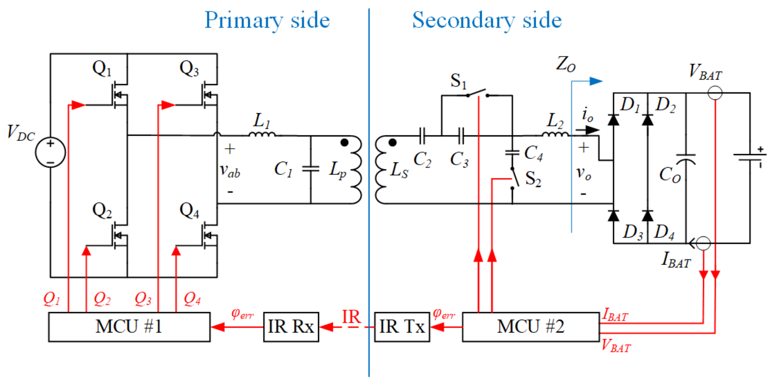
Figure 1. The DC resource for the LCL resonant inverter circuit comes from the AC mains through a power factor corrector. To facilitate the CC-CV charging profile, a hybrid resonant circuit was employed on the secondary side of the IPT with a full-wave rectifier. Two bidirectional switches with associated capacitors were introduced to change the topology of the resonant circuit.
Two microcontroller units (MCUs) were used in the proposed closed-loop control architecture. The MCU on the primary side (MCU #1) was used to provide phase-shift control signals for the active full-bridge inverter according to the received information transferred from the secondary side via IR communication. The MCU on the secondary side (MCU #2) was used to sample the battery charging current and voltage as well as control the two bidirectional switches. The required shifted-angle of the primary inverter would also be determined and transferred to the primary side via IR communication.
The common CC/CV charging method was used in the proposed IPT charger. The two bidirectional switches would be turned on or off for the CC or CV charging mode, as shown in
Figure 1. For charging the battery in CC mode, the switches S
1 and S
2 are both turned on. Here, capacitor C
3 is bypassed, and capacitor C
4 is integrated into the compensation circuit. With this resonant compensation circuit, the charger would be able to provide a nearly constant output current, theoretically.
Once the battery voltage is increased to the rated charging voltage VBAT,Max, the switches S1 and S2 will both be turned off to change the charger into the CV charging mode. The capacitor C4 is open-circuited, and the capacitor C3 would then be integrated into the resonant compensation circuit. Theoretically, the charger in this operation mode would be able to provide a nearly constant output voltage.
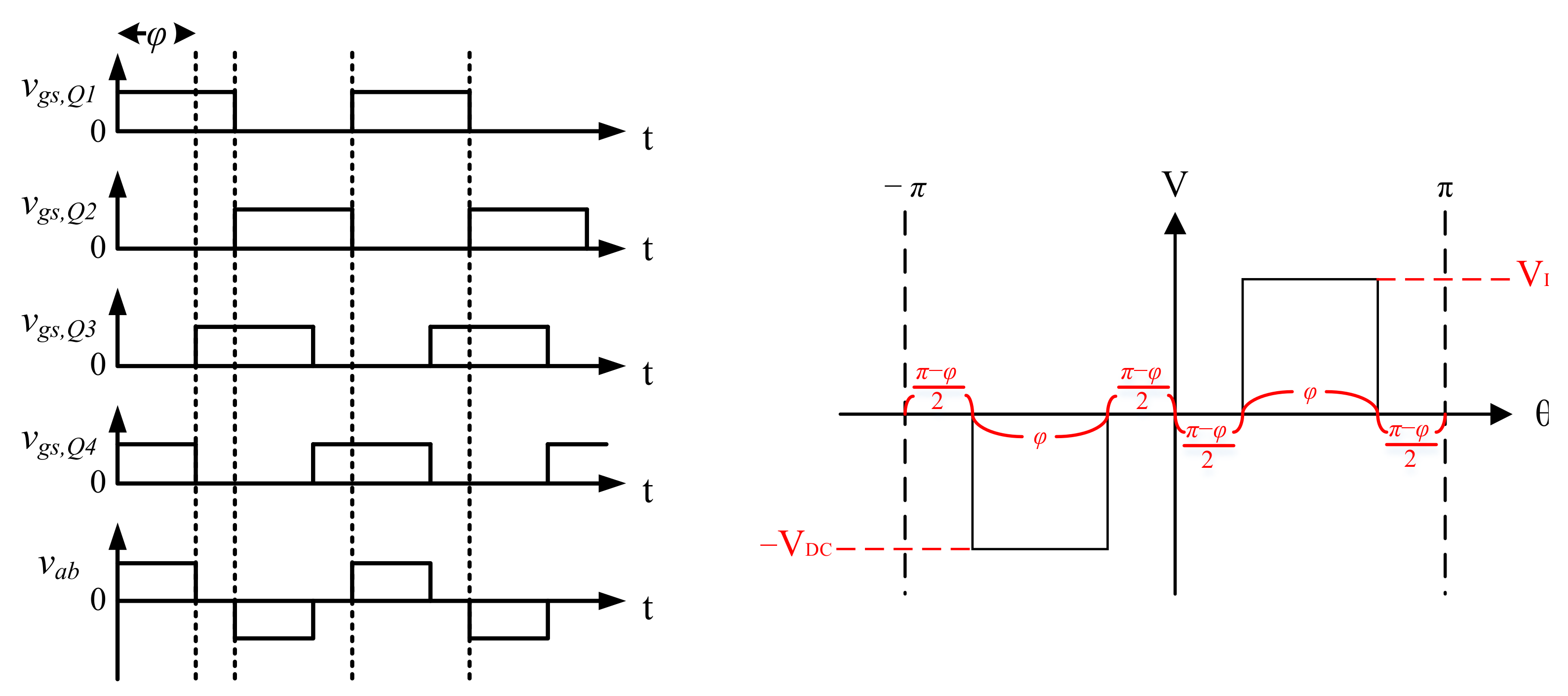
The control signals for the four active switches Q
i (
i = 1, 2, 3, 4) of the inverter on the primary side and the output of the high-frequency voltage
vab are shown in
Figure 2, where
φ is represented as the phase-shifted angle. The angular frequency of
vab is defined as
ω. Specifically, the control signals for the switch pair Q
1/Q
2 (or Q
3/Q
4) in one leg are complementary. The voltage analyzed
vab in
Figure 2 can be given as:
According to the Fourier transform, the output voltage
vab is given as:
where
a0 and
an are 0, and only the fundamental component is considered (
n = 0). The amplitude of the inverter output voltage
vab is represented as
Vab and can be determined by Equation (3).
where V
DC is represented as the input DC voltage. The amplitude of the voltage applied into the inductive power transferring circuit can be controlled by adjusting the phase-shifted angle.
According to the operation principles analyzed in [
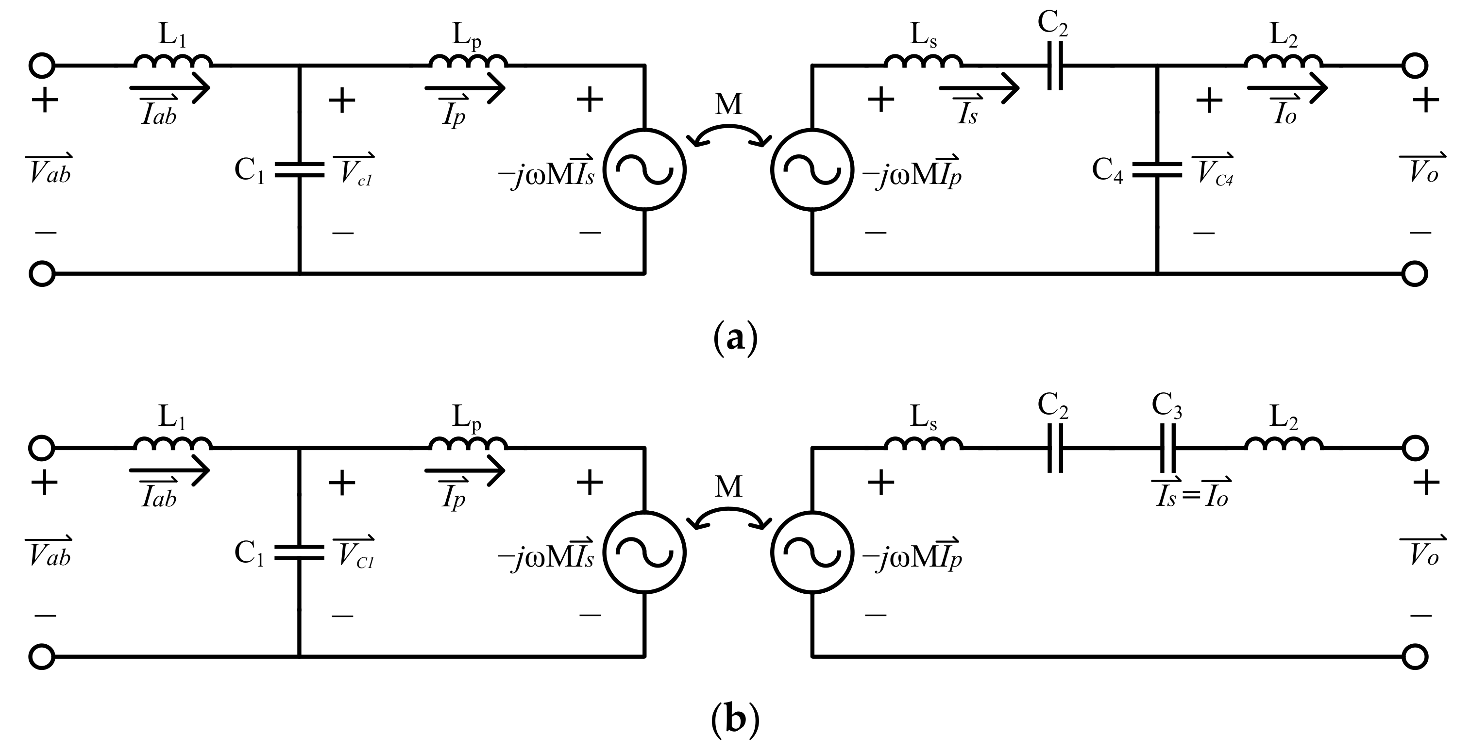
14], the switching frequency of the inverter should be equal to the resonant frequency of the compensation circuit to achieve the proper equivalent impedance. In
Figure 2, the equivalent circuit operating in CC mode and CV mode is given, where the equivalent impedance of the diode bridge, output capacitor, and batteries is denoted as
Zo. While the charger is operated with a resonant frequency and the switches S
1 and S
2 are turned on, the charger is operated in the CC mode. The analysis of the circuit in
Figure 3a is given as:
where the vector of the input parameter of the resonant compensated circuit is derived.
The design of capacitance C
3 is equal to C
4/2 while the resonant frequency of the compensation circuits is expressed as Equation (6).
Under the condition of the resonant frequency, Equations (4) and (5) can be sorted as follows:
According to Equation (8), it can be concluded that there is a proportional relationship between the secondary side output current and the primary side input voltage, which means that when the input voltage is fixed, the output is a stable current source, and the corresponding equivalent battery charging current can be expressed as Equation (9)
where
IO, peak is represented as the peak value of the current
io shown in
Figure 1, and M is represented as the mutual inductance of the LCT. From Equation (9), it can be seen that the battery charging current is independent of the output power.
Once switches S
1 and S
2 are turned off for the CV mode, the charger is changed to provide the CV outputs for the battery. A similar analysis of the output performance under CV mode, which is shown in
Figure 3b, is listed as follows:
Under the resonant circuit, the vector of the current and the voltage can be sorted as follows:
According to Equation (13), the relation between the output voltage and the input voltage can be derived. Hence, the charging voltage
VBAT is determined as Equation (14) and is independent of the output power.
where
VO, peak is represented as the peak value of the voltage
vo shown in
Figure 1. Basically, in the CC and CV modes, the charging current and voltage can be adjusted by tuning the shifted-angle of the primary side inverter.
From Equations (9) and (14), it can be seen that the charger can theoretically provide stable CC-CV output for batteries. The ideal output current and voltage expressions are both related to the phase-shifted angle. However, the parasitic elements and stray impendence of the components that appear in the practical implementation are not considered in these equations. Thus, the output voltage and current will be different from the theoretically determined values.
3. Circuit Characteristics under Open-Loop Control
To investigate the variance of the charging current and voltage from the phase-shifted angle in a practical experiment, an IPT charger with a 600 W rated output power and a hybrid compensation circuit were implemented in this study. For a common 48 V battery pack, the proposed charger can provide a maximum 10 A charging capability. Experiments of 57.8 V constant charging voltage and 10 A constant charging current were carried out, respectively. Different constant load resistances were used to simulate the battery charging load [
36].
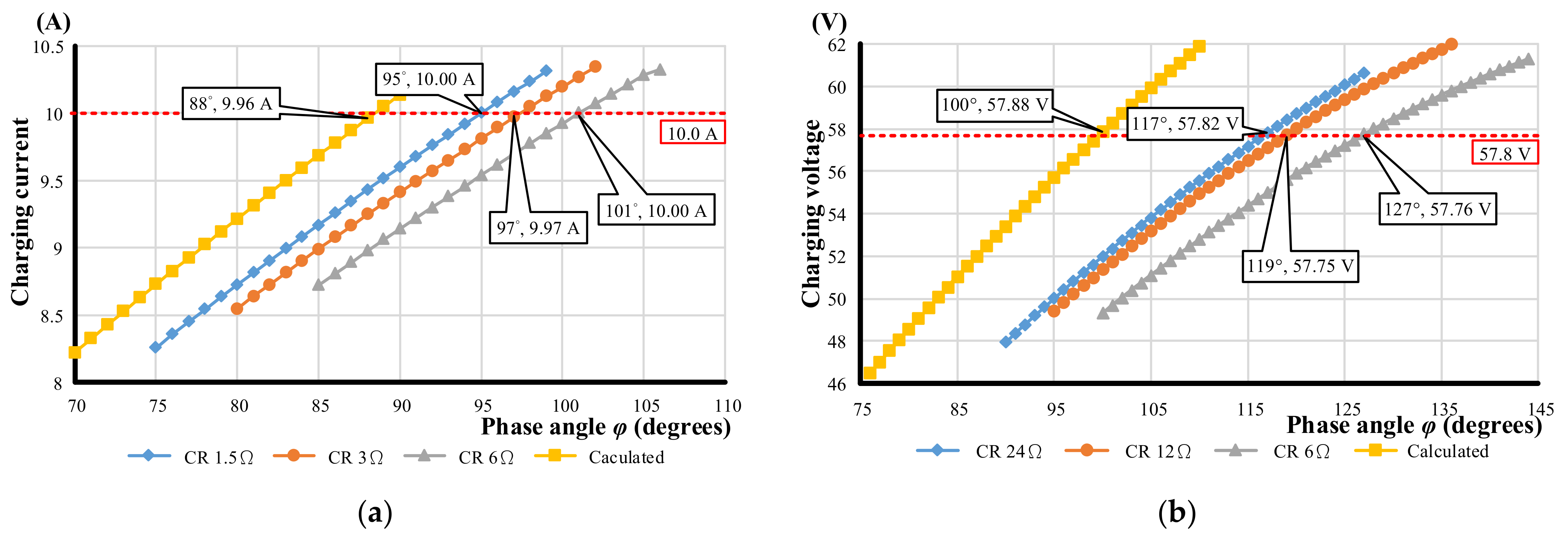
The calculated results from Equations (9) and (14) were carried out, and the experimental setup operated under open-loop control and constant resistance (CR) mode. The phase-shifted angle was tuned to reach the regulated current in CC mode or the voltage in CV mode to verify the function. To verify the prototype under open-loop condition, the resistance was chosen at 1.5 Ω, 3 Ω, and 6 Ω under CC mode, and the resistance was chosen at 6 Ω, 12 Ω, and 24 Ω under CV mode. In
Figure 4a, it can be seen that to maintain a constant charging current while the charging power is increased, the phase-shifted angle should also be increased. In
Figure 4b, the phase-shifted angle will be reduced to maintain a constant output voltage, thus avoiding the battery voltage increasing continuously under CV mode. From the open-loop experimental results shown in
Figure 4, it can be seen that to remain a constant charging current and voltage, there will be an angle variation of about 4° in CC mode and 10° in CV mode. Therefore, in a practical implementation of a hybrid compensated IPT charger, MCUs are required to achieve the closed-loop control by adjusting the phase-shifted angle to regulate the charging voltage and current.
In this paper, an auxiliary closed-loop controller with IR wireless communication was proposed for the IPT charger to solve the issue with variations in the voltage and current from the desired values under open-loop control. MCU #2 will determine the adjustment of the phase-shifted angle according to the battery charging current and voltage. The information on adjusting the phase-shifted angle will then be transferred to the MCU #1 side via the IR communication interface. The control signals for the inverter were generated by MCU #1 based on the received information from the secondary side. As a result, the IPT charger will be able to provide a more accurate and stable charging current and charging voltage for the battery.
4. Infrared Feedback Signal Transmission Protocol and Feedback
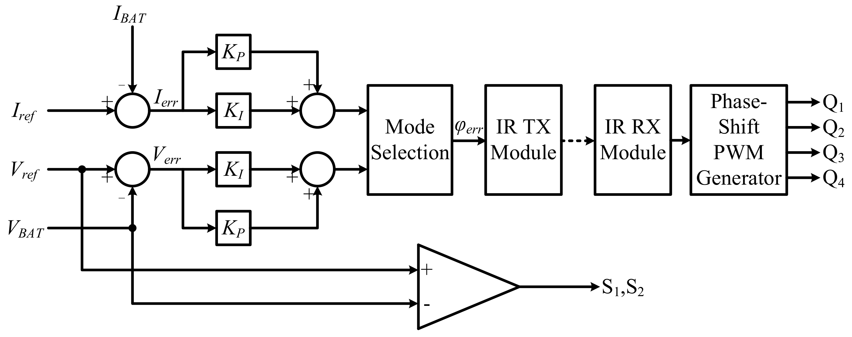
To fulfill the charging requirement in the charging process, the closed-loop control scheme is shown in
Figure 5. The sensed charging voltage and current were compared with the reference value to determine the error signals,
Ierr and
Verr. The error signals were fed to the proportional-integral (PI) controllers to determine the corresponding phase error
φerr. These data were then transmitted to the primary side and a new phase-shifted angle was adjusted by MCU #1 via the received angle from the secondary side. Accordingly, the phase-shifted PWM signals of the inverter were also generated. The control signals of the bidirectional switches S
1,
2 were also determined by MCU #2 according to the comparison between the reference voltage and charging voltage.
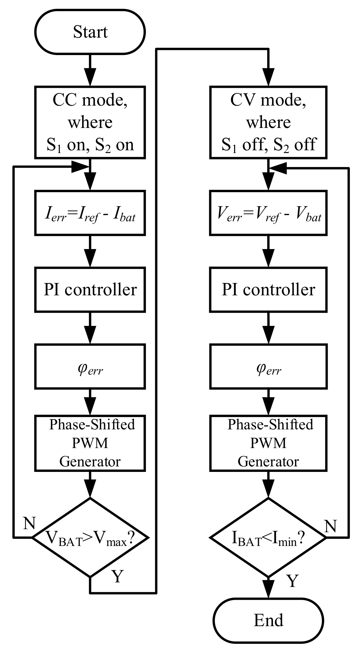
The control flowchart with CC-CV mode selection and phase-shifted angle is shown in
Figure 6. While in CC mode, the two switches S
1,2 were turned on and the phase error
φerr was determined by the current error and PI controller. Once the battery pack voltage was increased to the maximum charging voltage
Vmax, the charger switched into CV mode and the two switches S
1,2 were turned off. Then, the phase error
φerr was determined by the voltage error and PI controller. Finally, while the charging current in the CV mode was lower than the preset minimum charging current
Imin, the whole charging procedure was then finished.
IR communication is a serial data transmission technology, which means that the required transmission time will increase with the number of data bits. Therefore, the dynamic response will be affected by the data transmission time. According to the protocol, the longest time of transmission a byte of data took was 14.2 ms. If the charging current and voltage are both sampled and transferred into two 10-bits data, the total transmission time to the primary side would take 28.6 ms. Hence, to reduce the required transmission time, which will facilitate a faster control response, the required phase-shifted angle was calculated from the charging voltage and current in MCU #2, as shown in
Figure 5.
From the open-loop experimental results in
Figure 4, to achieve the battery charging requirement, the range of phase-shifted angle
φ was between about 97° and 127°. In this paper, a 16-bit microchip microcontroller dsPIC30F4011, which is common in the market, was chosen to implement the hybrid IPT charger with an IR closed-loop controller. The resolution for adjusting the
φ was determined by the timer of the PWM module in the MCU. From the open-loop test in
Figure 4a,b, the range of the
φ was narrowed to 31°, which means that 8 bits of data are affordable to present the correct
φ value. The comparison between the proposed feedback transmission method and the common strategies with two 10-bit data is shown in
Table 1. Due to the transmission being changed from transmitting the charging voltage and current to
φerr, the amount of feedback data was reduced from 20 bits to 8 bits. The transmission time was therefore reduced to 14.2 ms, which can meet the requirement of battery charging.
5. Experiment Results
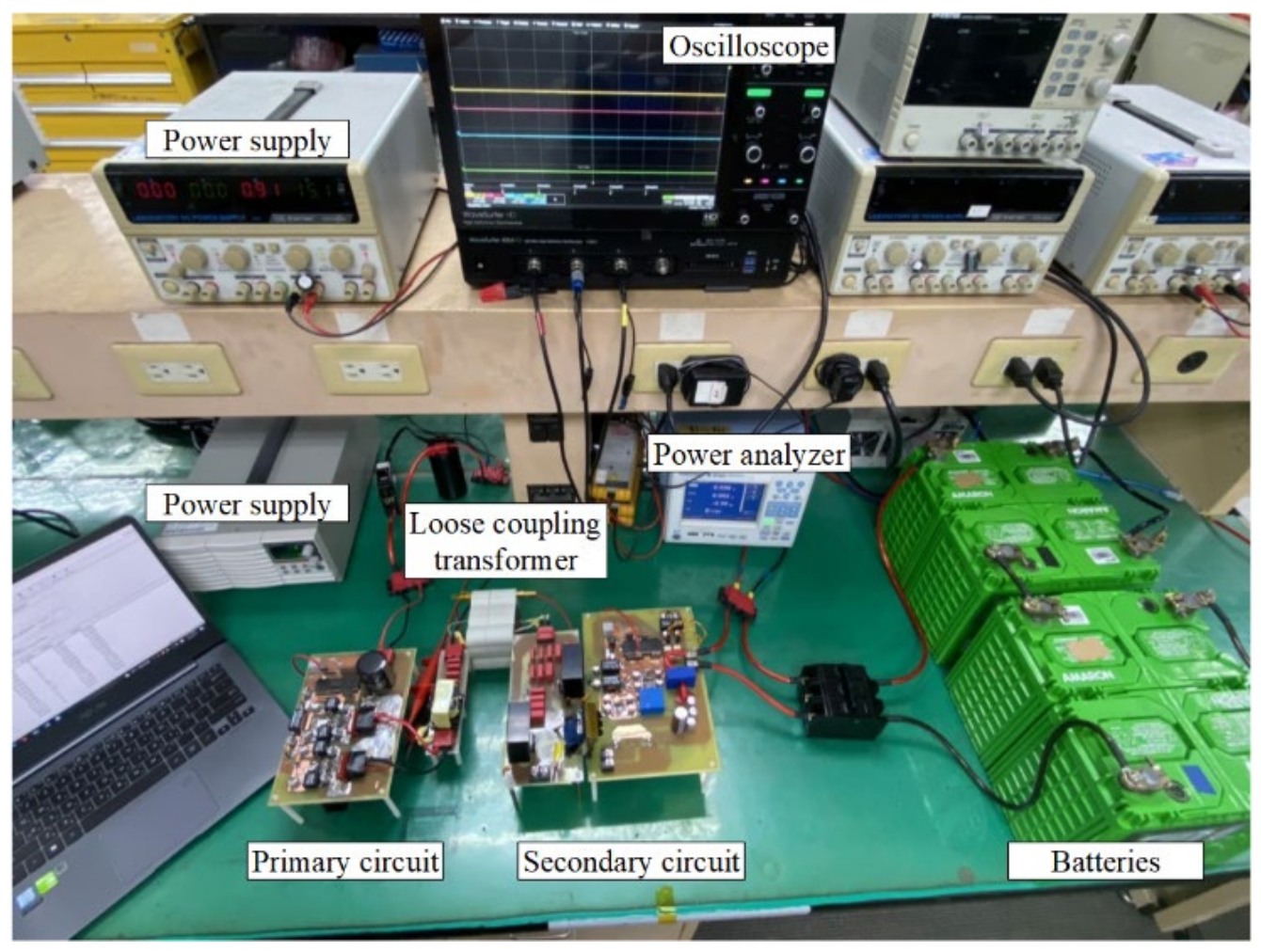
A 600 W hardware prototype of the proposed IPT battery charger with IR closed-loop control was built.
Figure 7 shows the photograph of the experimental setup including the primary side and secondary side of IPT topology, IR, and LCT coil. The size of the LCT coil including the shells was 58 mm × 58 mm × 25mm. The transmitter and receiver of the IR transmission interface were installed in the bobbins’ holes on both sides. The parameters of the constructed hardware followed the design of the simulation in
Table 2. The components of the semi-conductor as well as other chips are shown in
Table 3. In the following experiments, the charging current command was set as 10 A in CC mode, and the charging voltage command was 57.8 V in CV mode, which is suitable for charging an electric golf cart. The corresponding phase-shifted angle in CC and CV modes can be calculated from the charging voltage and current at MCU #2.
Figure 8 shows the IR communication signals on the receiver and transmitter. The data transmission was composed of a leader code and an 8-bit data code. The delay time between Rx on the primary side and Tx on the secondary side was nearly 0.3 ms. The duration of the leader, data, and stop codes were 3.4 ms, 6.6 ms, and 1.2 ms, respectively. The total transmission time was about 11.2 ms.
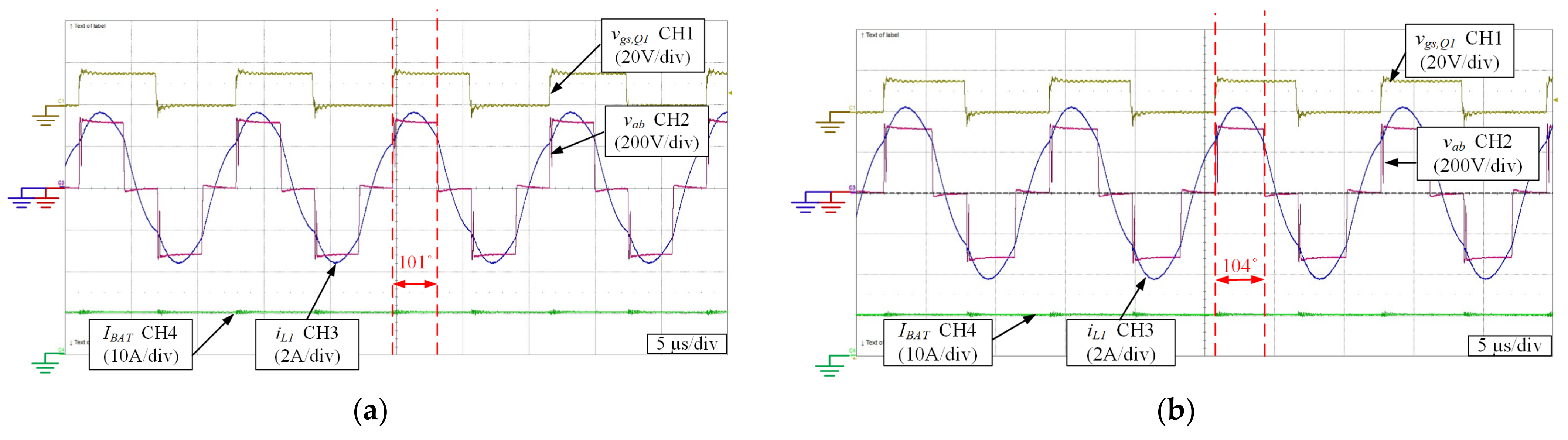
The waveform of the IPT configuration operated under CC mode is shown in
Figure 9, and the electronic load was operated in constant power mode as a circuit load to simplify the experiment operation. In
Figure 9a, the output power was about 480 W. To verify the performance of IR feedback under CC mode,
Figure 9b shows the waveform when the electronic load was operated at a constant power of 600 W. The current remained at 10 A in CC mode, and the phase-shifted angle was adjusted from 101° to 104°.
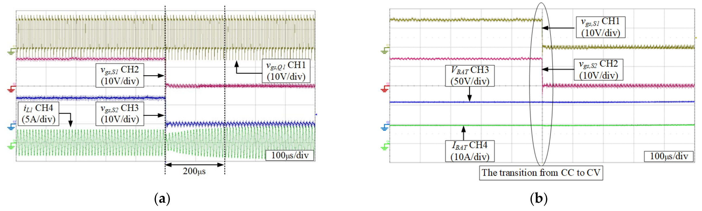
Figure 10 shows the transient waveforms of the IPT charger when the CC mode was switched to the CV mode. The gate drive signals
vgs,s1 and
vgs,s2 on the secondary side were switched at the same time to change charging mode from CC to CV mode. Due to the change in the configuration via switching
S1 and
S2, the phase-shifted angle should be pre-adjusted to accelerate the transition into a steady state. In
Figure 10a, the current
iL1 can be achieved to a steady state in only about 200 μs during the transition period.
Figure 10b shows that both
VBAT and
IBAT can achieve a smooth transition. In
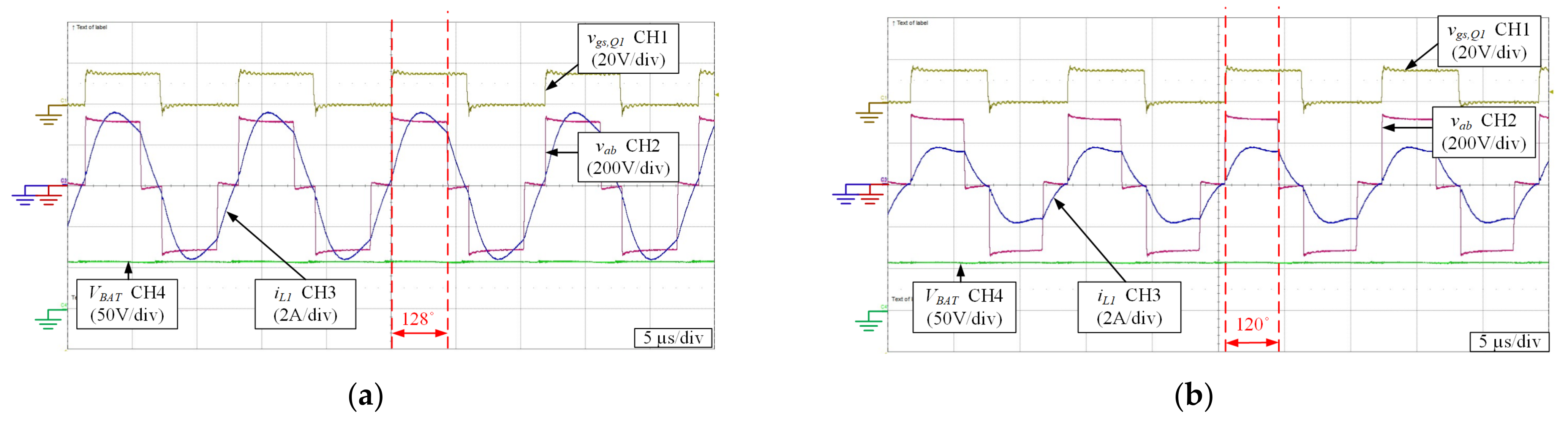
Figure 11, the IPT circuit was operated under CV mode, and the charging current was gradually decreased due to the remaining CV output. During the initiation of the CV operation, the peak value of the current
iL1 was 3.8 A while the phase-shifted angle was about 128°. As the battery was gradually charged, the phase-shifted angle was reduced to 120°, which was calculated from MCU #2 according to the charging voltage and current. The peak value of the current
iL1 was also reduced to 1.8 A at the same time. The voltage of the battery was maintained at 57.8 V, which shows that the voltage regulation function in CV mode.
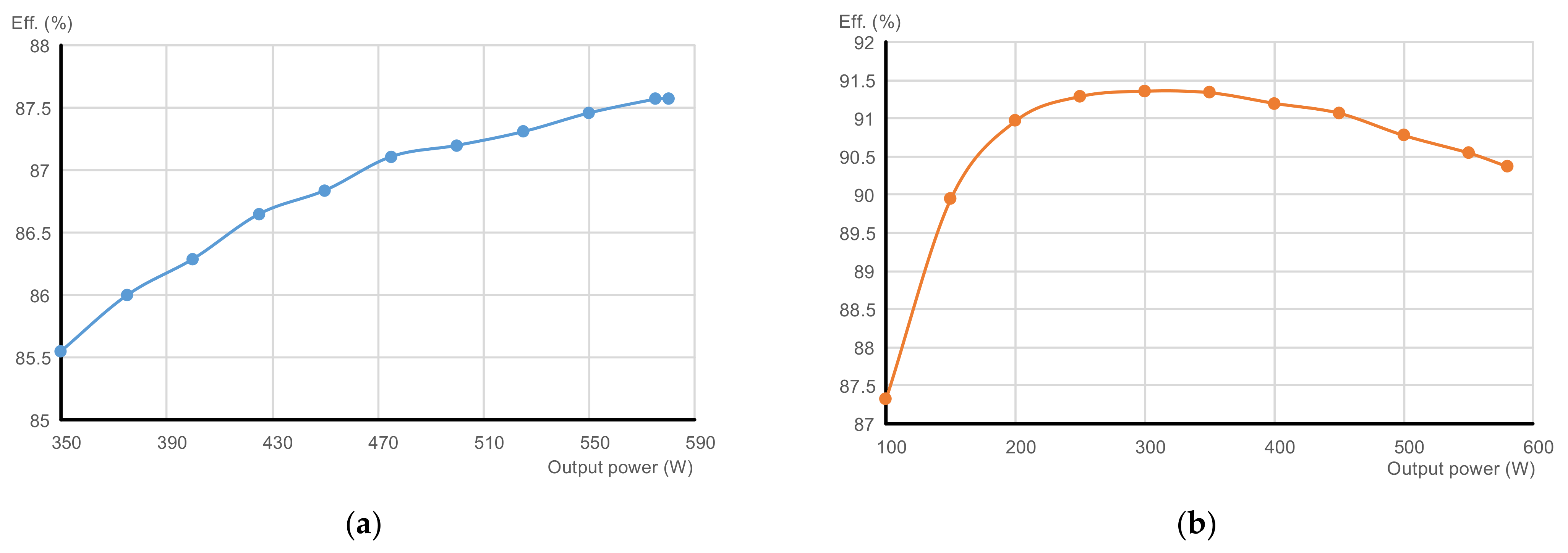
In
Figure 12, the efficiency was measured on the various output power with a different operation mode. It can be seen that the efficiency operating on CV mode had better performance than CC mode at the same power output. Although the number of resonant elements on the secondary side seemed to be the same in the two output modes, the conduction group of the bidirectional switch also needs to be considered in the case of constant current output. Hence, the loss in CC mode was higher than the CV mode. Furthermore, according to Equations (9) and (14), a larger phase angle to achieve the same output power is required at CC output. At the condition of the 580 W output power, the corresponding phase angle operating in CC mode was about 104° and the efficiency was 87.6%, while the corresponding phase angle operating in CV mode was about 128° and the efficiency was 90.4%.
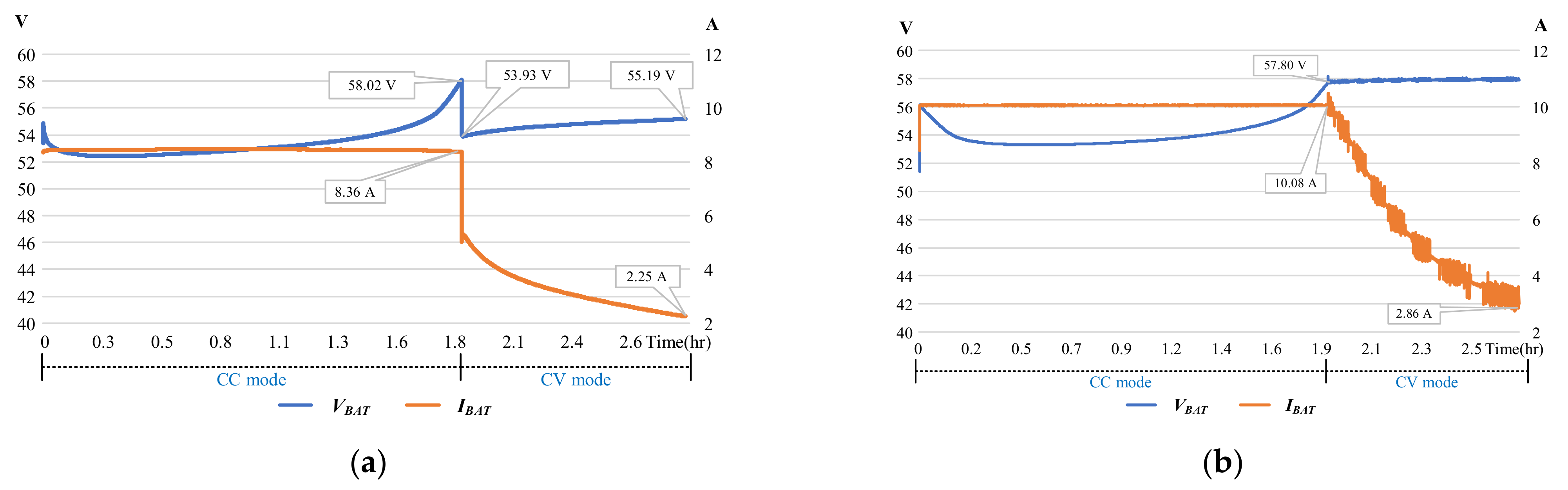
To investigate the difference between the IPT charger with and without closed-loop control, both experiments on the battery charging process were carried out and recorded. An open-loop-based result is shown in
Figure 13a, where the charging voltage and current drop immediately caused by the change in the circuit configuration when the mode was converted from CC to CV mode. During the CV mode, the voltage instantly dropped to 53.93 V caused by the mode transition, and then slowly rose to 55.19 V due to the continuous charging of the battery. The difference in the voltage drift between the beginning and the end of the CV mode was about 1.3 V, which cannot meet the requirement of CV charging. In
Figure 13b, the charging voltage of the closed-loop-based design can remain at a constant value of 57.8 V during the transient time from CC mode to CV mode. Compared with the open-loop-based design, the charging current can be maintained at a constant in CC mode and the charging voltage can be kept constantly in CV mode. On the other hand, the smooth conversion from CC mode to CV mode is unable to be achieved under open-loop control.


