Review

Roof Fall Hazard Monitoring and Evaluation—State-of-the-Art Review

1
Research and Development Center, KGHM Cuprum Ltd., 2-8 Sikorskiego Street, 53-659 Wrocław, Poland
2
Chair of Mining Engineering and Mineral Economics, Montanuniversitaet Leoben, Franz Josef-Strasse 18, 8700 Leoben, Austria
*
Author to whom correspondence should be addressed.
Energies 2022, 15(21), 8312; https://doi.org/10.3390/en15218312
Submission received: 6 October 2022 / Revised: 2 November 2022 / Accepted: 3 November 2022 / Published: 7 November 2022
(This article belongs to the Topic Advanced Systems Engineering: Theory and Applications)

Abstract

:
A roof fall hazard is still one of the major threats in the underground mining industry. Each such type of event always brings great risk to miners and causes serious interruptions in the process of rock excavation. In general, the possibility of roof fall hazard occurrence is directly related to the local geology, the presence of horizontal stresses as well as the type of excavation method and the efficacy of the utilized roof support. Due to the complexity of this process, it is important to continuously evaluate the roof fall risk, especially in long life-time places where a mining crew is often present. Within this article, a detailed review of the current methods of monitoring and evaluating roof fall risk was presented. Based on the extensive literature survey, different types of devices were described, and their advantages and disadvantages were pointed out. Furthermore, new trends in the area of roof fall risk monitoring were described and discussed.

1. Introduction

The underground excavation of deposits located at great depths in most cases is associated with roof fall hazard occurrence, which is one of the undesired and hazardous effects of the loss of stability of the mine workings. Generally speaking, these phenomena depend on uncontrolled and sudden roof failure, and the falling of rocks toward the excavated space, which constitutes a lethal threat to mining crews. This risk is widely observed and reported in the mining and tunnelling industry in Poland [1,2,3,4], the USA [5,6,7], Australia [8], China [9,10,11,12], South Africa [12,13,14], and India [15]. The level of risk directly depends on the local geological conditions, presence of tectonic disturbances and faults, type of operation, distance from mined-out areas, and type of applied rock support [1,7,8,9,10,11,12,13,14,15,16,17,18,19,20,21,22]. Additionally, environmental conditions such as temperature, water presence, and overall humidity may affect the probability of roof fall occurrence [23]. In most cases, the phenomenon of roof failure is an unwanted event that is harmful to the mining crew and equipment [24]. Still, there are some exceptional cases in which roof fall is an occurrence that is not only desirable, but also forced in a deliberate way, which, paradoxically, aims at increasing the safety of exploitation [25]. Such a situation may be observed in the example of underground mining performed with the use of room-and-pillar mining systems with roof deflection and room-and-pillar mining systems with forced roof fall. Both mining methods are utilized in Polish underground copper mines and their basic assumption is that the stresses generated by overlying rock mass reach a level that always leads to the destruction of the pillars. Therefore, to achieve a good excavation rate, the technological pillars that are excavated in the first stage are cut to smaller, post-critical dimensions that allow them to slowly yield under the rock mass pressure [26]. This solution also has a second important advantage, in the form of the minimization of risk of pillar burst, due to the lack of ability to accumulate energy by pillars of remnant size (Figure 1). In such an approach, the workings are liquidated solely by roof deflection, or if necessary by partly filling empty space with waste rock.
The exact dimensions of the pillars and workings were adjusted to the local mining and geological conditions. At the moment, in Polish copper mines, there are over 20 variants of room-and-pillar mining systems that are fit to the local strength of the rock, height of the deposit, presence of tectonic disturbances, and the presence of a mined-out area in the surrounding of the analyzed mining panel.
According to data presented in [6,24], the room-and-pillar mining system, aside from its advantages, seems to be prone to the occurrence of instability within the direct roof stratum, and therefore more effort has to be put into monitoring and evaluating such phenomenon in mines utilizing this system. Still, roof falls are also often in underground mine excavation with the use of a longwall mining system. As Prusek pointed out [1], roof falls are also common in underground hard coal mines where longwall and board-and-pillar mining systems are utilized.
To highlight the scale of the threat, roof fall-related accidents have to be mentioned. As presented in [12], only in the last 5 years, as many as eight tragic roof failures causing 86 deaths have occurred in China. A similar situation may be observed in coal mines in the U.S., where according to the report published by MSHA [27] in 2006, roof fall caused seven fatalities, 278 non-fatal days lost injuries, and 150 no-days-lost accidents. Worrying data in this regard were also recorded in Polish underground mining. According to the data presented by the Polish State Mining Authority (PSMA) in the years 1994–2013, most deaths in the Polish mining industry were caused by roof falls. For this reason, 93 people have died in the mines during the period of 20 years [28]. Unfortunately, this statistic has not improved in the last years, even with the utilization of more sophisticated evaluation methods and monitoring systems. As reported in the most recent document prepared by PSMA [29], the total accident rate observed in Polish underground copper mines in the last few years related to roof falls varies between 168 and 204 per year (Figure 2). Taking all of the above-mentioned into consideration, it may be stated that the development of new and more reliable monitoring systems and risk evaluation methods is one of the key goals that have to be achieved in the mining industry to ensure the safety, continuity, and efficiency of underground operations. Reducing the risk of developing hazardous situations should always be the primary goal, especially when it comes to ensuring safety in a confined workspace like a mine, where quick escape options are usually limited. As a result, risk management methodologies have been developed and successfully applied in underground mining. The complexity of interactions between people, machinery, explosives, and the rock mass, in addition to the numerous unknowns and incomplete knowledge of the rock mass, contributes to the need for risk assessment and management.
Within this paper, the current state-of-the-art (SoTA) in the scope of roof fall hazard monitoring and evaluation is presented. The methods and devices as well as the advantages and disadvantages of each solution are described based on the authors’ experience and an extended literature review. Additionally, new perspectives and ways of further development are analyzed and described. The goal of this review is to make mining operators familiar with the technology that is currently used worldwide and may contribute to increasing the efficacy of geomechanical hazard prevention.

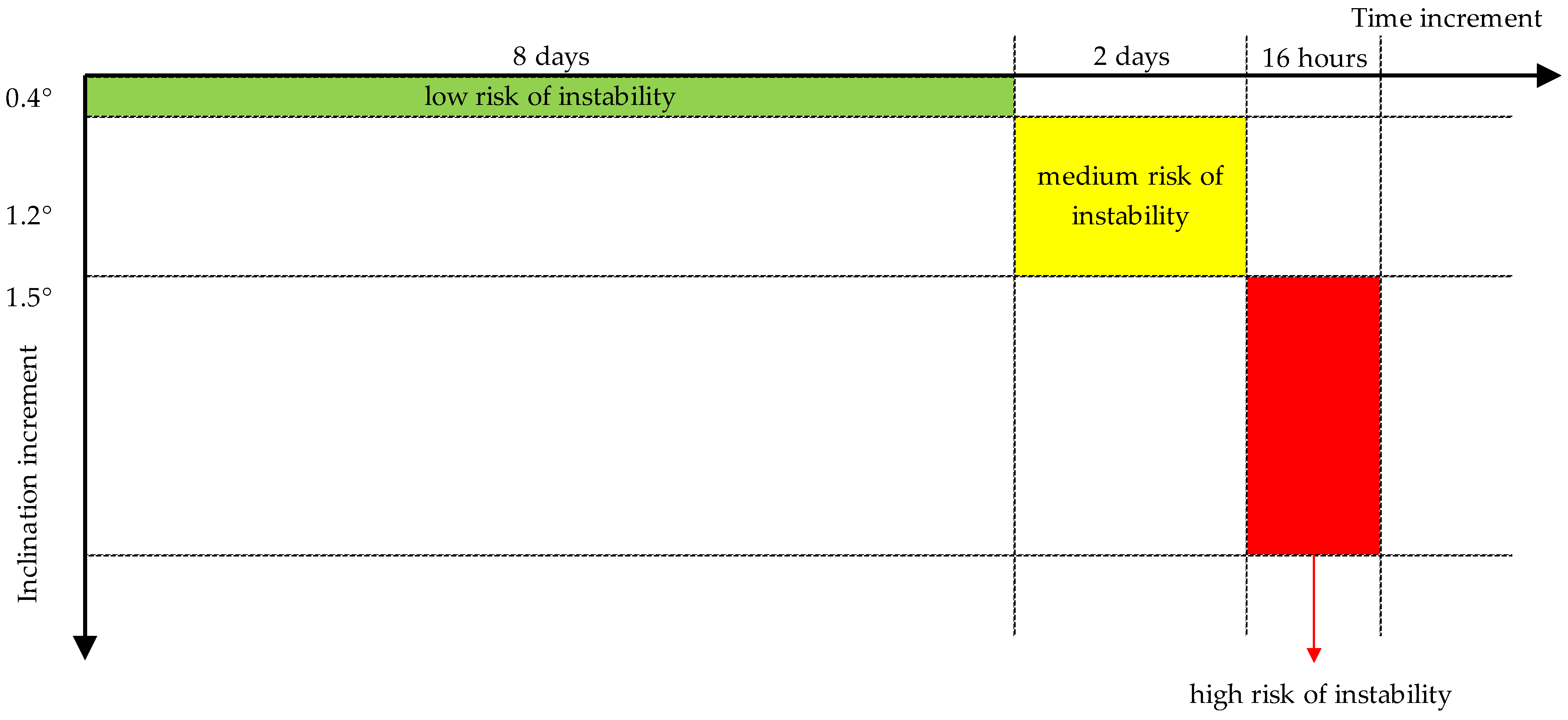
2. Indicators of Roof Fall Risk Development

Based on past research and experiences, it may be stated that roof fall is preceded by a number of indicators related to the disintegration of roof strata structure, changes in working geometry, and microseismic activity [30].
Every roof fall risk evaluation method requires the determination of the factors that contribute to the possibility of instability occurrence. As Ghasemi [31] pointed out, at the moment, several variables affecting roof fall risk are recognized and monitored. These variables include geology, depth of deposit, geometry of workings, horizontal and vertical stress levels, and type of support. According to the data presented in research works [13,32], the key factor affecting the risk of instability occurrence is the improperly chosen type of roof support. Furthermore, any defect in the roof support causing its poor performance is indicated (Figure 3).
Taking into consideration the high complexity of geomechanical failure, there is a great necessity for the development of novel monitoring and evaluation methods that will focus on multi-parametric analysis. First, the reliability of monitoring devices should be increased by an improvement in terms of the data resolution and implementation of continuous monitoring and data acquisition. After that, as Małkowski and Juszyński pointed out in [24], it is important to implement the complex and sophisticated methods of multiparametric hazard evaluation. This goal may potentially be achieved by the utilization of real-time based statistical analyses or the development of the so-called Internet of Things (IoT), which will hopefully allow mine operators to provide far-reaching awareness about the current rock mass state with respect to the presence of people, machines, and external negative impacts such as mining-induced seismicity. In general, IoT is the implementation of Internet connectivity into existing monitoring devices and sensors. What is crucial is the fact that after connection, different devices may be linked and interact with others, and data gathered simultaneously from all sensors can be remotely analyzed. In the case of the mining industry, IoT is currently in the testing phase, but it may potentially be used as a tool that is useful for lowering costs and optimizing the extraction process. It also may be useful in terms of health and safety improvement and analyze the probability of natural hazard occurrence.

3. Monitoring Systems—Current SoTA

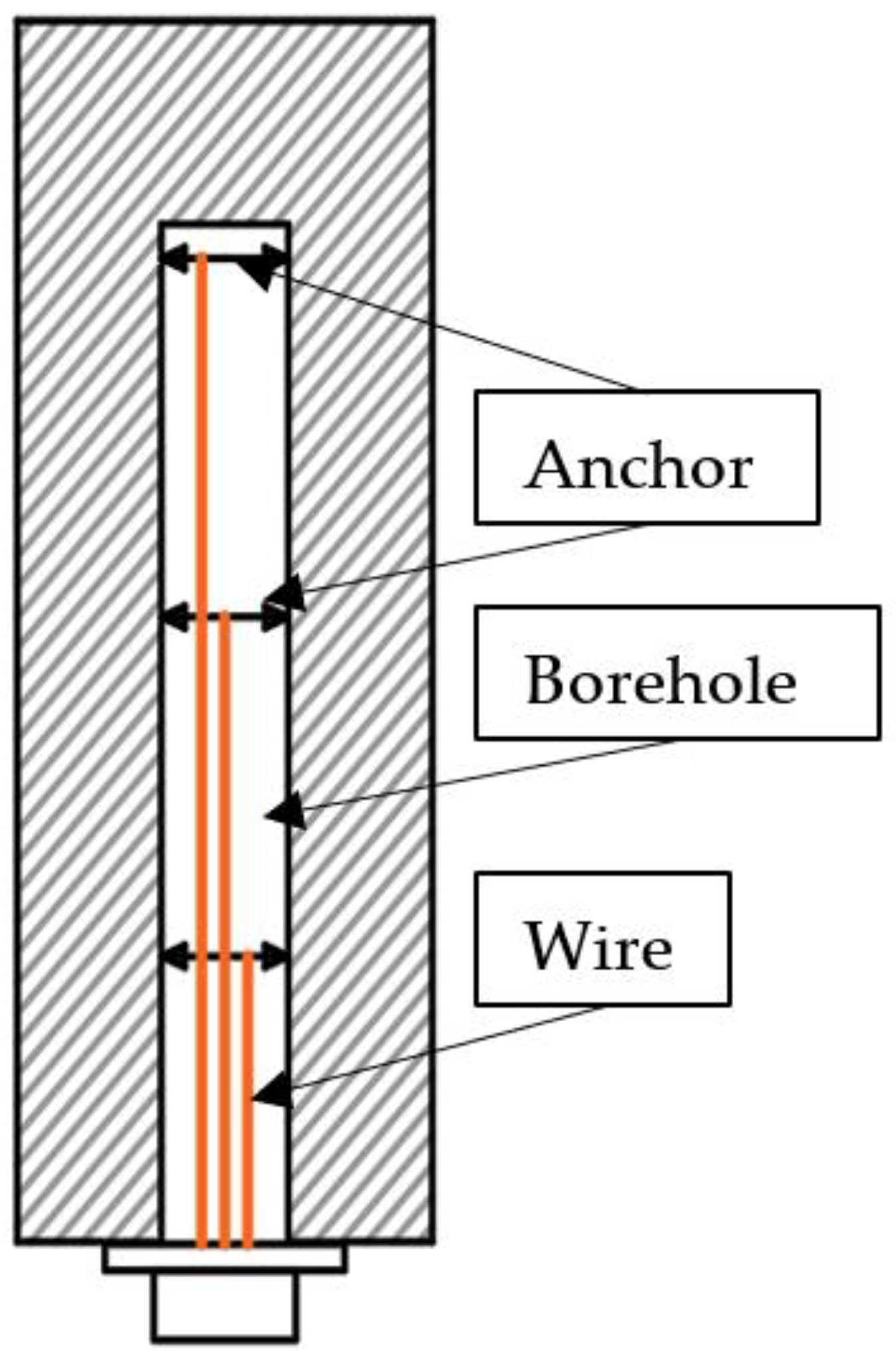
3.1. Borehole Monitoring

Control of the state of the rock mass and ground support condition by employing borehole cameras is one of the monitoring systems that are often used in underground mines [34,35,36,37]. Visual inspection produces valuable information regarding the rock mass quality in the roof layers described by parameters associated with the presence and character of discontinues such as cracks, joints, their directions, and distributions. The appropriate assessment of the rock mass in relation to the fracture structure, space distribution, and their alteration in time has an important impact on the selection and maintenance of the applied ground support [35,37,38]. It should be noted that by means of a borehole camera, apart from the simple visual inspection of roof layers, some of the rock mass quality parameters such as tunnel quality index (Q), the rock quality designation index (RQD), and rock mass rating index (RMR), etc. can also be evaluated [37,38]. The main elements of the borehole system can be seen in Figure 4.
It can be stated that a borehole monitoring camera is a relatively low-cost device compared to other measurement systems. Unfortunately, this system also has some drawbacks. In most cases, it is manually operated, and in some conditions, this kind of equipment tends to get stuck in drill holes and can be lost; it is also time-consuming, therefore, can only be used locally. Additionally, it should be mentioned that a reliable assessment of the rock mass current state and potential behavior should be extended to the other monitoring methods [34,36,38,39]. For instance, this type of monitoring can be easily expanded with simple displacement indicators for roof strata-like telltales in which strings can stabilize at two or more levels. This indicator allows for the assessment of displacements into roof strata in time. A combination of these two simple systems can measure displacement, if it occurs, and determine what happens in the roof (e.g., the delamination process) [35]. Nevertheless, visual inspection brings direct and valuable information about the state of the rock mass in the immediate vicinity of the working.

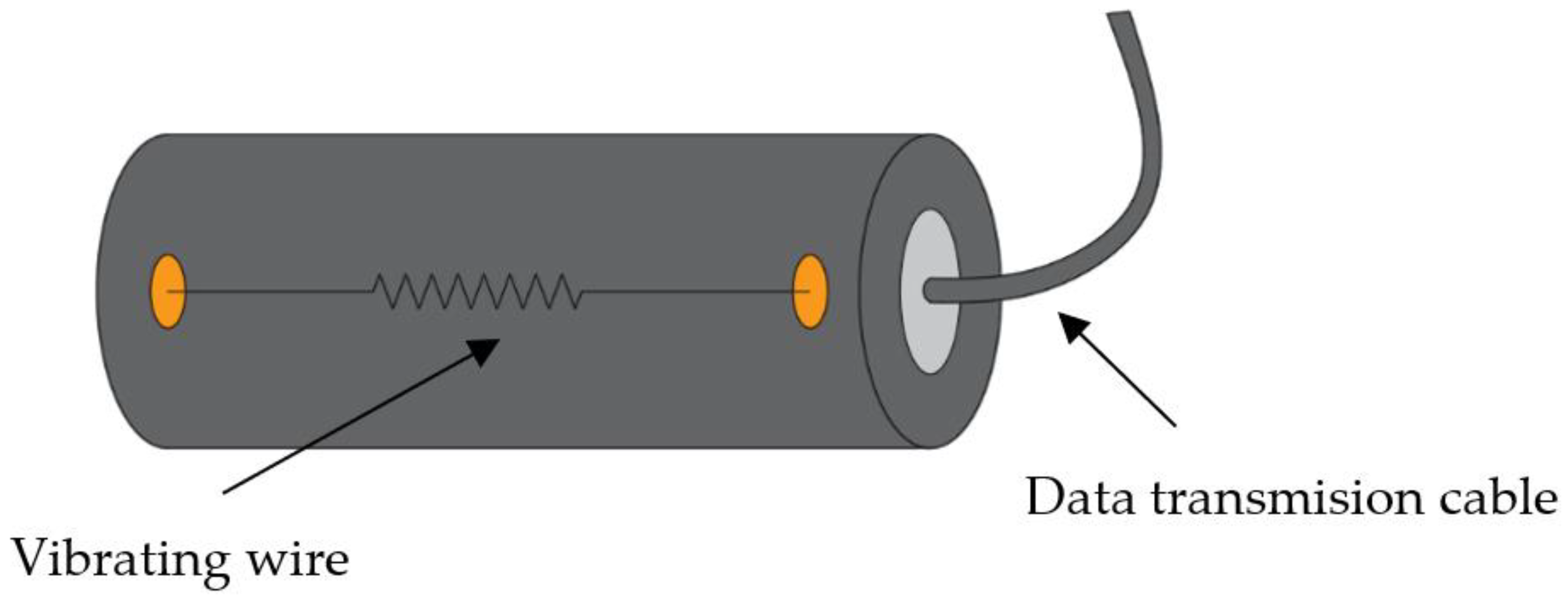
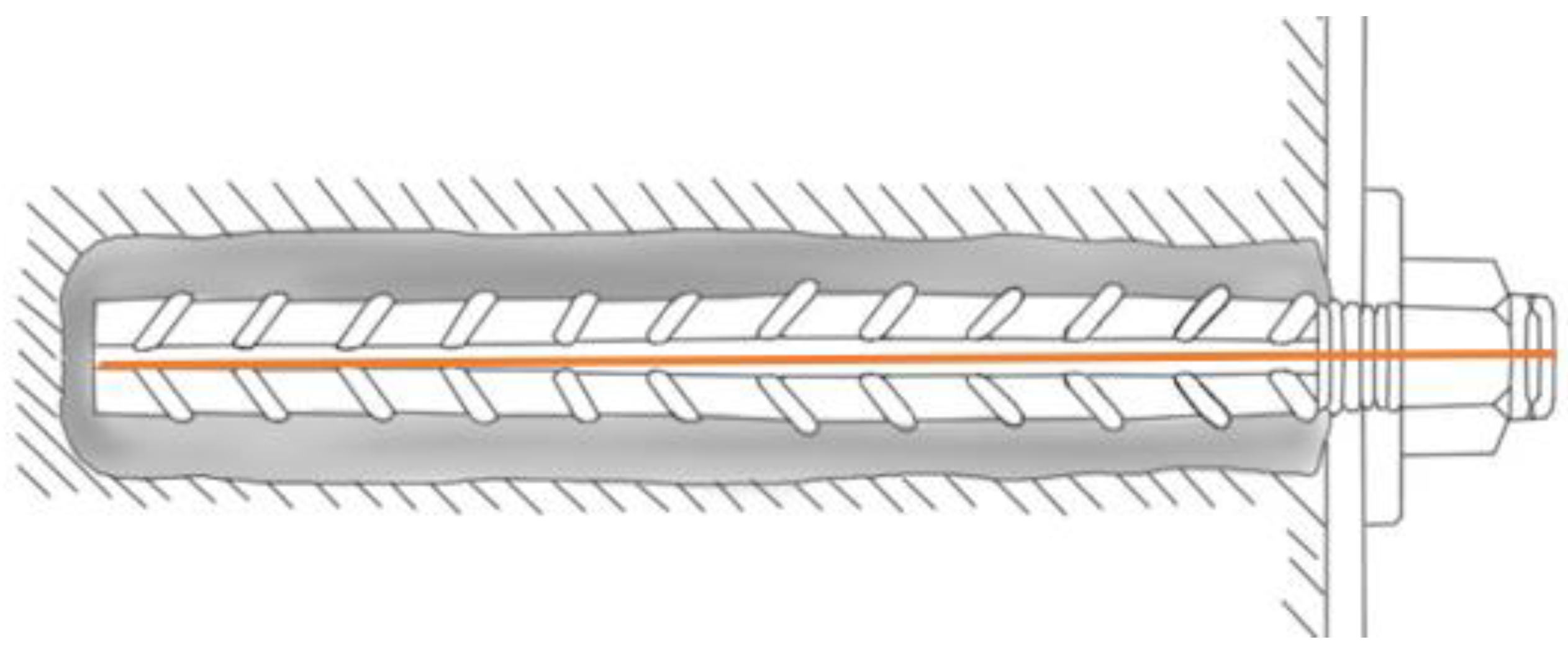
3.2. Instrumented Rock Bolt

Rock stress is an inherent part of the underground environment. Generally, in the intact rock mass, there is a state of balance that ensures the stability of the rock structure. Underground exploitation changes this natural and stable state, which can lead to the overload of some areas and the failure of underground man-made structures (e.g., in the form of rock falls). Therefore, in many cases, there is a need to support rock structures to maintain their stability. One of the most widely employed type of ground support to reinforce underground structures to ensure their stability is rock bolt. For a better understanding of the huge scale of using rock bolt in the worldwide mining industry, yearly usage of this kind of support exceeds 500 million [40]. Looking into this number, it is natural that rock bolt, equipped with special sensors, are often used to monitor stress in the immediate vicinity of the working, notably the roof strata. Data gathered from this kind of rock monitoring system are very meaningful to ensure workplace safety [39,40,41,42].
Depending on the type of sensor, there are different types of instrumented rock bolt. The following sensors can be used with rock bolt [43,44,45,46,47,48,49,50,51,52,53]:
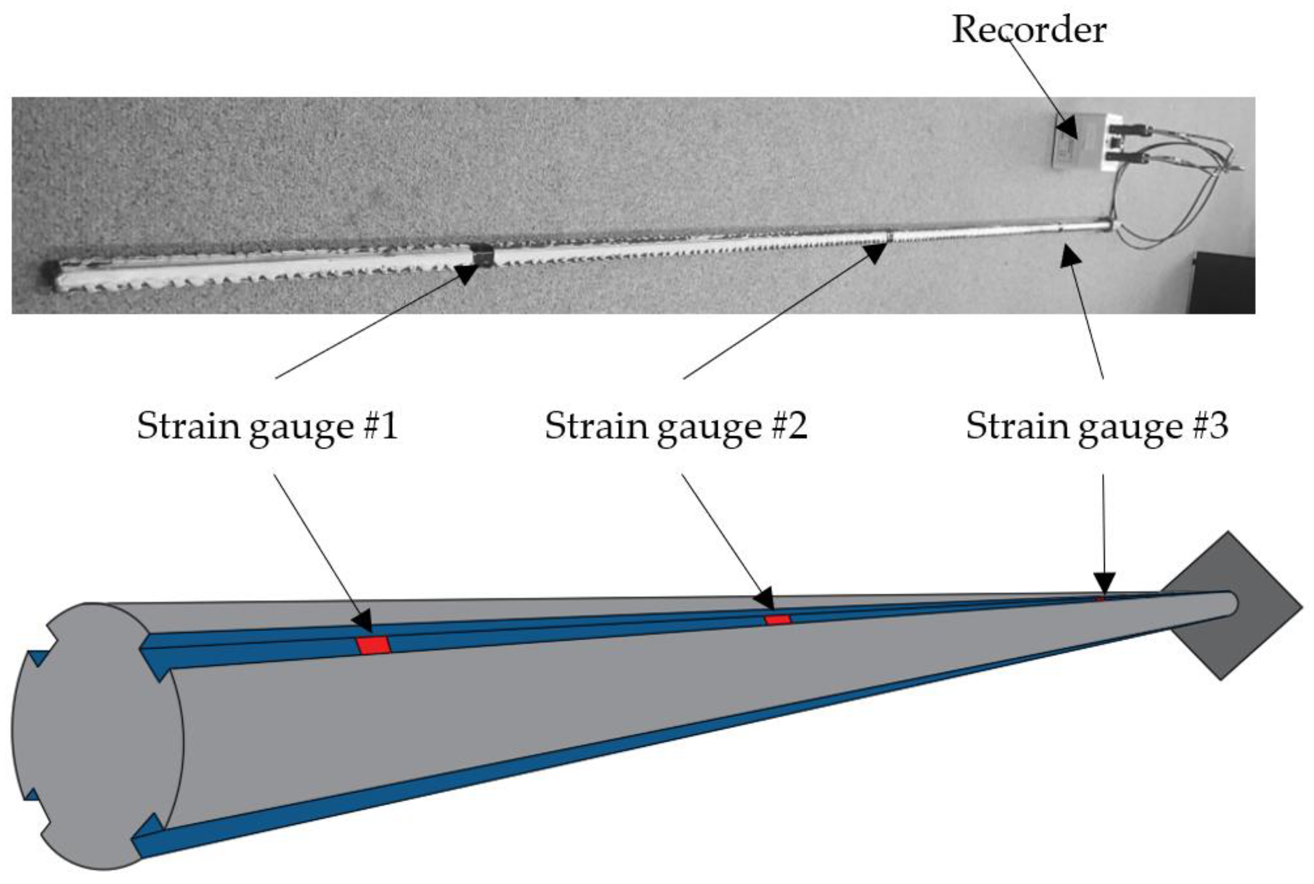
  • electric strain gauges;
  • vibrating wire;
  • optical fiber;
  • ultrasonic.
Instrumented rock bolt with strain gauges are based on an electric sensor that changes its parameters with bolt deformation. Strain gauges are installed along the rock bolt’s rod in different configurations depending on the length of the rock bolt and the assumptions that are made. An exemplary solution, with three measurement levels and four points on each level attached in four positions 90° apart, is shown in Figure 5. In Polish underground copper mines, there is also a more cost-effective version of this rock bolt with three measuring levels.
Generally, based on the measurement axial stress, the bending moment, displacement and shear stress can be determined. The drawbacks of this kind of solution are limitations in the resolution along the bolt and long-term stability; additional short base-length strain gauges can cover a small part of the rock bolt length. To avoid this shortcoming, long-base gauges can be applied [40,44,51,52]. With the use of a strain gauge-based instrumented rock bolt, the local roof fall risk may be determined easily by a comparison of the rock bolt’s rod strength and axial tension force generated by the rock mass pressure. Such an approach was tested in Polish copper mines, and the results indicated that rapid roof fall hazard increased a few days before failure (Figure 6).
Another type of sensor is based on the vibrating wire. In this method, the stress level is linked to the natural vibration frequency on the wire, which changes in relation to the tension value. This type of sensor is long-term stable, reliable, and is characterized by high accuracy. However, the vibrating wire gauge is fragile and can be damaged even before reaching its capacity limit. This kind of device can only measure the axial stress [40,47,48,53]. An exemplary concept of measurement by means of vibrating wire is shown in Figure 7.
In the last few years, strong attention has been paid to an instrumented rock bolt equipped with optical fiber sensors. This kind of sensor measures the parameters of the light that travels through the optical fiber. There are many different types of devices that employ different light technologies (i.e., fiber Bragg grating (FBG), and distributed optical strain-sensing (DOS)). There are many components that are crucial for correct working of the system based on the optical sensors, consisting, in general, of the following elements: source of light, receiver, modulator, processing unit, and optical fiber. This method can measure the axial loading, share loading, and bending moment [40,44,47,54,55,56,57]. There are some important advantages of fiber optical sensors (e.g., real-time, reliable, distributed measurement, high sensitivity, and corrosion resistance). It is worth mentioning that this technology can also be used with cable bolts. However, it should be stated that sensors based on optical fibers have limited strain measurement and are fragile, therefore, they should be properly protected from damage [40,55,56]. Depending on the sensor type, the length of the measuring line may exceed 1000 m and the spatial resolution reaches millimeters [55,56]
Apart from the technologies mentioned previously, another type of sensor should be presented, namely instrumented rock bolt with ultrasound sensors, which can measure load changes and deformation. Rock bolt are the path for ultrasonic wave transition itself, hence the meaningful advantage of this kind of technology is that there is no need to install any elements along the rock bolt, and the sensors are assembled at the exposed end of the bolt, therefore, they are relatively cost-effective. There is also potential for a large-scale monitoring system with clusters of rock bolt [40,43].

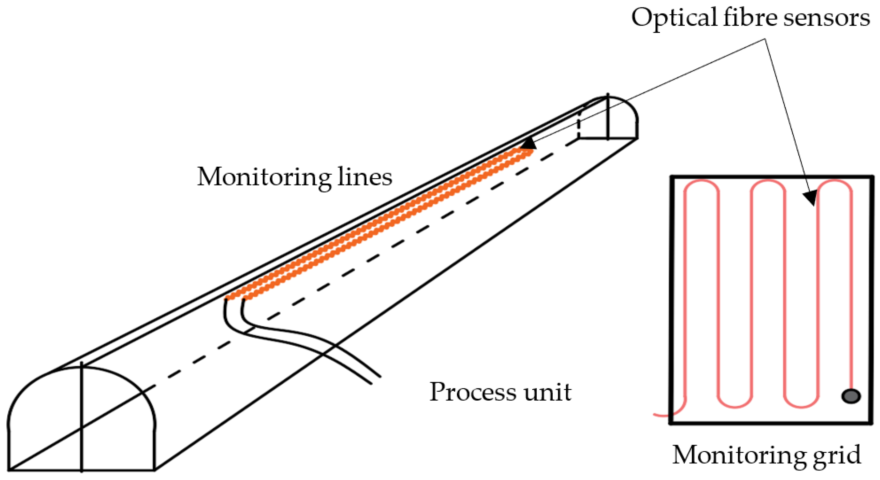
3.3. Optical Fiber-Based Monitoring Systems

Systems that use optical fiber sensors can also be employed to monitor geotechnical parameters not only by means of instrumented rock bolt. A proper design system can also monitor rock deformation in underground structures (e.g., workings, roadways, chambers, etc.). Monitoring can be built on the base of separate lines of fibers or as a spatial grid (Figure 8). This kind of system can also be used to even monitor massive structures (e.g., tunnels, mine still pillars, chambers, etc.) [55,58,59,60].

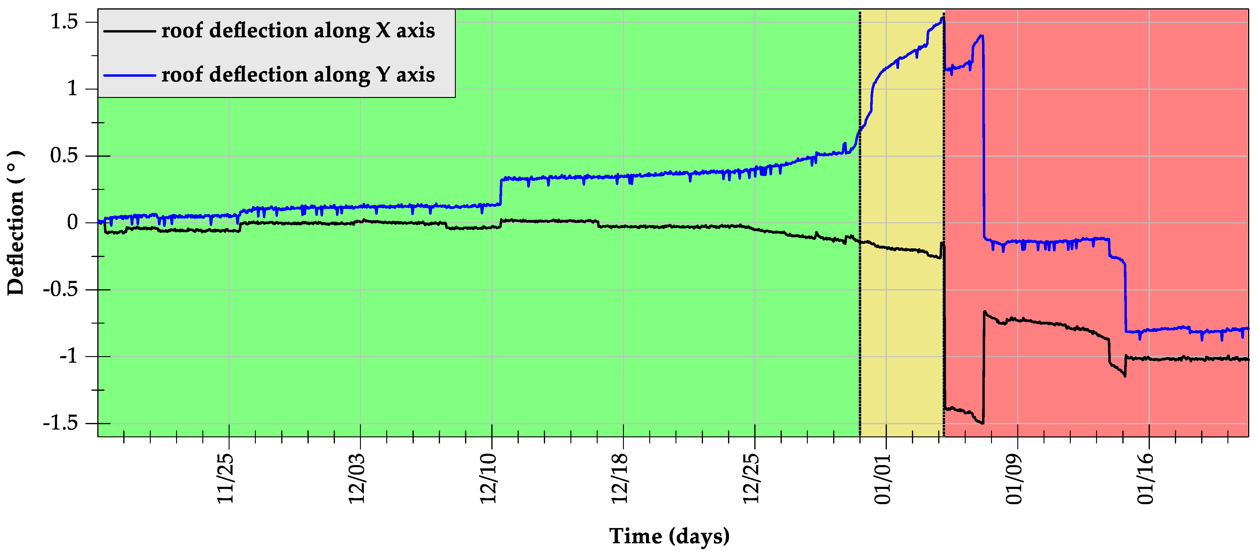
3.4. Roof Deflection and Delamination Measurements

Displacement monitoring of the roof strata is commonly performed by means of different types of extensometers [43,48,50,61,62,63,64]. In many cases, these are very simple and reliable devices that allow for monitoring of the roof. The working principle is very simple, namely, distance measurement is carried out between points where one of them is located and stabilized in the point in the roof, and is treated as stable over time, and the second one is moveable and is located at the collar of the borehole [47]. There can be more than one stabilized point, hence, the spatial resolution of measurement can be improved (multi-point extensometer) and therefore a more accurate location of roof delamination can be determined. There are also instruments available with automatic warning systems (e.g., auto warning tell-tale extensometer (AWTT)) [65]. A sketch of three-level mechanic extensometer can be seen in Figure 9.
Distance measurements can be performed by many methods (e.g., magnetic, electric, optic, mechanic, etc.) [61,62]. One example of an extensometer is a multilevel sonic probe extensometer (magnetic), which can monitor dozens of levels with an accuracy of <0.5 mm [61]. Deformation of the roof layers can also be monitored by inclinometers. Some of the laser devices are able to measure with a resolution of 0.02 mm/m [63].
In recent literature, there have also been attempts to analyze roof fall hazards with the use of roof deflection monitoring systems. According to the very detailed research described by Stolecki and Grzebyk [66], deflection of the roof occurs in the course of the destruction process of the roof strata. Therefore, a relevant long-term continuous monitoring of this process was executed by a newly developed inclinometric network. This network was built with the use of numerous autonomous sensors for the continuous tracking of roof deflection with a built-in module for wireless data transmission (Figure 10).
This system allows for the recording of changes in the spatial position of the inclinometer rigidly attached to the grouted rock bolt installed within the roof strata. Tests performed by the authors proved that the phenomena of roof collapses are strictly determined by the occurrences of the roof rock destruction preceding them. A similar conclusion may be drawn based on the result presented in [67,68].
Up until now, all preliminary test sites have been located in underground copper mines in the Lower Silesian Copper District in Poland. The collected database of roof deflection and the correlation of results with actual mining and the geological situation in the analyzed area allowed for the development of a so-called criterion to assess the stability of roof layers (Figure 11). This criterion illustrates the stages of roof destabilization as a function of time and the size of the slope angle change.
What is important is the fact that the criterion to assess the stability of the roof layers was tested in underground conditions and according to the preliminary analyses, allowing us to indicate the increase in roof strata failure occurrence a few days before the unwanted event (Figure 12).

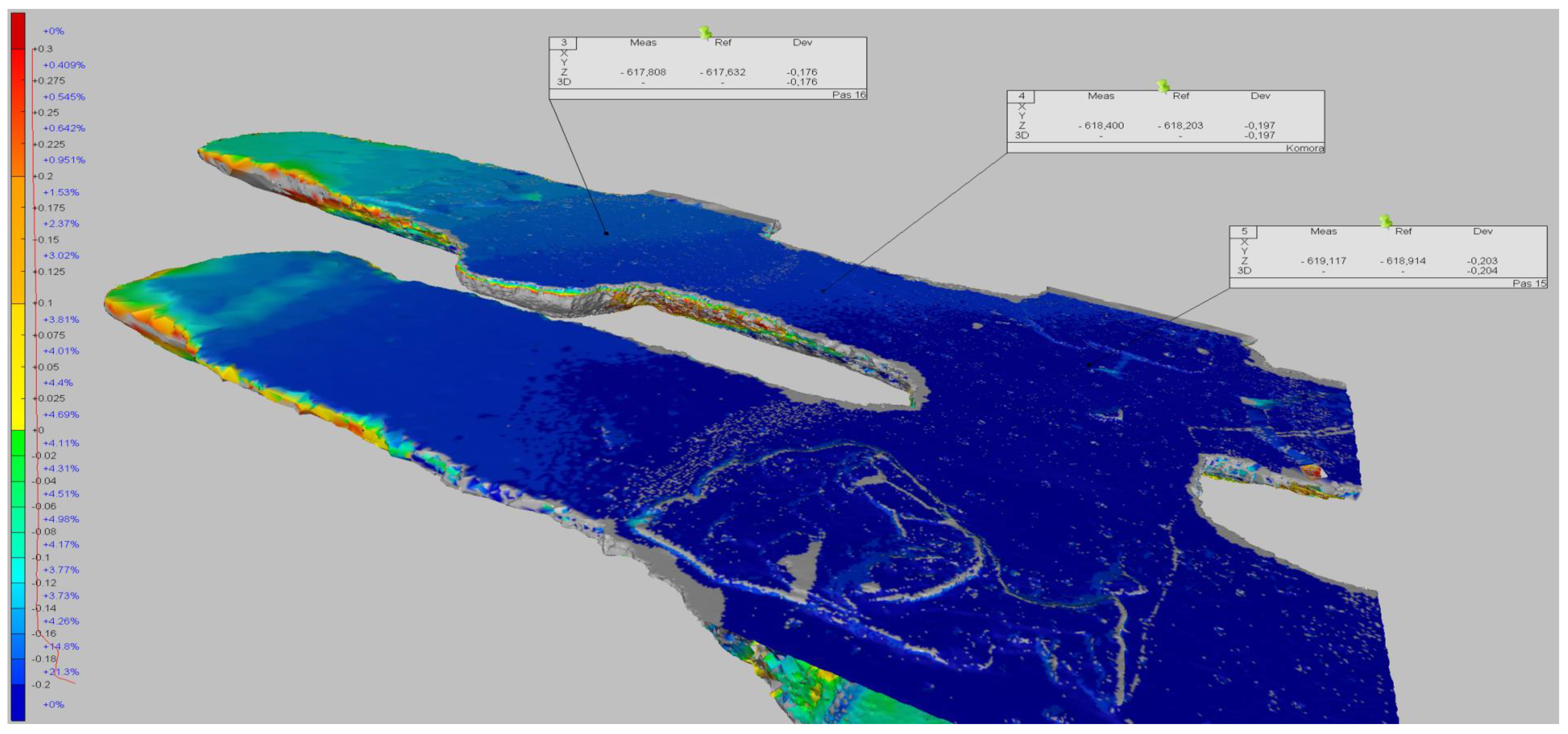
3.5. Geometry of Underground Workings

Apart from the above-mentioned monitoring methods of underground structures, there are other ones that are used more and more frequently, namely geometrical mapping. This can be achieved by means of radar, laser, or photogrammetric-based systems [69,70,71,72,73,74,75], the deformation of workings, tunnels, chambers, etc. to yield meaningful data regarding the behavior of the rock mass in time. These data can also be used to both build more accurate 3D models and to verify the results of the numerical modeling of rock mass [71]. A laser scan, which produces a cloud of points that represents the surface of the rock, can also be the source of data regarding the occurrence of discontinues and their parameters such as size, orientation, and density [75].
It should be stated that scanning systems provide millimeter accuracy with centimeter spatial resolution or even millimeters in the case of laser scanners [69,70,75]. In the case of radar systems, it even has sub-millimeter precision and a resolution of tens of centimeters, with the measurement in a real-time manner with data updated two times per minute [69]. Despite the advantages, there are still some important limitations of these technologies, for instance, even though current lasers are very fast (e.g., some scanners are able to scan hundreds of thousands of points per second), the scanning process can take a long time [70]. It must also be kept in mind that mining conditions can be very harsh and many of them can negatively affect the laser scanning process (e.g., poor light conditions, dust, humidity, water, mobile mining, etc.) [76]. Nevertheless, these monitoring methods are very promising and still under rapid development. It should be stated that radars and laser scanners are also used with drone technology, which allows the use of these methods remotely [70]. The exemplary 3D model of the underground workings’ deformation is presented in Figure 13.

4. Analytical and Numerical Risk Evaluation

In most cases, continuous monitoring with the use of the devices described in Section 3 allows the local risk of ground failure to be indicated. Due to the limitations of the recent technology, reliable stability monitoring of spatial underground workings is currently very challenging. However, some improvement in this matter has been recently observed due to the rapid development of numerical and statistical methods of ground hazard evaluation with the use of information about local geology, data from monitoring systems, and the description of historical cases of ground failure.

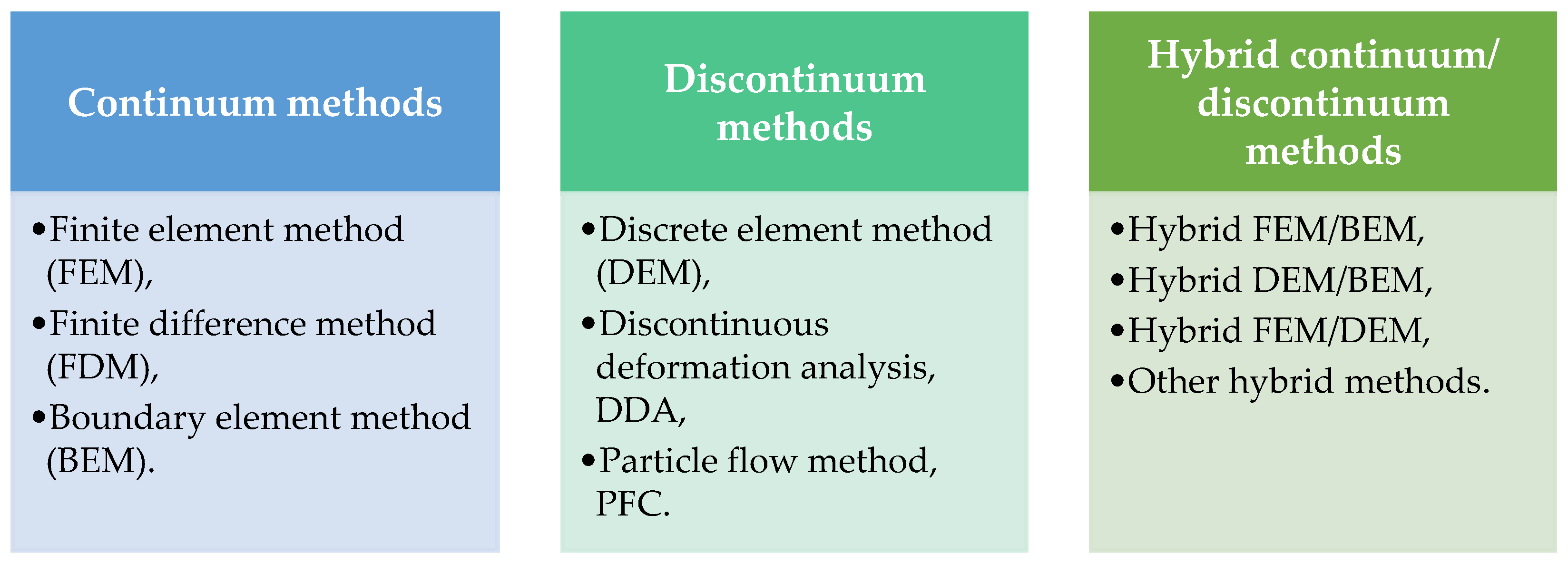
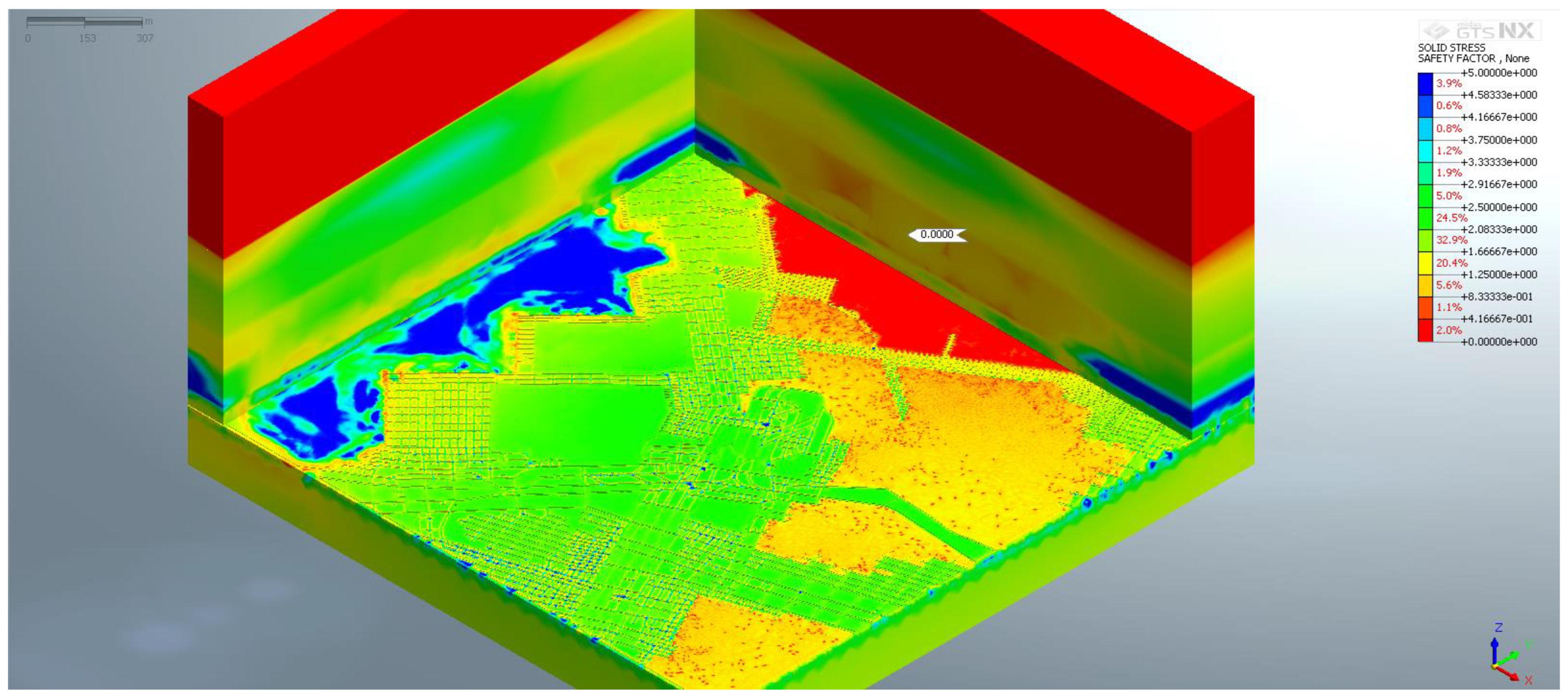
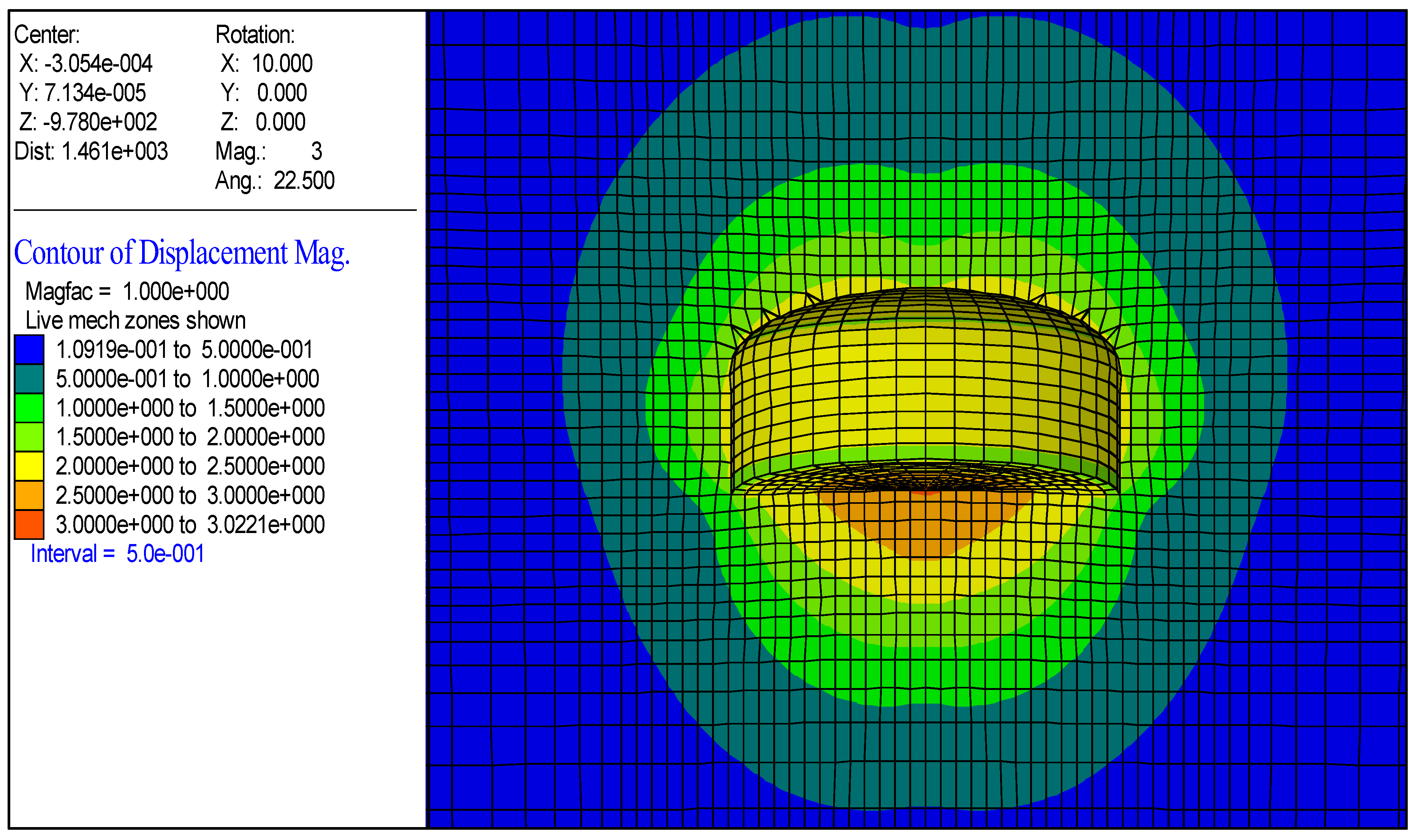
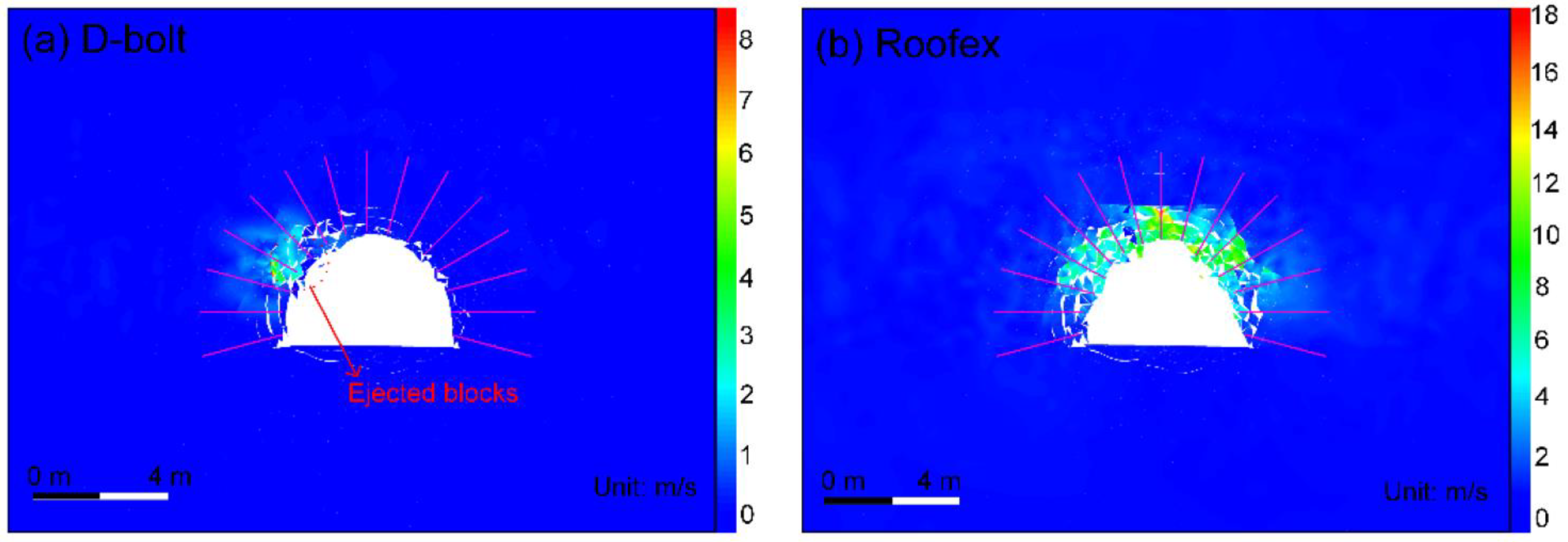
4.1. Numerical Modeling

The development of numerical methods in rock engineering has progressed very rapidly in recent years. Aside from the development of new computational methods, more reliable solutions allowing for a better description of the factual rock mass states are continuously being improved. The most common and currently applied numerical methods for underground excavation design, according to Barla [77], are presented in Figure 14.
The biggest advantage of numerical analyses is the possibility of determining the stress field and deformation in the surroundings of the mining excavation [78]. Due to the many years of the development of computational codes, it may be stated that the finite element method (FEM) is still the most commonly used. As pointed out by Pytel et al. [79], 3D FEM-based numerical modeling allows for roof stability to be determined in both the static and dynamic load condition. Still, the reliability of analysis strongly depends on the quality of the input data and has to be continuously validated with in situ monitoring results in the form of the stress and displacement distribution within the roof strata or the characteristics of seismic source and recorded waveforms in the case of dynamic analyses. What is important is the fact that due to the rapid development of hardware and the implementation of new more efficient codes into the most popular numerical software, it is possible to determine the roof stability in large underground areas, which is of the highest importance in the stage of planning underground excavation and periodical geomechanical risk evaluation in existing mining panels [79,80,81,82,83,84]. An exemplary distribution of safety factors within the immediate roof strata is presented in Figure 15.
There are also numerous analyses of underground working stability performed with the use of the FDM method [85,86,87]. An example of the underground chamber stability analysis with the use of FLAC 3D software is presented in Figure 16.
With the increase in the software and hardware capabilities in methods of underground structure, design has evolved rapidly and more notice is being paid to discontinuum models that theoretically allow for the evaluation of the stability of fractured and highly jointed rock mass subjected to static and dynamic load conditions. Discontinuum methods may be used in analyzing the complex process of rock mass fracture and the complex interaction between seismic waves, and the roof supports rock masses during different types of load [88]. An example of the use of the DEM method for the purpose of rock bolt support performance in the enforcement of fractured rock mass is presented in Figure 17.
According to [77], even more advanced numerical models may be prepared by combining different simulation methods. A good example of combining different methods was presented in [89,90], where a hybrid approach FDM/DEM with the use of combined FLAC and PFC developed by the Itasca Consulting Group, Inc., USA was used. Such an approach allows for the prediction of rock fracturing around underground excavations driven in the anisotropic rock mass, and finally determines its stability and effective support methods. The hybrid approach is also suitable for the determination of rock bolt patterns and spacing. The results are also important from the point of view of roof support loading capacity, which is the base information necessary to ensure the stability of the underground excavation.

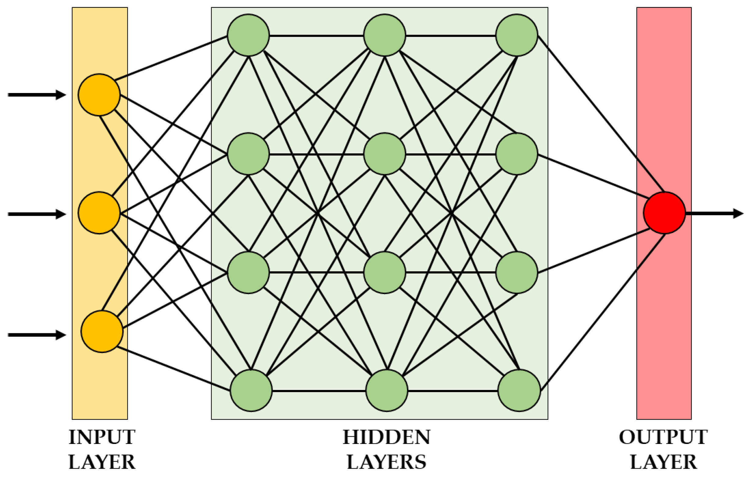
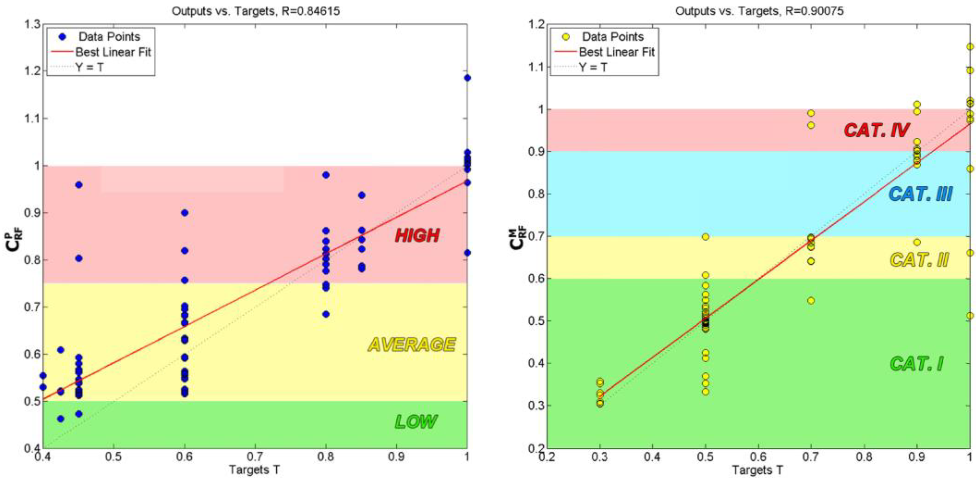
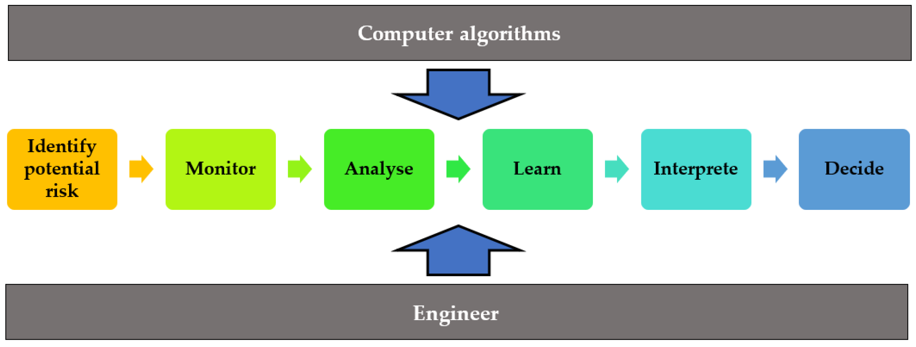
4.2. Machine Learning and Artificial Neural Networks

Artificial neural networks (ANNs) are mathematical tools that allow for the identification of complex relationships between variables in the form of correlation, patterns, and clusters that exist in a collected database [91]. A neuron accepts an n input data and processes the data to present a single output according to the scheme presented in Figure 18.
In recent years, roadway stability based on neural networks has developed very actively [92]. An example approach proposed by Mahdevari et al. [93], based on the development of an artificial neural network with the use of a multilayer perceptron network, allowed them to achieve a satisfactory level of fitting between the predicted values and observed roof displacement, reaching R2 = 0.9109. The study included a number of parameters describing the rock mass strength, which were used as an input of the model including uniaxial compressive strength, tensile strength, cohesion, angle of internal friction, Young’s modulus, shear strength, density, slake durability index, and rock mass rating. The output value was roof displacement measured with a dual height telltale. As was pointed out by Zhang et al. [92], the approach proposed in [93] seems to be one of the first reliable research aimed at the use of AI in the stability prediction of underground workings. Still, it was concluded that the quality of the output data strongly depends on the number and quality of the input factors. As Małkowski and Juszyński [24] pointed out, there are numerous recent examples of the use of an ANN in underground engineering in which the connection between the input and output data is not clearly defined. Some approaches were based on tracking rock mass fractures and the correlation of results with geological structure and the rock mass parameters [94,95,96]. There have also been numerous works concentrated strictly on the parameters of rock layers in the direct surrounding of the underground space [94,97,98,99,100].
A very detailed and sophisticated study was prepared in 2021 by Małkowski and Juszyński [24], who based on the AAN analysis developed and proposed the roof fall hazard index for underground copper mines located in the Legnica-Głogów Copper District, Poland. As a result of detailed analysis, four stages of rock mass propensity to failure were determined and the correlation between the output values of the roof fall hazard index and target reached the level of R = 0.85, which is very promising. Additionally, the evaluation of roof fall hazards was satisfactory due to the correlation between targets and the outputs at the level of R = 0.90 (Figure 19).

5. Innovative Solutions under Development

With the implementation of development actions according to Industry 4.0, the digital transformation of the mining industry may also be observed. It assumes inter alia integration of novel, more reliable technologies including the Internet of Things (IoT), cloud computing and analytics, big data analyses, and the implementation of machine learning and artificial intelligence (AI) into the excavation and underground working maintenance process (Figure 20).
However, this kind of comprehensive solution fit to the particular site are still under development. Some preliminary conclusions are presented below.

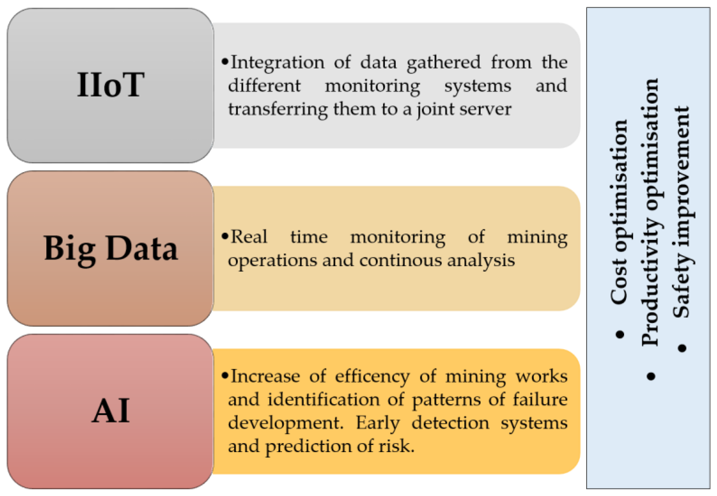
5.1. IoT in the Mining Industry

The implementation of IIoT in the mining industry will be the base of a more complex evaluation of the whole exploitation process. This is why there are numerous mining projects related to the development and testing of new digitized methods in underground sites worldwide. All of these activities are aimed at improving the extraction efficiency, increasing the safety of the mining crew and equipment, and transforming from preventive to predictive decisions. Some successful examples of the implementation of IIoT in mining are presented in Table 1.
Unfortunately, most of the successful cases of IIoT implementation in underground mining are related to machine monitoring and an increase in production efficiency. Things seem to be more complicated in the case of the prediction of a natural hazard, whose nature has not been fully recognized yet. Nevertheless, some actions have been already undertaken in this regard.
Based on an understanding of recent scientific and technological advancements, a general direction of further development may be set. One of the promising activities related to the improvement in roof fall monitoring and evaluation in underground conditions is being developed within the EU co-founded project with the acronym illuMINEation. Within the scope of this project, the innovative cost-effective roof stability monitoring system, supported by the Industrial Internet of Things (IIoT), was developed and tested in real underground conditions. As pointed out in [102], wherever there is a mechanical excavation taking place, rock mass instability poses a problem. The installation of rock bolt as well as the use of other support systems such as cable bolts, steel mesh, and shotcrete, can solve this problem. However, because rock mass is a complex natural material, it is challenging to generalize the solution. There are a number of methods for choosing the right type of support [103]. The behavior of rock mass can be predicted using geological data in conjunction with bolt deformation data and potential local or regional instabilities [104]. Joint orientation and positioning with the deformation value measured by rock bolt in the mine area revealed potential weak spots in the rock mass as input data for evaluating rock mass stability. In addition to value, bolt measurements can identify movement. Therefore, extended research on the development of a cost-effective roof fall monitoring system has been conducted. The low-cost sensors allow for significantly increased coverage of the mine area, and instead of a few monitoring posts, almost all rock bolts can be equipped with measuring devices at virtually no extra-costs compared to the standard bolt. What is important is the fact that all measurements are supported by machine learning methods and big data analysis systems, which allow for forecasting movements in the rock mass once sufficient data are available.
Bolts with a measuring system in place have the ability to show changes and signal sensor damage, if it is present. Therefore, it may be stated that intelligent rock bolts are simply regular bolts with extra equipment that aids in the detection of potential instabilities and damage within the rock mass as well as showing changes in deformation and other additional information, depending on the type of sensor device. With the help of further analysis and other variables that can be calculated from the data already collected, it will be possible for us to determine the state of the rock mass. The scheme of the newly developed rock bolt prototype to measure roof bolt deformation is presented in Figure 21.

5.2. Novel Cost-Effective Solutions

When analyzing the innovative solutions that are still under development, cost-effective devices should also be mentioned. The development of low-cost sensors with reliable accuracy may bring many advantages to the quality of the obtained data, mostly due to the increase in the coverage level. An increase in the network density may be the basis of drawing conclusions about the potential risk not only locally, but also on a global scale in particular mines. In the scope of ground control monitoring devices, micro-electro-mechanical systems (MEMS) seem to be one of the most promising ones due to their great accuracy in static and dynamic conditions, and robustness, which makes them suitable for use in a harsh underground environment. At the moment, MEMS-based devices are widely tested in mining seismology. As highlighted in [105], data about ground motion recorded with MEMS-based accelerometers may be effectively applied for systematic observation of near-field strong ground motion. In Figure 22, the comparison of PSD of the noise recorded by a mine seismometer and cost-effective MEMS accelerometer is presented.
There are also MEMS-based inclinometers that make it possible to significantly increase the quality and resolution of data regarding roof deflection in Polish underground copper mines.

6. Conclusions

The efficient prevention of roof fall hazards in underground mines requires the implementation of the continuous learning process, which has to be developed according to the main principles of measure, diagnosis, and treatment. Additionally, it is crucial to implement these risk management rules into safety systems used in underground conditions. This entails learning about the capabilities and limitations of the existing monitoring systems, their combined use, and how they can be installed and run efficiently. Moreover, one of the goals of the integrated learning process is to transfer the experience gained by engineers and miners over the course of their careers to an objective platform that can be contributed to and accessed by anyone. Thus, the IIoT platform plays an important role in constructing this experience by storing, reporting, and analyzing events. The IIot platform can be successfully implemented when every bolt is covered with a sensor, and it is only viable if the sensors are extremely low cost. This dense network of bolts would provide high-resolution data coverage. On this basis, new and improved algorithms for data analysis can be developed as well as a better understanding of the response behavior of the rock mass as a result of excavation activities (Figure 23). This concept must be robust and simple in order for it to be applied successfully in real life. It should cover the basic installation of the monitoring system, data transmission, data storage, data analysis, data visualization, protocol storage for events that occurred, set measures, and its back analysis.
Future development requires the integration of different types of monitoring systems and continuous real-time evaluation of the hazard based on the collected data. An increase in the reliability of measurement systems will undoubtedly turn into the development of new, more reliable risk evaluation and prediction methods. It will be also the basis for the development of a more detailed and accurate numerical model that may positively affect periodical geomechanical risk assessment and the planning of underground excavation in challenging geological conditions. Still, at the moment, all these actions are related to many challenges, mostly technical. For example, the rapid evolution of numerical modeling tools in rock engineering allows for the preparation of a very accurate representation of the real, in situ conditions and thus forms the basis for the prediction of rock mass behavior in different load conditions. Discontinuum and hybrid modeling seems to be the most promising and are gaining importance every year, but due to the lack of precise information about rock mass, the discontinuity characteristics may also lead to significant errors, jeopardizing the safety of mining excavation.
An IIoT-based approach, aside from the visible advantages, also has to be further developed. At the moment, one of the biggest obstacles is related to the technological limitations of mine infrastructure. In order to properly implement large-scale IIoT, mining operators have to provide a sufficient data transfer capacity for simultaneous data collection and transfer between devices. Another important challenge is the resolution of data from mine monitoring systems. Due to the high costs of installation and maintenance, monitoring networks such as seismological, ventilation, or piezometric network are limited to a reasonable minimum. The implementation of low-cost devices to regular use may bring tangible benefits in the form of an increase in mine coverage with monitoring devices without a visible increase in costs. Summarizing the rapid development of technology and the intensification of works related to the development of mining technologies year by year will undoubtedly be associated with an increase in the accuracy of the monitoring and prediction of geomechanically hazards in mines. The simultaneous application of multi-parametric data analysis, statistical methods, and new cost-effective devices, already at the testing stage, will bring many benefits in terms of recognizing the characteristics of the rock mass and preparing more accurate models of the destruction of the rock mass. Therefore, further work is needed in this area.

Author Contributions

Conceptualization, K.F., L.S., M.S. and W.P.; Methodology, K.F., L.S., M.S. and I.J.-P.; Software, K.F., L.S. and M.S.; Validation, K.F., L.S. and W.P.; Formal analysis, K.F., L.S. and I.J.-P.; Investigation, K.F., L.S., M.S. and I.J.-P.; Resources, K.F. and L.S.; Data curation, K.F. and L.S.; Writing—original draft preparation, K.F., L.S. and M.S.; Writing—review and editing, K.F., L.S., M.S, M.J., M.N. and P.H.; Visualization, K.F., L.S., M.S. and M.J.; Supervision, K.F., L.S., I.J-P. and W.P.; Project administration, K.F., L.S. and P.H.; Funding acquisition, K.F. and P.H. All authors have read and agreed to the published version of the manuscript.

Funding

This paper was prepared within the framework of the illuMINEation project. The project has received funding from the European Union’s Horizon 2020 research and innovation program under grant agreement No. 869379.

Data Availability Statement

Not applicable.

Conflicts of Interest

The authors declare no conflict of interest.

References

  1. Prusek, S.; Rajwa, S.; Wrana, A.; Krzemień, A. Assessment of Roof Fall Risk in Longwall Coal Mines. Int. J. Min. Reclam. Environ. 2017, 31, 558–574. [Google Scholar] [CrossRef] [Green Version]
  2. Martyka, J.; Hetmańczyk, P. Annual Report: The State of Natural and Technical Hazards in Polish Hard Coal Mines in 2013; Report under Prof. Kabiesz Lidership; GIG: Katowice, Poland, 2013; pp. 15–27. (In Polish) [Google Scholar]
  3. Biliński, A. The Symptoms of Rock Mass Pressure in Longwall Panels Located in Hard Coal Seams; Zeszyt Naukowy nr 221, Górnictwo z.31; Politechnika Śląska: Gliwice, Poland, 1968. (In Polish) [Google Scholar]
  4. Rajwa, S.; Płonka, M.; Lubosik, Z.; Walentek, A.; Masny, W. Principles of safe use of powered supports. In Proceedings of the School of Underground Mining, Ukraina, Jałta, 5–12 October 2008. [Google Scholar]
  5. Duzgun, H.S.B.; Einstein, H.H. Assessment and Management of Roof Fall Risks in Underground Coal Mines. Saf. Sci. 2004, 42, 23–41. [Google Scholar] [CrossRef]
  6. Gregory, M.; Christopher, M.; Debasis, D. Using the coal mine roof rating (CMRR) to assess roof stability in US coal mines, Mining industry annual review. J. Mines Met. Fuels 2001, 15, 314–321. [Google Scholar]
  7. Mark, C.; Pappas, D.M.; Barczak, T.M. Current trends in reducing groundfall accidents in US coal mines. Min. Eng. 2011, 63, 60–66. [Google Scholar]
  8. Evans, R.; Brereton, D.; Joy, J. Risk assessment as a tool to explore sustainable development issues; lessons from the Australian coal industry. Int. J. Risk Assess. Manag. 2007, 7, 607–619. [Google Scholar] [CrossRef]
  9. Wu, W.D.; Bai, J.B.; Feng, G.R.; Wang, X.Y. Investigation on the mechanism and control methods for roof collapse caused by cable bolt shear rupture. J. Eng. Fail. Anal. 2021, 130, 105724. [Google Scholar] [CrossRef]
  10. Lyu, H.M.; Sun, W.J.; Shen, S.L.; Zhou, A. Risk assessment using a new consulting process in fuzzy AHP. J. Constr. Eng. Manag. 2020, 146, 04019112. [Google Scholar] [CrossRef]
  11. Song, G.; Wang, Z.; Ding, K. Evaluation of the face advance rate on ground control in the open face area associated with mining operations in Western China. J. Geophys. Eng. 2020, 17, 390–398. [Google Scholar] [CrossRef]
  12. Wang, Y.-J.; Zhao, L.-S.; Xu, Y.-S. Analysis of Characteristics of Roof Fall Collapse of Coal Mine in Qinghai Province, China. Appl. Sci. 2022, 12, 1184. [Google Scholar] [CrossRef]
  13. Merwe, J.N.; Vuuren, J.J.; Butcher, R.; Canbulat, I. Causes of Falls of Roof in South African Collieries; Report of Safety in Mines Research Advisory Committee; Mine Health and Safety Council: Sandton, South Africa, 2001.
  14. Engelbrecht, J.; Theron, A.; Haupt, S. Evidence of roof collapse detected on South African coal mines using sentinel-1 interferometry. In Proceedings of the 2017 IEEE International Geoscience and Remote Sensing Symposium (IGARSS), Fort Worth, TX, USA, 23–28 July 2017; pp. 5682–5684. [Google Scholar] [CrossRef]
  15. Düzgün, H.S.B. Analysis of roof fall hazards and risk assessment for Zonguldak coal basin underground mines. Int. J. Coal Geol. 2005, 64, 104–115. [Google Scholar] [CrossRef]
  16. Palei, S.K.; Das, S.K. Logistic regression model for prediction of roof fall risks in bord and pillar workings in coal mines: An approach. Saf. Sci. 2009, 47, 88–96. [Google Scholar] [CrossRef]
  17. Brady, T.; Martin, L.; Pakalnis, R. Empirical Approaches for Opening Design in Weak Rock Masses. Min. Technol. 2005, 114, 13–20. [Google Scholar] [CrossRef]
  18. Iannacchione, A.; Prosser, L.; Esterhuizen, G.; Bajpayee, T. Methods for Determining Roof Fall Risk in Underground Mines. 2004. Available online: https://www.cdc.gov (accessed on 17 October 2022).
  19. Iannacchione, A.T.; Esterhuizen, G.; Schilling, S.; Goodwin, T. Field Verification of the Roof Fall Risk Index: A Method to Assess Strata Conditions. In Proceedings of the 25th International Conference on Ground Control in Mining, Morgantown, WV, USA, 1–3 August 2006. [Google Scholar]
  20. Molinda, G.; Mark, C. Ground failures in coal mines with weak roof. Electron. J. Geotech. Eng. 2010, 15, 547–588. [Google Scholar]
  21. Fuławka, K.; Mertuszka, P.; Pytel, W. Monitoring of the Stability of Underground Workings in Polish Copper Mines Conditions. E3S Web Conf. 2018, 29, 8. [Google Scholar] [CrossRef] [Green Version]
  22. Isleyen, E.; Duzgun, S.; McKell Carter, R. Interpretable Deep Learning for Roof Fall Hazard Detection in Underground Mines. J. Rock Mech. Geotech. Eng. 2021, 13, 1246–1255. [Google Scholar] [CrossRef]
  23. Pappas, D.M.; Mark, C. Roof and rib fall incident trends: A 10-year profile. Trans. Soc. Min. Metall. Explor. 2012, 330, 462–478. [Google Scholar]
  24. Małkowski, P.; Juszyński, D. Roof Fall Hazard Assessment with the Use of Artificial Neural Network. Int. J. Rock Mech. Min. Sci. 2021, 143, 104701. [Google Scholar] [CrossRef]
  25. Kudełko, J. Structurization of mining companies. Gospod. Surowcami Miner. 2016, 32, 157–180. [Google Scholar] [CrossRef] [Green Version]
  26. Fuławka, K.; Pytel, W.; Mertuszka, P. The Effect of Selected Rockburst Prevention Measures on Seismic Activity—Case Study from the Rudna Copper Mine. J. Sustain. Min. 2021, 17, 1–10. [Google Scholar] [CrossRef]
  27. Mine Safety and Health Administration (MSHA). 2006. Available online: http://www.msha.gov/Stats/Part50/Yearly%20IR’s/Coal%20IR%20Publication-2006.pdf (accessed on 17 October 2022).
  28. State Mining Authority. 2022. Available online: https://www.wug.gov.pl (accessed on 17 October 2022).
  29. Polish State Mining Authority. Work Safety Assessment, Mine Rescue and Common Security Related to the Mining and Geology Operations in 2021 (Comparison Since 2017). [Ocena Stanu Bezpieczeństwa Pracy, Ratownictwa Górniczego Oraz Bezpieczeństwa Powszechnego w Związku z Działalnością Górniczo-Geologiczną w Roku 2021 (Porównanie od Roku 2017)]. 2022. Available online: https://www.wug.gov.pl/bhp/stan_bhp_w_gornictwie#tresc (accessed on 18 October 2022). (In Polish)
  30. Smith, A.D. Mine Roof Condition and the Occurrence of Roof Falls in Coal Mines. Ohio J. Sci. 1984, 84, 133–138. [Google Scholar]
  31. Ghasemi, E.; Ataei, M.; Shahriar, K.; Sereshki, F.; Jalali, S.E.; Ramazanzadeh, A. Assessment of Roof Fall Risk during Retreat Mining in Room and Pillar Coal Mines. Int. J. Rock Mech. Min. Sci. 2012, 54, 80–89. [Google Scholar] [CrossRef]
  32. Molinda, G.M.; Mark, C.; Dolinar, D. Assessing coal mine roof stability through roof fall analysis. In Proceedings: New Technology for Coal Mine Roof Support; NIOSH Publication No. 9453; US Department of Health and Human Services, Centers for Disease Control and Prevention, National Institute for Occupational Safety and Health: Research Triangle Park, NC, USA, 2000; pp. 53–72. [Google Scholar]
  33. Szwedzicki, T. Rock Mass Behaviour Prior to Failure. Int. J. Rock Mech. Min. Sci. 2003, 40, 573–584. [Google Scholar] [CrossRef]
  34. Dawn, T. Technologies of Ground Support Monitoring in Block Caving Operations; Ground Support; Hadjigeorgiou, J., Hudyma, M., Eds.; Australian Centre for Geomechanics: Perth, Australia, 2019. [Google Scholar] [CrossRef] [Green Version]
  35. Niu, G.; Zhang, K.; Yu, B.; Chen, Y.; Wu, Y.-S.; Liu, J.F. Experimental Study on Comprehensive Real-Time Methods to Determine Geological Condition of Rock Mass along the Boreholes while Drilling in Underground Coal Mines. Shock. Vib. 2019, 2019, 1045929. [Google Scholar] [CrossRef]
  36. Małkowski, P.; Niedbalski, Z.; Majcherczyk, T. Endoscopic method of rock mass quality evaluation—New experiences. In Proceedings of the 42nd U.S. Rock Mechanics—2nd U.S.-Canada Rock Mechanics Symposium, San Francisco, CA, USA, 29 June–2 July 2008. [Google Scholar]
  37. Lubosik, Z.; Waclawik, P.; Horak, P.; Wrana, A. The Influence of In-Situ Rock Mass Stress Conditions on Deformation and Load of Gateroad Supports in Hard Coal Mine. Procedia Eng. 2017, 191, 975–983. [Google Scholar] [CrossRef]
  38. Pavičić, I.; Galić, I.; Kucelj, M.; Dragičević, I. Fracture System and Rock-Mass Characterization by Borehole Camera Surveying: Application in Dimension Stone Investigations in Geologically Complex Structures. Appl. Sci. 2021, 11, 764. [Google Scholar] [CrossRef]
  39. Madziarz, M. Improvements in Methods for Monitoring Anchor Casings in Mining Excavations of KGHM Polska Miedź S.A. Mines. Min. Sci. 2015, 22, 115–125. [Google Scholar] [CrossRef]
  40. Song, G.; Li, W.; Wang, B.; Ho, S.C.M. A Review of Rock Bolt Monitoring Using Smart Sensors. Sensors 2017, 17, 776. [Google Scholar] [CrossRef] [Green Version]
  41. Dong, J.; Xie, Z.; Zheng, G.; Gao, K. Monitoring rock bolt safety based on FBG sensors. AIP Adv. 2022, 12, 025305. [Google Scholar] [CrossRef]
  42. Skrzypkowski, K. Case Studies of Rock Bolt Support Loads and Rock Mass Monitoring for the Room and Pillar Method in the Legnica-Głogów Copper District in Poland. Energies 2020, 13, 2998. [Google Scholar] [CrossRef]
  43. Sun, Z.; Wu, K.T.; Kruger, S.E.; Levesque, D.; Gagnon, D.; Quenneville, Y.; Lacroix, R.; Royer, R. A new paradigm in ground support monitoring through ultrasonic monitoring of clusters of rockbolts. In Ground Support 2019: Proceedings of the Ninth International Symposium on Ground Support in Mining and Underground Construction; Hadjigeorgiou, J., Hudyma, M., Eds.; Australian Centre for Geomechanics: Perth, Australia, 2019; pp. 75–84. [Google Scholar] [CrossRef]
  44. Singh, P.; Jang, H.; Spearing, A.J.S.S. Improving the Numerical Modelling of In-Situ Rock Bolts Using Axial and Bending Strain Data from Instrumented Bolts. Geotech. Geol. Eng. 2022, 40, 2631–2655. [Google Scholar] [CrossRef]
  45. Mitri, H. Design and Development of a New Rockbolt Load Measuring Device; Report, R-308; Institut de Recherche Robert-Sauvé en Santé et en Sécurité du Travail: Montreal, QC, Canada, 2002. [Google Scholar]
  46. Wei, H.; Zhao, X.; Li, D.; Zhang, P.; Sun, C. Corrosion Monitoring of Rock Bolt by Using a Low Coherent Fiber-Optic Interferometry. Opt. Laser Technol. 2015, 67, 137–142. [Google Scholar] [CrossRef]
  47. Clero, K.; Ed-Diny, S.; Soror, T.; Rziki, S.; Achalhi, M.; El Fkihi, S.; Boanarijesy, A. A Review of Geotechnical Instabilities Identification and Monitoring at Deep Underground Mines, Case of Draa Sfar Mine in Morocco. Int. J. Civ. Infrastruct. 2022, 5, 51–59. [Google Scholar] [CrossRef]
  48. Nourizadeh, H.; Mirzaghorbanali, A.; Aziz, N.; McDougall, K.; Sahebi, A.A. Development of a Wireless System to Measure the strain/Deformation of Rock Bolts; Resource Operators Conference; University of Wollongong: Wollongong, Australia, 2022; Available online: https://ro.uow.edu.au/coal/853/ (accessed on 18 October 2022).
  49. Mai, W.; Janiszewski, M.; Uotinen, L.; Mishra, R.; Rinne, M. Monitoring of rock stress change using instrumented rebar rock bolts. In IOP Conference Series: Earth and Environmental Science, Proceedings of the Mechanics and Rock Engineering, from Theory to Practice, Turin, Italy, 20–25 September 2021; IOP Publishing: Bristol, UK, 2021; Volume 833, Available online: https://iopscience.iop.org/article/10.1088/1755-1315/833/1/012141/meta (accessed on 18 October 2022).
  50. Waclawik, P.; Snuparek, R.; Kukutsch, R. Rock Bolting at the Room and Pillar Method at Great Depths. Procedia Eng. 2017, 191, 575–582. [Google Scholar] [CrossRef]
  51. Spearing, A.; Hyett, A.J.; Kostecki, T.; Gadde, M. New technology for measuring the in situ performance of rock bolts. Int. J. Rock Mech. Min. Sci. 2013, 57, 153–166. [Google Scholar] [CrossRef]
  52. Spearing, A.; Hyett, A.J. In situ monitoring of primary roofbolts at underground coal mines in the USA. J. S. Afr. Inst. Min. Metall. 2014, 114, 791–800. [Google Scholar]
  53. Mitri, H. Evaluation of Rock Support Performance through Instrumentation and Monitoring of Bolt Axial Load. In Coal Operators’ Conference; University of Wollongong: Kowloon City, Hong Kong, 2011; Available online: https://ro.uow.edu.au/coal/349 (accessed on 19 October 2022).
  54. Liu, Q.; Chai, J.; Chen, S.; Zhang, D.; Yuan, Q.; Wang, S. Monitoring and correction of the stress in an anchor bolt based on Pulse Pre-Pumped Brillouin Optical Time Domain Analysis. Energy Sci. Eng. 2020, 8, 2011–2023. [Google Scholar] [CrossRef] [Green Version]
  55. Gong, H.; Kizil, M.S.; Chen, Z.; Amanzadeh, M.; Yang, B.; Aminossadati, S.M. Advances in fibre optic based geotechnical monitoring systems for underground excavations. Int. J. Min. Sci. Technol. 2019, 29, 229–238. [Google Scholar] [CrossRef]
  56. Forbes, B.; Vlachopoulos, N.; Hyett, A.J. The application of distributed optical strain sensing to measure the strain distribution of ground support members. FACETS 2018, 3, 195–226. [Google Scholar] [CrossRef] [Green Version]
  57. Hyett, A.J.; Forbes, B.; Spearing, S. Enlightening Bolts: Using Distributed Optical Sensing to Measure the Strain Profile along Fully Grouted Rock Bolts. In Proceedings of the 32nd International Conference on Ground Control in Mining, Morgantown, WV, USA, 30 July–1 August 2013. [Google Scholar]
  58. Valley, B.; Madjdabadi, B.; Kaiser, P.; Dusseault, M. Monitoring mining-induced rock mass deformation using distributed strain monitoring based on fiber optics. In Proceedings of the ISRM International Symposium—EUROCK 2012, Stockholm, Sweden, 28–30 May 2012. [Google Scholar]
  59. Lai, J.; Qiu, J.; Fan, H.; Zhang, Q.; Hu, Z.; Wang, J.; Chen, J. Fiber Bragg Grating Sensors-Based In Situ Monitoring and Safety Assessment of Loess Tunnel. J. Sens. 2016, 2016, 10. [Google Scholar] [CrossRef] [Green Version]
  60. Forbes, B.; Vlachopoulos, N.; Diederichs, M.S.; Hyett, A.J.; Punkkinen, A. An in situ monitoring campaign of a hard rock pillar at great depth within a Canadian mine. J. Rock Mech. Geotech. Eng. 2020, 12, 427–448. [Google Scholar] [CrossRef]
  61. Szczerbowski, Z.; Niedbalski, Z. The Application of a Sonic Probe Extensometer for the Detection of Rock Salt Flow Field in Underground Convergence Monitoring. Sensors 2021, 21, 5562. [Google Scholar] [CrossRef] [PubMed]
  62. Available online: https://www.encardio.com/blog/extensometer-types-how-it-works-applications/ (accessed on 19 October 2022).
  63. Gruchlik, P.; Kowalski, A. Application of new measurement technology for deformation study of structures in mining areas. E3S Web Conf. 2018, 55, 8. [Google Scholar] [CrossRef]
  64. Prasad, R.K.; Dixit, M. Performance Monitoring of Underground Structure by Extensometer—A Case Study. Int. J. Eng. Appl. Sci. 2021, 8, 1–6. [Google Scholar]
  65. Kumar, A.; Kumar-Singh, A.; Ram, S.; Singh, A.; Singh, R. Practical experiences of instrumentation and monitoring for depillaring. In Recent Advances in Rock Engineering (RARE 2016); Atlantis Press: Paris, France, 2016. [Google Scholar] [CrossRef]
  66. Stolecki, L.; Grzebyk, W. The Velocity of Roof Deflection as an Indicator of Underground Workings Stability—Case Study from Polish Deep Copper Mines. Int. J. Rock Mech. Min. Sci. 2021, 143, 104717. [Google Scholar] [CrossRef]
  67. Ryan, T.M.; Call, R.D. Applications of rock mass monitoring for stability assessment of pit slope failure. In Proceedings of the 33th U.S. Symposium on Rock Mechanics (USRMS), Santa Fe, NM, USA, 3–5 June 1992; pp. 221–229. [Google Scholar]
  68. Carla, T.; Intrieri, E.; Farina, P.; Casagli, N. A new method to identify impending failure in rock slopes. Int. J. Rock Mech. Min. Sci. 2017, 93, 76–78. [Google Scholar] [CrossRef]
  69. Cecchetti, M.; Rossi, M.; Coppi, F.; Bicci, A.; Coli, N.; Boldrini, N.; Preston, C. A Novel Radar-Based System for Underground Mine Wall Stability Monitoring. In Underground Mining Technology 2017; Hudyma, M., Potvin, Y., Eds.; Australian Centre for Geomechanics: Perth, Australia, 2017; pp. 431–443. [Google Scholar] [CrossRef] [Green Version]
  70. Ahmed, S.; Gagnon, J.; Naeem, R.; Wang, J. New methods and equipment for three-dimensional laser scanning, mapping and profiling underground mine cavities. In Underground Mining Technology 2017; Hudyma, M., Potvin, Y., Eds.; Australian Centre for Geomechanics: Perth, Australia, 2017; pp. 467–473. [Google Scholar] [CrossRef] [Green Version]
  71. Janus, J.; Ostrogórski, P. Underground Mine Tunnel Modelling Using Laser Scan Data in Relation to Manual Geometry Measurements. Energies 2022, 15, 2537. [Google Scholar] [CrossRef]
  72. Gurgel, M.J.M.; Preusse, A. New opportunities and challenges in surveying underground cavities using photogrammetric methods. Int. J. Min. Sci. Technol. 2021, 31, 9–13. [Google Scholar] [CrossRef]
  73. Guo, J.; Zong, X.; Xie, X.; Wang, L.; Zhai, J. Deformation monitoring of noncircular tunnels based on 3D laser scanning. IOP Conf. Ser. Earth Environ. Sci. 2020, 570, 042003. [Google Scholar] [CrossRef]
  74. Singh, S.K.; Banerjee, B.P.; Raval, S. Three-Dimensional Unique-Identifier-Based Automated Georeferencing and Coregistration of Point Clouds in Underground Mines. Remote Sens. 2021, 13, 3145. [Google Scholar] [CrossRef]
  75. Monsalve, J.J.; Baggett, J.; Bishop, R.; Ripepi, N. Application of laser scanning for rock mass characterization and discrete fracture network generation in an underground limestone mine. Int. J. Min. Sci. Technol. 2019, 29, 131–137. [Google Scholar] [CrossRef]
  76. Kajzar, V.; Kukutsch, R.; Heroldová, N. Verifying the possibilities of using a 3D laser scanner in the mining underground. Acta Geodyn. Geomater. 2015, 12, 1–8. [Google Scholar] [CrossRef]
  77. Barla, G. Applications of Numerical Methods in Tunnelling and Underground Excavations: Recent Trends. In Proceedings of the ISRM International Symposium—EUROCK 2016, Ürgüp, Turkey, 29–31 August 2016. [Google Scholar]
  78. Blachowski, J.; Milczarek, W.; Stefaniak, P. Deformation Information System for Facilitating Studies of Mining-Ground Deformations, Development, and Applications. Nat. Hazards Earth Syst. Sci. 2014, 14, 1677–1689. [Google Scholar] [CrossRef] [Green Version]
  79. Pytel, W. Roof fall hazard due to blasting activity in the light of numerical modeling and underground measurements. arXiv 2018, arXiv:1903.04230. [Google Scholar]
  80. Dhawan, K.R.; Singh, D.N.; Gupta, I.D. 2D and 3D Finite Element Analysis of Underground Openings in an Inhomogeneous Rock Mass. Int. J. Rock Mech. Min. Sci. 2002, 39, 217–227. [Google Scholar] [CrossRef]
  81. Agliardi, F.; Castellanza, R.; Frigerio, G.; Orlandi, G.M. Stability Modeling of Complex Underground Mine Openings Integrating Point Clouds and FEM 3D. IOP Conf. Ser. Earth Environ. Sci. 2021, 833, 012108. [Google Scholar] [CrossRef]
  82. Likitlersuang, S.; Surarak, C.; Wanatowski, D.; Oh, E.; Balasubramaniam, A. Finite Element Analysis of a Deep Excavation: A Case Study from the Bangkok MRT. Soils Found. 2013, 53, 756–773. [Google Scholar] [CrossRef] [Green Version]
  83. Chheng, C.; Likitlersuang, S. Underground Excavation Behaviour in Bangkok Using Three-Dimensional Finite Element Method. Comput. Geotech. 2018, 95, 68–81. [Google Scholar] [CrossRef]
  84. Ou, C.-Y. Finite element analysis of deep excavation problems. J. Geoengin. 2016, 11, 1–12. [Google Scholar]
  85. Lu, S.; Xu, M.; He, Z. FLAC3D numerical analysis on surrounding rock mass stability of the underground cavities. In Proceedings of the 2011 International Conference on Multimedia Technology, Hangzhou, China, 26–28 July 2011; pp. 1561–1564. [Google Scholar] [CrossRef]
  86. Ma, S.; Huang, T.; Bao, X.; Wang, Z.; Zhang, H.; Liu, G. Deformation analysis of underground powerhouse of a large hydropower station based on FLAC3D. IOP Conf. Ser. Earth Environ. Sci. 2021, 632, 042033. [Google Scholar] [CrossRef]
  87. Sobótka, M.; Łydżba, D.; Różański, A. Shape Optimization of Underground Excavation By Simulated Annealing. Stud. Geotech. Mech. 2013, 35, 209–218. [Google Scholar] [CrossRef] [Green Version]
  88. Wang, J.; Apel, D.B.; Xu, H.; Wei, C.; Skrzypkowski, K. Evaluation of the Effects of Yielding Rockbolts on Controlling Self-Initiated Strainbursts: A Numerical Study. Energies 2022, 15, 2574. [Google Scholar] [CrossRef]
  89. Cai, M.; Kaiser, P.K.; Morioka, H.; Minami, M.; Maejima, T.; Tasaka, Y.; Kurose, H. FLAC/PFC Coupled Numerical Simulation of AE in Large-Scale Underground Excavations. Int. J. Rock Mech. Min. Sci. 2007, 44, 550–564. [Google Scholar] [CrossRef]
  90. Huang, F.; Wang, Y.; Wen, Y.; Lin, Z.; Zhu, H. The Deformation and Failure Analysis of Rock Mass Around Tunnel by Coupling Finite Difference Method and Discrete Element Method. Indian Geotech. J. 2019, 49, 421–436. [Google Scholar] [CrossRef]
  91. Adoko, A.C.; Saadaari, F.; Mireku-Gyimah, D.; Imashev, A. A Feasibility Study on The Implementation of Neural Network Classifiers for Open Stope Design. Geotech. Geol. Eng. 2022, 40, 677–696. [Google Scholar] [CrossRef]
  92. Zhang, X.; Nguyen, H.; Bui, X.-N.; Anh Le, H.; Nguyen-Thoi, T.; Moayedi, H.; Mahesh, V. Evaluating and Predicting the Stability of Roadways in Tunnelling and Underground Space Using Artificial Neural Network-Based Particle Swarm Optimization. Tunn. Undergr. Space Technol. 2020, 103, 103517. [Google Scholar] [CrossRef]
  93. Mahdevari, S.; Shahriar, K.; Sharifzadeh, M.; Tannant, D.D. Stability Prediction of Gate Roadways in Longwall Mining Using Artificial Neural Networks. Neural Comput. Appl. 2017, 28, 3537–3555. [Google Scholar] [CrossRef]
  94. Rezaei, M.; Hossaini, M.F.; Majdi, A.; Najmoddini, I. Determination of the Height of Destressed Zone above the Mined Panel: An ANN Model. Int. J. Min. Geo. Eng. 2017, 51, 1–7. [Google Scholar] [CrossRef]
  95. Konaté, A.A.; Pan, H.; Fang, S.; Asim, S.; Ziggah, Y.Y.; Deng, C.; Khan, N. Capability of Self-Organizing Map Neural Network in Geophysical Log Data Classification: Case Study from the CCSD-MH. J. Appl. Geophys. 2015, 118, 37–46. [Google Scholar] [CrossRef]
  96. Amoako, R.; Jha, A.; Zhong, S. Rock Fragmentation Prediction Using an Artificial Neural Network and Support Vector Regression Hybrid Approach. Mining 2022, 2, 233–247. [Google Scholar] [CrossRef]
  97. Majdi, A.; Rezaei, M. Prediction of Unconfined Compressive Strength of Rock Surrounding a Roadway Using Artificial Neural Network. Neural Comput. Appl. 2013, 23, 381–389. [Google Scholar] [CrossRef]
  98. Wang, J.; Milne, D.; Pakalnis, R. Application of a Neural Network in the Empirical Design of Underground Excavation Spans. Min. Technol. 2002, 111, 73–81. [Google Scholar] [CrossRef]
  99. He, M.; Zhang, Z.; Li, N. Deep Convolutional Neural Network-Based Method for Strength Parameter Prediction of Jointed Rock Mass Using Drilling Logging Data. Int. J. Geomech. 2021, 21, 04021111. [Google Scholar] [CrossRef]
  100. Koperska, W.; Stachowiak, M.; Jachnik, B.; Stefaniak, P.; Bursa, B.; Stefanek, P. Machine Learning Methods in the Inclinometers Readings Anomaly Detection Issue on the Example of Tailings Storage Facility. In Artificial Intelligence for Knowledge Management; Mercier-Laurent, E., Kayalica, M.Ö., Owoc, M.L., Eds.; Springer International Publishing: Cham, Switzerland, 2021; Volume 614, pp. 235–249. ISBN1 9783030808464. ISBN2 9783030808471. [Google Scholar]
  101. Available online: https://www.infosysbpm.com/blogs/sourcing-procurement/iot-in-mining.html (accessed on 19 October 2022).
  102. Hoek, E.; Kaiser, P.K.; Bawden, W.P. Support of Underground Excavation in Hard Rock; CRC Press: Boca Raton, FL, USA, 1995. [Google Scholar]
  103. Li, C.C. Principles of Rockbolting Design. J. Rock Mech. Geotech. Eng. 2017, 9, 396–414. [Google Scholar] [CrossRef]
  104. Shapka-Fels, T.; Elmo, D. Numerical Modelling Challenges in Rock Engineering with Special Consideration of Open Pit to Underground Mine Interaction. Geosciences 2022, 12, 199. [Google Scholar] [CrossRef]
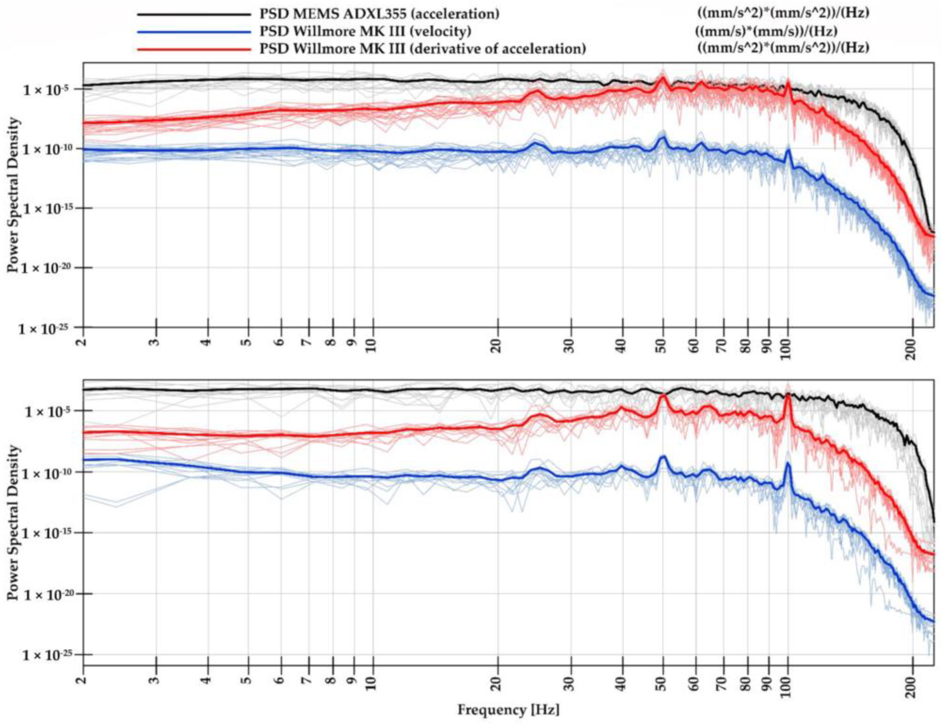
  105. Fuławka, K.; Mertuszka, P.; Szumny, M.; Stolecki, L.; Szczerbiński, K. Application of MEMS-Based Accelerometers for Near-Field Monitoring of Blasting-Induced Seismicity. Minerals 2022, 12, 533. [Google Scholar] [CrossRef]
Figure 1. The schematic presentation of the room-and-pillar mining system with roof deflection.
Energies 15 08312 g001
Figure 2. Number of accidents caused by rock falls and rockburst in Polish underground mines in the last 5 years.
Energies 15 08312 g002
Figure 3. Indicators of the roof fall disintegration based on [33].
Energies 15 08312 g003
Figure 4. Scheme of the borehole camera system.
Energies 15 08312 g004
Figure 5. Exemplary scheme of instrumented rock bolt with strain gauges installed on the three measurement levels.
Energies 15 08312 g005
Figure 6. Example of the axial stress measurement performed with the 5-level instrumented rock bolt.
Energies 15 08312 g006
Figure 7. Scheme of the vibrating wire strain gauge [44].
Energies 15 08312 g007
Figure 8. Scheme of different types of monitoring systems using optical fiber sensors.
Energies 15 08312 g008
Figure 9. Scheme of the three point extensometer.
Energies 15 08312 g009
Figure 10. Inclinometric sensor with a wireless data transmitter.
Energies 15 08312 g010
Figure 11. Graphic representation of the criterion to assess the stability of the roof layers.
Energies 15 08312 g011
Figure 12. An exemplary case of ground failure prediction with the use of an inclinometric sensor.
Energies 15 08312 g012
Figure 13. A spatial model of the mine workings was generated using laser scanning [21].
Energies 15 08312 g013
Figure 14. The most commonly used numerical methods in the evaluation of the stability of underground workings.
Energies 15 08312 g014
Figure 15. Distribution of the SF values within the immediate roof strata in the selected mining area (size of the model 2 km × 2 km × 1.5 km).
Energies 15 08312 g015
Figure 16. The contour of the displacement magnitude excavated in the rock salt chamber.
Energies 15 08312 g016
Figure 17. Simulated velocity distribution of the ejected rock mass along the tunnel supported by different types of rock bolt [88].
Energies 15 08312 g017
Figure 18. An artificial neural network.
Energies 15 08312 g018
Figure 19. Evaluation of rock mass propensity to failure based on developed roof fall hazard index (left) and evaluation of roof stability—categories of roof fall hazard (right) [24].
Energies 15 08312 g019
Figure 20. Key directions of mining digitalization according to Industry 4.0.
Energies 15 08312 g020
Figure 21. Rock bolt with an integrated sensor developed within the scope of the IlluMINEation project.
Energies 15 08312 g021
Figure 22. The PSD of noise was recorded by a mine seismometer and MEMS accelerometer in the horizontal (top) and vertical (bottom) directions [104].
Energies 15 08312 g022
Figure 23. Key aspects of successful roof fall hazard risk management.
Energies 15 08312 g023
Table 1. Successful cases of IIoT implementation in mining [101].
Mining Company NameDescriptionBenefits
Rio Tinto—Koodaideri iron ore project, AustraliaRio Tinto’s Kookaideri project in Australia is set to build the world’s first “intelligent mine” where all assets are networked together and are capable of making decisions in microsecondsBased on continuous monitoring the real-time decision are made what led to optimizing of production process
Hecla Mining Company—Casa Berardi mine, CanadaThe mine introduced Newtrax’s Mobile Equipment Telemetry in order to better manage machine downtime. Daily operation of machines’ time increased
Hindustan Zinc’s Sindesar Khurd (SK) mine, IndiaNewtrax MET integrated with the Sandvik OptiMine digital platform to track and receive data from the entire underground operation including drills, loaders, trucks, and other equipment.The effectiveness of production process increased
Goldcorp—Porcupine Gold Mine’s Borden site, CanadaWith a Ventilation on Demand system, Goldcorp can automatically adjust underground ventilation by controlling fans remotely through a centralized digital interface on the surface.The operation’s electrical consumption was reduced by 50% what significantly reduced cost.
Glencore’s Matagami Zinc mine, Canada Newtrax’s Mobile Equipment Telemetry provides mine operations with essential data from interconnected assets and equipment. The average tonnage of ore hauled in each trip has risen by about 10%.
Publisher’s Note: MDPI stays neutral with regard to jurisdictional claims in published maps and institutional affiliations.

