
A Critical Review on Charging Technologies of Electric Vehicles


 and
and 
Abstract
:1. Introduction
2. EV Converter Topology
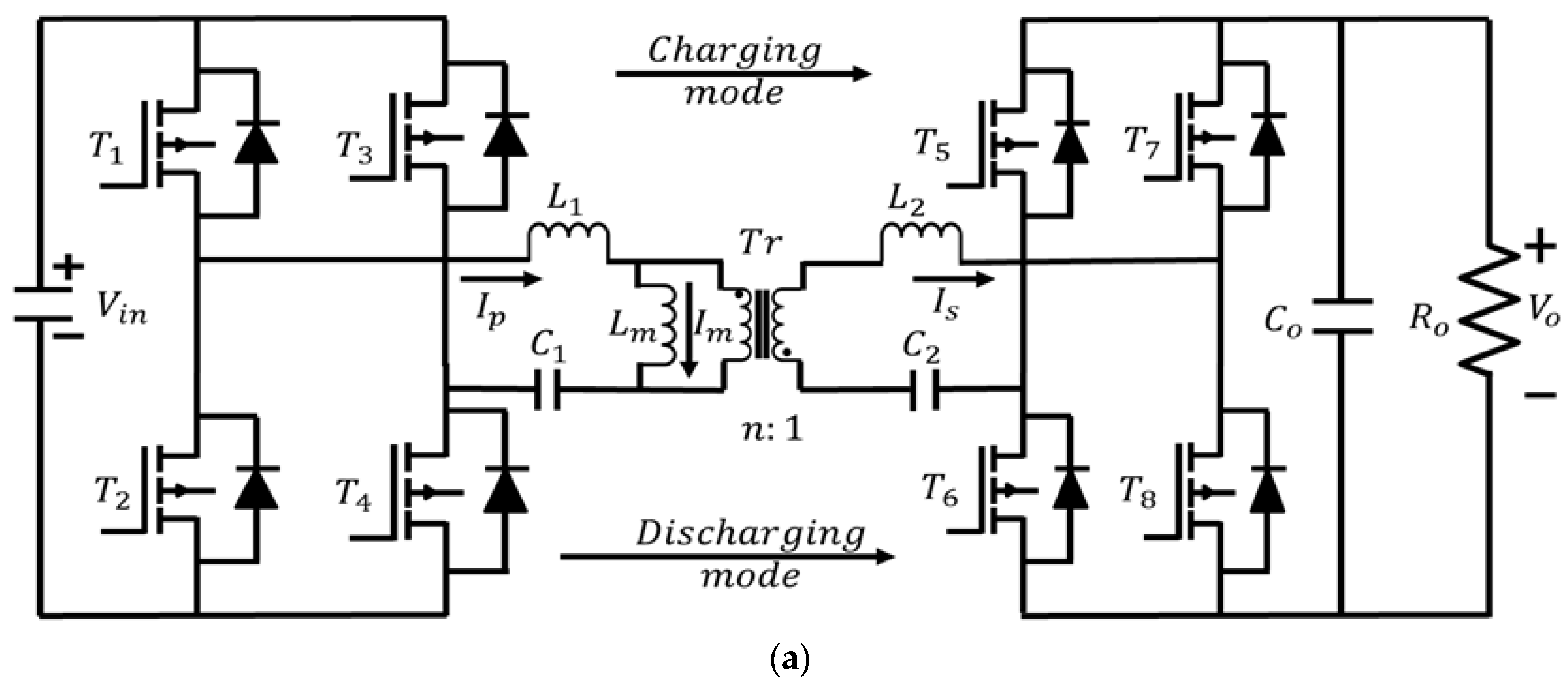
2.1. Development Trend of DC-DC Converter

| Ref. | Topology | Power Flow | Number of Switches | Passive Elements | Battery-Side Filter | Output Voltage Range | Rated Power | Switching Frequency | Efficiency |
|---|---|---|---|---|---|---|---|---|---|
| [47] | DAB | Bi-directional | 8 MOSFETs with body diode | , , , , , | C | 220 V to 447 V | 2 kW | ≥100 kHz | 90% |
| [47] | SRC | Bi-directional | 10 MOSFETs with body diode | , , , , , | LC | 220 V to 447 V | 2 kW | ≥100 kHz | 88% |
| [48] | Resonant dual active bridge (RDAB) | Bi-directional | 6 IGBTs with free-wheeling diode | , , | None | unknown | 2.5 kW | unknown | 96% |
| [48] | DAB | Bi-directional | 8 MOSFETs with body diode | , , snubber capacitor across each switch | C | 600 V | 5 kW | 20 kHz | 86% |
| [60] | DAHB | Bi-directional | 6 MOSFETs with body diode | , , , , , , snubber capacitor across each switch | C | 330 V | 600 W | 100 kHz | unknown |
| [61] | DAB | Bi-directional | 10 MOSFETs with body diode | , , | C | 340 V to 380 V | 800 W | 32 kHz | 92.9% & 93.4% with light & heavy load |
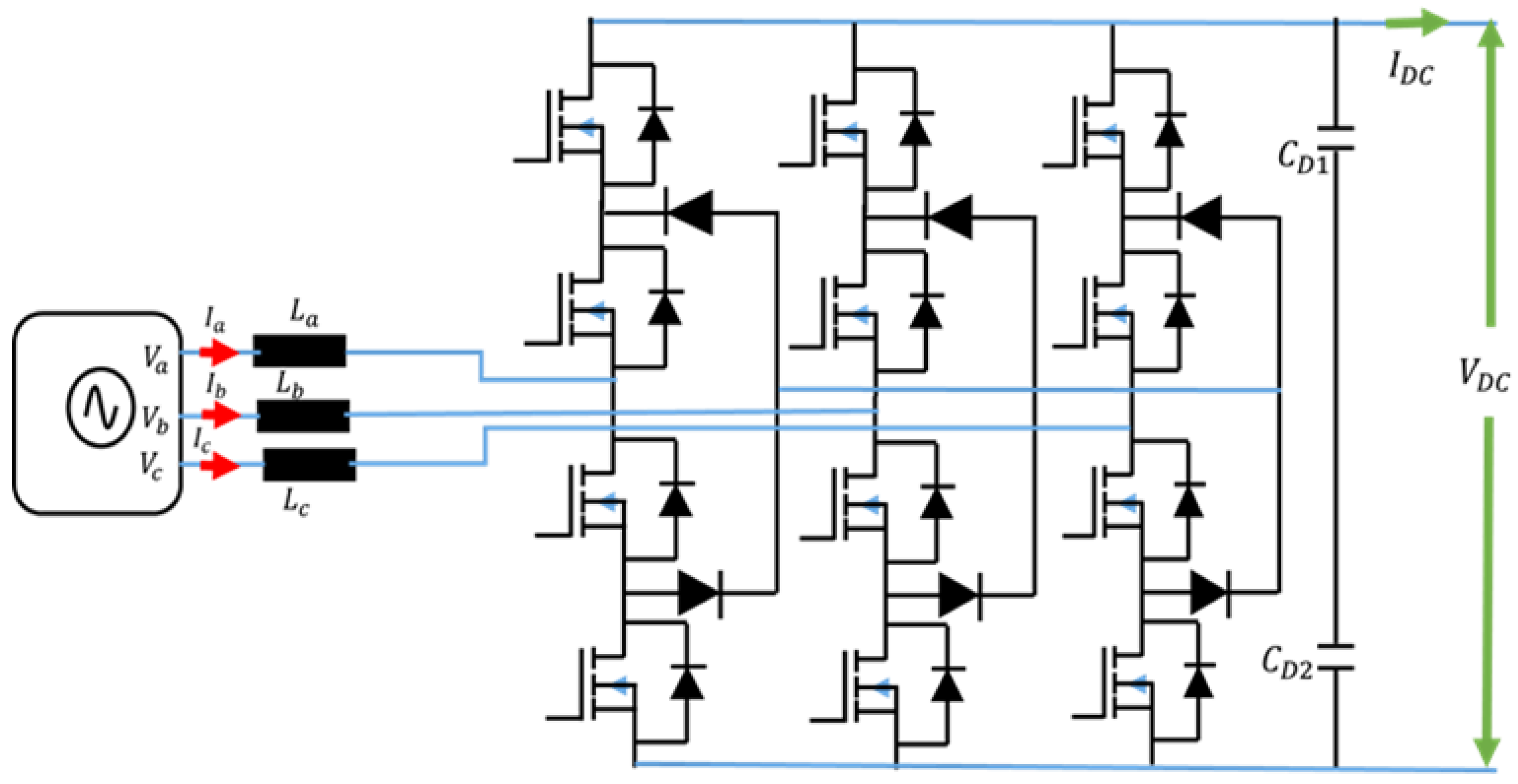
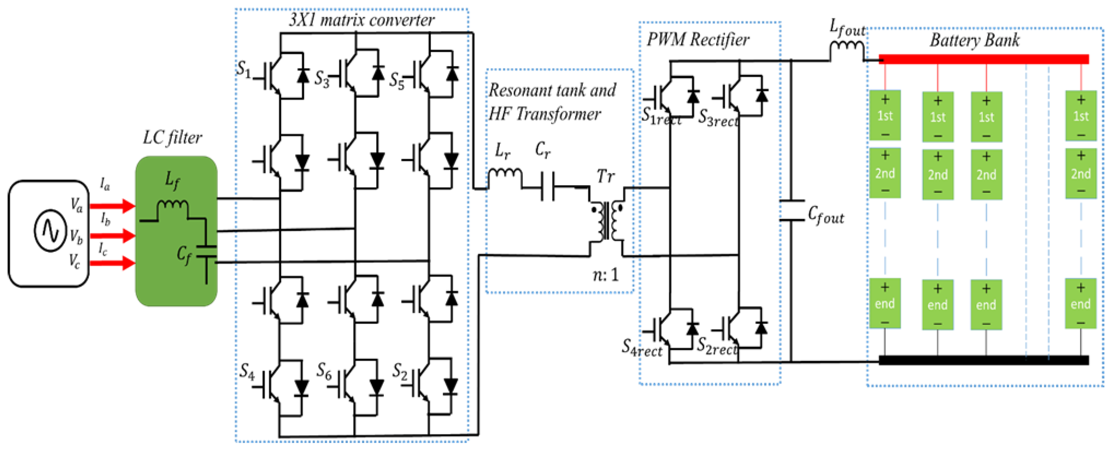
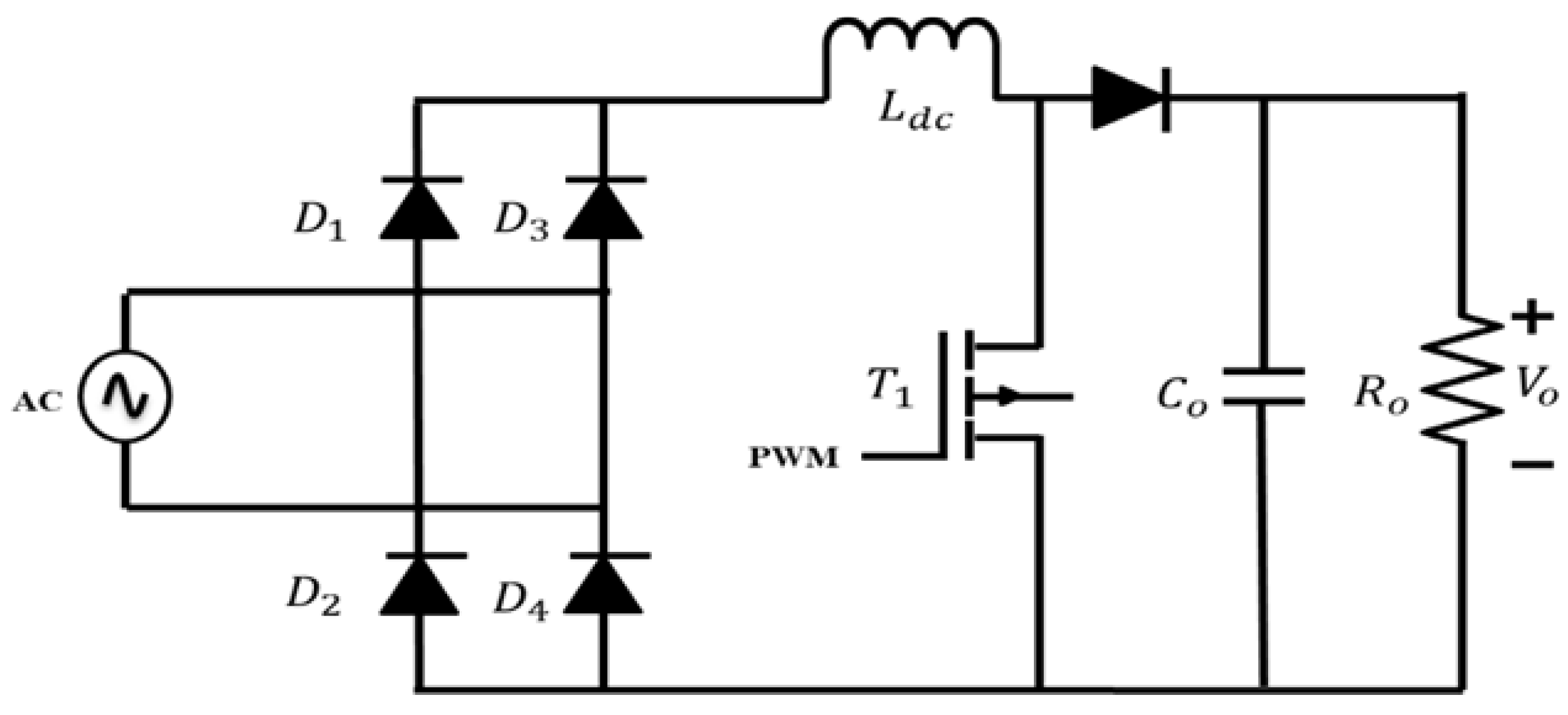
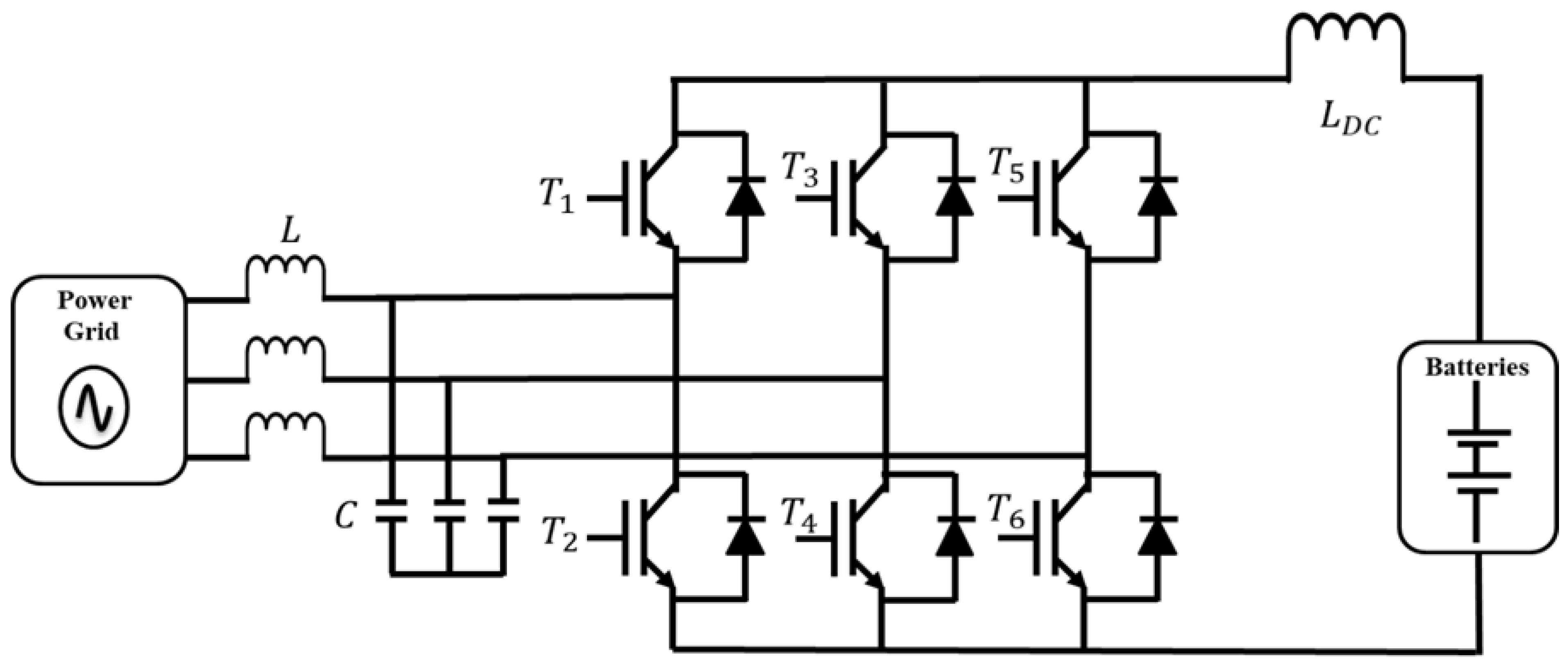
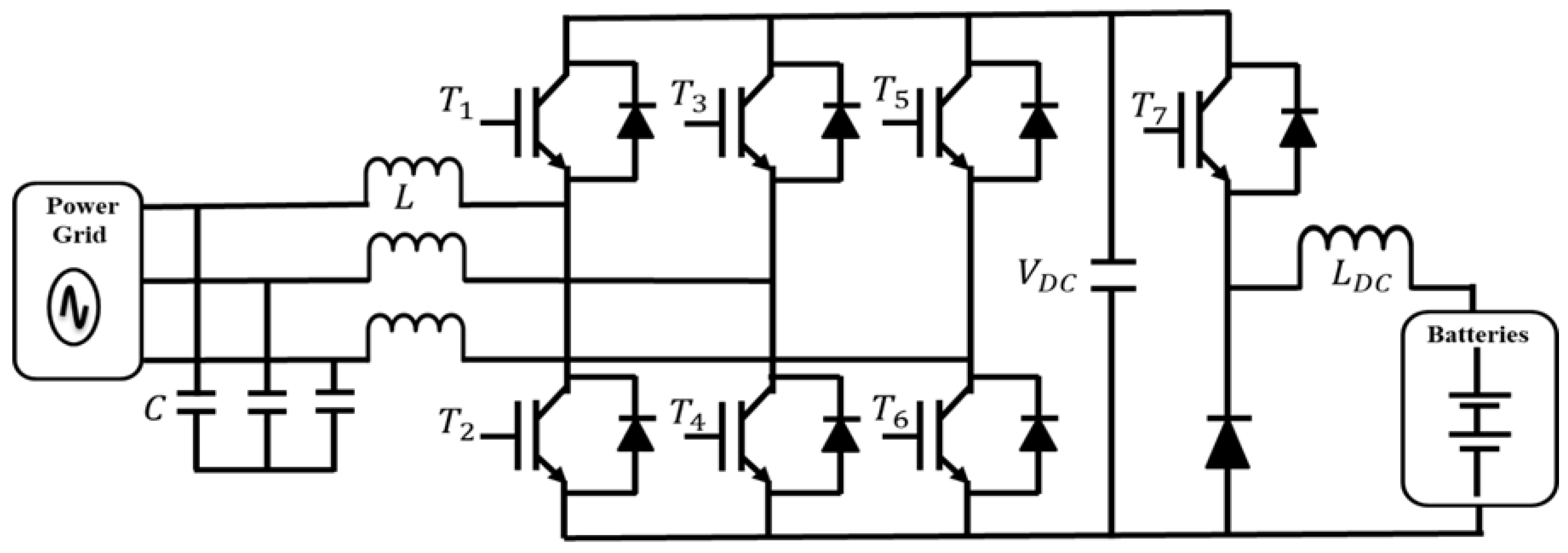
2.2. Development Trend of AC-DC Converter
3. EV Converter Reliability
- I.
- The customer’s standpoint.
- II.
- The manufacturer’s standpoint.
- III.
- The seller’s standpoint.
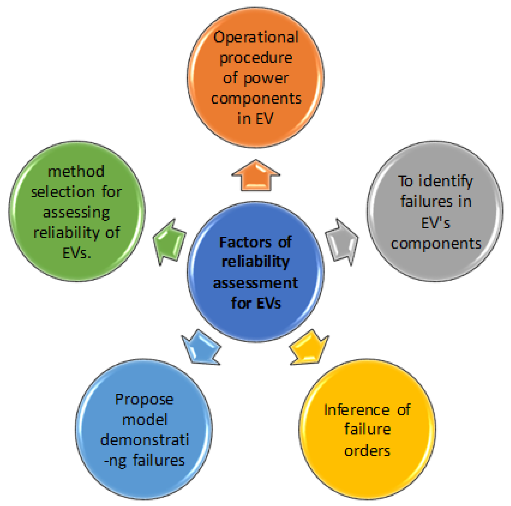
3.1. Reliability Evaluation for Evs
3.2. Converter Reliability Assessment for Evs
3.3. Future EV Converter Research Trend
- I.
- The design methods of electrical optimization using wide bandgap semiconductor (WBGS)-based topology to exploit their temperature, frequency, and low-loss characteristics [85].
- II.
- A focus on the design phase is required to consider reliability during production.
- III.
- To use mechanical optimization design methods to improve efficiency, power density, modularity, and reliability.
- IV.
- Moving toward high-fidelity, multi-functionality, scalability, and modularity to achieve high efficiency and power density through intelligent control and management techniques [86].
- V.
- To apply various control and optimization techniques such as fuzzy logic, artificial neural networks (ANNs), genetic algorithms, etc., to optimize several parameters of the converter.
- VI.
- To develop a high-fidelity model of the DC-DC converter that can design and validate interfaces for next-generation developers.
- VII.
- Handling the capability of electronic products (i.e., converter) by developing a modular design methodology.
- VIII.
- Advanced converters are required to be developed and optimized to accept fast-charging methods such as pulse-charging EV batteries. Control systems can also be employed for monitoring battery health and optimizing the charging process [19].
- IX.
- A systems-level approach can be developed that can be associated with new fast-charging technologies [19].
- X.
- A complete drain and charge cycle can damage the battery’s health. Therefore, further research is required to meet the optimal combination in terms of the dissipation and charging of the battery [19].
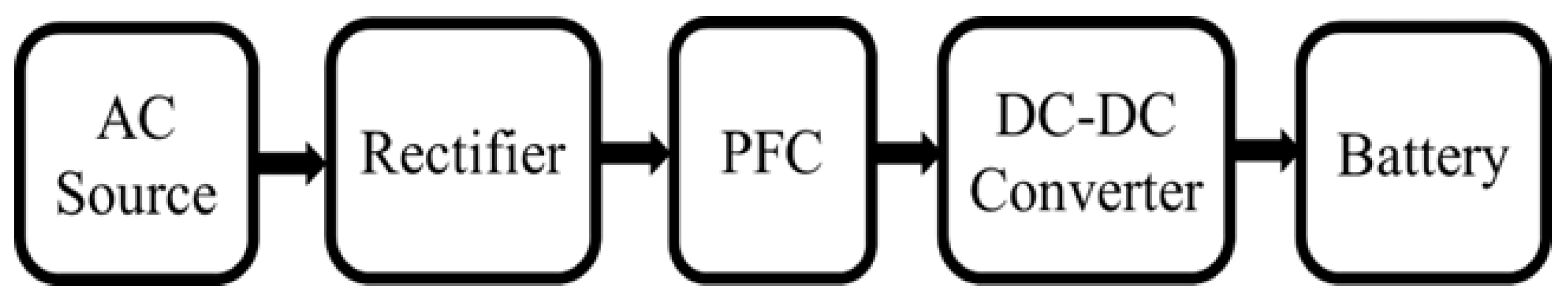
4. EV Charging
4.1. Charging Methods
- Constant Current (CC) Charge: In this method, the battery reaches the pre-set threshold cell voltage via the constant charging current and then slows down. During the CC mode, the high charging current introduces heat loss and thus pushes the thermal limit and accelerates the aging phenomena [87,88].
- Constant Voltage Charge: In this method, the charging current gradually increases and reaches the steady-state voltage equivalent to the battery voltage. When almost reaching the battery voltage, the current also gradually decreases. The key benefit is a short charging time and easy control. At the same time, the demerit is that the battery cannot be fully charged. The initially high charging current will cause joule heating in the battery and increase the battery temperature, which could lead to battery aging and degradation [88].
- Pulse charge: Using a pulse current, the battery can be charged fast with a drastically shortened charging duration. The demerit is that the quick-charging method can affect the battery’s health [88]. Examples of pulse current charging features are given in [89]. More refined research regarding the optimal charging waveform parameters (e.g., frequency, magnitude, and duty ratio of the charging current) is illustrated in [16].
- Boost charging: In this technique, the battery charger can draw a high current for a short time. The 4C rate is implemented in [90].
- Ohmic drop compensation: In this method, in the beginning, it increases the pre-set cell voltage threshold and takes the ohmic drop resistance of the battery into consideration. The highest 6C rate can be achieved [91].
- Linearly decreasing current (LDC) charging: In the LDC, the charging current is decreased linearly depending on the SOC of the battery pack. The initial SOC will be taken into account [92].
- Multistage charging: Three or more charging stages consisting of multistage currents are adopted based on the battery model [92].
4.2. Charging Strategies
| Ref. | Stages | Power Flow | Switching Frequency | Efficiency | Power Factor | Power Level | THD | System Volume/Mass | Output Voltage |
|---|---|---|---|---|---|---|---|---|---|
| [119] | First stage is a boost ac–dc converter Second stage is an isolated dc–dc converter | Unidirectional | 200 kHz | 95% | 0.996 | 6.1 kW | 4.2% | 1.2 L/1.6 kg | 400 V |
| [94] | First stage is interleaved PFC contains two CCM boost converters in parallel. Second stage is isolated Full-Bridge DC-DC Converter | Unidirectional | 70 kHz for PFC & 200 kHzfor DC-DC converter | 93.6% | >0.99 | 3.3 kW | <5% | 5.46 L/6.2 kg | 200 V to 450 V |
| [103] | A full-bridge LLC resonant converter A boost PFC converter | Unidirectional | 90 kHz for resonant & 45 kHz for PFC converter | 92.5% & 88.3% for 220 Vac for 110 Vac input voltage | >0.93 | 3.3 kW | Unknown | 7.1 L/6.8 kg | 150 V to 450 V |
| [120] | A full-bridge AC-DC converter A CLLLC DC-DC converter | Bidirectional | Unknown | 94.5% | Unknown | 3.3 KW | Unknown | Unknown | 250 V to 450 V |
| [121] | A totem-pole bridgeless PFC rectifier A CLLC resonant converter | Bidirectional | 300 kHz for AC-DC & 500 kHz for DC-DC converter | >96% | Unknown | 6.6 KW | Unknown | Unknown | 250 V to 450 V |
4.3. Charging Challenges and Potential Solutions
4.3.1. Thermal Management
| Ref. | Thermal Management Strategy | Battery Type | Findings |
|---|---|---|---|
| [128] | Reciprocating air flow | Cylindrical Li-ion | Lower maximum cell temperature and cell temperature difference due to shorter reciprocating period. Cell temperature is decreased with reduced transverse and higher longitudinal spacing. With charge/discharge rate, the maximum cell temperature rises quadratically. |
| [130] | Air and liquid type TMS | Cylindrical Li-ion | For the air TMS, a broad battery module with small cell-to-cell gap is suitable. For a liquid TMS, a narrow battery module with a small gap is appropriate. For high heat load conditions, the power consumption of air TMS is more than liquid TMS. |
| [134] | Forced air-cooling | Li-ion | Convection and advection of two heat transfer methods are performed to evaluate the cooling performance. Small hydraulic diameter alongside high coolant flow rate enhances the cooling performance but increases fan operating power. |
| [137] | Forced liquid cooling | Bipolar Li-ion | Higher coolant plate thickness and coolant velocity aid in retaining the temperature non-uniformity, and maximum temperature is closely controlled. Average temperature increases with number of cells among the coolant plates along with growing discharge rates. Increasing the coolant velocity decreases the average temperature. |
| [143] | Phase change materials (PCM) | Li-ion | Maximum temperature and temperature spread in the cell are decreased with PCM. During transient conditions of cooling system, the PCM on cell temperature is more noticeable. Higher PCM thickness around the cell offers improved cooling in the cell due to higher depth in curvature. |
| [134] | Air cooling | Prismatic Li-ion | Higher flow rate of the fan and lower gap spacing cause a decline in the maximum temperature growth. Uneven gap spacing influences the temperature circulations but does not affect the maximum temperature growth. Constant gap spacing decreases both the overall temperature uniformity and the maximum temperature growth. |
| [145] | Phase change materials | Li-ion | Under stressed and normal conditions, it is probable to attain uniform temperatures with passive TMS. The absorption and conduction of heat via the PCM–graphite matrix avoid circulation of thermal runaway. |
| [141] | Heat pipe cooling | Li-ion | Addition of heat pipe decreased the thermal resistance of a heat sink. Flat heat pipe operates efficiently under diverse grade road conditions. Heat pipe managed instantaneous rises of the heat flux more efficiently than conventional heat sink under high-frequency condition. |
| [142] | Heat pipe and wet cooling combined TMS | Li-ion | Natural convection cooling system is not suggested for the battery discharged at high rate because of the large temperature gradient and high temperature inside the battery toward the last part of discharge. Heat pipe TMS cooling by water bath is not recommended owing to the buildup of bubbles throughout the discharge. |
| [137] | Liquid-cooling | Li-ion | Growing inlet mass circulation can efficiently constrain the maximum temperature. Temperature is proportional to the inlet temperature and inversely proportional to the width of cooling plate. Width of cooling plate, inlet mass flow rate, and inlet temperature are three factors analyzed for better solutions. |
4.3.2. Vehicle to GRID (V2G)
5. Conclusions
- To date, the impacts of fast charging on battery health and battery aging have not been identified. Battery failure mechanisms due to localized high current density have not yet been elucidated. Appropriate thermal challenges have not been addressed.
- An efficient charging converter is key to achieving the required charging within a 5–10 min range. Various alternative approaches have been identified for fast-charging technologies; however, much remains to be investigated regarding the fast-charging converter, converter reliability, control scheme, and wide-bandgap semiconductor device potentiality in the converter architecture and possible degradation mechanisms in battery and semiconductor switches.
- The behavior of fast-charging technologies in cold climates has still not been investigated, and the approach to charging optimization is not fully clear yet.
- While much attention has already been paid to developing a fast-charging topology, further research is required to investigate the impact of fast charging on battery health and determine how the generated heat load on the battery at the cell and pack levels can be managed. We must also determine how a cooling system can be integrated with EVs, with the constraints of cost and weight.
- Finally, cell-level and pack-level degradations are not well understood. Since the battery’s operating window is narrow, it is highly recommended to study the degradation behavior under different operating conditions. Few modelling works were found, but most are at the cell level. It needs to be extended up to the module and pack levels. Multiscale multiphysics modelling can help researchers to identify those challenges and support EV manufacturers to adopt a safe charging protocol with high reliability.
Author Contributions
Funding
Institutional Review Board Statement
Informed Consent Statement
Data Availability Statement
Conflicts of Interest
References
- De Santiago, J.; Bernhoff, H.; Ekergård, B.; Eriksson, S.; Ferhatovic, S.; Waters, R.; Leijon, M. Electrical Motor Drivelines in Commercial All-Electric Vehicles: A Review. IEEE Trans. Veh. Technol. 2011, 61, 475–484. [Google Scholar] [CrossRef] [Green Version]
- Bose, B.K. Global Energy Scenario and Impact of Power Electronics in 21st Century. IEEE Trans. Ind. Electron. 2012, 60, 2638–2651. [Google Scholar] [CrossRef]
- Haghbin, S.; Lundmark, S.; Alakula, M.; Carlson, O. Grid-Connected Integrated Battery Chargers in Vehicle Applications: Review and New Solution. IEEE Trans. Ind. Electron. 2012, 60, 459–473. [Google Scholar] [CrossRef]
- Sanguesa, J.; Torres-Sanz, V.; Garrido, P.; Martinez, F.; Marquez-Barja, J. A Review on Electric Vehicles: Technologies and Challenges. Smart Cities 2021, 4, 372–404. [Google Scholar] [CrossRef]
- Zhao, J.; Xi, X.; Na, Q.; Wang, S.; Kadry, S.N.; Kumar, P.M. The technological innovation of hybrid and plug-in electric vehicles for environment carbon pollution control. Environ. Impact Assess. Rev. 2020, 86, 106506. [Google Scholar] [CrossRef]
- Rajashekara, K. Present Status and Future Trends in Electric Vehicle Propulsion Technologies. IEEE J. Emerg. Sel. Top. Power Electron. 2013, 1, 3–10. [Google Scholar] [CrossRef]
- Chen, T.; Zhang, X.-P.; Wang, J.; Li, J.; Wu, C.; Hu, M.; Bian, H. A Review on Electric Vehicle Charging Infrastructure Development in the UK. J. Mod. Power Syst. Clean Energy 2020, 8, 193–205. [Google Scholar] [CrossRef]
- Hemavathi, S.; Shinisha, A. A study on trends and developments in electric vehicle charging technologies. J. Energy Storage 2022, 52, 105013. [Google Scholar] [CrossRef]
- Lee, J.-Y.; Chae, H.-J. 6.6-kW Onboard Charger Design Using DCM PFC Converter With Harmonic Modulation Technique and Two-Stage DC/DC Converter. IEEE Trans. Ind. Electron. 2013, 61, 1243–1252. [Google Scholar] [CrossRef]
- Amjadi, Z.; Williamson, S.S. Power-Electronics-Based Solutions for Plug-in Hybrid Electric Vehicle Energy Storage and Management Systems. IEEE Trans. Ind. Electron. 2009, 57, 608–616. [Google Scholar] [CrossRef]
- Rafi, A.H.; Bauman, J. A Comprehensive Review of DC Fast-Charging Stations with Energy Storage: Architectures, Power Converters, and Analysis. IEEE Trans. Transp. Electrification 2020, 7, 345–368. [Google Scholar] [CrossRef]
- EV Penetration to be 30% by 2030: Study|The Financial Express. Available online: https://www.financialexpress.com/express-mobility/vehicles/electric-vehicles/ev-penetration-to-be-30-by-2030-study/2565092/ (accessed on 13 August 2022).
- Sreeram, K.; Preetha, P.K.; Poornachandran, P. Electric Vehicle Scenario in India: Roadmap, Challenges and Opportunities. In Proceedings of the 2019 IEEE International Conference on Electrical, Computer and Communication Technologies (ICECCT), Coimbatore, India, 20–22 February 2019. [Google Scholar]
- Berckmans, G.; Messagie, M.; Smekens, J.; Omar, N.; Vanhaverbeke, L.; Van Mierlo, J. Cost Projection of State of the Art Lithium-Ion Batteries for Electric Vehicles Up to 2030. Energies 2017, 10, 1314. [Google Scholar] [CrossRef] [Green Version]
- Lee, J.-H.; Moon, J.-S.; Lee, Y.-S.; Kim, Y.-R.; Won, C.-Y. Fast charging technique for EV battery charger using three-phase AC-DC boost converter. In Proceedings of the IECON 2011—37th Annual Conference of the IEEE Industrial Electronics Society, Melbourne, Australia, 7–10 November 2011; pp. 4577–4582. [Google Scholar] [CrossRef]
- Di Yin, M.; Cho, J.; Park, D. Pulse-Based Fast Battery IoT Charger Using Dynamic Frequency and Duty Control Techniques Based on Multi-Sensing of Polarization Curve. Energies 2016, 9, 209. [Google Scholar] [CrossRef]
- Lee, J.H.; Chakraborty, D.; Hardman, S.J.; Tal, G. Exploring electric vehicle charging patterns: Mixed usage of charging infrastructure. Transp. Res. Part D Transp. Environ. 2020, 79, 102249. [Google Scholar] [CrossRef]
- Hardman, S.; Jenn, A.; Tal, G.; Axsen, J.; Beard, G.; Daina, N.; Figenbaum, E.; Jakobsson, N.; Jochem, P.; Kinnear, N.; et al. A review of consumer preferences of and interactions with electric vehicle charging infrastructure. Transp. Res. Part D: Transp. Environ. 2018, 62, 508–523. [Google Scholar] [CrossRef] [Green Version]
- Collin, R.; Miao, Y.; Yokochi, A.; Enjeti, P.; von Jouanne, A. Advanced Electric Vehicle Fast-Charging Technologies. Energies 2019, 12, 1839. [Google Scholar] [CrossRef] [Green Version]
- Yilmaz, M.; Krein, P.T. Review of battery charger topologies, charging power levels, and infrastructure for plug-in electric and hybrid vehicles. IEEE Trans. Power Electron. 2013, 28, 2151–2169. [Google Scholar] [CrossRef]
- Mishra, S.; Verma, S.; Chowdhury, S.; Gaur, A.; Mohapatra, S.; Dwivedi, G.; Verma, P. A Comprehensive Review on Developments in Electric Vehicle Charging Station Infrastructure and Present Scenario of India. Sustainability 2021, 13, 2396. [Google Scholar] [CrossRef]
- Morrow, K.; Karner, D.; Francfort, J. Plug-in Hybrid Electric Vehicle Charging Infrastructure Review Final Report Battelle Energy Alliance Contract No. 58517. 2008. Available online: https://wecanfigurethisout.org/ENERGY/Lecture_notes/Electrification_of_Tranportation_Supporting_Materials%20/INL%20-%20PHEV%20infrastructure%20review.pdf (accessed on 1 July 2022).
- Hildermeier, J.; Kolokathis, C.; Rosenow, J.; Hogan, M.; Wiese, C.; Jahn, A. Smart EV Charging: A Global Review of Promising Practices. World Electr. Veh. J. 2019, 10, 80. [Google Scholar] [CrossRef]
- Das, H.S.; Rahman, M.M.; Li, S.; Tan, C.W. Electric vehicles standards, charging infrastructure, and impact on grid integration: A technological review. Renew. Sustain. Energy Rev. 2020, 120, 109618. [Google Scholar] [CrossRef]
- Abraham, D.S.; Verma, R.; Kanagaraj, L.; Raman, S.G.T.; Rajamanickam, N.; Chokkalingam, B.; Sekar, K.M.; Mihet-Popa, L. Electric Vehicles Charging Stations’ Architectures, Criteria, Power Converters, and Control Strategies in Microgrids. Electronics 2021, 10, 1895. [Google Scholar] [CrossRef]
- Arif, S.; Lie, T.; Seet, B.; Ayyadi, S.; Jensen, K. Review of Electric Vehicle Technologies, Charging Methods, Standards and Optimization Techniques. Electronics 2021, 10, 1910. [Google Scholar] [CrossRef]
- Khalid, M.R.; Khan, I.A.; Hameed, S.; Asghar, M.S.J.; Ro, J.-S. A Comprehensive Review on Structural Topologies, Power Levels, Energy Storage Systems, and Standards for Electric Vehicle Charging Stations and Their Impacts on Grid. IEEE Access 2021, 9, 128069–128094. [Google Scholar] [CrossRef]
- Xuan, Y.; Yang, X.; Chen, W.; Liu, T.; Hao, X. A Novel Three-Level CLLC Resonant DC–DC Converter for Bidirectional EV Charger in DC Microgrids. IEEE Trans. Ind. Electron. 2020, 68, 2334–2344. [Google Scholar] [CrossRef]
- Rajendran, G.; Vaithilingam, C.A.; Misron, N.; Naidu, K.; Ahmed, R. A comprehensive review on system architecture and international standards for electric vehicle charging stations. J. Energy Storage 2021, 42, 103099. [Google Scholar] [CrossRef]
- Wu, J.; Li, S.; Tan, S.-C.; Hui, S.Y.R. Capacitor-Clamped LLC Resonant Converter Operating in Capacitive Region for High-Power-Density EV Charger. IEEE Trans. Power Electron. 2021, 36, 11456–11468. [Google Scholar] [CrossRef]
- Choi, S.-W.; Oh, S.-T.; Kim, M.-W.; Lee, I.-O.; Lee, J.-Y. Interleaved Isolated Single-Phase PFC Converter Module for Three-Phase EV Charger. IEEE Trans. Veh. Technol. 2020, 69, 4957–4967. [Google Scholar] [CrossRef]
- Lara, J.; Masisi, L.; Hernandez, C.; Arjona, M.; Chandra, A. Novel Five-Level ANPC Bidirectional Converter for Power Quality Enhancement during G2V/V2G Operation of Cascaded EV Charger. Energies 2021, 14, 2650. [Google Scholar] [CrossRef]
- Pandey, R.; Singh, B. A Power Factor Corrected Resonant EV Charger Using Reduced Sensor Based Bridgeless Boost PFC Converter. IEEE Trans. Ind. Appl. 2021, 57, 6465–6474. [Google Scholar] [CrossRef]
- Blaabjerg, F.; Wang, H.; Vernica, I.; Liu, B.; Davari, P. Reliability of Power Electronic Systems for EV/HEV Applications. Proc. IEEE 2020, 109, 1060–1076. [Google Scholar] [CrossRef]
- Wen, H.; Li, J.; Shi, H.; Hu, Y.; Yang, Y. Fault Diagnosis and Tolerant Control of Dual-Active-Bridge Converter With Triple-Phase Shift Control for Bidirectional EV Charging Systems. IEEE Trans. Transp. Electrif. 2020, 7, 287–303. [Google Scholar] [CrossRef]
- Samavatian, V.; Fotuhi-Firuzabad, M.; Dehghanian, P.; Blaabjerg, F. Reliability Modeling of Multistate Degraded Power Electronic Converters with Simultaneous Exposure to Dependent Competing Failure Processes. IEEE Access 2021, 9, 67096–67108. [Google Scholar] [CrossRef]
- Chakraborty, S.; Hasan, M.M.; Tran, D.D.; Jaman, S.; Bossche, P.V.D.; El Baghdadi, M.; Hegazy, O. Reliability Assessment of a WBG-based Interleaved Bidirectional HV DC/DC Converter for Electric Vehicle Drivetrains. In Proceedings of the 2020 Fifteenth International Conference on Ecological Vehicles and Renewable Energies (EVER), Monte-Carlo, Monaco, 10–12 September 2020; pp. 1–8. [Google Scholar] [CrossRef]
- Li, Y.; Li, K.; Xie, Y.; Liu, J.; Fu, C.; Liu, B. Optimized charging of lithium-ion battery for electric vehicles: Adaptive multistage constant current–constant voltage charging strategy. Renew. Energy 2019, 146, 2688–2699. [Google Scholar] [CrossRef]
- Garg, A.; Das, M. High Efficiency Three Phase Interleaved Buck Converter for Fast Charging of EV. In Proceedings of the 2021 1st International Conference on Power Electronics and Energy (ICPEE), Bhubaneswar, India, 2–3 January 2021; pp. 1–5. [Google Scholar] [CrossRef]
- Rathore, V.; Siddavatam, R.P.R.; Rajashekara, K. An Isolated Multilevel DC-DC Converter Topology with Hybrid Resonant Switching for EV Fast Charging Application. IEEE Trans. Ind. Appl. 2022, 58, 5546–5557. [Google Scholar] [CrossRef]
- Pareek, S.; Sujil, A.; Ratra, S.; Kumar, R. Electric Vehicle Charging Station Challenges and Opportunities: A Future Perspective. In Proceedings of the 2020 International Conference on Emerging Trends in Communication, Control and Computing (ICONC3), Lakshmangarh, India, 21–22 February 2020; pp. 1–6. [Google Scholar] [CrossRef]
- Sovacool, B.K.; Kester, J.; Noel, L.; de Rubens, G.Z. Actors, business models, and innovation activity systems for vehicle-to-grid (V2G) technology: A comprehensive review. Renew. Sustain. Energy Rev. 2020, 131, 109963. [Google Scholar] [CrossRef]
- Huda, M.; Koji, T.; Aziz, M. Techno Economic Analysis of Vehicle to Grid (V2G) Integration as Distributed Energy Resources in Indonesia Power System. Energies 2020, 13, 1162. [Google Scholar] [CrossRef]
- Basso, T.S.; DeBlasio, R. IEEE 1547 Series of Standards: Interconnection Issues. IEEE Trans. Power Electron. 2004, 19, 1159–1162. [Google Scholar] [CrossRef] [Green Version]
- Lee, B.-K.; Kim, J.-P.; Kim, S.-G.; Lee, J.-Y. An Isolated/Bidirectional PWM Resonant Converter for V2G(H) EV On-Board Charger. IEEE Trans. Veh. Technol. 2017, 66, 7741–7750. [Google Scholar] [CrossRef]
- Zeljkovic, S.; Vuletic, R.; Miller, A.; Denais, A. A three phase bidirectional V2G interface converter based on SiC JFETs. In Proceedings of the 2015 17th European Conference on Power Electronics and Applications (EPE’15 ECCE-Europe), Geneva, Switzerland, 8–10 September 2015; pp. 1–10. [Google Scholar] [CrossRef]
- Krismer, F.; Biela, J.; Kolar, J. A comparative evaluation of isolated bi-directional DC/DC converters with wide input and output voltage range. In Proceedings of the Fourtieth IAS Annual Meeting. Conference Record of the 2005 Industry Applications Conference, Hong Kong, China, 2–6 October 2005; Volume 1, pp. 599–606. [Google Scholar]
- Twiname, R.P.; Thrimawithana, D.J.; Madawala, U.K.; Baguley, C.A. A New Resonant Bidirectional DC–DC Converter Topology. IEEE Trans. Power Electron. 2013, 29, 4733–4740. [Google Scholar] [CrossRef]
- Oggier, G.; Leidhold, R.; Garcia, G.; Oliva, A.; Balda, J.; Barlow, F. Extending the ZVS Operating Range of Dual Active Bridge High-Power DC-DC Converters. In Proceedings of the 2006 37th IEEE Power Electronics Specialists Conference, Jeju, Korea, 18–22 June 2006. [Google Scholar] [CrossRef]
- Oggier, G.G.; García, G.O.; Oliva, A.R. Switching Control Strategy to Minimize Dual Active Bridge Converter Losses. IEEE Trans. Power Electron. 2009, 24, 1826–1838. [Google Scholar] [CrossRef]
- Zhao, B.; Song, Q.; Liu, W. Efficiency Characterization and Optimization of Isolated Bidirectional DC–DC Converter Based on Dual-Phase-Shift Control for DC Distribution Application. IEEE Trans. Power Electron. 2012, 28, 1711–1727. [Google Scholar] [CrossRef]
- Oggier, G.G.; Garcia, G.O.; Oliva, A.R. Modulation strategy to operate the dual active bridge DC-DC converter under soft switching in the whole operating range. IEEE Trans. Power Electron. 2010, 26, 1228–1236. [Google Scholar] [CrossRef]
- Krismer, F.; Round, S.; Kolar, J.W. Performance Optimization of a High Current Dual Active Bridge with a Wide Operating Voltage Range. In Proceedings of the 2006 37th IEEE Power Electronics Specialists Conference, Jeju, Korea, 18–22 June 2006; pp. 1–7. [Google Scholar] [CrossRef] [Green Version]
- Krismer, F.; Kolar, J.W. Efficiency-Optimized High-Current Dual Active Bridge Converter for Automotive Applications. IEEE Trans. Ind. Electron. 2011, 59, 2745–2760. [Google Scholar] [CrossRef]
- Bai, H.; Mi, C. Eliminate Reactive Power and Increase System Efficiency of Isolated Bidirectional Dual-Active-Bridge DC–DC Converters Using Novel Dual-Phase-Shift Control. IEEE Trans. Power Electron. 2008, 23, 2905–2914. [Google Scholar] [CrossRef]
- Jain, A.K.; Ayyanar, R. Pwm control of dual active bridge: Comprehensive analysis and experimental verification. IEEE Trans. Power Electron. 2010, 26, 1215–1227. [Google Scholar] [CrossRef]
- Deng, J.; Li, S.; Hu, S.; Mi, C.C.; Ma, R. Design Methodology of LLC Resonant Converters for Electric Vehicle Battery Chargers. IEEE Trans. Veh. Technol. 2013, 63, 1581–1592. [Google Scholar] [CrossRef]
- He, P.; Khaligh, A. Comprehensive Analyses and Comparison of 1 kW Isolated DC–DC Converters for Bidirectional EV Charging Systems. IEEE Trans. Transp. Electrif. 2016, 3, 147–156. [Google Scholar] [CrossRef]
- Chakraborty, S.; Chattopadhyay, S. Fully ZVS, Minimum RMS Current Operation of the Dual-Active Half-Bridge Converter Using Closed-Loop Three-Degree-of-Freedom Control. IEEE Trans. Power Electron. 2018, 33, 10188–10199. [Google Scholar] [CrossRef]
- Ngo, T.; Won, J.; Nam, K. A single-phase bidirectional dual active half-bridge converter. In Proceedings of the 2012 Twenty-Seventh Annual IEEE Applied Power Electronics Conference and Exposition (APEC), Orlando, FL, USA, 5–9 February 2012; pp. 1127–1133. [Google Scholar] [CrossRef]
- Higa, H.; Takuma, S.; Orikawa, K.; Itoh, J.-I. Dual active bridge DC-DC converter using both full and half bridge topologies to achieve high efficiency for wide load. In Proceedings of the 2015 IEEE Energy Conversion Congress and Exposition (ECCE), Montreal, QC, Canada, 20–24 September 2015; pp. 6344–6351. [Google Scholar] [CrossRef]
- Singh, B.; Singh, B.N.; Chandra, A.; Al-Haddad, K.; Pandey, A.; Kothari, D.P. A Review of Three-Phase Improved Power Quality AC–DC Converters. IEEE Trans. Ind. Electron. 2004, 51, 641–660. [Google Scholar] [CrossRef]
- Zhang, H.; Yang, L.; Wang, S.; Puukko, J. Common-Mode EMI Noise Modeling and Reduction with Balance Technique for Three-Level Neutral Point Clamped Topology. IEEE Trans. Ind. Electron. 2017, 64, 7563–7573. [Google Scholar] [CrossRef]
- Jauch, F.; Biela, J. Modelling and ZVS control of an isolated three-phase bidirectional AC-DC converter. In Proceedings of the 2013 15th European Conference on Power Electronics and Applications (EPE), Lille, France, 2–6 September 2013; pp. 1–11. [Google Scholar] [CrossRef]
- Krishnamoorthy, H.S.; Garg, P.; Enjeti, P.N. A matrix converter-based topology for high power electric vehicle battery charging and V2G application. In Proceedings of the IECON 2012—38th Annual Conference on IEEE Industrial Electronics Society, Montreal, QC, Canada, 25–28 October 2012; pp. 2866–2871. [Google Scholar] [CrossRef]
- Varajão, D.; Miranda, L.M.; Araújo, R.E. Towards a new technological solution for community energy storage. In Proceedings of the 2014 16th European Conference on Power Electronics and Applications, Lappeenranta, Finland, 26–28 August 2014; pp. 1–10. [Google Scholar] [CrossRef] [Green Version]
- Friedli, T.; Kolar, J.W.; Rodriguez, J.; Wheeler, P.W. Comparative Evaluation of Three-Phase AC–AC Matrix Converter and Voltage DC-Link Back-to-Back Converter Systems. IEEE Trans. Ind. Electron. 2011, 59, 4487–4510. [Google Scholar] [CrossRef]
- Varajao, D.; Araujo, R.E.; Miranda, L.M.; Lopes, J.A.P. Modulation Strategy for a Single-Stage Bidirectional and Isolated AC–DC Matrix Converter for Energy Storage Systems. IEEE Trans. Ind. Electron. 2017, 65, 3458–3468. [Google Scholar] [CrossRef]
- Ahsan, M.; Hon, S.T.; Batunlu, C.; Albarbar, A. Reliability Assessment of IGBT Through Modelling and Experimental Testing. IEEE Access 2020, 8, 39561–39573. [Google Scholar] [CrossRef]
- Gandoman, F.H.; Ahmadi, A.; Bossche, P.V.D.; Van Mierlo, J.; Omar, N.; Nezhad, A.E.; Mavalizadeh, H.; Mayet, C. Status and future perspectives of reliability assessment for electric vehicles. Reliab. Eng. Syst. Saf. 2018, 183, 1–16. [Google Scholar] [CrossRef]
- Li, K.; Tian, G.Y.; Cheng, L.; Yin, A.; Cao, W.; Crichton, S. State Detection of Bond Wires in IGBT Modules Using Eddy Current Pulsed Thermography. IEEE Trans. Power Electron. 2013, 29, 5000–5009. [Google Scholar] [CrossRef] [Green Version]
- Zhang, G. Study on methods of electric vehicle safety test. In Proceedings of the 13th International Conference on Man-Machine-Environment System Engineering, Yantai, China, 21–25 October 2013; pp. 133–142. [Google Scholar]
- Baraldi, P.; Galarza, A.; Rigamonti, M.; Rantala, S.; Unanue, I.; Astigarraga, D.; Zio, E.; Maio, D.; Ruddle, A. A Procedure for Practical Prognostics and Health Monitoring of Fully Electric Vehicles for Enhanced Safety and Reliability. In Proceedings of the 5th IET Hybrid and Electric Vehicles Conference (HEVC 2014), London, UK, 5–6 November 2014. [Google Scholar] [CrossRef]
- Freschi, F.; Mitolo, M.; Tommasini, R. Electrical safety of electric vehicles. In Proceedings of the 2017 IEEE/IAS 53rd Industrial and Commercial Power Systems Technical Conference (I&CPS), Niagara Falls, ON, Canada, 6–11 May 2017. [Google Scholar] [CrossRef]
- Ghavami, M.; Essakiappan, S.; Singh, C. A framework for reliability evaluation of electric vehicle charging stations. In Proceedings of the 2016 IEEE Power and Energy Society General Meeting (PESGM), Boston, MA, USA, 17–21 July 2016; pp. 1–5. [Google Scholar] [CrossRef]
- Ghavami, M.; Singh, C. Reliability evaluation of plug-in hybrid electric vehicle chargers. In Proceedings of the 2017 IEEE International Conference on Environment and Electrical Engineering and 2017 IEEE Industrial and Commercial Power Systems Europe (EEEIC/I&CPS Europe), Milan, Italy, 6–9 June 2017; pp. 1–6. [Google Scholar] [CrossRef]
- Ghavami, M.; Singh, C. Reliability evaluation of electric vehicle charging systems including the impact of repair. In Proceedings of the 2017 IEEE Industry Applications Society Annual Meeting, Cincinnati, OH, USA, 1–5 October 2017; pp. 1–9. [Google Scholar] [CrossRef]
- Dhople, S.V.; Davoudi, A.; Domínguez-García, A.D.; Chapman, P.L. A Unified Approach to Reliability Assessment of Multiphase DC–DC Converters in Photovoltaic Energy Conversion Systems. IEEE Trans. Power Electron. 2010, 27, 739–751. [Google Scholar] [CrossRef]
- Zhuang, X.; Yadav, O.P. A new reliability assessment model for power electronic modules. In Proceedings of the 2015 IEEE International Conference on Industrial Engineering and Engineering Management (IEEM), Singapore, 6–9 December 2015; pp. 1012–1016. [Google Scholar] [CrossRef]
- Drobnik, J.; Jain, P. Electric and Hybrid Vehicle Power Electronics Efficiency, Testing and Reliability. World Electr. Veh. J. 2013, 6, 719–730. [Google Scholar] [CrossRef] [Green Version]
- Zeng, B.; Luo, Y.; Zhang, C.; Liu, Y. Assessing the Impact of an EV Battery Swapping Station on the Reliability of Distribution Systems. Appl. Sci. 2020, 10, 8023. [Google Scholar] [CrossRef]
- Reddy, K.J.; Natarajan, S. Energy sources and multi-input DC-DC converters used in hybrid electric vehicle applications—A review. Int. J. Hydrogen Energy 2018, 43, 17387–17408. [Google Scholar] [CrossRef]
- López, I.; Ibarra, E.; Matallana, A.; Andreu, J.; Kortabarria, I. Next generation electric drives for HEV/EV propulsion systems: Technology, trends and challenges. Renew. Sustain. Energy Rev. 2019, 114, 109336. [Google Scholar] [CrossRef]
- Chakraborty, S.; Vu, H.-N.; Hasan, M.M.; Tran, D.-D.; El Baghdadi, M.; Hegazy, O. DC-DC Converter Topologies for Electric Vehicles, Plug-in Hybrid Electric Vehicles and Fast Charging Stations: State of the Art and Future Trends. Energies 2019, 12, 1569. [Google Scholar] [CrossRef] [Green Version]
- Tran, D.; Chakraborty, S.; Lan, Y.; Van Mierlo, J.; Hegazy, O. Optimized Multiport DC/DC Converter for Vehicle Drivetrains: Topology and Design Optimization. Appl. Sci. 2018, 8, 1351. [Google Scholar] [CrossRef]
- Pan, L.; Zhang, C. An Integrated Multifunctional Bidirectional AC/DC and DC/DC Converter for Electric Vehicles Applications. Energies 2016, 9, 493. [Google Scholar] [CrossRef] [Green Version]
- Ikeya, T.; Sawada, N.; Murakami, J.-I.; Kobayashi, K.; Hattori, M.; Murotani, N.; Ujiie, S.; Kajiyama, K.; Nasu, H.; Narisoko, H.; et al. Multi-step constant-current charging method for an electric vehicle nickel/metal hydride battery with high-energy efficiency and long cycle life. J. Power Sources 2002, 105, 6–12. [Google Scholar] [CrossRef]
- Vu, V.-B.; Tran, D.-H.; Choi, W. Implementation of the Constant Current and Constant Voltage Charge of Inductive Power Transfer Systems With the Double-Sided LCC Compensation Topology for Electric Vehicle Battery Charge Applications. IEEE Trans. Power Electron. 2017, 33, 7398–7410. [Google Scholar] [CrossRef] [Green Version]
- Bayati, M.; Abedi, M.; Farahmandrad, M.; Gharehpetian, G.B. Delivering Smooth Power to Pulse-Current Battery Chargers: Electric Vehicles as a Case in Point. IEEE Trans. Power Electron. 2020, 36, 1295–1302. [Google Scholar] [CrossRef]
- Notten, P.; Veld, J.O.H.; van Beek, J. Boostcharging Li-ion batteries: A challenging new charging concept. J. Power Sources 2005, 145, 89–94. [Google Scholar] [CrossRef]
- Fleury, X.; Noh, M.; Geniès, S.; Thivel, P.; Lefrou, C.; Bultel, Y. Fast-charging of Lithium Iron Phosphate battery with ohmic-drop compensation method: Ageing study. J. Energy Storage 2018, 16, 21–36. [Google Scholar] [CrossRef]
- Chen, C.; Shang, F.; Salameh, M.; Krishnamurthy, M. Challenges and Advancements in Fast Charging Solutions for EVs: A Technological Review. In Proceedings of the 2018 IEEE Transportation Electrification Conference and Expo (ITEC), Long Beach, CA, USA, 13–15 June 2018; pp. 695–701. [Google Scholar] [CrossRef]
- Petersen, L.; Andersen, M. Two-stage power factor corrected power supplies: The low component-stress approach. In Proceedings of the 2002 APEC, Seventeenth Annual IEEE Applied Power Electronics Conference and Exposition, Dallas, TX, USA, 10–14 March 2002; Volume 2, pp. 1195–1201. [Google Scholar] [CrossRef] [Green Version]
- Gautam, D.S.; Musavi, F.; Edington, M.; Eberle, W.; Dunford, W.G. An Automotive Onboard 3.3-kW Battery Charger for PHEV Application. IEEE Trans. Veh. Technol. 2012, 61, 3466–3474. [Google Scholar] [CrossRef]
- Asa, E.; Colak, K.; Czarkowski, D.; de Leon, F.; Sefa, I. PLL control technique of LLC resonant converter for EVs battery charger. In Proceedings of the 4th International Conference on Power Engineering, Energy and Electrical Drives, Istanbul, Turkey, 13–17 May 2013. [Google Scholar] [CrossRef]
- Musavi, F.; Craciun, M.; Edington, M.; Eberle, W.; Dunford, W.G. Practical design considerations for a LLC multi-resonant DC-DC converter in battery charging applications. In Proceedings of the 2012 Twenty-Seventh Annual IEEE Applied Power Electronics Conference and Exposition (APEC), Orlando, FL, USA, 5–9 February 2012; pp. 2596–2602. [Google Scholar] [CrossRef]
- Monteiro, V.; Pinto, J.G.; Exposto, B.; Afonso, J.L. Comprehensive comparison of a current-source and a voltage-source converter for three-phase EV fast battery chargers. In Proceedings of the 2015 9th International Conference on Compatibility and Power Electronics (CPE), Costa da Caparica, Portugal, 24–26 June 2015; pp. 173–178. [Google Scholar]
- Shin, C.-H.; Kim, D.-Y.; Ko, A.-Y.; Won, I.-K.; Kim, Y.-R.; Won, C.-Y. The configuration of electric vehicle system using isolated DC-DC converter for a low-voltage and high-current type battery. In Proceedings of the 2015 9th International Conference on Power Electronics and ECCE Asia (ICPE-ECCE Asia), Seoul, Korea, 1–5 June 2015; pp. 2796–2801. [Google Scholar] [CrossRef]
- Park, J.-H.; Lee, K.-B. A two-stage bidirectional DC/DC converter with SiC-MOSFET for vehicle-to-grid (V2G) application. In Proceedings of the 2017 IEEE Conference on Energy Conversion (CENCON), Kuala Lumpur, Malaysia, 30–31 October 2017; pp. 288–293. [Google Scholar] [CrossRef]
- Zeng, H.; Peng, F.Z. SiC-Based Z-Source Resonant Converter With Constant Frequency and Load Regulation for EV Wireless Charger. IEEE Trans. Power Electron. 2016, 32, 8813–8822. [Google Scholar] [CrossRef]
- Wang, Y.-F.; Xue, L.-K.; Wang, C.-S.; Wang, P.; Li, W. Interleaved High-Conversion-Ratio Bidirectional DC–DC Converter for Distributed Energy-Storage Systems—Circuit Generation, Analysis, and Design. IEEE Trans. Power Electron. 2015, 31, 5547–5561. [Google Scholar] [CrossRef]
- Zhang, Y.; He, J.; Ionel, D.M. Modeling and Control of a Multiport Converter based EV Charging Station with PV and Battery. In Proceedings of the ITEC 2019—2019 IEEE Transportation Electrification Conference and Expo (ITEC), Novi, MI, USA, 19–21 June 2019. [Google Scholar] [CrossRef]
- Chae, H.J.; Kim, W.Y.; Yun, S.Y.; Jeong, Y.S.; Lee, J.Y.; Moon, H.T. 3.3 kW on board charger for electric vehicle. In Proceedings of the 8th International Conference on Power Electronics—ECCE Asia, Jeju, Korea, 30 May–3 June 2011; pp. 2717–2719. [Google Scholar] [CrossRef]
- Lam, C.S.; Chung, C.Y.; Wong, M.C. Review of current quality compensators for high power unidirectional electric vehicle battery charger. In Proceedings of the 1st International Future Energy Electronics Conference IFEEC, Tainan, Taiwan, 3–6 November 2013; pp. 259–264. [Google Scholar] [CrossRef]
- Zhang, H.; Tolbert, L.M.; Han, J.H.; Chinthavali, M.S.; Barlow, F. 18 kW three phase inverter system using hermetically sealed SiC phase-leg power modules. In Proceedings of the 2010 Twenty-Fifth Annual IEEE Applied Power Electronics Conference and Exposition (APEC), Palm Springs, CA, USA, 21–25 February 2010; pp. 1108–1112. [Google Scholar] [CrossRef]
- Chinthavali, M.; Ayers, C.; Campbell, S.; Wiles, R.; Ozpineci, B. A 10-kW SiC inverter with a novel printed metal power module with integrated cooling using additive manufacturing. In Proceedings of the 2014 IEEE Workshop on Wide Bandgap Power Devices and Applications, Knoxville, TN, USA, 13–15 October 2014; pp. 48–54. [Google Scholar] [CrossRef]
- Gurpinar, E.; Castellazzi, A. Single-Phase T-Type Inverter Performance Benchmark Using Si IGBTs, SiC MOSFETs and GaN HEMTs. IEEE Trans. Power Electron. 2015, 31, 7148–7160. [Google Scholar] [CrossRef]
- Yamane, A.; Koyanagi, K.; Kozako, M.; Fuji, K.; Hikita, M. Fabrication and evaluation of SiC inverter using SiC-MOSFET. In Proceedings of the 2013 IEEE 10th International Conference on Power Electronics and Drive Systems (PEDS), Kitakyushu, Japan, 22–25 April 2013; pp. 1029–1032. [Google Scholar] [CrossRef]
- Yin, S.; Tseng, K.J.; Tong, C.F.; Simanjorang, R.; Gajanayake, C.J.; Gupta, A.K. A 99% efficiency SiC three-phase inverter using synchronous rectification. In Proceedings of the 2016 IEEE Applied Power Electronics Conference and Exposition (APEC), Long Beach, CA, USA, 20–24 March 2016; pp. 2942–2949. [Google Scholar] [CrossRef]
- Khaligh, A.; Dusmez, S. Comprehensive Topological Analysis of Conductive and Inductive Charging Solutions for Plug-In Electric Vehicles. IEEE Trans. Veh. Technol. 2012, 61, 3475–3489. [Google Scholar] [CrossRef]
- Upadhyay, P.; Kumar, R. A ZVS-ZCS quadratic boost converter to utilize the energy of PV irrigation system for electric vehicle charging application. Sol. Energy 2020, 206, 106–119. [Google Scholar] [CrossRef]
- Jiang, T.; Zhang, J.; Wu, X.; Sheng, K.; Wang, Y. A Bidirectional LLC Resonant Converter With Automatic Forward and Backward Mode Transition. IEEE Trans. Power Electron. 2014, 30, 757–770. [Google Scholar] [CrossRef]
- Musavi, F.; Craciun, M.; Gautam, D.S.; Eberle, W. Control Strategies for Wide Output Voltage Range LLC Resonant DC–DC Converters in Battery Chargers. IEEE Trans. Veh. Technol. 2014, 63, 1117–1125. [Google Scholar] [CrossRef]
- Li, X. A LLC-Type Dual-Bridge Resonant Converter: Analysis, Design, Simulation, and Experimental Results. IEEE Trans. Power Electron. 2013, 29, 4313–4321. [Google Scholar] [CrossRef]
- Jung, J.H.; Kim, H.S.; Ryu, M.H.; Baek, J.W. Design Methodology of Bidirectional CLLC Resonant Converter for High-Frequency Isolation of DC Distribution Systems. IEEE Trans. Power Electron. 2013, 28, 1741–1755. [Google Scholar] [CrossRef]
- Chen, W.; Rong, P.; Lu, Z. Snubberless Bidirectional DC–DC Converter With New CLLC Resonant Tank Featuring Minimized Switching Loss. IEEE Trans. Ind. Electron. 2009, 57, 3075–3086. [Google Scholar] [CrossRef]
- Zahid, Z.U.; Dalala, Z.M.; Chen, R.; Chen, B.; Lai, J.-S. Design of Bidirectional DC–DC Resonant Converter for Vehicle-to-Grid (V2G) Applications. IEEE Trans. Transp. Electrification 2015, 1, 232–244. [Google Scholar] [CrossRef]
- Li, B.; Lee, F.C.; Li, Q.; Liu, Z. Bi-directional on-board charger architecture and control for achieving ultra-high efficiency with wide battery voltage range. In Proceedings of the 2017 IEEE Applied Power Electronics Conference and Exposition (APEC), Tampa, FL, USA, 26–30 March 2017; pp. 3688–3694. [Google Scholar] [CrossRef]
- Whitaker, B.; Barkley, A.; Cole, Z.; Passmore, B.; Martin, D.; McNutt, T.R.; Lostetter, A.B.; Lee, J.S.; Shiozaki, K. A High-Density, High-Efficiency, Isolated On-Board Vehicle Battery Charger Utilizing Silicon Carbide Power Devices. IEEE Trans. Power Electron. 2014, 29, 2606–2617. [Google Scholar] [CrossRef]
- Lai, J.-S.; Zhang, L.; Zahid, Z.; Tseng, N.-H.; Lee, C.-S.; Lin, C.-H. A high-efficiency 3.3-kW bidirectional on-board charger. In Proceedings of the 2015 IEEE 2nd International Future Energy Electronics Conference (IFEEC), Taipei, Taiwan, 1–4 November 2015; pp. 1–5. [Google Scholar] [CrossRef]
- Liu, Z.; Li, B.; Lee, F.C.; Li, Q. Design of CRM AC/DC converter for very high-frequency high-density WBG-based 6.6 kW bidirectional on-board battery charger. In Proceedings of the 2016 IEEE Energy Conversion Congress and Exposition (ECCE), Milwaukee, WI, USA, 18–22 September 2016. [Google Scholar]
- Newman, J.; Thomas, K.E.; Hafezi, H.; Wheeler, D.R. Modeling of lithium-ion batteries. J. Power Sources 2003, 119–121, 838–843. [Google Scholar] [CrossRef]
- Vertiz, G.; Oyarbide, M.; Macicior, H.; Miguel, O.; Cantero, I.; de Arroiabe, P.F.; Ulacia, I. Thermal characterization of large size lithium-ion pouch cell based on 1d electro-thermal model. J. Power Sources 2014, 272, 476–484. [Google Scholar] [CrossRef]
- Thomas, K.E.; Newman, J. Heats of mixing and of entropy in porous insertion electrodes. J. Power Sources 2003, 119–121, 844–849. [Google Scholar] [CrossRef]
- Forgez, C.; Do, D.V.; Friedrich, G.; Morcrette, M.; Delacourt, C. Thermal modeling of a cylindrical LiFePO4/graphite lithium-ion battery. J. Power Sources 2010, 195, 2961–2968. [Google Scholar] [CrossRef]
- Lee, K.-J.; Smith, K.; Pesaran, A.; Kim, G.-H. Three dimensional thermal-, electrical-, and electrochemical-coupled model for cylindrical wound large format lithium-ion batteries. J. Power Sources 2013, 241, 20–32. [Google Scholar] [CrossRef]
- Kim, G.-H.; Pesaran, A.; Spotnitz, R. A three-dimensional thermal abuse model for lithium-ion cells. J. Power Sources 2007, 170, 476–489. [Google Scholar] [CrossRef]
- Mahamud, R.; Park, C. Reciprocating air flow for Li-ion battery thermal management to improve temperature uniformity. J. Power Sources 2011, 196, 5685–5696. [Google Scholar] [CrossRef]
- Yang, Y.; Hu, X.; Qing, D.; Chen, F. Arrhenius Equation-Based Cell-Health Assessment: Application to Thermal Energy Management Design of a HEV NiMH Battery Pack. Energies 2013, 6, 2709–2725. [Google Scholar] [CrossRef] [Green Version]
- Park, S.; Jung, D. Battery cell arrangement and heat transfer fluid effects on the parasitic power consumption and the cell temperature distribution in a hybrid electric vehicle. J. Power Sources 2013, 227, 191–198. [Google Scholar] [CrossRef]
- Wang, T.; Tseng, K.; Zhao, J.; Wei, Z. Thermal investigation of lithium-ion battery module with different cell arrangement structures and forced air-cooling strategies. Appl. Energy 2014, 134, 229–238. [Google Scholar] [CrossRef]
- Xu, X.; He, R. Research on the heat dissipation performance of battery pack based on forced air cooling. J. Power Sources 2013, 240, 33–41. [Google Scholar] [CrossRef]
- Choi, Y.S.; Kang, D.M. Prediction of thermal behaviors of an air-cooled lithium-ion battery system for hybrid electric vehicles. J. Power Sources 2014, 270, 273–280. [Google Scholar] [CrossRef]
- Park, H. A design of air flow configuration for cooling lithium ion battery in hybrid electric vehicles. J. Power Sources 2013, 239, 30–36. [Google Scholar] [CrossRef]
- Liu, Z.; Wang, Y.; Zhang, J.; Liu, Z. Shortcut computation for the thermal management of a large air-cooled battery pack. Appl. Therm. Eng. 2014, 66, 445–452. [Google Scholar] [CrossRef]
- Fan, L.; Khodadadi, J.; Pesaran, A. A parametric study on thermal management of an air-cooled lithium-ion battery module for plug-in hybrid electric vehicles. J. Power Sources 2013, 238, 301–312. [Google Scholar] [CrossRef]
- Tong, W.; Somasundaram, K.; Birgersson, E.; Mujumdar, A.S.; Yap, C. Numerical investigation of water cooling for a lithium-ion bipolar battery pack. Int. J. Therm. Sci. 2015, 94, 259–269. [Google Scholar] [CrossRef]
- Jarret, A.; Kim, I.Y. Design optimization of electric vehicle battery cooling plates for thermal performance. J. Power Sources 2011, 196, 10359–10368. [Google Scholar] [CrossRef]
- Jarrett, A.; KimI, Y. Influence of operating conditions on the optimum design of electric vehicle battery cooling plates. J. Power Sources 2014, 245, 644–655. [Google Scholar] [CrossRef]
- Zhao, J.; Rao, Z.; Liu, C.; Li, Y. Experimental investigation on thermal performance of phase change material coupled with closed-loop oscillating heat pipe (PCM/CLOHP) used in thermal management. Appl. Therm. Eng. 2016, 93, 90–100. [Google Scholar] [CrossRef]
- Tran, T.-H.; Harmand, S.; Desmet, B.; Filangi, S. Experimental investigation on the feasibility of heat pipe cooling for HEV/EV lithium-ion battery. Appl. Therm. Eng. 2014, 63, 551–558. [Google Scholar] [CrossRef]
- Zhao, R.; Gu, J.; Liu, J. An experimental study of heat pipe thermal management system with wet cooling method for lithium ion batteries. J. Power Sources 2015, 273, 1089–1097. [Google Scholar] [CrossRef]
- Javani, N.; Dincer, I.; Naterer, G.; Yilbas, B. Heat transfer and thermal management with PCMs in a Li-ion battery cell for electric vehicles. Int. J. Heat Mass Transf. 2014, 72, 690–703. [Google Scholar] [CrossRef]
- Khateeb, S.A.; Amiruddin, S.; Farid, M.; Selman, J.R.; Al-Hallaj, S. Thermal management of Li-ion battery with phase change material for electric scooters: Experimental validation. J. Power Sources 2005, 142, 345–353. [Google Scholar] [CrossRef]
- Kizilel, R.; Sabbah, R.; Selman, J.R.; Al-Hallaj, S. An alternative cooling system to enhance the safety of Li-ion battery packs. J. Power Sources 2009, 194, 1105–1112. [Google Scholar] [CrossRef]
- Ling, Z.; Chen, J.; Fang, X.; Zhang, Z.; Xu, T.; Gao, X.; Wang, S. Experimental and numerical investigation of the application of phase change materials in a simulative power batteries thermal management system. Appl. Energy 2014, 121, 104–113. [Google Scholar] [CrossRef] [Green Version]
- Wu, W.; Zhang, G.; Ke, X.; Yang, X.; Wang, Z.; Liu, C. Preparation and thermal conductivity enhancement of composite phase change materials for electronic thermal management. Energy Convers. Manag. 2015, 101, 278–284. [Google Scholar] [CrossRef]
- Ge, S.Y.; Wang, L.; Liu, H.; Feng, L. The impact of discharging electric vehicles on the distribution grid. In Proceedings of the IEEE PES Innovative Smart Grid Technologies, Tianjin, China, 21–24 May 2012; pp. 1–4. [Google Scholar] [CrossRef]
- Liao, J.T.; Huang, H.W.; Yang, H.T.; Li, D. Decentralized V2G/G2V Scheduling of EV Charging Stations by Considering the Conversion Efficiency of Bidirectional Chargers. Energies 2021, 14, 962. [Google Scholar] [CrossRef]
- Hu, J.; You, S.; Lind, M.; Ostergaard, J. Coordinated Charging of Electric Vehicles for Congestion Prevention in the Distribution Grid. IEEE Trans. Smart Grid 2013, 5, 703–711. [Google Scholar] [CrossRef] [Green Version]
- Yu, R.; Ding, J.; Zhong, W.; Liu, Y.; Xie, S. PHEV Charging and Discharging Cooperation in V2G Networks: A Coalition Game Approach. IEEE Internet Things J. 2014, 1, 578–589. [Google Scholar] [CrossRef]
- Fan, Z. A Distributed Demand Response Algorithm and Its Application to PHEV Charging in Smart Grids. IEEE Trans. Smart Grid 2012, 3, 1280–1290. [Google Scholar] [CrossRef]
- Luo, C.; Huang, Y.-F.; Gupta, V. Stochastic Dynamic Pricing for EV Charging Stations With Renewable Integration and Energy Storage. IEEE Trans. Smart Grid 2017, 9, 1494–1505. [Google Scholar] [CrossRef]
- Wan, Z.; Li, H.; He, H.L.H.; Prokhorov, D. Model-Free Real-Time EV Charging Scheduling Based on Deep Reinforcement Learning. IEEE Trans. Smart Grid 2018, 10, 5246–5257. [Google Scholar] [CrossRef]
- Vadi, S.; Bayindir, R.; Colak, A.M.; Hossain, E. A Review on Communication Standards and Charging Topologies of V2G and V2H Operation Strategies. Energies 2019, 12, 3748. [Google Scholar] [CrossRef] [Green Version]
- El Chehaly, M.; Saadeh, O.; Martinez, C.; Joos, G. Advantages and applications of vehicle to grid mode of operation in plug-in hybrid electric vehicles. In Proceedings of the 2009 IEEE Electrical Power & Energy Conference (EPEC), Montreal, QC, Canada, 22–23 October 2009; pp. 1–6. [Google Scholar] [CrossRef]
- Gao, Y.; Chen, Y.; Wang, C.-Y.; Liu, K.J.R. A contract-based approach for ancillary services in V2G networks: Optimality and learning. In Proceedings of the 2013 Proceedings IEEE INFOCOM, Turin, Italy, 14–19 April 2013; pp. 1151–1159. [Google Scholar] [CrossRef]
- Ansari, M.; Al-Awami, A.T.; Sortomme, E.; Abido, M.A. Coordinated bidding of ancillary services for vehicle-to-grid using fuzzy optimization. IEEE Trans. Smart Grid 2014, 6, 261–270. [Google Scholar] [CrossRef]
- Joseph, P.K.; Devaraj, E.; Gopal, A. Overview of wireless charging and vehicle-to-grid integration of electric vehicles using renewable energy for sustainable transportation. IET Power Electron. 2019, 12, 627–638. [Google Scholar] [CrossRef]
- Hosseini, S.S.; Badri, A.; Parvania, M. The plug-in electric vehicles for power system applications: The vehicle to grid (V2G) concept. In Proceedings of the 2012 IEEE International Energy Conference and Exhibition (ENERGYCON), Florence, Italy, 9–12 September 2012; pp. 1101–1106. [Google Scholar] [CrossRef]
- Bibak, B.; Tekiner-Moğulkoç, H. A comprehensive analysis of Vehicle to Grid (V2G) systems and scholarly literature on the application of such systems. Renew. Energy Focus 2020, 36, 1–20. [Google Scholar] [CrossRef]
- Buja, G.; Bertoluzzo, M.; Fontana, C. Reactive Power Compensation Capabilities of V2G-Enabled Electric Vehicles. IEEE Trans. Power Electron. 2017, 32, 9447–9459. [Google Scholar] [CrossRef]
- Singh, J.; Tiwari, R. Cost Benefit Analysis for V2G Implementation of Electric Vehicles in Distribution System. IEEE Trans. Ind. Appl. 2020, 56, 5963–5973. [Google Scholar] [CrossRef]


| Vehicle Brand and Model | Battery Type and Energy | All Electric Range | Connector Type | Level 1 Charging | Level 2 Charging | Level 3 Charging | |||
|---|---|---|---|---|---|---|---|---|---|
| Demand | Charge Time | Demand | Charge Time | Demand | Charge Time | ||||
| Toyota Prius PHEV (2012) | Li-Ion 4.4 kWh | 14 miles | SAE J1772 | 1.4 kW (120 V) | 3 h | 3.8 kW (240 V) | 2.5 h | N/A | N/A |
| Chevrolet Volt (2012) | Li-Ion 16 kWh | 40 miles | SAE J1772 | 0.96–1.4 kW | 5–8 h | 3.8 kW | 5–8 h | N/A | N/A |
| Mitsubishi i-MiEV EV | Li-Ion 16 kWh | 96 miles | SAE J1772 JARI/TEPCO | 1.5 kW | 7 h | 3 kW | 7 h | 50 kW | 30 min |
| Nissan Leaf EV | Li-Ion 24 kWh | 100 miles | SAE J1772 JARI/TEPCO | 1.8 kW | 12–16 h | 3.3 kW | 12–16 h | 50+ kW | 15–30 min |
| Tesla Roadster EV | Li-Ion 53 kWh | 245 miles | SAE J1772 | 1.8 kW | 30+ h | 9.6–16.8 kW | 30+ h | N/A | N/A |
| BYD | LiFePO4 60.48 kWh | 323 miles | IEC60309 | 1.2 kW | 10 h | 7 kW | N/A | 80 kW | 50 min |
| Hozon NETA | Li-Ion 55 kWh | 249 miles | CCS2 | N/A | N/A | 3.5 kW | 8 h | 55 kW | 30 min |
| Ref. | Topology | Number of Switches | Passive Elements | Rated Power | Switching Frequency | THD | Filter | Power Factor |
|---|---|---|---|---|---|---|---|---|
| [46] | Full bridge | 4 IGBTs with free-wheeling diode | , , ), | 10 kW | 10 kHz | Unknown | RC on grid-side | Unknown |
| [64] | Three level | 22 MOSFETs with body diode | , , snubber capacitor across each switch | 11 kW | 50 kHz–140 kHz | Unknown | LC on output side | Unknown |
| [65] | Matrix Converter | 16 IGBTs with free-wheeling diode | ,, , , | 50 kW | 6 kHz | <5% | LC on grid-side | >0.99 |
| [66] | Full bridge | 4 MOSFETs with body diode | , , , | 10 kW | 20 kHz | ≤5% | LCL on grid-side | >0.90 |
| [66] | Matrix Converter | 16 MOSFETs with body diode | , , | 10 kW | 20 kHz | ≤5% | LC on grid-side, CL on battery side | >0.90 |
| [68] | Matrix Converter | 16 MOSFETs with body diode | , , | 15 kW | Unknown | 2.58% in charger mode & 3.44% in inverter mode | C on grid-side | 0.94 |
| Methodology | Purpose |
|---|---|
| Numerical analysis [75] | Numerical reliability analysis for dc-dc topologies in power electronics converter. |
| Markov model [76] | Reliability evaluation and comparison of PHEV Chargers. |
| Markov model [77] | Assessing reliability of power electronic EV charging systems. |
| Markov model [78] | Reliability enhancement for switching frequency and capacitance |
| Combined model [79] | The model combines physics of failure and probabilistic modelling techniques |
| Practical methods [80] | Investigating the building blocks such as a DC/DC and AC/DC on board charger. |
| Mean Time To Failure estimation [81] | Estimating lifetime of power electronic converter |
Publisher’s Note: MDPI stays neutral with regard to jurisdictional claims in published maps and institutional affiliations. |
© 2022 by the authors. Licensee MDPI, Basel, Switzerland. This article is an open access article distributed under the terms and conditions of the Creative Commons Attribution (CC BY) license (https://creativecommons.org/licenses/by/4.0/).
Share and Cite
Shahjalal, M.; Shams, T.; Tasnim, M.N.; Ahmed, M.R.; Ahsan, M.; Haider, J. A Critical Review on Charging Technologies of Electric Vehicles. Energies 2022, 15, 8239. https://doi.org/10.3390/en15218239
Shahjalal M, Shams T, Tasnim MN, Ahmed MR, Ahsan M, Haider J. A Critical Review on Charging Technologies of Electric Vehicles. Energies. 2022; 15(21):8239. https://doi.org/10.3390/en15218239
Chicago/Turabian StyleShahjalal, Mohammad, Tamanna Shams, Moshammed Nishat Tasnim, Md Rishad Ahmed, Mominul Ahsan, and Julfikar Haider. 2022. "A Critical Review on Charging Technologies of Electric Vehicles" Energies 15, no. 21: 8239. https://doi.org/10.3390/en15218239