Article

Exergy, Economic and Environmental Analysis of a Direct Absorption Parabolic Trough Collector Filled with Porous Metal Foam

by
Murtadha Zahi Khattar
and
Mohammad Mahdi Heyhat
*
Faculty of Mechanical Engineering, Tarbiat Modares University, Tehran 14117-13116, Iran
*
Author to whom correspondence should be addressed.
Energies 2022, 15(21), 8150; https://doi.org/10.3390/en15218150
Submission received: 25 September 2022 / Revised: 22 October 2022 / Accepted: 25 October 2022 / Published: 1 November 2022
(This article belongs to the Special Issue Advances in Energy Materials and Clean Energy Technologies)

Abstract

:
A direct absorption parabolic trough solar collector (DAPTC) integrated with porous foam as a volumetric absorber has the potential to be applied as an energy conversion integrant of future renewable energy systems. The present study comprehensively analyzes a DAPTC in terms of exergy, economic, and environmental analysis for different porous configuration inserts in the absorber tube. Ten different arrangements of porous foam are examined at several HTF flow rates (40–120 L/h) and inlet temperatures (20–40 °C). The exergy efficiency, entropy generation, Bejan number, and pumping power are investigated for all cases. Obtained results indicate that fully filling the absorber tube with porous foam leads to a maximum exergy efficiency of 20.4% at the lowest inlet temperature (20 °C) and highest flow rate (120 L/h). However, the Bejan number reaches its minimum value due to the highest pumping power in this case. Consequently, all mentioned performance parameters should be considered simultaneously. Finally, the environmental and economic analyses are conducted. The results show that fully filling the absorber tube with porous foam reflects the best heat production cost, which can reduced the embodied energy, embodied water, and CO2 emission by 559.5 MJ, 1520.8 kL, and 339.62 kg, respectively, compared to the base case at the flow rate of 120 L/h.

Graphical Abstract

1. Introduction

To effectively deal with environmental concerns, global warming, and increasing demand for energy, using renewable and sustainable energy resources instead of fossil fuels is widely considered. Solar energy has attracted more attention among different renewable energy sources due to its accessibility worldwide and abundant energy [1]. Different systems are introduced to use the unlimited power of the sun, e.g., solar collectors [2], photovoltaic cells [3], photovoltaic thermal modules [
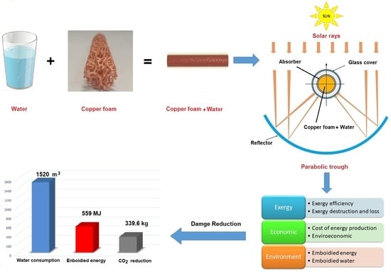
4], etc. A direct absorption parabolic trough collector (DAPTC), as a linear concentrating solar collector, concentrates the solar irradiation in an absorber tube via a reflector, where a heat transfer fluid (HTF) absorbs the thermal energy. The solar radiation is absorbed volumetrically in HTF in a DAPTC. Therefore, they have higher thermal performance [5,6] because of the lower convective losses compared to indirect absorption parabolic trough collectors, of which the sun’s radiation first hits the surface of the absorber tube and then is transferred to the HTF through conduction and convection. Increasing the temperature of the surface of the absorber tube in an indirect absorption parabolic trough collector causes more heat loss to the environment. However, the important challenge in direct absorption collectors is the low radiation absorption coefficient of heat transfer fluids, such as water. To resolve this issue, researchers have proposed various methods such as adding nanoparticles to the base heat transfer fluid [7], utilizing metal porous foams [8], or a combination of metal foam with nanofluids [9] to improve the absorption of radiation and the thermal efficiency of direct absorption solar systems. In general, the use of metal foam in improving the efficiency and heat transfer in indirect and direct absorption solar collectors has been of interest to researchers.
Conducting both experimental and numerical studies, Saedodin et al. [10] evaluated flat-plate solar collector efficiency using metal foam and showed that the thermal efficiency was improved by 18.5%. Jamal-Abad et al. [11] employed copper foam inside a copper absorber tube to inspect the efficiency of a parabolic trough collector (PTC) experimentally. They showed that using foam slightly improved the PTC performance, resulting in an increment in the friction factor. These studies clearly show the effective role of using metal foam to increase heat transfer through the different types of solar collectors. In addition to improving the heat transfer through the HTF flow due to fluid mixing as well as thermal dispersion, applying metal foam in direct absorption solar systems augments the solar absorption. The received rays of the sun enter the pores, and during several collisions with the surface of the pores, the radiant energy is absorbed volumetrically in the porous medium. Then, the working fluid receives the absorbed heat. Therefore, the thermal efficiency of such direct absorption solar systems can improve by utilizing metal foam, although the pressure drop also increases.
The effects of using ceramic foam with single and multiple layers as solar radiation absorbers for heat generation were investigated by Zaversky et al. [12], experimentally and numerically. They revealed that to achieve higher efficiency, the highest possible porosity should be chosen. Furthermore, while the thermal performance depended on the single layer, the second layer had to be applied to satisfy the mechanical stability. Valizade et al. [8] experimentally inspected the effect of employing copper foam on the thermal performance of a DAPTC. Their outcomes revealed that filling the whole absorber tube with the foam (fully porous) could increase the HTF temperature difference to 12.2 °C, which was 270% higher than that without foam, leading to an improvement of thermal efficiency by 171.2%. However, applying metallic foam increased the friction factor substantially. They also illustrated that the maximum thermal efficiency can be achieved by raising the flow rate and declining the HTF inlet temperature.
Heyhat et al. [9] experimentally examined the hydrothermal performance of a DAPTC integrated with semi-porous foam with 95% porosity and 100 mm spacing between pieces of the metal foam and CuO/water nanofluids with different volume fractions. Their results showed that using metal foam significantly augmented the friction factor up to 80 times compared to the pure water. However, it made a maximum temperature difference of 8.8 °C. Moreover, they concluded that combining the metal foam and nanofluid with a volume fraction of 0.1% could improve the thermal efficiency by 79.3%. A similar idea was numerically checked by Esmaeili et al. [13] using copper oxide as the porous foam, as well as nanoparticles. They studied the effects of flow rate, foam pore sizes, layer thicknesses in the channel, and foam positions on the upper and lower sides of the channel. They showed that the maximum thermal efficiency could be achieved once the channel was completely filled with foam. Hooshmand et al. [14] deliberated the effects of applying a combination of nanofluid (SiC/water) and porous foam (SiC ceramic) in a direct absorption solar collector experimentally. The maximum thermal efficiency of the system with porous foam was reported to be equal to 37%. Moreover, they showed that higher porosity and pore size led to higher system thermal performance.
The previously mentioned studies have investigated the use of porous foams from the aspect of energy efficiency. However, consideration of exergy, environmental and economic aspects is also very important for the appraisal of a direct absorption solar energy conversion system. Therefore, some studies have been dedicated to investigating these aspects.
Ehyaei et al. [15] inspected a PTC based on energy, exergy, and economic analysis in Tehran. They applied nanofluids containing CuO and Al2O3 nanoparticles with base fluids of water and thermal oil VP-1. Their numerical outcomes indicated that applying water base fluid resulted in higher exergy and energy efficiencies than thermal oil. Moreover, the addition of nanoparticles to both base fluids generally did not significantly affect the performance of the solar collector.
Moosavian et al. [16] assayed the effects of different climates on the exergy, energy, environmental and economic aspects of a PTC. Their results showed that the highest thermal energy belonged to the Mediterranean Climate, while the Humid Continental Climate had the maximum exergy efficiency.
Mashhadian and Heyhat [17] examined the exergy and energy efficiencies as well as the environmental aspects of a DAPTC in transient behavior mode. They used CuO–water nanofluids as the heat transfer fluid. The results indicated that the thermal efficiency was reduced with the increase in mass flow and inlet temperature of the working fluid.
Jafari et al. [18] explored an optimal location for installing domestic flat-plate solar thermal collectors in Iran based on the energy, economic, and environmental aspects. They applied an analytical hierarchy process and found that Yazd in the center of Iran was the best location to install the solar collector.
Exploring the literature, it turns out that the use of metal foam has been introduced as an effective method to ameliorate the efficiency of the direct absorption solar collectors. However, these studies are very limited, and thus far, no study has been reported on the exergy, environmental and economic analysis of different schemes of a metal foam insertion into the absorber tube of a DAPTC. Therefore, this paper aims to analyze a DAPTC filled with various arrangements of metal porous foams based on exergy, environmental and economic aspects. In this regard, the experimental data were collected for various flow rates and inlet temperatures of HTF at ten distinct schemes of porous metal foams. The exergy efficiency, entropy generation ratio, embodied water, embodied energy, Bejan number, and levelized cost of energy (LCE) were obtained and compared for different placements of porous foams as volumetric absorbers of the DAPTC.
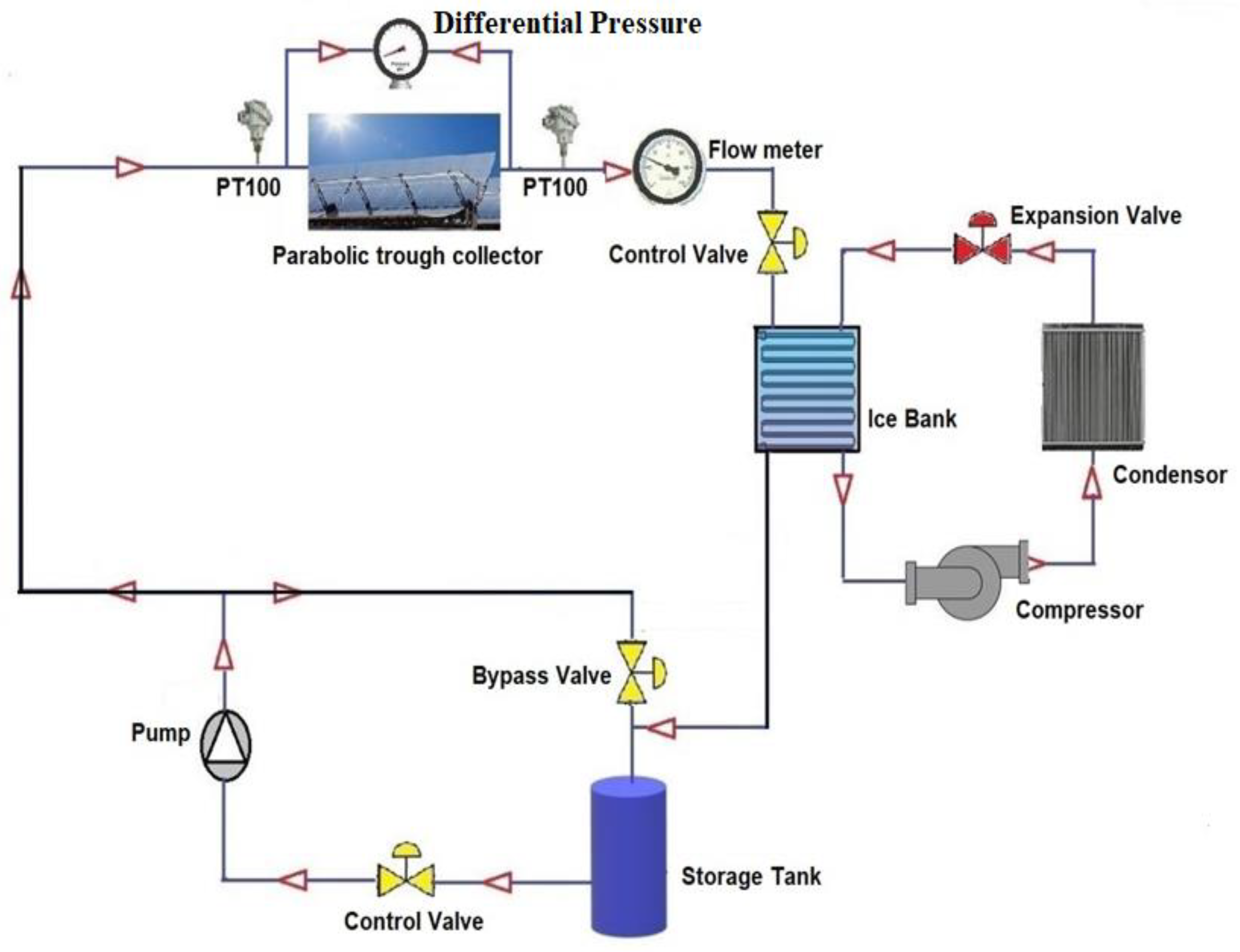
In Section 2, the experimental setup is described. Measurement instruments, specifications and patterns of the applied metal foams, and uncertainty analysis are given in this section. The exergy analysis method and pumping power calculation are presented in Section 3 and Section 4, respectively. Then, in Section 5, the results are reported and discussed. In this section, the results of exergy analysis, pumping power, analysis of environmental effects in the form of embodied water and embodied energy, and economic analysis are explained. Finally, in Section 6, the results are summarized.

2. Experimental Setup

The setup comprised a parabolic reflector, a glass receiver absorber tube filled with metal foam and a glass cover to reduce heat loss, and several instruments for measuring the operating conditions. To raise the stability of the system and keep its weight low, a wooden structure (medium-density fiberboard) was used for the frame of the DAPTC. The geometrical and optical specifications of the different system components are provided in Table 1. For the receiver cover and tube, Pyrex glass was selected to use due to its good optical properties, such as low absorption coefficient and high transmissivity.
To define the reflector parabolic, the following equation was used [8]:
Y = 1.14 x 2
More details of the experimental setup are given in [8,9].

2.1. Working Cycle, Measurement Instruments, and Uncertainty Analysis

A schematic diagram of the working cycle of the DAPTC with the cooling system is demonstrated in Figure 1. An ice bank as a cooling system is employed to remove the absorbed heat of HTF to control its inlet temperature in the range of 20–40 °C. Moreover, a Grundfos UPS2 pump is utilized for circulating the HTF through the absorber tube. The flow of HTF is regulated by several control valves. Table 2 represents the details of the measurement instruments and their accuracy. To ensure that the presented experimental outcomes are accurate and reliable, all the experiments are conducted three times, and uncertainty analysis is performed. The accuracy of the instruments can be found from the information provided by the manufacturer. Then, using the following equation, the total uncertainty error of the experiments is calculated as 2.95% [19].
T o t a l   U n c e r t a i n t y = U n c e r t a i n t y   o f   d e v i c e s   2  

2.2. Specifications and Patterns of the Metal Foams

Porous foams can enhance the DAPTC performance by mixing the HTF, increasing the heat transfer surface, thermal dispersion, and improving the volumetric absorption of solar radiation. However, they increase the friction factor, pressure drop, and pumping power [20]. Hence, porous media with different arrangements and schemes are employed inside the receiver tube to compare their preference. To this end, ten different layouts along with the base case, i.e., without porous, are designed as described in Table 3. The porous foam is made of copper due to its high thermal conductivity and volumetric effect [21]. Each piece is a cylinder with a length of 100 mm, diameter of 22 mm, porosity of 95%, and a pore diameter of 10 PPI. Thus, to completely fill the absorber tube with metal foam, i.e., fully porous, fourteen pieces of them are utilized. For the cases filled partially with foam, i.e., semi-porous, seven pieces are used with 100 mm spacing. For the cases with a hollow circle, the inner and outer diameters are 14 and 22 mm, respectively. Furthermore, the diameter of solid cylinders with a smaller diameter is 14 mm.

3. Exergy Analysis

Different parameters including thermal efficiency, pumping power, entropy generation, and exergy are deliberated to compare the applying the various layouts of copper foams. The thermal efficiency of the DAPTC can be calculated as follows [22]:
η th =   m ˙ C p T out T in IA c , aperture
where m ˙ (kg/s), C p (J/kg·°C), T out (°C), and T in (°C) are HTF mass flow rate, specific heat capacity, outlet, and inlet temperatures, respectively. Moreover, I (W/m2) and A c , aperture (m2) refer to the solar irradiation and collector aperture area. The exergy balance for the DAPTC is as follows [23]:
E ˙ x sun +   E ˙ x in   =   E ˙ x out   +   E ˙ x loss   +   E ˙ x d
In this equation, E ˙ x sun is the solar irradiation exergy received by the system, which can be defined by the following equation [23]:
E ˙ x sun   =   IA c ,   aperture   1 4 3 T amb T sun   +   1 3 T amb T sun 4
Herein, Tamb and Tsun represent the ambient and sun (≈5800 K) temperatures, respectively. The difference between output and input exergies is useful exergy, which can be calculated by [24]:
E ˙ x useful   =   E ˙ x out   E ˙ x in   =   m ˙ C p T out T in   m ˙ C p T amb ln T out T in   m ˙ T amb Δ P ρ T m
Tm is the average of the HTF inlet and outlet temperatures. The exergy efficiency of the DAPTC can be determined as follows:
η Ex   =   E ˙ x useful E ˙ x sun
To evaluate the entropy generation through the system, the losses ( m ˙ x loss ) due to both thermal and frictional generation should be taken into account. The entropy generation owing to the HTF friction can be calculated as follows [25,26]:
S ˙ g , friction =   S ˙ Δ P ρ T m
S ˙ g , thermal =   m ˙ C p T out T in   m ˙ C p T amb ln T out T in T amb
Eventually, the total entropy generation can be calculated as follows [26,27]:
S ˙ g , total =   S ˙ g , friction +   S ˙ g , thermal
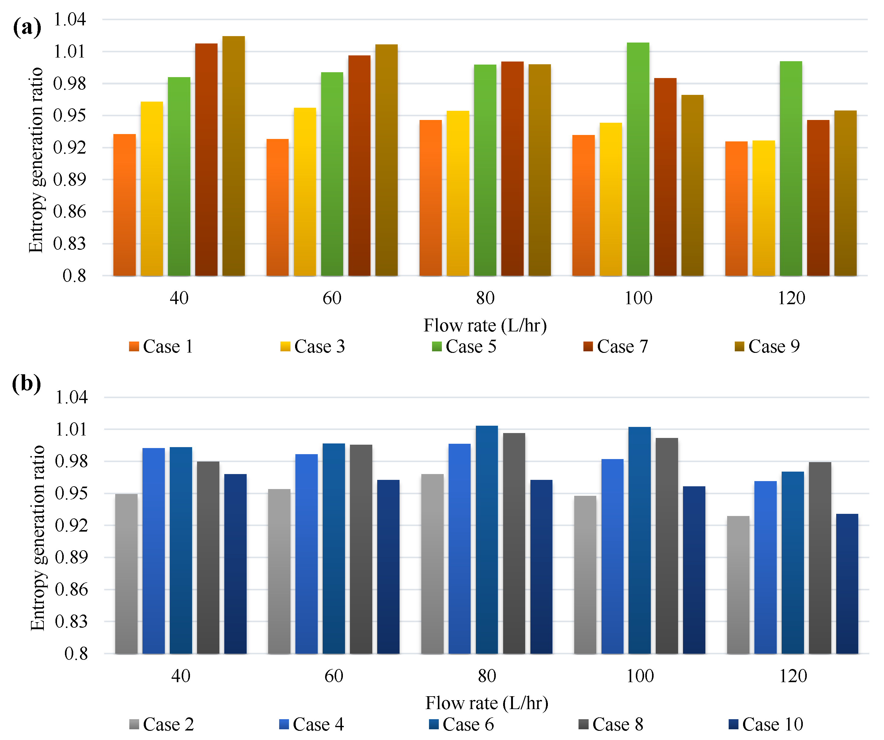
To better evaluate the metal foam insertion on the entropy generation, the entropy generation ratio as the ratio of the entropy generation of a system with metal foams to the entropy generation of the base case is defined [28]:
Entropy   generation   ratio =   S ˙ g , total   for   metal   case S ˙ g , total   for   base   case
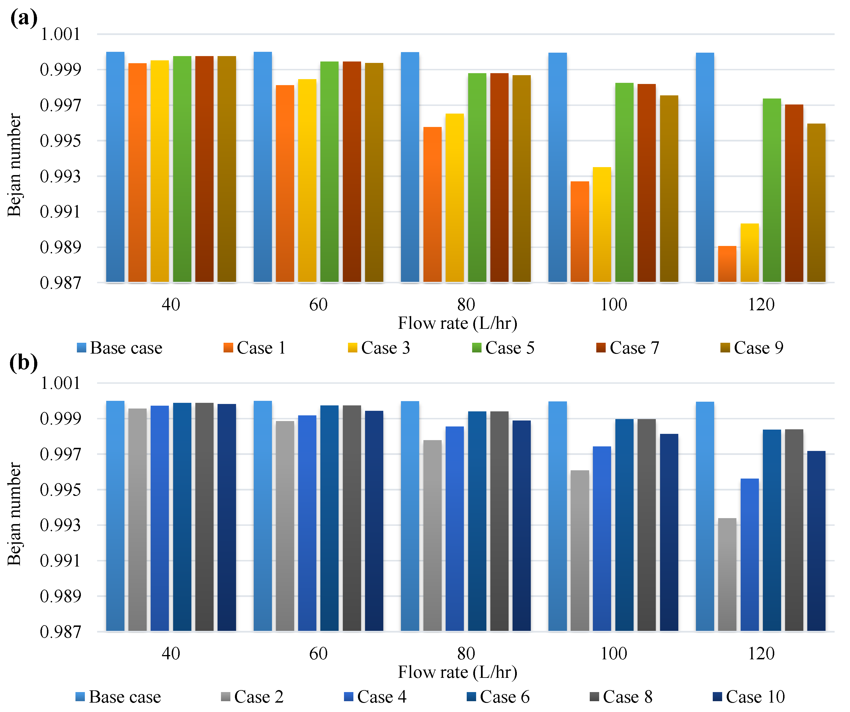
Moreover, to consider the contribution of the pressure drop and heat transfer in the total entropy generation, the Bejan number (Be) is used [28], as follows:
Be = S ˙ g , thermal S ˙ g , total

4. Friction Factor and Pumping Power

Using the measured pressure drop through the receiver tube ( Δ P ), the friction factor can be determined by:
f = Δ P l d ρ U 2 2
where U, l, ρ and d are the average velocity of HTF, length of pipe, HTF density, and diameter of the receiver glass, respectively. Using porous foam as the volumetric absorber increases the pressure loss, leading to a rise in pumping power. The amount of pumping power can be calculated by [29]:
W pump = Δ P   m ˙ ρ

5. Results and Discussion

The effects of using foams with different configurations on the performance of the DAPTC (according to the ASHRAE 93-2010 standard) are evaluated under three different inlet temperatures of 20, 30, and 40 °C and various HTF flow rates in the range of 40–120 L/h (liter/hour). The performance of the DAPTC was verified in previous works [8,9].

5.1. Exergy Analysis

The second law of thermodynamics is employed to assess the system from the quality of energy and irreversibility viewpoints. Figure 2 demonstrates the ratio of the useful exergy ( E ˙ x useful ) of the system filled with metal foam for considered cases to the base case with pure water for different flow rates at an inlet temperature of 20 °C. Using metal foam results in a higher useful exergy in all cases. However, the maximum values almost take place for 120 L/h. The maximum useful exergy ratio belongs to Case 1 in all flow rates. The exergy efficiency of the best cases, including Case 1, Case 2, Case 9, and Case 10, are presented in Figure 3. The exergy efficiency of the collector for the base case, Case 1, Case 2, Case 9, and Case 10 are about 7.9%, 14.2%, 12%, 12.3%, and 11.8%, respectively. Increasing the flow rate to 120 L/h increases these amounts to nearly 10.6%, 20.4%, 17.7%, 18.9%, and 17.7% for base case, Case 1, Case 2, Case 9, and Case 10, respectively. The increment of exergy efficiency by raising the flow rate can be related to the increase in the useful exergy by enhancing the heat absorption.
The amount of entropy generation is calculated to account for the irreversibilities of the system. The entropy generation ratio is depicted in Figure 4. The outcomes show that applying metal foam may increase or decrease the entropy generation through the system, depending on the flow rate and foam arrangement. Using foams has two opposite effects on the exergy: (1) increasing the share of thermal exergy by growing the useful absorbed radiation heat, and (2) increasing the destroyed exergy because of the increased pressure drop. Therefore, for some cases such as Case 1, 2, and 3 due to their significant enhancement on the thermal energy, the first effect overcomes the second one, and as a result, the entropy generation ratio is less than one, while in other cases it can be different according to the mass flow rate. For example, at a flow rate of 80 L/h, six cases have an entropy generation ratio of around 1, while increasing and decreasing the flow rate to 120 and 40 L/h, respectively, reduces the number of these cases to one and two. Using Case 1 reflects the best entropy generation ratio in all flow rates.
To consider the effect of the pressure drop, the Bejan number is calculated and is presented in Figure 5. Maximizing the Bejan number (Be ≈ 1) means reducing the irreversibilities due to the pressure drop. Increasing the flow rate reduces the Bejan number due to the increment in pressure drop and an increase in frictional entropy generation contribution. The fully porous tube, i.e., Case 1, has the lower Bejan number. Based on the results, although the difference between the considered cases is negligible at a low flow rate, increasing the flow rate raises the difference, where the worst cases are Case 1 and Case 3, respectively. This reduction leads to an escalation of the pumping power, which is discussed in the next section.

5.2. Pressure Drop and Pumping Power

Using foam inside the tube dramatically increases the pressure drop Figure 6 compares the results of the base case and Case 2 with the same outcomes of Reference [9] to ensure the accuracy and consistency between the results.
The minimum (for the flow rate of 40 L/h) and maximum (for the flow rate of 120 L/h) required pumping powers for all representative cases are shown in Figure 7. According to Figure 7a, for 40 L/h, the highest required pumping power belongs to Case 1, Case 3, and Case 2. The results show that using partially porous foam can noticeably reduce the required pumping power compared to the full porous. The required pumping powers for Case 1, Case 3, and Case 2 are about 153.4, 106, and 92.8 times higher than the base case (pure water) for 120 L/h, respectively.

5.3. Environmental Analysis

Ameliorating the thermal performance of the solar collector makes it possible to use it in smaller sizes. The size reduction of the aperture area of the solar collector can be obtained by considering the thermal efficiency of each case (ηth) for generating similar thermal energy as follows [30]:
A c , aperture =   m ˙ C p T out T in I η th
Comparing the obtained A c , aperture from Equation (15) with that of the base case, the size reduction can be determined for each case. The results are listed in Table 4 for an inlet temperature of 20 °C at different flow rates. The use of metal foam in all arrangements leads to the improvement of the thermal efficiency of collector. Thus, there is a reduction in the DAPTC size at the same energy produced by the system with the pure tube. As can be seen, the size reduction for different cases is up to 50%. The maximum size reduction is for Case 1 at the highest flow rate of 120 L/h (bold underlined number in the table). The size reduction for Case 5, Case 6, and Case 8 in all flow rates is lower than 20%, while for Case 1, it is higher than 40%. As a result, except in some limited cases, using metal foam can noticeably reduce the size of the system. Because the optimum size reduction in most cases occurs at a flow rate of 120 L/h, only this flow rate is considered for the rest of the study.
Using the size reduction for each case, the embodied energy, water consumption, and their corresponding percentage decrease in water and energy usage of the DAPTC are evaluated as demonstrated in Table 5. Only the employed energy for manufacturing of the system is considered, which is responsible for about 70% of the total energy [31]. Moreover, the foam share in total cost is negligible compared to the other part. Therefore, its effect is neglected. Two main materials for manufacturing a DAPTC are glass and steel [32] with a weight ratio of 1 to 3, e.g., for a DAPTC with 40 kg weight, the weight of used glass and steel material will be 10 and 30 kg, respectively. Moreover, the embodied energy for glass and steel are 15.9 and 32 MJ/kg, respectively, and the water indexes are 98.64 m3/kg and 8.24 m3/kg [33,34]. Finally, using these values and size reduction, according to Table 5, the best embodied water and energy usage belongs to Case 1.
The amounts of reduction in pollutants, including nitrogen oxides (NOx), carbon dioxide (CO2), and sulfur oxides (SOx), by reducing the embodied energy are discussed here. According to the International Energy Agency (IEA), the different sources of electricity generation and their shares in producing the mentioned pollutants are listed in Table 6 [35]. As can be seen, coal is the primary energy source used for electricity production by 38%, and it ranks first as responsible for polluting the environment. Using these data and the calculated embodied energy in Table 5, the amounts of reduction in CO2, NOx, and SOx are calculate, and they are presented in Table 7. The results show a noticeable reduction in CO2 by using metal foam in DAPTC. For example, the reduction of CO2 is 339.62, 304.30, and 276.45 kg, for Case 1, Case 9, and Case 2, respectively. Moreover, using metal foam could slightly reduce the NOx and SOx. Consequently, applying metal foam to absorb the solar radiation volumetrically can reduce manufacturing costs and generate pollutants to achieve a specific thermal efficiency.

5.4. Economic Analysis

In this section, to conduct the economic evaluation of the DAPTC integrated with metal foam, the Levelized Cost of Energy (LCE) is utilized as follows [36]:
LCE = CRF × C invest + C O & M m ˙ C p T out T in × t hw
Herein, Cinvest, CO&M, and thw are the investments cost, operation and maintenance costs (assumed 2.5% of the Cinvest), and hours of working, respectively. The main parts of the DAPTC, including the storage tank, solar collector (reflector and receiver), and HTF have capital costs of 27, 148, and 4 USD/m2, respectively [23]. Moreover, the price of copper metal foam is about 770 USD/m3 [37]. The capital recovery factor (CRF) can be calculated based on the system lifetime (n) and interest rate (i) as follows [36]:
CRF = i × i + 1 n i + 1 n 1
In the present study, the system lifetime is considered as 20 years, and the interest rate is 6%. Figure 8 demonstrates the variations of the LCE with flow rates at the inlet temperature of 20 °C for different porous arrangements. According to Equation (16), the LCE has a reverse relationship with thermal power. To clear the calculation of LCE, the values of all parameters in Equation (16) are summarized in Table 8.
Therefore, any improvement in generated heat can reduce energy production costs. Two effective parameters are investigated, including the mass flow rate and metal foam inserted in the absorber tube. First, considering the base case, increasing the mass flow rate due to the improvement in thermal power leads to a reduction in LCE. Moreover, due to enhancing the thermal power by metal foam insertion into the tube, except for in Case 8 at a mass flow rate of 40 L/h, using metal foam declines the LCE. This reduction is more pronounced at larger mass flow rates for cases with higher volume porous inserts. For example, considering the highest amount of mass flow rate, for the cost of heat production using Case 1 and Case 2, the LCE reduces by 49.85% and 40.65%, respectively.

6. Conclusions

Exergy, economic and environmental analysis of a direct absorption parabolic trough collector filled with various configurations of porous metal foam were investigated. Different parameters, including exergy efficiency, entropy generation, Bejan number, and pumping power at various HTF flow rates (40–120 L/h) and inlet temperatures (20–40 °C) were evaluated. Moreover, different configurations were compared from environmental, size reduction, and economic viewpoints. The key findings are summarized as follows:
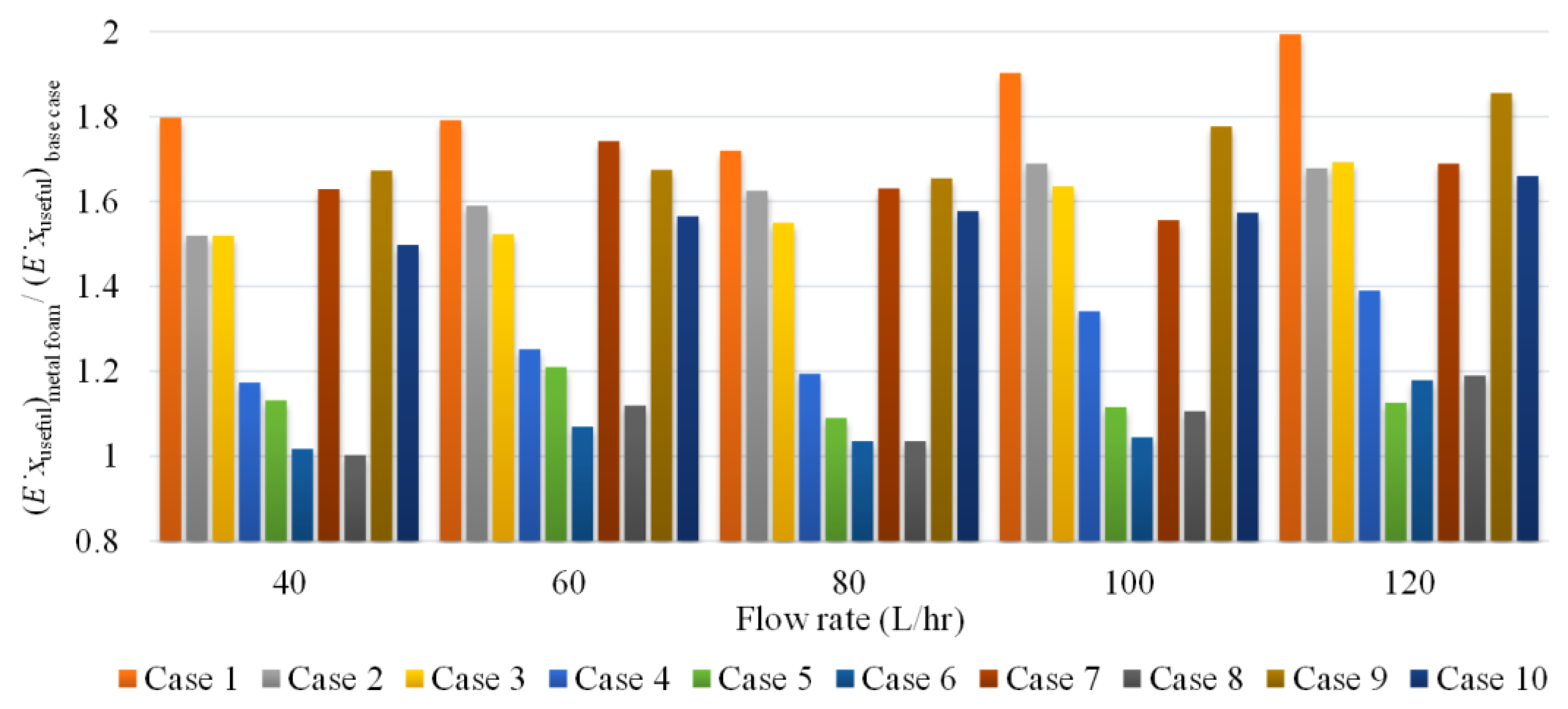
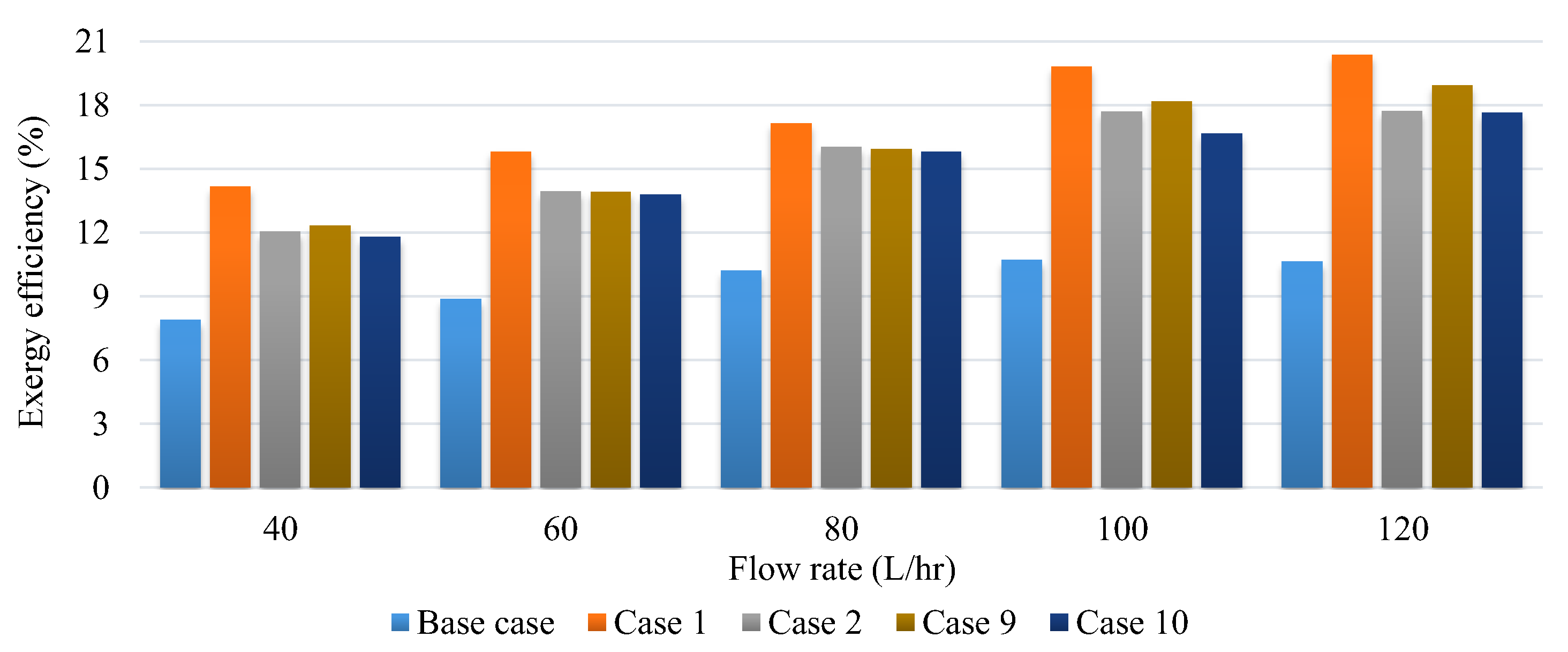
  • Based on the exergy analysis, the maximum useful exergy ratio is provided by Case 1 in all flow rates, where the exergy efficiency reached a high value of 20.4% at 120 L/h.
  • Using metal foam resulted in either increasing or decreasing entropy generation, depending on flow rate and foam arrangement. Furthermore, the Bejan number is reduced at higher flow rates and larger porous configurations due to the higher pressure drop and frictional entropy generation. The worst case regarding the Bejan number was Case 1, leading to a significant rise in pumping power.
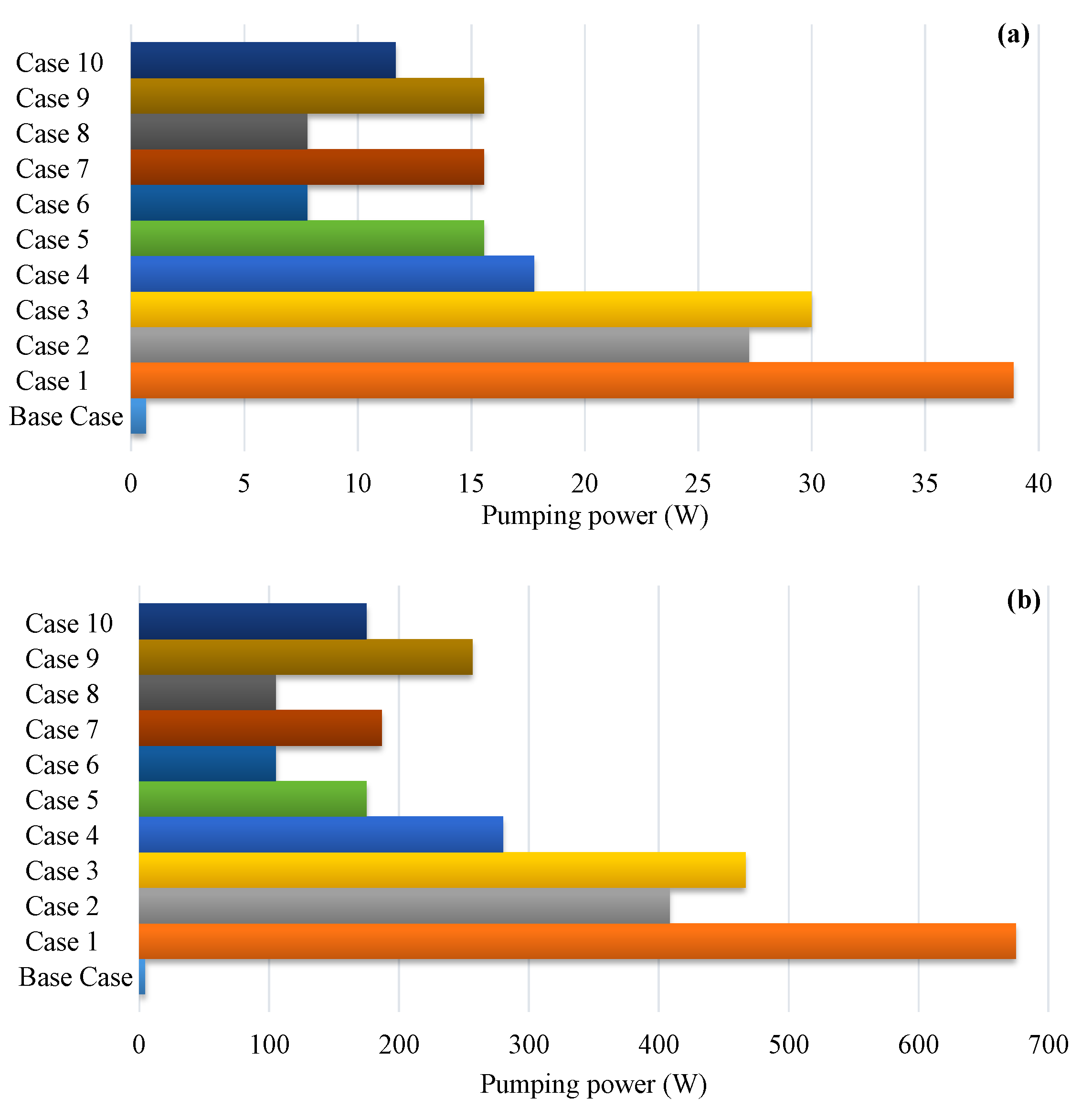
  • In terms of the pressure drop, using foam dramatically increased the pumping power. The required pumping powers for Case 1 and Case 2 were about 153.4 and 92.8 times higher than the base case, i.e., pure water, respectively.
  • The environmental and size reduction analyses demonstrated that using Case 1 has a maximum size reduction of 50%, embodied energy of 559.5 MJ, reduction in water consumption of 1520.8 kL, and reduction in CO2 by 339.62 kg compared to the base case.
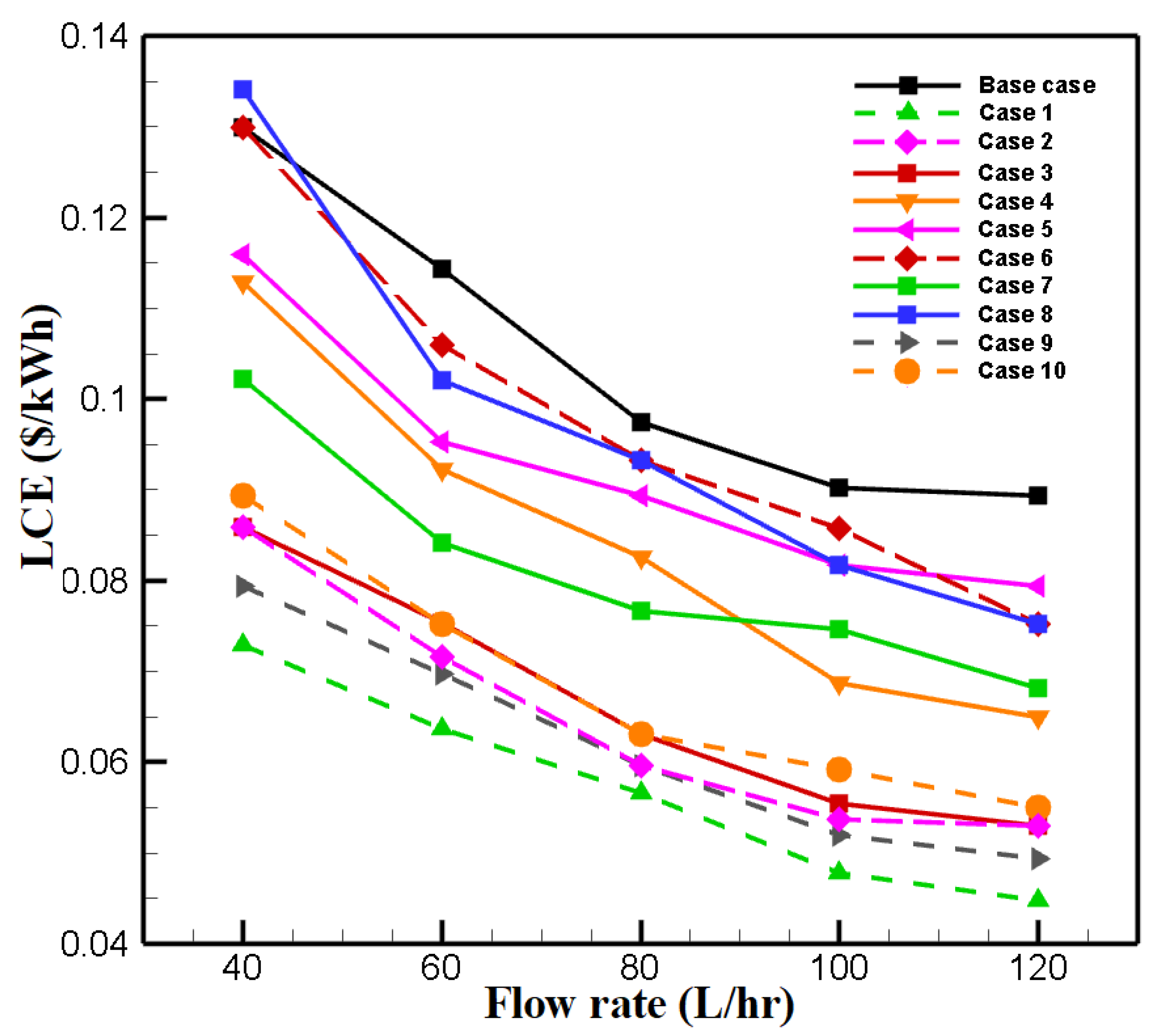
  • Investigating the LCE showed that increasing the mass flow rate and adding metal foam reduced the heat production cost, e.g., Case 1 at highest mass flow rate is 50% lower than the base case.
Consequently, although employing porous foam in the form of Case 1 reflected the best performance in terms of exergy, economic and environmental aspects, the required pumping power for this case showed a huge difference from other cases. Therefore, the designer should consider all these positive and negative effects simultaneously.

Author Contributions

Conceptualization, M.M.H.; Data curation, M.Z.K.; Formal analysis, M.Z.K.; Methodology, M.M.H. and M.Z.K.; Resources, M.Z.K.; Supervision, M.M.H.; Validation, M.Z.K.; Writing—original draft, M.Z.K.; Writing—review and editing, M.M.H. All authors have read and agreed to the published version of the manuscript.

Funding

This research received no external funding.

Data Availability Statement

The data presented in this study are available in this article.

Conflicts of Interest

The authors declare no conflict of interest.

Nomenclature

Aarea (m2)
Cpspecific heat (J/kg.K)
C invest investments cost (USD)
C O & M operation and maintenance costs (USD)
ddiameter of receiver tube (m)
E ˙ exergy (W)
ffriction factor
Isolar irradiation (W/m2)
llength of receiver tube (m)
m ˙ mass flow rate (kg/s)
ΔPdifferential pressure (Pa)
S ˙ entropy generation (J/K)
Ttemperature (K)
ttime (s)
t hw hours of working (h/day)
Uaverage velocity (m/s)
Wpumppumping power (W)
Greek Letters
ρdensity (kg/m3)
ηefficiency (%)
Subscripts
ambambient temperature
ccollector
ggeneration
ininlet
outoutlet
ththermal
sunsolar
Abbreviations
BeBejan number
CRFcapital recovery factor
DAPTCdirect adsorption parabolic trough collector
HTFheat transfer fluid
LCElevelized cost of energy (USD/kWh)
PTCparabolic trough collectors

References

  1. Ramachandran, T.; Mourad, A.H.I.; Hamed, F. A Review on Solar Energy Utilization and Projects: Development in and around the UAE. Energies 2022, 15, 3754. [Google Scholar] [CrossRef]
  2. Suman, S.; Khan, M.K.; Pathak, M. Performance enhancement of solar collectors—A review. Renew. Sustain. Energy Rev. 2015, 49, 192–210. [Google Scholar] [CrossRef] [Green Version]
  3. Alimi, O.A.; Meyer, E.L.; Olayiwola, O.I. Solar Photovoltaic Modules’ Performance Reliability and Degradation Analysis—A Review. Energies 2022, 15, 5964. [Google Scholar] [CrossRef]
  4. Maadi, S.R.; Khatibi, M.; Ebrahimnia-Bajestan, E.; Wood, D. Coupled thermal-optical numerical modeling of PV/T module—Combining CFD approach and two-band radiation DO model. Energy Convers. Manag. 2019, 198, 111781. [Google Scholar] [CrossRef]
  5. Raj, P.; Subudhi, S. A review of studies using nanofluids in flat-plate and direct absorption solar collectors. Renew. Sustain. Energy Rev. 2018, 84, 54–74. [Google Scholar] [CrossRef]
  6. Xu, G.; Chen, W.; Deng, S.; Zhang, X.; Zhao, S. Performance evaluation of a nanofluid-based direct absorption solar collector with parabolic trough concentrator. Nanomaterials 2015, 5, 2131–2147. [Google Scholar] [CrossRef] [Green Version]
  7. Kasaeian, A.; Daneshazarian, R.; Rezaei, R.; Pourfayaz, F.; Kasaeian, G. Experimental investigation on the thermal behavior of nanofluid direct absorption in a trough collector. J. Clean. Prod. 2017, 158, 276–284. [Google Scholar] [CrossRef]
  8. Valizade, M.; Heyhat, M.M.; Maerefat, M. Experimental study of the thermal behavior of direct absorption parabolic trough collector by applying copper metal foam as volumetric solar absorption. Renew. Energy 2020, 145, 261–269. [Google Scholar] [CrossRef]
  9. Heyhat, M.M.; Valizade, M.; Abdolahzade, S.; Maerefat, M. Thermal efficiency enhancement of direct absorption parabolic trough solar collector (DAPTSC) by using nanofluid and metal foam. Energy 2020, 192, 116662. [Google Scholar] [CrossRef]
  10. Saedodin, S.; Zamzamian, S.; Nimvari, M.E.; Wongwises, S.; Jouybari, H.J. Performance evaluation of a flat-plate solar collector filled with porous metal foam: Experimental and numerical analysis. Energy Convers. Manag. 2017, 153, 278–287. [Google Scholar] [CrossRef]
  11. Jamal-Abad, M.T.; Saedodin, S.; Aminy, M. Experimental investigation on a solar parabolic trough collector for absorber tube filled with porous media. Renew. Energy 2017, 107, 156–163. [Google Scholar] [CrossRef]
  12. Zaversky, F.; Aldaz, L.; Sánchez, M.; Ávila-Marín, A.L.; Roldán, M.I.; Fernández-Reche, J.; Füssel, A.; Beckert, W.; Adler, J. Numerical and experimental evaluation and optimization of ceramic foam as solar absorber–Single-layer vs multi-layer configurations. Appl. Energy 2018, 210, 351–375. [Google Scholar] [CrossRef]
  13. Esmaeili, M.; Karami, M.; Delfani, S. Performance enhancement of a direct absorption solar collector using copper oxide porous foam and nanofluid. Int. J. Energy Res. 2020, 44, 5527–5544. [Google Scholar] [CrossRef]
  14. Hooshmand, A.; Zahmatkesh, I.; Karami, M.; Delfani, S. Porous foams and nanofluids for thermal performance improvement of a direct absorption solar collector: An experimental study. Environ. Prog. Sustain. Energy 2021, 40, e13684. [Google Scholar] [CrossRef]
  15. Ehyaei, M.A.; Ahmadi, A.; Assad, M.E.; Hachicha, A.A.; Said, Z. Energy, exergy and economic analyses for the selection of working fluid and metal oxide nanofluids in a parabolic trough collector. Sol. Energy 2019, 187, 175–184. [Google Scholar] [CrossRef]
  16. Moosavian, S.F.; Borzuei, D.; Ahmadi, A. Energy, exergy, environmental and economic analysis of the parabolic solar collector with life cycle assessment for different climate conditions. Renew. Energy 2021, 165, 301–320. [Google Scholar] [CrossRef]
  17. Mashhadian, A.; Heyhat, M.M. Energy, exergy, and environmental assessments of a direct absorption parabolic trough collector based on nanofluid volume absorption approach. Energy Sources Part A Recovery Util. Environ. Eff. 2022, 44, 4230–4255. [Google Scholar] [CrossRef]
  18. Jafari, S.; Sohani, A.; Hoseinzadeh, S.; Pourfayaz, F. The 3E Optimal Location Assessment of Flat-Plate Solar Collectors for Domestic Applications in Iran. Energies 2022, 15, 3589. [Google Scholar] [CrossRef]
  19. Praveenkumar, S.; Gulakhmadov, A.; Agyekum, E.B.; Alwan, N.T.; Velkin, V.I.; Sharipov, P.; Safaraliev, M.; Chen, X. Experimental Study on Performance Enhancement of a Photovoltaic Module Incorporated with CPU Heat Pipe—A 5E Analysis. Sensors 2022, 22, 6367. [Google Scholar] [CrossRef]
  20. Akar, S.; Rashidi, S.; Esfahani, J.A. Appropriate position of porous insert in a heat exchanger by thermohydraulic analysis. Heat Transf.—Asian Res. 2017, 46, 1363–1379. [Google Scholar] [CrossRef]
  21. Valizade, M.; Heyhat, M.; Maerefat, M. Experimental comparison of optical properties of nanofluid and metal foam for using in direct absorption solar collectors. Sol. Energy Mater. Sol. Cells 2019, 195, 71–80. [Google Scholar] [CrossRef]
  22. Tukenmez, N.; Koc, M.; Ozturk, M. Development and performance analysis of a concentrating collector combined plant for multigeneration purposes. Energy Convers. Manag. 2020, 205, 112415. [Google Scholar] [CrossRef]
  23. Saray, J.A.; Heyhat, M.M. Modeling of a direct absorption parabolic trough collector based on using nanofluid: 4E assessment and water-energy nexus analysis. Energy 2022, 244, 123170. [Google Scholar] [CrossRef]
  24. Vahidinia, F.; Khorasanizadeh, H.; Aghaei, A. Comparative energy, exergy and CO2 emission evaluations of a LS-2 parabolic trough solar collector using Al2O3/SiO2-Syltherm 800 hybrid nanofluid. Energy Convers. Manag. 2021, 245, 114596. [Google Scholar] [CrossRef]
  25. Sardarabadi, M.; Hosseinzadeh, M.; Kazemian, A.; Passandideh-Fard, M. Experimental investigation of the effects of using metal-oxides/water nanofluids on a photovoltaic thermal system (PVT) from energy and exergy viewpoints. Energy 2017, 138, 682–695. [Google Scholar] [CrossRef]
  26. Mahian, O.; Kianifar, A.; Sahin, A.Z.; Wongwises, S. Entropy generation during Al2O 3/water nanofluid flow in a solar collector: Effects of tube roughness, nanoparticle size, and different thermophysical models. Int. J. Heat Mass Transf. 2014, 78, 64–75. [Google Scholar] [CrossRef]
  27. Kazemian, A.; Yaser, B.; Khatibi, M.; Ma, T. Performance prediction and optimization of a photovoltaic thermal system integrated with phase change material using response surface method. J. Clean. Prod. 2021, 290, 125748. [Google Scholar] [CrossRef]
  28. Bellos, E.; Tzivanidis, C.; Tsimpoukis, D. Enhancing the performance of parabolic trough collectors using nanofluids and turbulators. Renew. Sustain. Energy Rev. 2018, 91, 358–375. [Google Scholar] [CrossRef]
  29. Maadi, S.R.; Khatibi, M.; Ebrahimnia-Bajestan, E.; Wood, D. A parametric study of a novel PV/T system model which includes the greenhouse effect. In Proceedings of the IEA SHC International Conference on Solar Heating and Cooling for Buildings and Industry 2019, Santiago, Chile, 4–7 November 2019. [Google Scholar]
  30. Faizal, M.; Saidur, R.; Mekhilef, S.; Alim, M.A. Energy, economic and environmental analysis of metal oxides nanofluid for flat-plate solar collector. Energy Convers. Manag. 2013, 76, 162–168. [Google Scholar] [CrossRef]
  31. Mashhadian, A.; Heyhat, M.M.; Mahian, O. Improving environmental performance of a direct absorption parabolic trough collector by using hybrid nanofluids. Energy Convers. Manag. 2021, 244, 114450. [Google Scholar] [CrossRef]
  32. Otanicar, T.P.; Phelan, P.E.; Prasher, R.S.; Rosengarten, G.; Taylor, R.A. Nanofluid-based direct absorption solar collector. J. Renew. Sustain. Energy 2010, 2, 033102. [Google Scholar] [CrossRef] [Green Version]
  33. Praseeda, K.; Reddy, B.V.; Mani, M. Life-Cycle Energy Assessment in Buildings: Framework, Approaches, and Case Studies; Elsevier: Amsterdam, The Netherlands, 2017. [Google Scholar]
  34. Treloar, G.J.; Crawford, R.H. Database of Embodied Energy and Water Values for Materials; University of Melbourne: Melbourne, Australia, 2010. [Google Scholar]
  35. IEA. Electricity Information: Overview; IEA: Paris, France, 2020.
  36. Boukelia, T.; Arslan, O.; Mecibah, M. ANN-based optimization of a parabolic trough solar thermal power plant. Appl. Therm. Eng. 2016, 107, 1210–1218. [Google Scholar] [CrossRef]
  37. Yang, X.; Feng, S.; Zhang, Q.; Chai, Y.; Jin, L.; Lu, T.J. The role of porous metal foam on the unidirectional solidification of saturating fluid for cold storage. Appl. Energy 2017, 194, 508–521. [Google Scholar] [CrossRef]
Figure 1. Schematic diagram of direct absorption parabolic trough collector working cycle.
Energies 15 08150 g001
Figure 2. The ratio of the useful exergy of metal foam cases to the base case for different flow rates at the inlet temperature of 20 °C.
Energies 15 08150 g002
Figure 3. The exergy efficiency of Case 1, Case 2, Case 9, and Case 10 for different flow rates at the inlet temperature of 20 °C.
Energies 15 08150 g003
Figure 4. Entropy generation ratio of (a) fully porous and (b) semi-porous cases at different flow rates for the inlet temperature of 20 °C.
Energies 15 08150 g004
Figure 5. Bejan number at different flow rates for the inlet temperature of 20 °C for (a) fully porous cases and (b) semi-porous cases.
Energies 15 08150 g005
Figure 6. Comparison between the results of this study and results presented by Heyhat et al. [9].
Energies 15 08150 g006
Figure 7. Pumping power for considered cases at the inlet temperature of 20 °C for flow rates of (a) 40 and (b) 120 L/h.
Energies 15 08150 g007
Figure 8. Variations of the LCE with flow rates at the inlet temperature of 20 °C.
Energies 15 08150 g008
Table 1. The geometrical and optical specifications of the DAPTC.
ParameterValueUnit
Aperture width0.7m
Parabola length1.5m
Concentrator aperture area0.98m2
Focal length0.175m
Rim angle90degree
Reflector materialsteel mirror-
Reflector thickness1mm
Reflector reflectivity0.93-
Receiver length1.4m
Outer diameter of receiver glass26mm
Thickness of receiver glass2mm
Outer diameter of cover glass60mm
Thickness of cover glass5mm
Receiver transmittance0.95-
Glass cover transmittance0.95-
Table 2. The list of equipment for measurement and their accuracy.
EquipmentMeasurementAccuracy (%)Uncertainty (%)
TES-1333R solar power meterSolar irradiation ± 52.888
PT100 thermocoupleInlet and outlet temperatures ± 0.10.058
Bulb thermometerAmbient temperature ± 10.577
Differential pressure transmitterPressure drop in the tube ± 0.0650.038
Volumetric flow meter (Zenner international GmbH & Co. KG)Fluid flow rate ± 0.010.006
Table 3. Different considered layouts of the metal foam inside the DAPTC.
Case No.Cross-Sectional View of the Tube Filled with FoamLongitudinal View of the Tube Filled with Foam
Base caseEnergies 15 08150 i001Energies 15 08150 i002
1Energies 15 08150 i003Energies 15 08150 i004
2Energies 15 08150 i005Energies 15 08150 i006
3Energies 15 08150 i007Energies 15 08150 i008
4Energies 15 08150 i009Energies 15 08150 i010
5Energies 15 08150 i011Energies 15 08150 i012
6Energies 15 08150 i013Energies 15 08150 i014
7Energies 15 08150 i015Energies 15 08150 i016
8Energies 15 08150 i017Energies 15 08150 i018
9Energies 15 08150 i019Energies 15 08150 i020
10Energies 15 08150 i021Energies 15 08150 i022
Table 4. Size reduction by using metal foam at different flow rates.
CaseFlow Rate (L/h)
406080100120
Case 144.1%44.4%42.1%47.2%50.0% *
Case 234.0%37.5%38.9%40.6%40.7%
Case 334.0%34.2%35.3%38.7%40.7%
Case 413.2%19.4%15.4%24.0%27.3%
Case 510.8%16.7%8.3%9.5%11.1%
Case 60.0%7.4%4.3%5.0%15.8%
Case 721.4%26.5%21.4%17.4%23.8%
Case 80%10.7%4.3%9.5%15.8%
Case 938.9%39.0%38.9%42.4%44.8%
Case 1031.3%34.2%35.3%34.5%38.5%
* The maximum size reduction.
Table 5. Embodied energy, water usage, and corresponding saving for different metal foam configurations at the flow rate of 120 L/h.
CaseEmbodied Energy (MJ)Water Consumption (kL)Energy and Water Saving (%)
Base case11193041.6-
Case 1559.51520.850.0
Case 2663.61803.740.7
Case 3663.61803.740.7
Case 4813.52211.227.3
Case 5994.82704.011.1
Case 6942.22561.015.8
Case 7852.72317.723.8
Case 8942.22561.015.8
Case 9617.71679.044.8
Case 10688.21870.638.5
Table 6. Share of different sources in generating electricity and their emission based on the IEA report [35].
FuelShare of Fuel (%)NOx (kg/MJ)SOx (kg/MJ)CO2 (kg/MJ)
Coal380.000310.00050.274
Natural gas2300.000030.113
Renewable energy19.9000
Hydro16.2000
Oil2.9000.220
Table 7. Embodied energy reduction and reduction in pollutants by using different metal foam configurations inside the DAPTC at the flow rate of 120 L/h.
CaseEmbodied Energy Reduction (MJ)CO2 Reduction (kg)NOx Reduction (kg)SOx Reduction (kg)
Case 1559.50339.620.170.30
Case 2455.43276.450.140.24
Case 3455.43276.450.140.24
Case 4305.49185.430.090.16
Case 5124.2175.390.040.07
Case 6176.80107.320.050.09
Case 7266.32161.660.080.14
Case 8176.80107.320.050.09
Case 9501.31304.300.160.27
Case 10430.82261.500.130.23
Table 8. Parameters used for the LCE calculation.
ParameterValueUnit
Capital recovery factor (CRF)8.72%
Investments cost (Cinvest)base case (145.342), Case 1 (145.752)USD
Operation and maintenance costs (CO&M)=0.025 × CinvestUSD
System lifetime (n)20year
Interest rate (i)6%
Publisher’s Note: MDPI stays neutral with regard to jurisdictional claims in published maps and institutional affiliations.

