
Study on Surrounding Rock Control and Support Stability of Ultra-Large Height Mining Face

Abstract
:1. Introduction
2. Support—Surrounding Rock Control Technology of Ultra-Large Height Mining Face
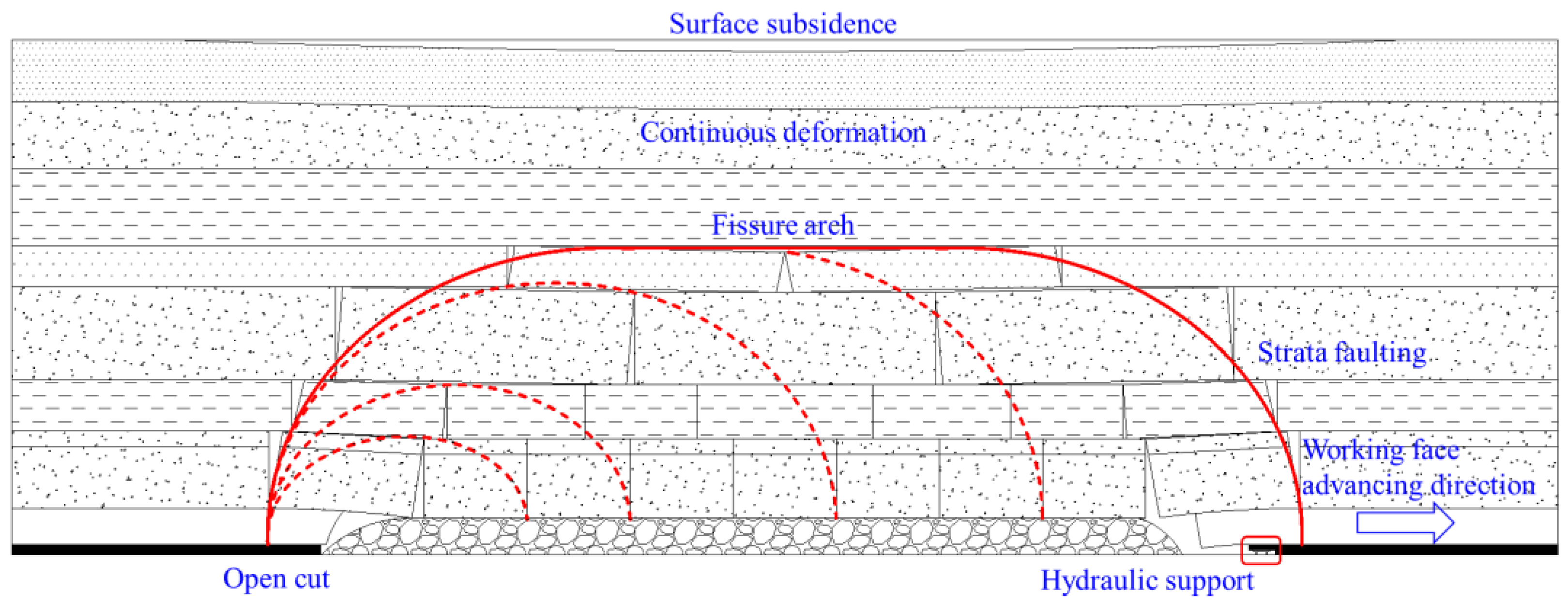
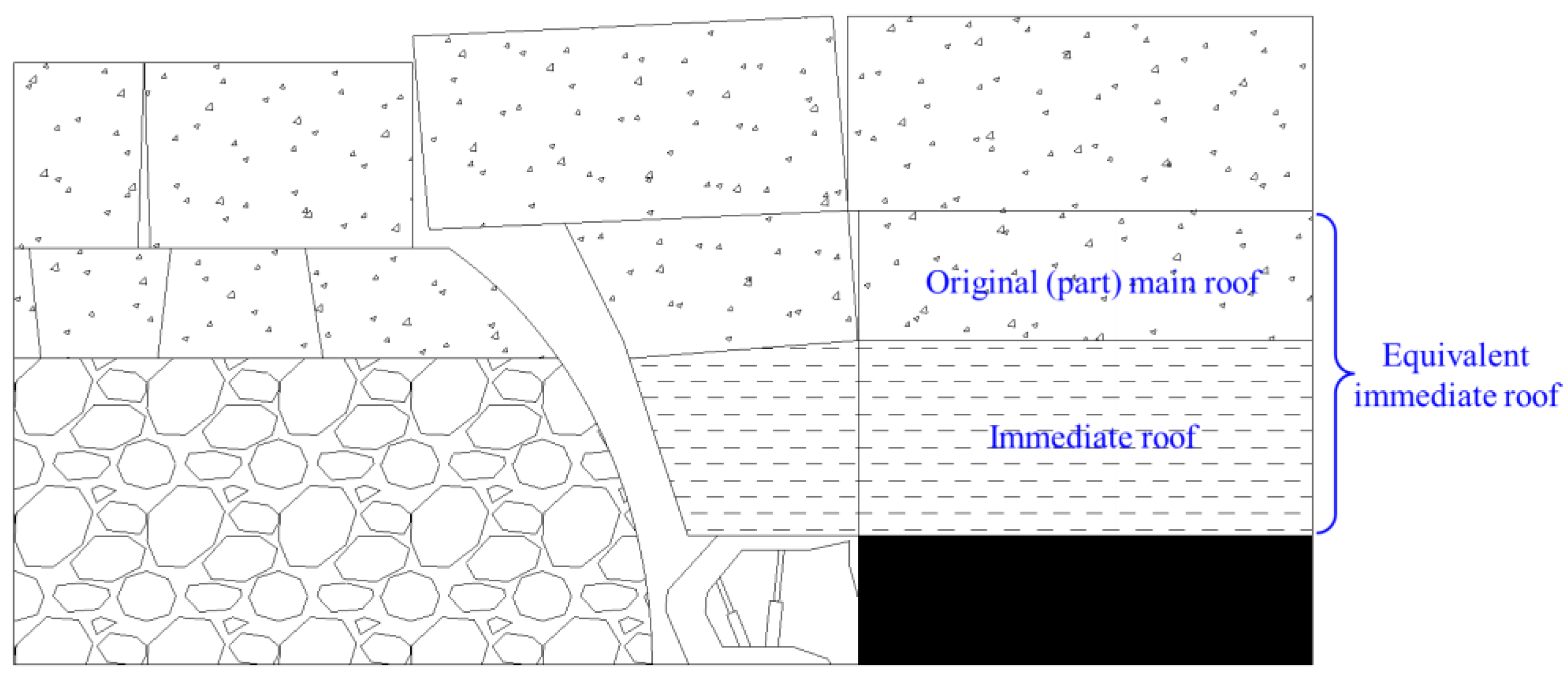
2.1. Roof Movement Deformation Mechanism of Ultra-Large Height Mining Face
2.2. Support–Surrounding Rock Relationship
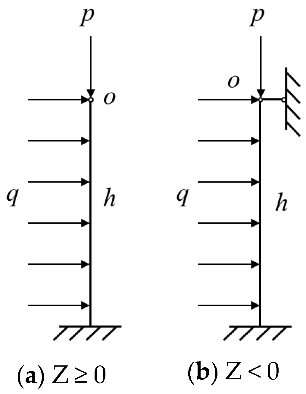
2.3. Analysis of Coal Wall Spalling Mechanism of Ultra-Large Height Mining Face
3. Stability Analysis of Supports
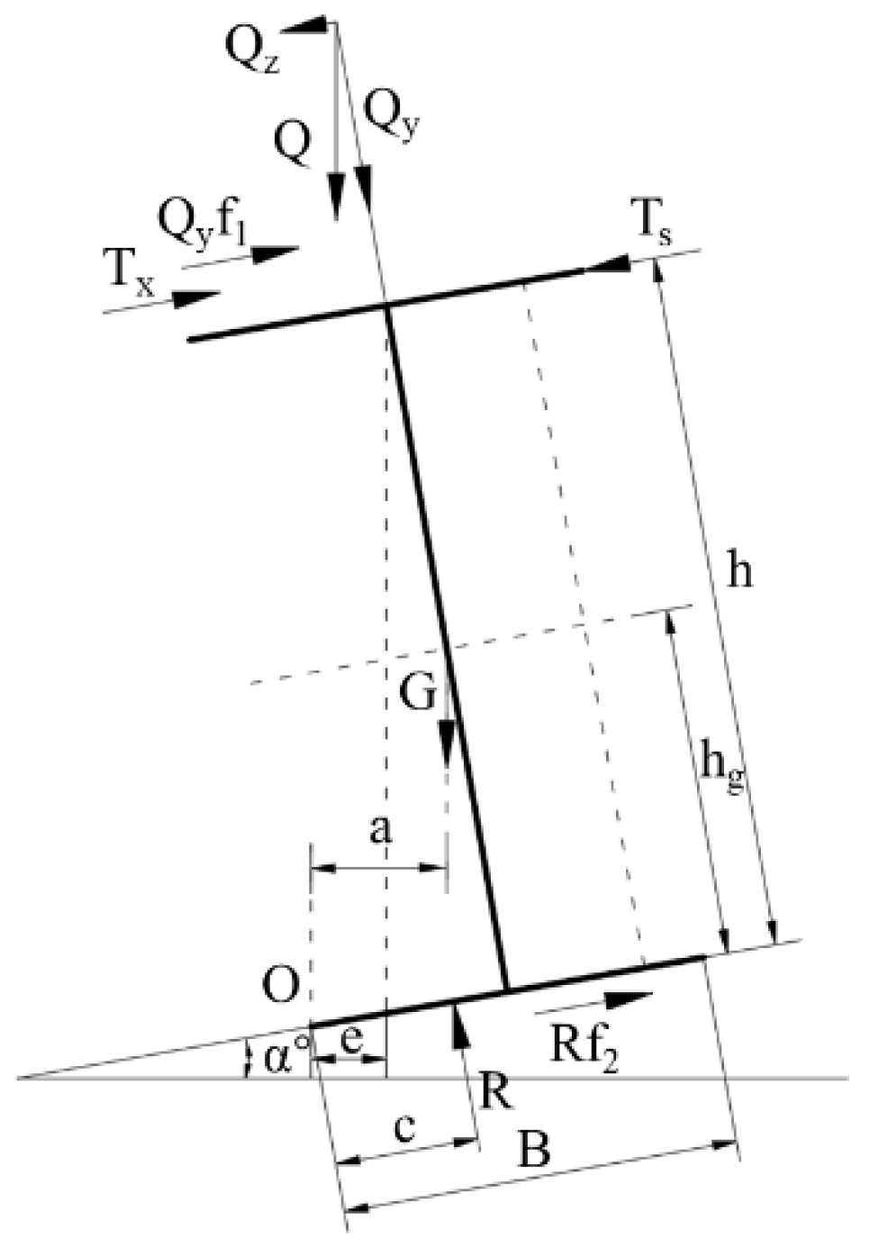
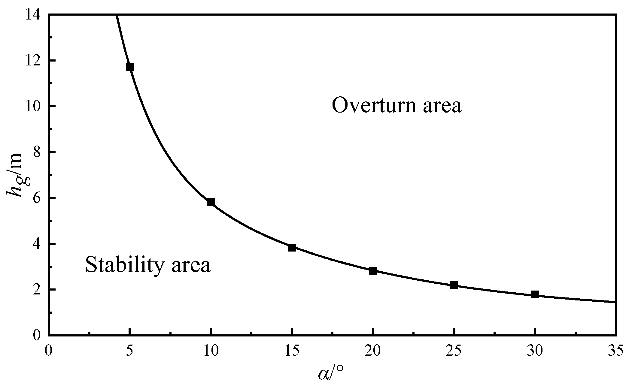
3.1. Overturning Stability Analysis of Ultra-Large Height Mining Face
3.2. Stability Analysis of Support Sliding in Super High Mining Face
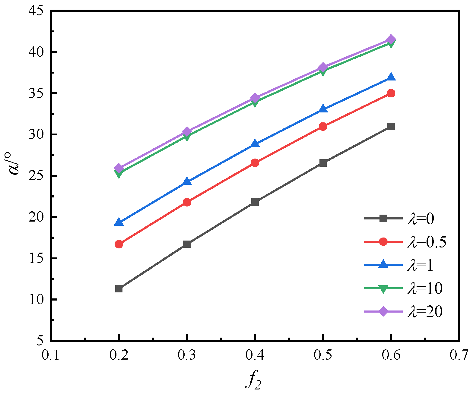
3.3. Factors Influencing the Stability of Super High Mining Face
- (1)
- Mining face inclination angle
- (2)
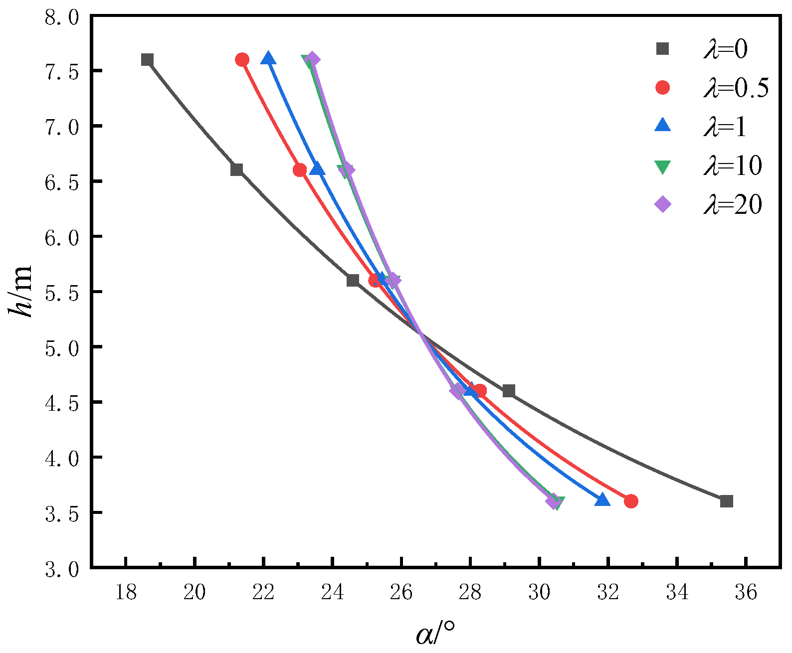
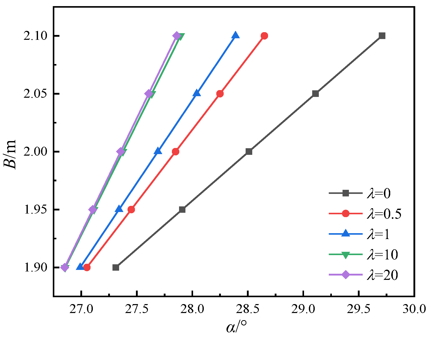
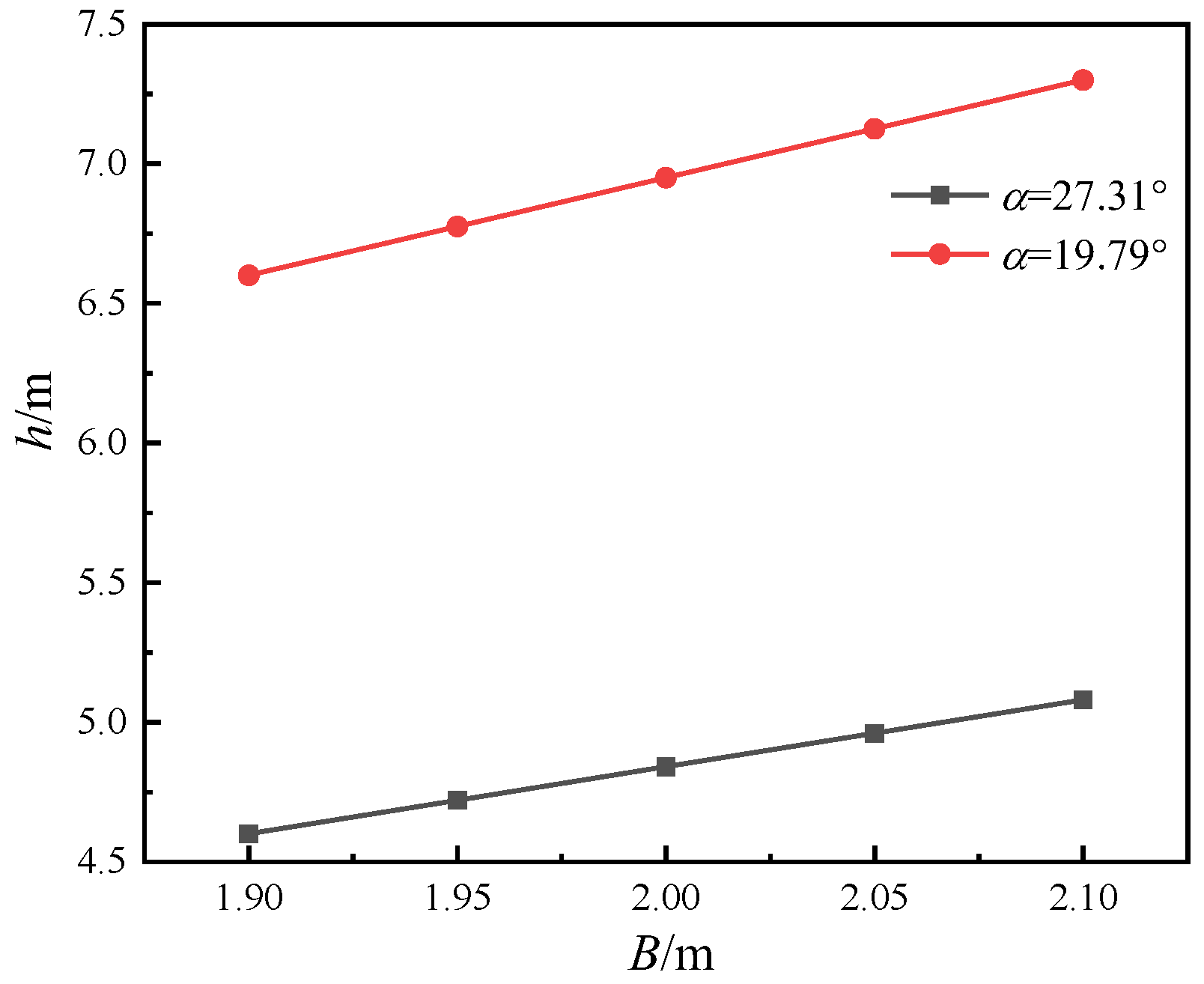
- Support structure
- (3)
- Stress state of support
4. Application of Super-Large Mining Height Fully Mechanized Support
4.1. Overview of Working Face
4.2. Determination of Support Parameters
- (1)
- First fracture of main rock beam
- (2)
- Periodic fracture of main rock beam
- (3)
- Determination of support strength
- (4)
- Determination of support type
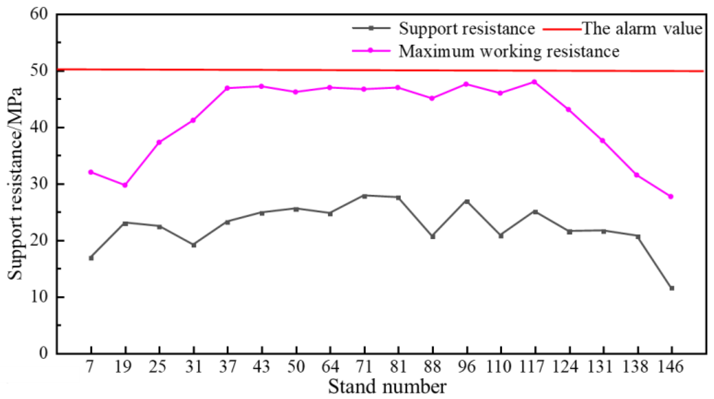
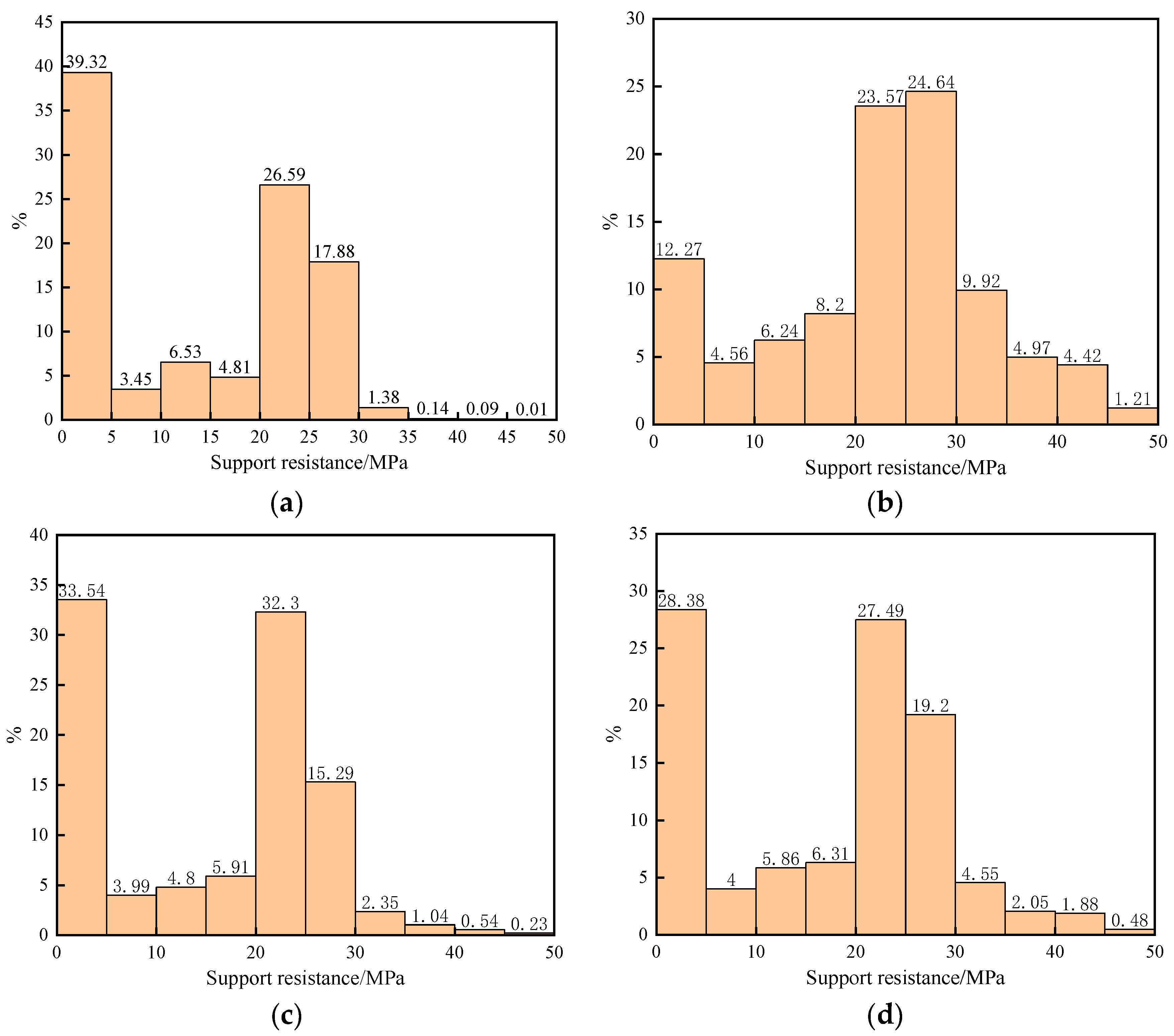
4.3. Correlation Analysis between Periodic Weighting and Support Load
5. Conclusions
- Due to the large increase in the mining thickness of the ultra-large height mining face, the working resistance of the support and the risk of coal wall spalling increased. The equivalent immediate roof is used to calculate the working resistance of the support, and the coal wall spalling is analyzed. It is required that the ultra-large mining height support should have high setting force, working resistance, and support force.
- The stability analysis of the supports shows that: When selecting the supports, the stability of the supports can be increased by reducing the support gravity center and widening the support base.
- The working resistance monitoring results show that: The average working resistance of support is 22.6 MPa, which meets the mining requirement of the mining face. The working resistance of the support’s load frequency in 0~5 MPa, accounting for a large proportion. It shows that the process of support moving is long, and the initial support force of the support is small. It is still necessary to strengthen management to give full play to the performance of the supports.
Author Contributions
Funding
Data Availability Statement
Conflicts of Interest
References
- Liu, H.Y.; Zhang, B.Y.; Li, X.L. Research on roof damage mechanism and control technology of gob-side entry retaining under close distance gob. Eng. Fail. Anal. 2022, 138, 106331. [Google Scholar] [CrossRef]
- Li, X.-L.; Chen, S.-J.; Liu, S.-M.; Li, Z.-H. AE waveform characteristics of rock mass under uniaxial loading based on Hilbert-Huang transform. J. Cent. South Univ. 2021, 28, 1843–1856. [Google Scholar] [CrossRef]
- Yin, X.W. Research status of strata control and large mining height fully-mechanized mining technology in China. Coal Sci. Technol. 2019, 47, 37–45. [Google Scholar]
- Kang, Y.S.; Liu, Q.S.; Gong, G.Q. Application of a combined support system to the weak floor reinforcement in deep underground coal mine. Int. J. Rock Mech. Min. Sci. 2014, 71, 143–150. [Google Scholar] [CrossRef]
- Zhou, X.M.; Wang, S.; Li, X.L. Research on theory and technology of floor heave control in semicoal rock roadway: Taking longhu coal mine in Qitaihe mining area as an Example. Lithosphere 2022, 2022, 3810988. [Google Scholar] [CrossRef]
- Zhao, G.; Zhang, B.; Zhang, L.; Liu, C.; Wang, S. Roof Fracture Characteristics and Strata Behavior Law of Super Large Mining Working Faces. Geofluids 2021, 2021, 1–12. [Google Scholar] [CrossRef]
- Du, T.; Nie, W.; Chen, D.; Xiu, Z.; Yang, B.; Liu, Q.; Guo, L. CFD Modeling of Coal Dust Migration in an 8.8-Meter-High Fully Mechanized Mining Face. Energy 2020, 212, 118616. [Google Scholar] [CrossRef]
- Li, M.; Zhang, J.-X.; Huang, Y.-L.; Gao, R. Measurement and numerical analysis of influence of key stratum breakage on mine pressure in top-coal caving face with super great mining height. J. Cent. South Univ. 2017, 24, 1881–1888. [Google Scholar] [CrossRef]
- Lu, C.; Xu, J.; Zhao, H.; Zhang, H.; Zhang, Y.; Chen, M. Floor Disturbance and Failure Characteristics of Super-Large Mining Height Working Face. Geofluids 2022, 2022, 1279642. [Google Scholar] [CrossRef]
- Ren, Z.; Zuo, M. Research on Technology of Supporting in Super-Large Section Cut in Working Face with Large Mining Height. Adv. Civ. Eng. 2021, 2021, 3304049. [Google Scholar] [CrossRef]
- Liu, C.; Li, H.; Mitri, H. Effect of Strata Conditions on Shield Pressure and Surface Subsidence at a Longwall Top Coal Caving Working Face. Rock Mech. Rock Eng. 2019, 52, 1523–1537. [Google Scholar] [CrossRef]
- Xie, P.S.; Wu, Y.P.; Wang, H.W. Stability analysis of incline masonry structure and support around longwall mining face area in steeply dipping seam. J. China Coal Soc. 2012, 37, 1275–1280. [Google Scholar]
- Wang, D.L.; Zeng, X.T.; Wang, G.F.; Li, R. Stability of a face guard in a large mining height working face. Int. J. Simul. Model. 2021, 20, 547–558. [Google Scholar] [CrossRef]
- Wang, J.C.; Wang, Z.H. Systematic principles of surrounding rock control in longwall mining within thick coal seams. Int. J. Min. Sci. Technol. 2019, 29, 64–70. [Google Scholar] [CrossRef]
- Guo, C.H.; Mao, J. Anti-impact load characteristics of two-stage safety valve for hydraulic support. Ain Shams Eng. J. 2022, 13, 101738. [Google Scholar] [CrossRef]
- Liang, M.; Fang, X.; Li, S.; Wu, G.; Ma, M.; Zhang, Y. A fiber Bragg grating tilt sensor for posture monitoring of hydraulic supports in coal mine working face. Measurement 2019, 138, 305–313. [Google Scholar] [CrossRef]
- Wang, Z.H.; Wang, J.C.; Yang, Y.; Tang, Y.S.; Wang, L. Mechanical relation between support stiffness and longwall face stability with in fully-mechanized mining faces. J. China Univ. Min. Technol. 2019, 48, 258–267. [Google Scholar]
- Yang, K.; Chi, X.L.; Liu, S. Instability mechanism and control of hydraulic support in fully mechanized longwall mining with large dip. J. China Coal Soc. 2018, 43, 1821–1828. [Google Scholar]
- Zeng, X.T.; Meng, G.Y.; Zhou, J.H. Analysis on the pose and dynamic response of hydraulic support under dual impact loads. Int. J. Simul. Model. 2018, 17, 69–80. [Google Scholar] [CrossRef]
- Meng, Z.S.; Zhang, J.M.; Xie, Y.Y.; Lu, Z.G.; Zeng, Q.L. Analysis of the force response of a double-canopy hydraulic support under impact loads. Int. J. Simul. Model. 2021, 20, 766–777. [Google Scholar] [CrossRef]
- Zhang, K.; Li, Y.; Feng, L.; Meng, X.; Zhong, D.; Huang, L. Roof deformation characteristics and experimental verification of advanced coupling support system supporting roadway. Energy Sci. Eng. 2022, 10, 2397–2419. [Google Scholar] [CrossRef]
- Xie, S.R.; Li, S.J.; Wei, Z.; Sun, Y.J.; Zhang, G.C.; Song, B.H.; He, F.L.; Tian, C.Y. Stability control of support-surrounding rock system during fully mechanized caving face crossing abandoned roadway period. J. China Coal Soc. 2015, 40, 502–508. [Google Scholar]
- Cheng, J.-Y.; Zhang, Y.-D.; Cheng, L.; Ji, M.; Gu, W.; Gao, L.-S. Study of loading and running characteristic of hydraulic support in underhand mining face. Arch. Min. Sci. 2017, 62, 215–224. [Google Scholar] [CrossRef]
- Wang, X.; Yang, Z.; Feng, J.; Liu, H. Stress analysis and stability analysis on doubly-telescopic prop of hydraulic support. Eng. Fail. Anal. 2013, 32, 274–282. [Google Scholar] [CrossRef]
- Kong, D.Z.; Cheng, Z.B.; Zheng, S.S. Study on the failure mechanism and stability control measures in a large-cutting-height coal mining face with a deep-buried seam. Bull. Eng. Geol. Environ. 2019, 78, 6143–6157. [Google Scholar] [CrossRef]
- Duan, H.; Zhao, L. Prevention Technology for Strong Mine Pressure Disaster in the Hard-Roof Large-Mining-Height Working Face. Shock Vib. 2020, 2020, 8846624. [Google Scholar] [CrossRef]
- Yang, Z.K.; Sun, Z.; Jiang, S.B.; Mao, Q.H.; Liu, P.; Xu, C.Z. Structural analysis on impact-mechanical properties of ultra-high hydraulic support. Int. J. Simul. Model. 2020, 19, 17–28. [Google Scholar] [CrossRef]
- Yuan, Y. Stability control mechanism of support-surrounding rocks at fully mechanized mining face with great cutting height. J. China Coal Soc. 2011, 36, 1955–1956. [Google Scholar]
- Wu, F.-F.; Liu, C.-Y.; Yang, J.-X. Mode of overlying rock roofing structure in large mining height coal face and analysis of support resistance. J. Cent. South Univ. 2016, 23, 3262–3272. [Google Scholar] [CrossRef]
- Yuan, H.H.; Shan, R.L.; Su, X.G. Deformation characteristics and stability control of a gateroad in fully mechanized mining with large mining height. Arab. J. Geosci. 2018, 11, 767. [Google Scholar] [CrossRef]
- Zhang, Q.; Yue, J.; Liu, C.; Feng, C.; Li, H. Study of automated top-coal caving in extra-thick coal seams using the continuum-discontinuum element method. Int. J. Rock Mech. Min. Sci. 2019, 122, 104033. [Google Scholar] [CrossRef]
- Meng, Z.; Zeng, Q.; Gao, K.; Kong, S.; Liu, P.; Wan, L. Failure analysis of super-large mining height powered support. Eng. Fail. Anal. 2018, 92, 378–391. [Google Scholar] [CrossRef]
- Wu, F.; Yue, X.; Yang, J.; Du, B.; Zhang, J.; Lv, B. Model of overlying strata structure in large mining height excavating condition and calculation of support working resistance. Geofluids 2022, 2022, 5894735. [Google Scholar] [CrossRef]
- Pang, Y.; Wang, G.; Yao, Q. Double-factor control method for calculating hydraulic support working resistance for longwall mining with large mining height. Arab. J. Geosci. 2020, 13. [Google Scholar] [CrossRef]
- Li, H.; Kang, T.H.; Li, X.B.; Yang, Y.K.; Wu, L.L. Study on setting load of powered support in high cutting fully-mechanized coal mining face affected to coal wall stability. Coal Sci. Technol. 2016, 44, 67–71, 92. [Google Scholar]
- Wang, G.F.; Li, X.Y.; Zhang, C.C.; Ren, H.W. Research and development and application of set equipment of 8 m large mining height fully—Mechanized face. Coal Sci. Technol. 2017, 45, 1–8. [Google Scholar]
- Wang, G.F.; Pang, Y.H.; Li, M.Z.; Ma, Y.; Liu, X.H. Hydraulic support and coal wall coupling relationship in ultra large height mining face. J. China Coal Soc. 2017, 42, 518–526. [Google Scholar]
- Pang, Y.H.; Wang, G.F. Hydraulic support with large mining height structural optimal design and adaptability analysis. J. China Coal Soc. 2017, 42, 2518–2527. [Google Scholar]
- Gong, P.L.; Jin, Z.M. Study on the structure characteristics and movement laws of overlying strata with large mining height. J. China Coal Soc. 2004, 1, 7–11. [Google Scholar]
- Ralston, J.; Reid, D.; Hargrave, C.; Hainsworth, D. Sensing for advancing mining automation capability: A review of underground au-tomation technology development. Int. J. Min. Sci. Technol. 2014, 24, 305–310. [Google Scholar] [CrossRef]
- Yan, S.H.; Yin, X.W.; Hu, G.J.; Liu, Q.M. Roof structure of short cantilever-articulated rock beam and calculation of support resistance in full-mechanized face with large mining height. J. China Coal Soc. 2011, 36, 1816–1820. [Google Scholar]
- Li, X.L.; Chen, S.J.; Wang, S. Study on in situ stress distribution law of the deep mine taking Linyi Mining area as an example. Adv. Mater. Sci. Eng. 2021, 9, 5594181. [Google Scholar] [CrossRef]


| h/m | 3.6 | 4.6 | 5.6 | 6.6 | 7.6 |
| α/° | 15.9–35.4 | 12.6–29.1 | 10.4–24.6 | 8.8–21.2 | 7.7–18.6 |
| h | 4.6 m | 5.6 m | 6.6 m | 7.6 m | |
|---|---|---|---|---|---|
| αo | 27.63° | 24.59° | 21.22° | 18.63° | |
| f2 = 0.2 | αs | 11.3° | 11.3° | 11.3° | 11.3° |
| α | 11.3° | 11.3° | 11.3° | 11.3° | |
| f2 = 0.3 | αs | 16.7° | 16.7° | 16.7° | 16.7° |
| α | 16.7° | 16.7° | 16.7° | 16.7° | |
| f2 = 0.4 | αs | 21.8° | 21.8° | 21.8° | 21.8° |
| α | 21.8° | 21.8° | 21.22° | 18.63° | |
| f2 = 0.5 | αs | 26.6° | 26.6° | 26.6° | 26.6° |
| α | 26.6° | 24.59° | 21.22° | 18.63° | |
| f2 = 0.6 | αs | 31° | 31° | 31° | 31° |
| α | 27.63° | 24.59° | 21.22° | 18.63° | |
| α | 16.7° | 24.2° | 29.8° | 30.4° |
| Fkh | 0 | 14,079.70 kN | 24,350.70 kN | 25,372.20 kN |
| Pattern | Standing Shield Hydraulic Support |
|---|---|
| Height (lowest/highest) | 3800/8200 mm |
| Total weight of support | 78.3 t |
| Center distance | 2050 mm |
| Working resistance | 21,000 kN |
| Support strength | ≥1.65 Mpa |
| Floor specific pressure | ≤5.0 Mpa |
| Initial support force | 16,546 kN |
| Maneuverability pattern | Electrohydraulic control |
| Step distance | 865 mm |
| Leg piece | Three telescopic (2 columns) |
| Pressure Station Number | Working Resistance P/MPa | Pressure Criterion /P + σ | Reasonable Support Strength/P + 2σ |
|---|---|---|---|
| 4 | 22 | 31 | 39 |
| 6 | 23 | 30 | 37 |
| 9 | 14 | 23 | 33 |
| 11 | 28 | 35 | 41 |
| 13 | 21 | 31 | 42 |
| 16 | 21 | 27 | 33 |
| 17 | 25 | 32 | 40 |
| mean value | 22.00 | 29.86 | 37.86 |
Publisher’s Note: MDPI stays neutral with regard to jurisdictional claims in published maps and institutional affiliations. |
© 2022 by the authors. Licensee MDPI, Basel, Switzerland. This article is an open access article distributed under the terms and conditions of the Creative Commons Attribution (CC BY) license (https://creativecommons.org/licenses/by/4.0/).
Share and Cite
Wang, S.; Li, X.; Qin, Q. Study on Surrounding Rock Control and Support Stability of Ultra-Large Height Mining Face. Energies 2022, 15, 6811. https://doi.org/10.3390/en15186811
Wang S, Li X, Qin Q. Study on Surrounding Rock Control and Support Stability of Ultra-Large Height Mining Face. Energies. 2022; 15(18):6811. https://doi.org/10.3390/en15186811
Chicago/Turabian StyleWang, Sheng, Xuelong Li, and Qizhi Qin. 2022. "Study on Surrounding Rock Control and Support Stability of Ultra-Large Height Mining Face" Energies 15, no. 18: 6811. https://doi.org/10.3390/en15186811