
Improving Transient Stability of a Synchronous Generator Using UIPC with a Unified Control Scheme


 , and
, and
Abstract
:1. Introduction
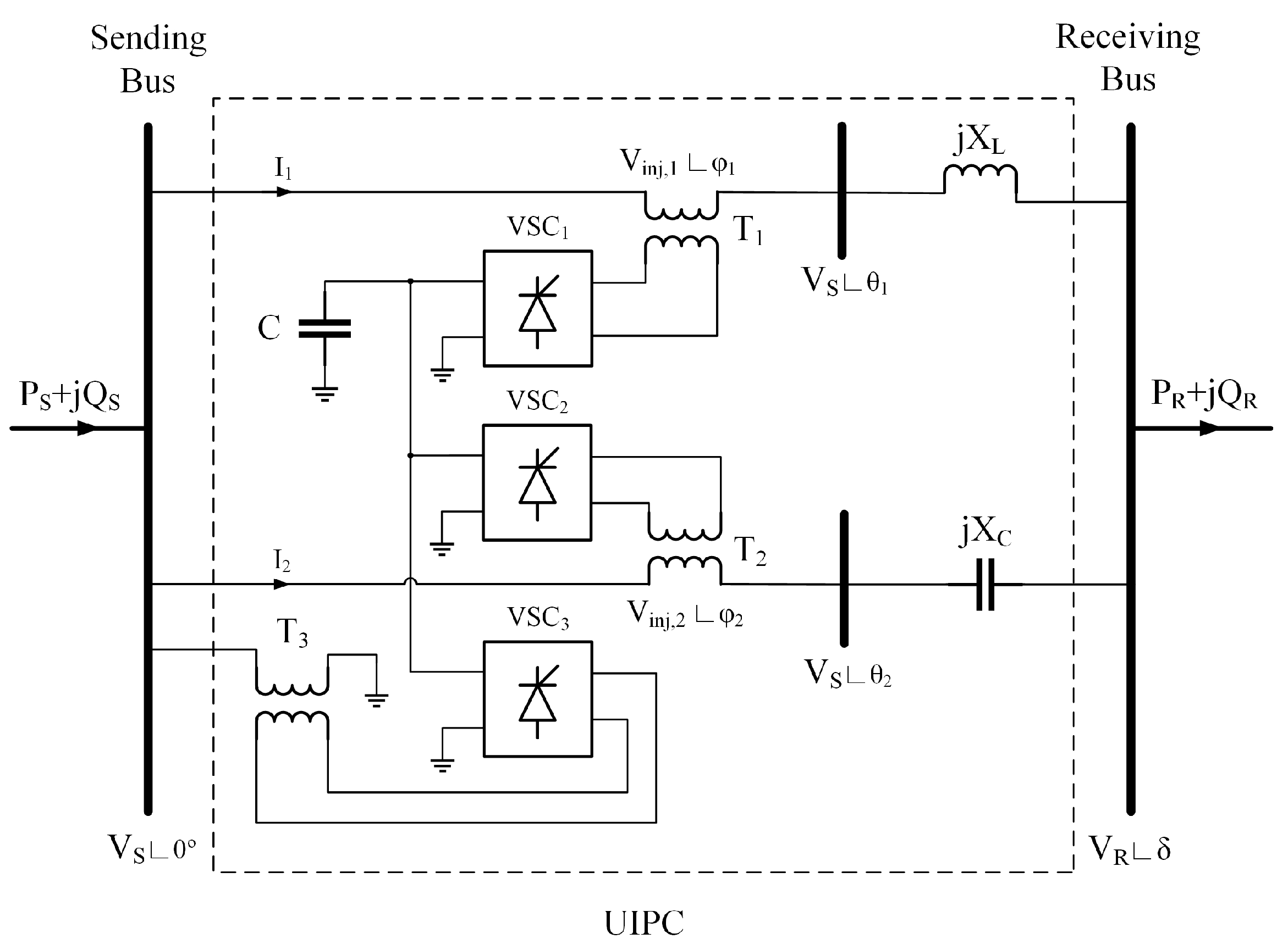
2. UIPC Operation
2.1. Normal Condition
2.2. Fault Condition
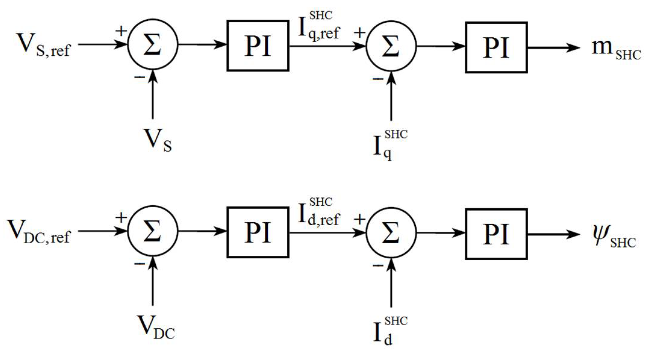
3. UIPC Control Scheme
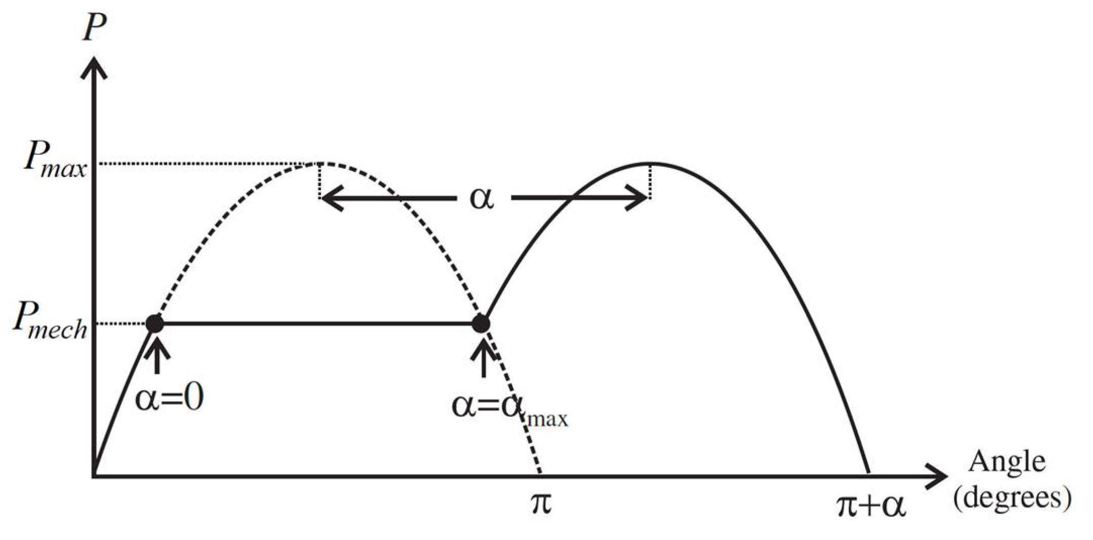
3.1. Power System Stability
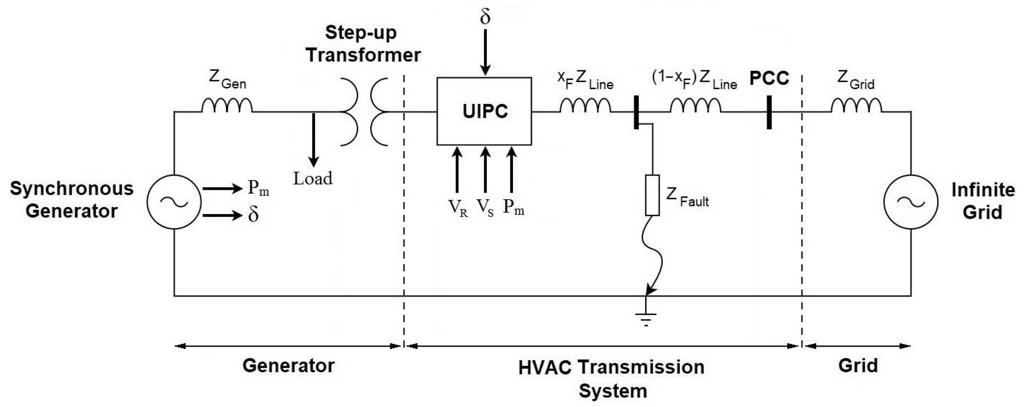
3.2. System Configuration
- Scenario 1: Three-phase to ground symmetrical fault;
- Scenario 2: Two-phase asymmetrical fault;
- Scenario 3: Three-phase fault with ground impedance.
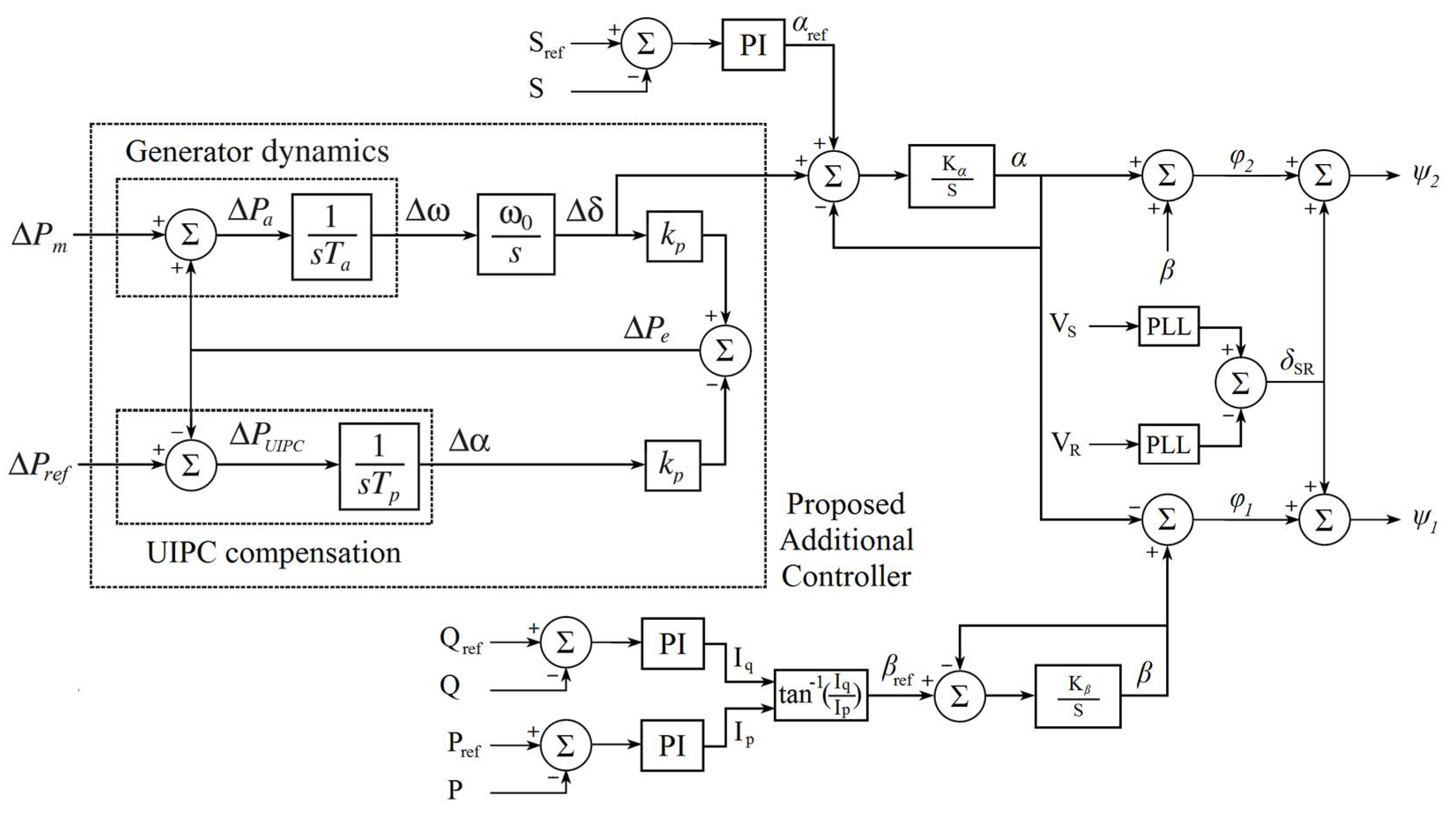
3.3. The Proposed Control Strategy
4. Results and Discussions
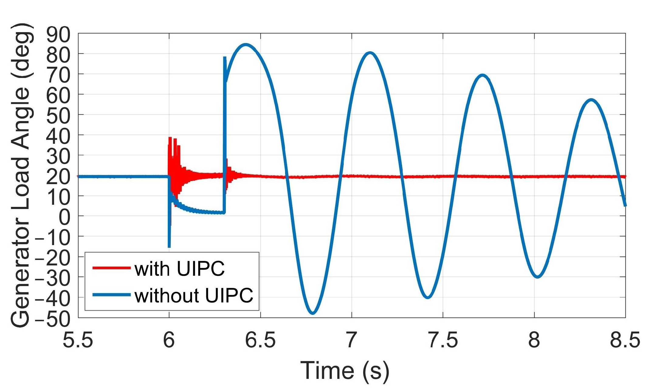
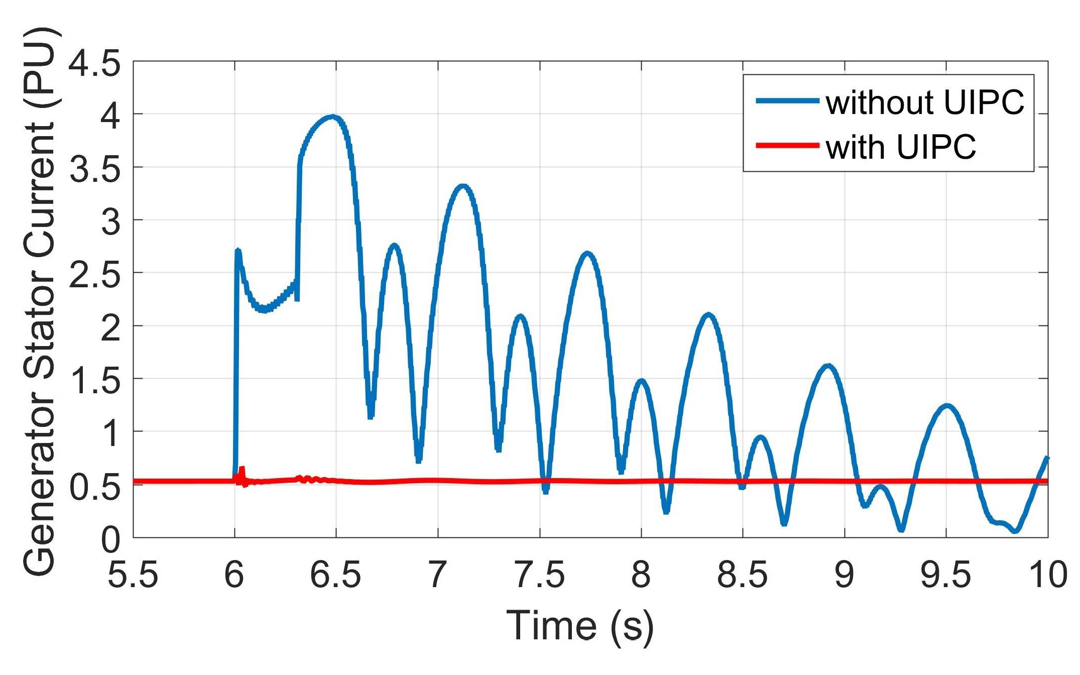
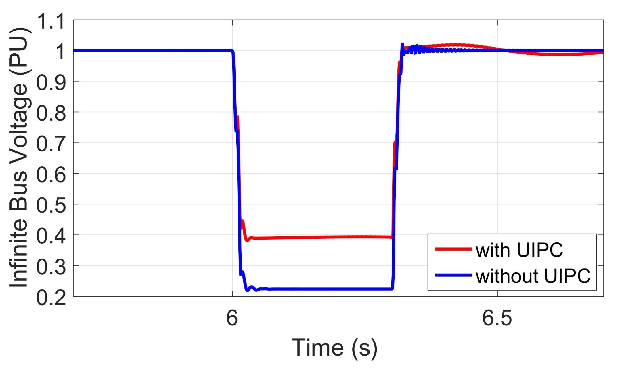
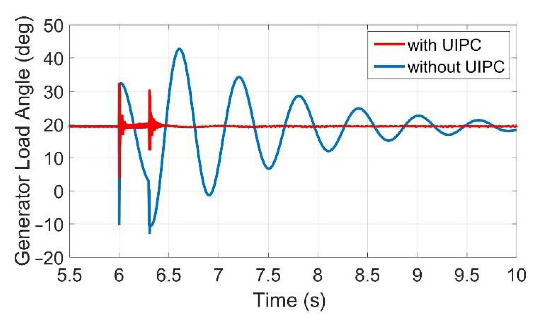
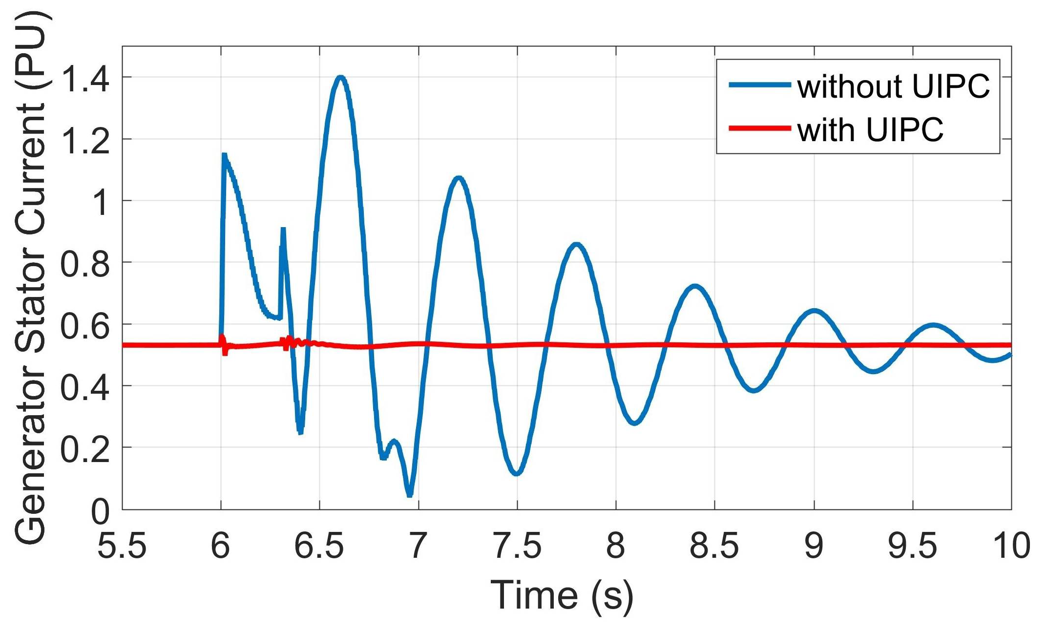
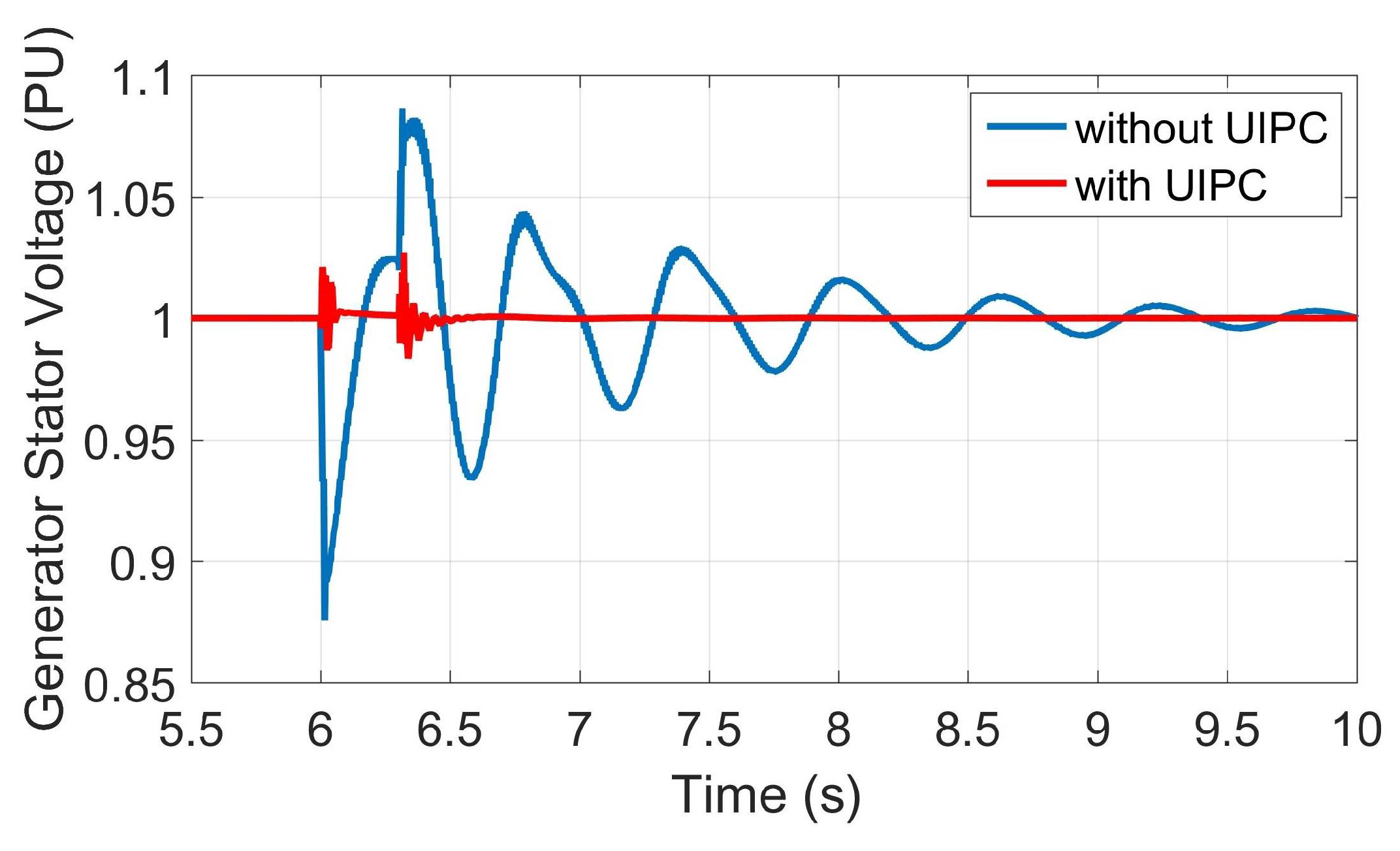
4.1. Three-Phase-to-Ground Symmetrical Fault
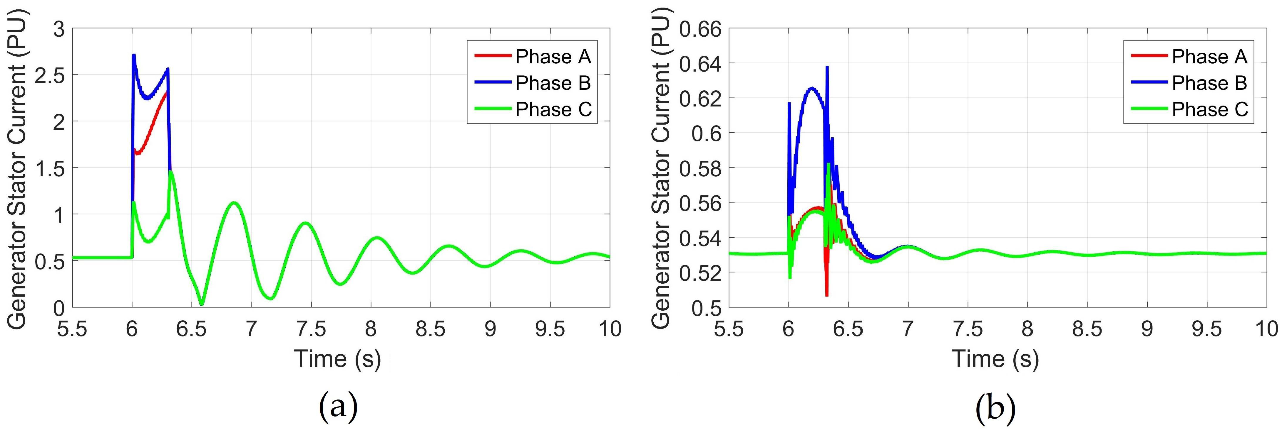
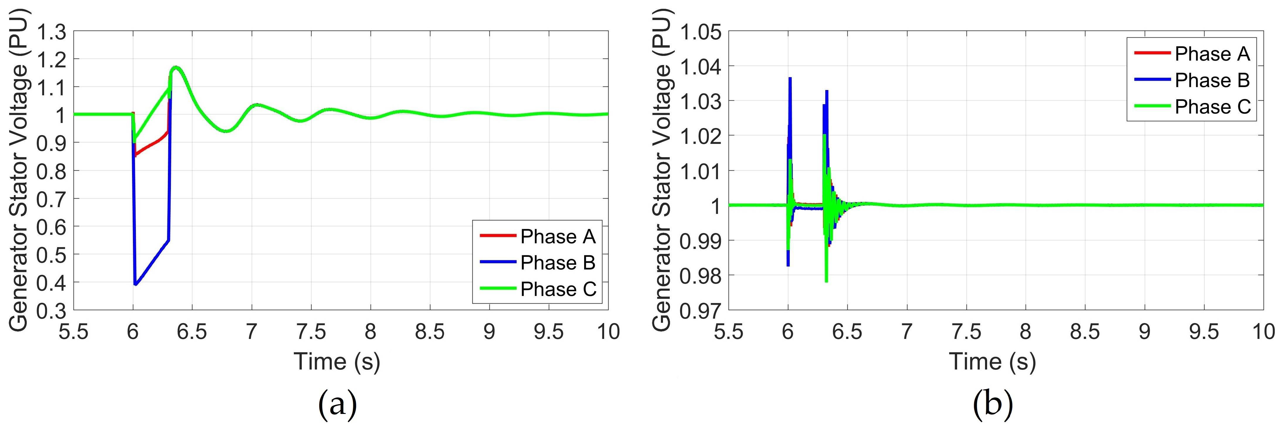
4.2. Two-Phase Asymmetrical Fault
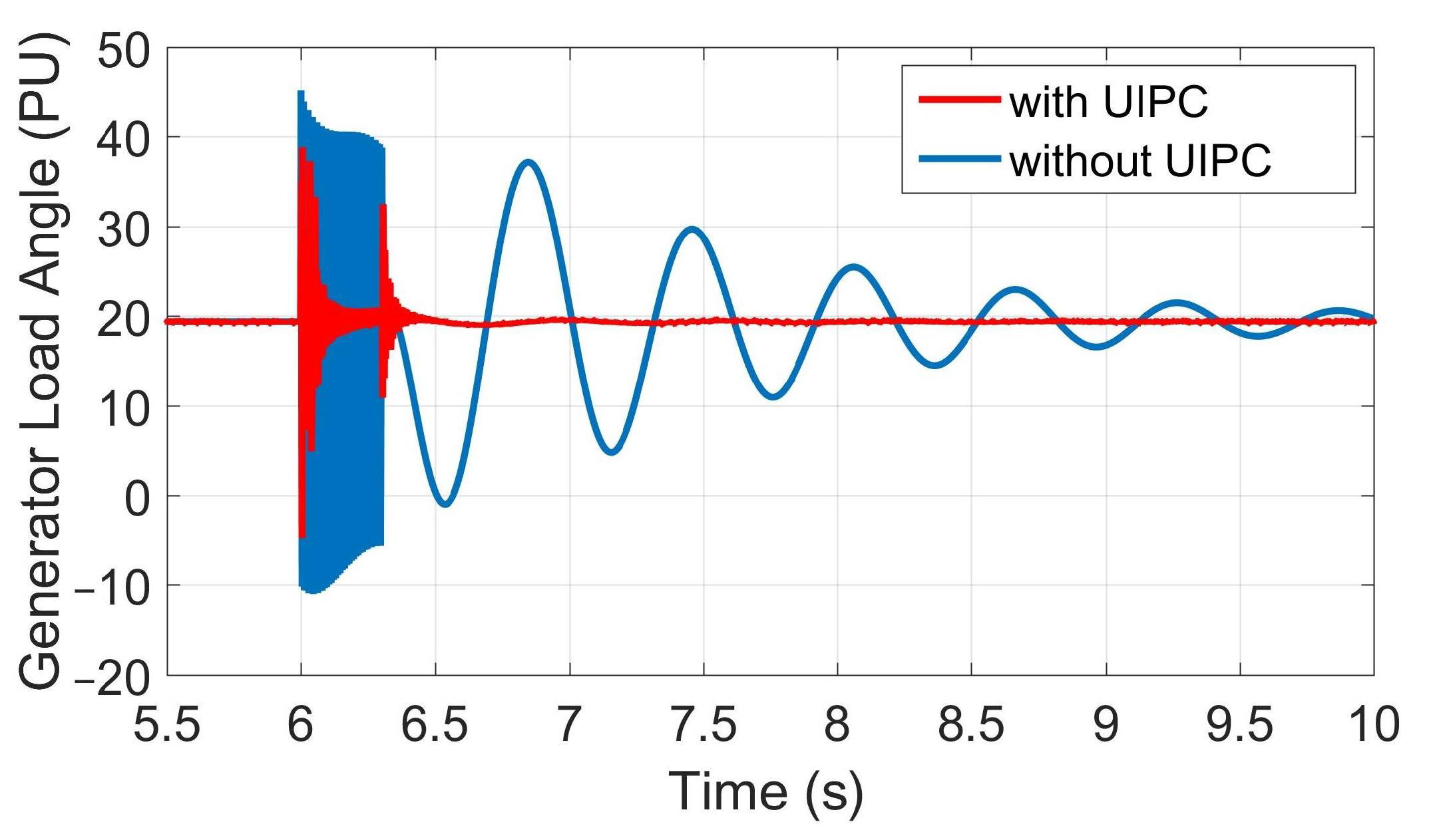
4.3. Three-Phase Fault with Ground Impedance
5. Conclusions
Author Contributions
Funding
Institutional Review Board Statement
Informed Consent Statement
Data Availability Statement
Conflicts of Interest
Nomenclature
| , , | Active, reactive, and apparent power delivered to the receiving bus, respectively |
| , | Active and reactive power sent from the sending bus, respectively |
| , | Voltage at the receiving and sending buses, respectively |
| , , | The UIPC current, its direct, and its quadrature component |
| , | The magnitude and phase angle of each SEC injected voltage, respectively |
| The phase angle of the receiving bus voltage, equal to the SG load angle | |
| Mechanical power delivered to SG rotor | |
| Electrical power drawn from SG stator | |
| The SG stator terminal voltage | |
| The SG stator reactance | |
| The DC capacitor voltage | |
| , | The firing angles of the SECs |
| , | The modulation index and firing angle of the SHC |
| The SG mechanical startup time | |
| The UIPC controller time-constant |
References
- Milano, F.; Manjavacas, Á.O. Frequency-Dependent Model for Transient Stability Analysis. IEEE Trans. Power Syst. 2018, 34, 806–809. [Google Scholar] [CrossRef] [Green Version]
- Alizadeh, M.; Khodabakhshi-Javinani, N.; Gharehpetian, G.; Askarian-Abyaneh, H. Performance analysis of distance relay in presence of unified interphase power controller and voltage-source converters. IET Gen. Trans. Dist. 2015, 9, 1642–1651. [Google Scholar] [CrossRef]
- Eladany, M.M.; Eldesouky, A.A.; Sallam, A.A. Power system transient stability: An algorithm for assessment and enhancement based on catastrophe theory and FACTS devices. IEEE Access 2018, 6, 26424–26437. [Google Scholar] [CrossRef]
- Firouzi, M.; Gharehpetian, G.B.; Mozafari, S.B. Application of UIPC to improve power system stability and LVRT capability of SCIG-based wind farms. IET Gen. Trans. Dist. 2017, 11, 2314–2322. [Google Scholar] [CrossRef]
- Müller, T.; See, C.; Ghani, A.; Bati, A.; Thiemann, P. Direct flux control–sensorless control method of PMSM for all speeds–basics and constraints. Electron. Lett. 2017, 53, 1110–1111. [Google Scholar] [CrossRef] [Green Version]
- Murali, D.; Rajaram, M.; Reka, N. Comparison of FACTS devices for power system stability enhancement. Int. J. Comput. Appl. 2010, 8, 30–35. [Google Scholar] [CrossRef]
- Wibawa, B.C.; Prastiantono, A.; Aryani, D.R.; Setiabudy, R.; Husnayain, F. Transient stability improvement by FACTS devices: A Comparison between STATCOM and SSSC in an extra high voltage transmission system. IOP Conf. Ser. Mater. Sci. Eng. 2019, 673, 012068. [Google Scholar] [CrossRef]
- Gaur, D.; Mathew, L. Optimal placement of FACTS devices using optimization techniques: A review. IOP Conf. Ser. Mater. Sci. Eng. 2018, 331, 012023. [Google Scholar] [CrossRef]
- Pourhossein, J.; Gharehpetian, G.; Fathi, S. Unified interphase power controller (UIPC) modeling and its comparison with IPC and UPFC. IEEE Trans. Power Deliv. 2012, 27, 1956–1963. [Google Scholar] [CrossRef]
- Firouzi, M.; Gharehpetian, G.B.; Mozafari, B. Power-flow control and short-circuit current limitation of wind farms using unified interphase power controller. IEEE Trans. Power Deliv. 2016, 32, 62–71. [Google Scholar] [CrossRef]
- Firouzi, M.; Gharehpetian, G.B.; Salami, Y. Active and reactive power control of wind farm for enhancement transient stability of multi-machine power system using UIPC. IET Renew. Power Gen. 2017, 11, 1246–1252. [Google Scholar] [CrossRef]
- Majlesi, A.; Miveh, M.R.; Ghadimi, A.A.; Kalam, A. Low Voltage Ride Through Controller for a Multi-Machine Power System Using a Unified Interphase Power Controller. Electronics 2021, 10, 585. [Google Scholar] [CrossRef]
- Zolfaghari, M.; Abedi, M.; Gharehpetian, G.B. Power exchange control of clusters of multiple AC and DC microgrids interconnected by UIPC in hybrid microgrids. In Proceedings of the 2019 24th Electrical Power Distribution Conference (EPDC), Khoramabad, Iran, 19–20 June 2019; pp. 22–26. [Google Scholar]
- Zolfaghari, M.; Gharehpetian, G.B.; Anvari-Moghaddam, A. Quasi-Luenberger observer-based robust DC link control of UIPC for flexible power exchange control in hybrid microgrids. IEEE Syst. J. 2020, 15, 2845–2854. [Google Scholar] [CrossRef]
- Zolfaghari, M.; Abedi, M.; Gharehpetian, G.B. Power Flow Control of Interconnected AC-DC Microgrids in Grid-Connected Hybrid Microgrids Using Modified UIPC. IEEE Trans. Smart Grid 2019, 10, 6298–6307. [Google Scholar] [CrossRef]
- Brochu, J.; Beauregard, F.; Lemay, J.; Morin, G.; Pelletier, P.; Thallam, R. Application of the interphase power controller technology for transmission line power flow control. IEEE Trans. Power Deliv. 1997, 12, 888–894. [Google Scholar] [CrossRef]
- Zhang, Y.; Chen, C. A novel power injection model of IPFC for power flow analysis inclusive of practical constraints. IEEE Trans. Power Syst. 2006, 21, 1550–1556. [Google Scholar] [CrossRef] [Green Version]
- Piwko, R.; Miller, N.; Girad, R.; MacDowell, J.; Clark, K.; Murdoch, A. Generator fault tolerance and grid codes. IEEE Power Energy Mag. 2010, 8, 18–26. [Google Scholar] [CrossRef]
- Kothari, D.P.; Nagrath, I.J. Electric Machines; Tata McGraw-Hill Education: New York, NY, USA, 2004. [Google Scholar]
- Khan, M.A.U.; Booth, C.D. Detailed analysis of the future distribution network protection issues. J. Eng. 2018, 2018, 1150–1154. [Google Scholar] [CrossRef]
- Raju, R.G.G.; Subramaniam, N. Transient stability analysis employing equal area criterion. In Proceedings of the 2011 1st International Conference on Electrical Energy Systems, Chennai, India, 3–5 January 2011; pp. 275–280. [Google Scholar]
- Sharma, S.; Pushpak, S.; Chinde, V.; Dobson, I. Sensitivity of transient stability critical clearing time. IEEE Trans. Power Syst. 2018, 33, 6476–6486. [Google Scholar] [CrossRef] [Green Version]
- Eremia, M.; Shahidehpour, M. Handbook of Electrical Power System Dynamics: Modeling, Stability, and Control; John Wiley & Sons: Hoboken, NJ, USA, 2013; Volume 92. [Google Scholar]
- Movahedi, A.; Niasar, A.H.; Gharehpetian, G.B. LVRT improvement and transient stability enhancement of power systems based on renewable energy resources using the coordination of SSSC and PSSs controllers. IEEE Trans. Smart Grid 2019, 13, 1849–1860. [Google Scholar] [CrossRef]
- Blanquez, F.; Revuelta, P.; Rebollo, E.; Platero, C. Validation study of the use of MATLAB/Simulink synchronous-machine block for accurate power-plant stability studies. In Proceedings of the 2014 14th International Conference on Environment and Electrical Engineering, Krakow, Poland, 10–12 May 2014; pp. 122–126. [Google Scholar]
- Taul, M.G.; Wang, X.; Davari, P.; Blaabjerg, F. An overview of assessment methods for synchronization stability of grid-connected converters under severe symmetrical grid faults. IEEE Trans. Power Electron. 2019, 34, 9655–9670. [Google Scholar] [CrossRef] [Green Version]
- Marconato, R. Dynamic Behaviour, Stability and Emergency Controls. In Electric Power System; Italian Electrotechnical Committee (CEI) Standards: Rome, Italy, 2008; Volume 3. [Google Scholar]


| Parameter | Value |
|---|---|
| System rated voltage | 230 kV |
| Generator rated power | 100 MW |
| Infinite grid rated power | 10 GW |
| Infinite grid impedance | 0.002 + j0.015 PU |
| Line length | 255 km |
| Line resistance per length | 0.025 Ω/km |
| Line inductance per length | 0.93 mH/km |
| Line capacitance per length | 0.013 F/km |
| Fault location (XF) | 40% |
| Parameter | Value |
|---|---|
| Rated power | 100 MW |
| DC bus voltage | 40 kV |
| DC link capacitor | 2.5 mF |
| X = XL = XC | 120 Ω |
Publisher’s Note: MDPI stays neutral with regard to jurisdictional claims in published maps and institutional affiliations. |
© 2022 by the authors. Licensee MDPI, Basel, Switzerland. This article is an open access article distributed under the terms and conditions of the Creative Commons Attribution (CC BY) license (https://creativecommons.org/licenses/by/4.0/).
Share and Cite
Ghafouri, S.; Hajiahmadi, M.A.; Firouzi, M.; Gharehpetian, G.B.; Mobayen, S.; Skruch, P. Improving Transient Stability of a Synchronous Generator Using UIPC with a Unified Control Scheme. Energies 2022, 15, 6072. https://doi.org/10.3390/en15166072
Ghafouri S, Hajiahmadi MA, Firouzi M, Gharehpetian GB, Mobayen S, Skruch P. Improving Transient Stability of a Synchronous Generator Using UIPC with a Unified Control Scheme. Energies. 2022; 15(16):6072. https://doi.org/10.3390/en15166072
Chicago/Turabian StyleGhafouri, Saeed, Mohammad Ali Hajiahmadi, Mehdi Firouzi, Gevork B. Gharehpetian, Saleh Mobayen, and Paweł Skruch. 2022. "Improving Transient Stability of a Synchronous Generator Using UIPC with a Unified Control Scheme" Energies 15, no. 16: 6072. https://doi.org/10.3390/en15166072