
Grid Forming Inverters: A Review of the State of the Art of Key Elements for Microgrid Operation


Abstract
:1. Introduction
Contribution and Organization of the Review
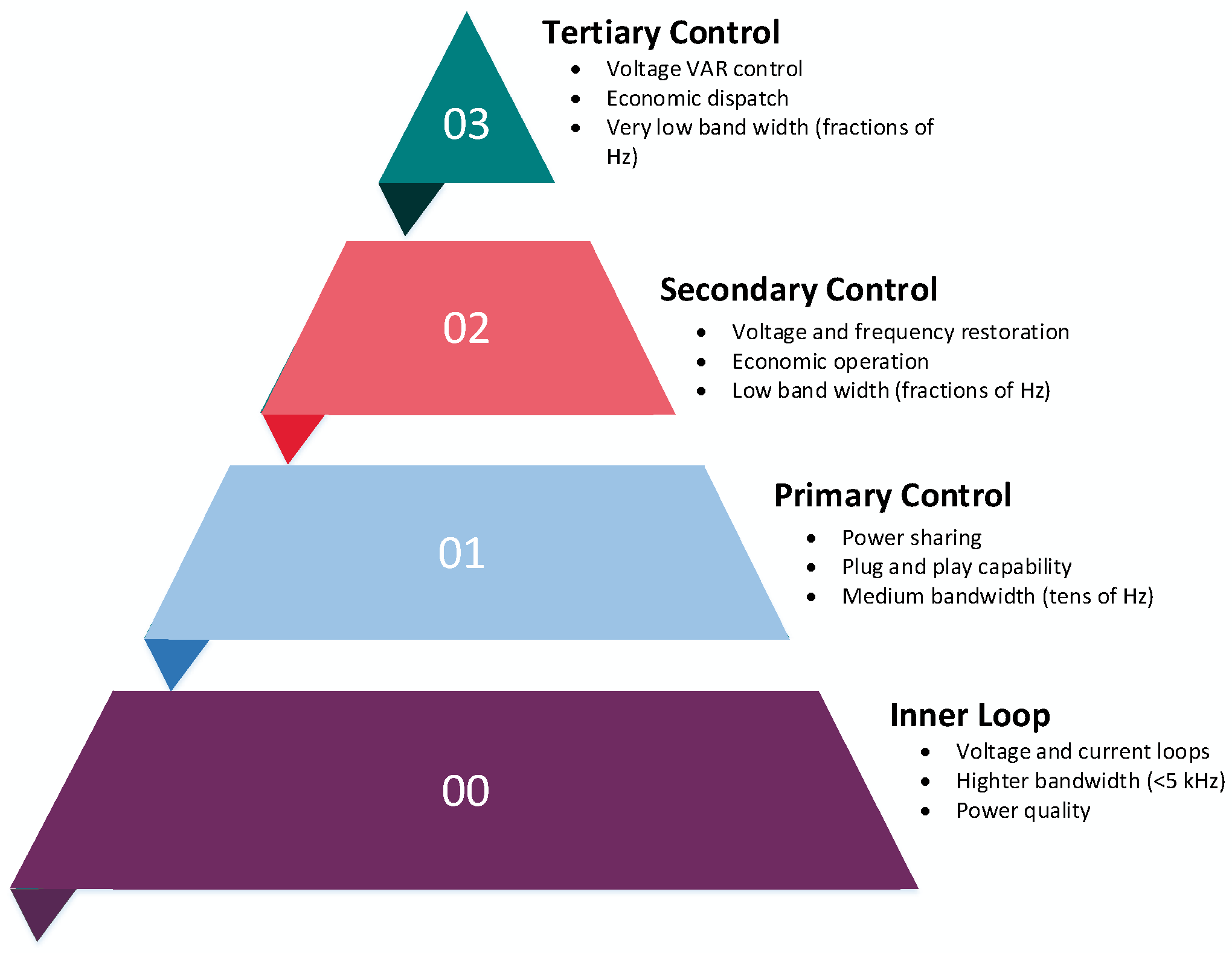
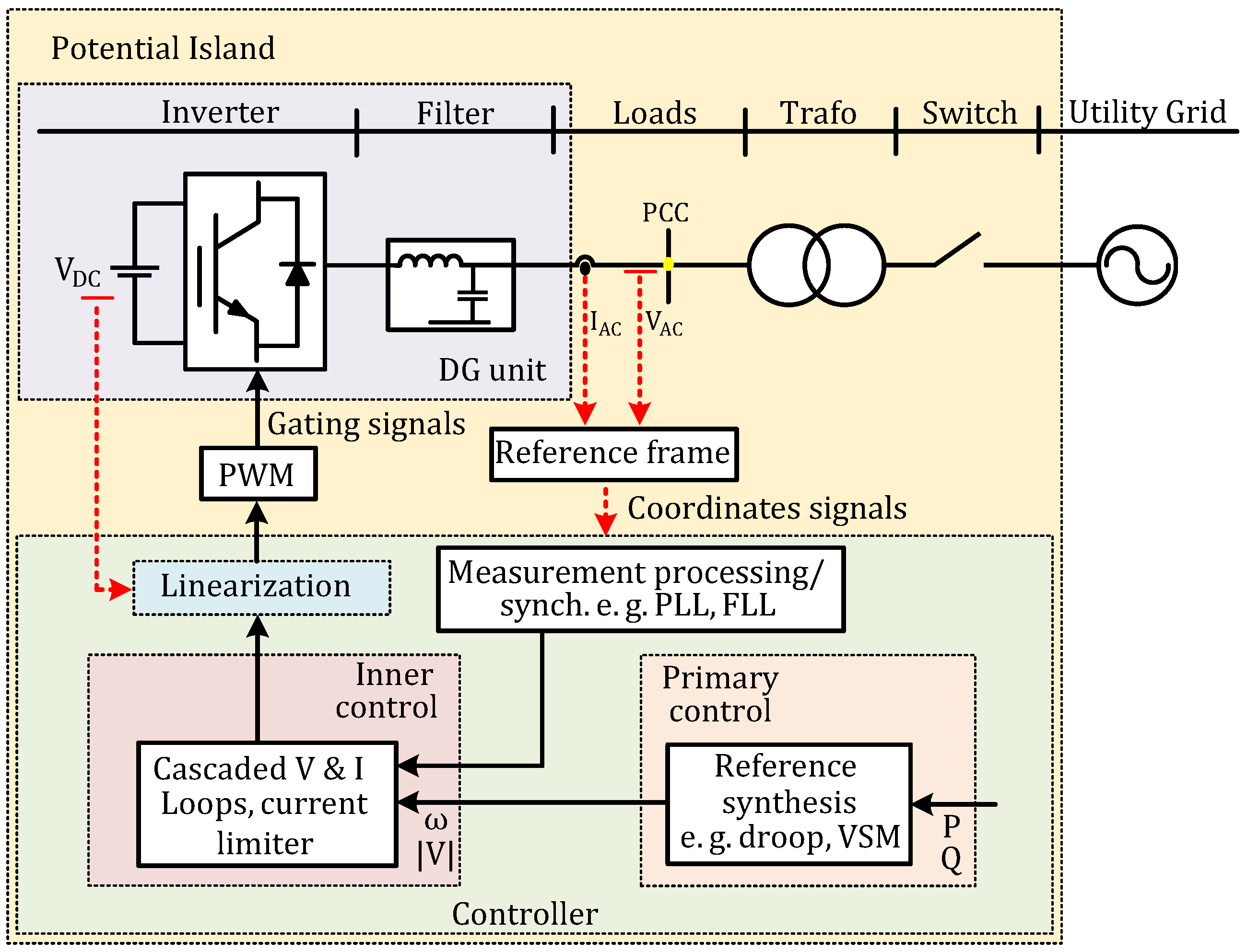
2. Background and Definitions
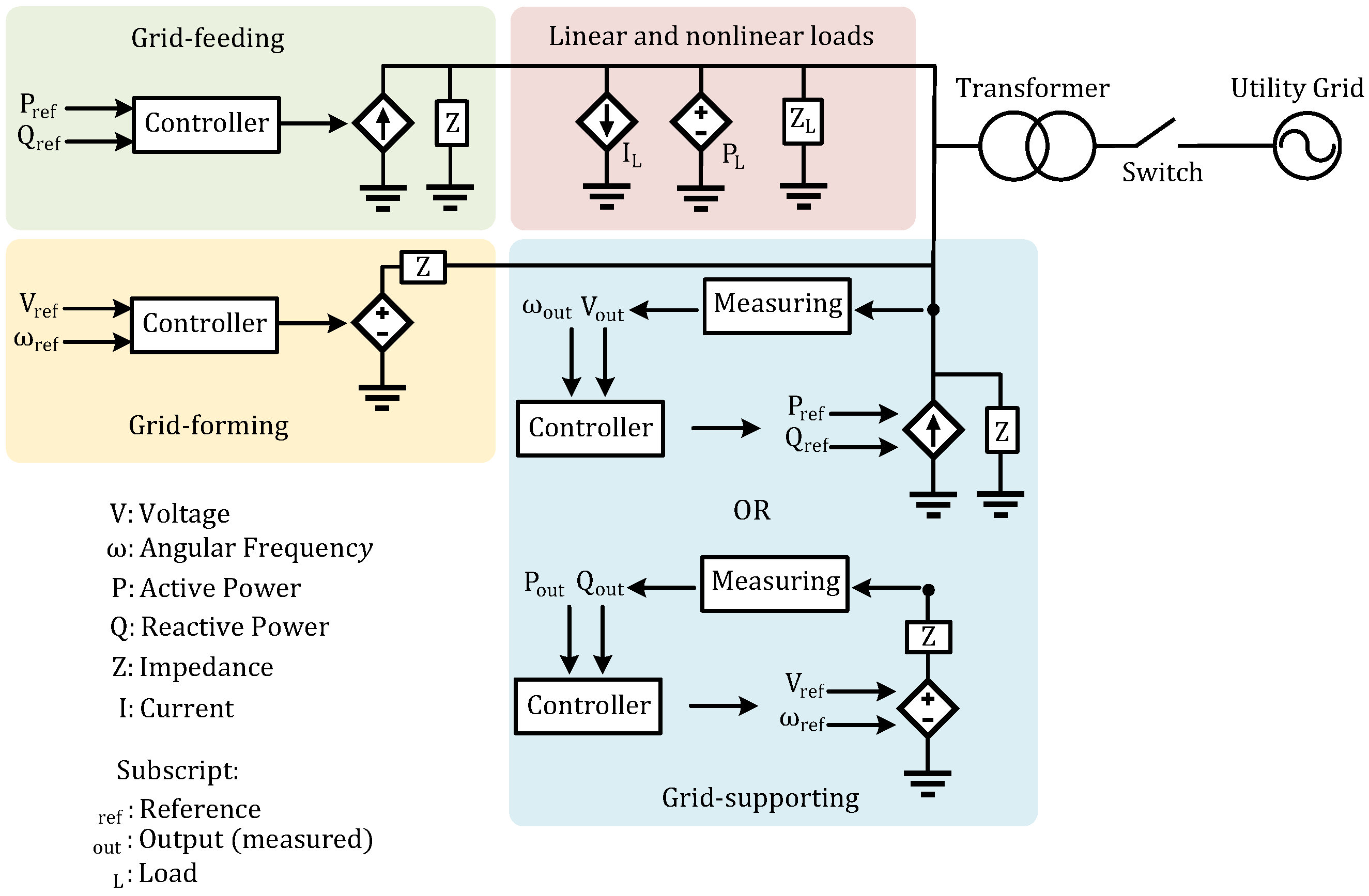
2.1. Categorization of Inverter Operation Mode
2.2. Defining Control Objectives for GFM Inverters
- Form the voltage amplitude and frequency in island operation;
- Operate in synchronization with the main grid in GC mode, either a VSI or CSI GS inverter;
- Be able to detect island and GC operation;
- Remain connected during transient events, i.e.,. have a proper current limiting strategy.
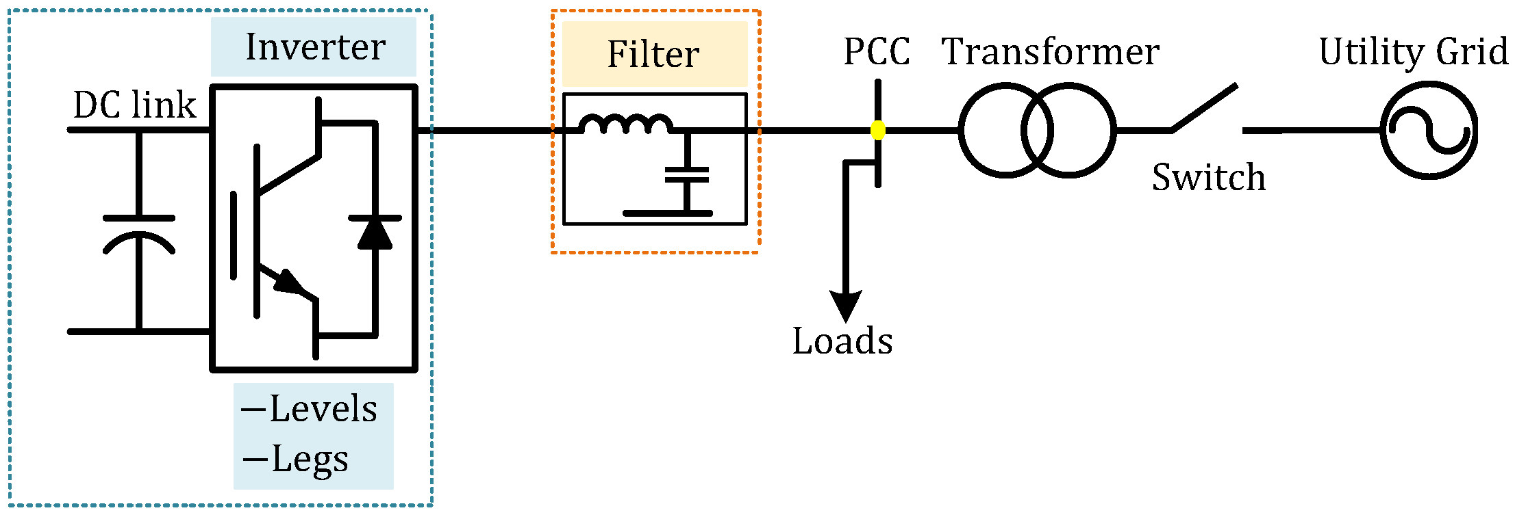
3. Gfm Inverter Topologies
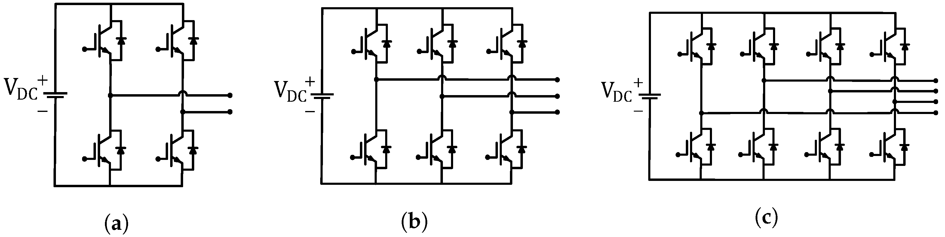
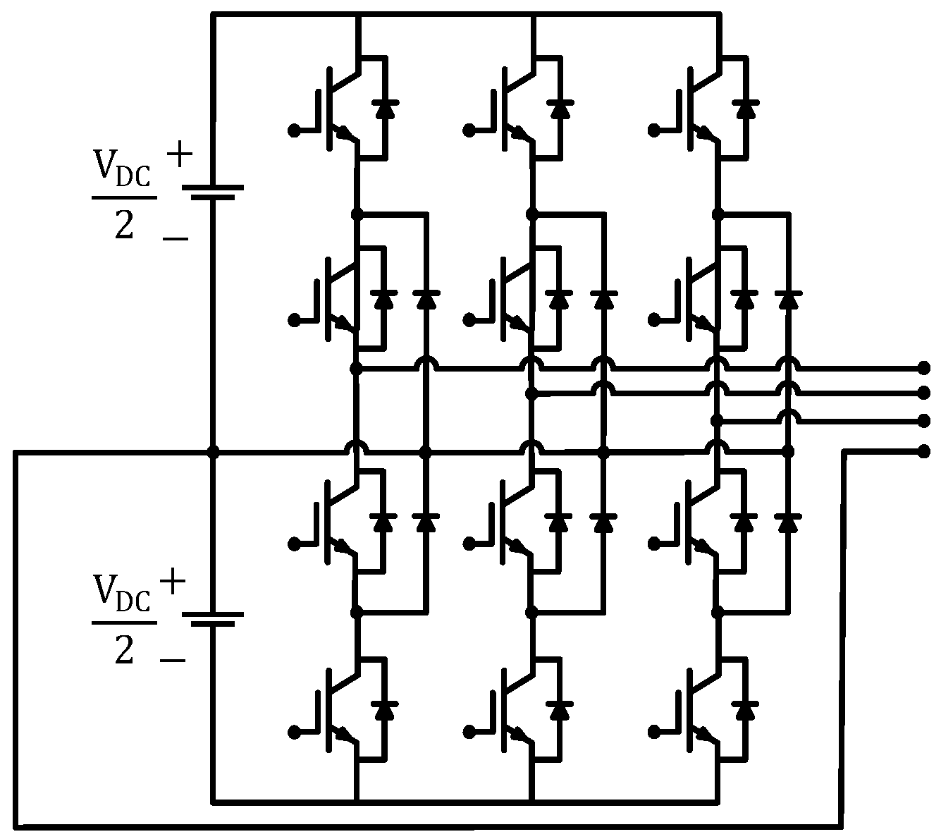
3.1. Number of Legs
3.2. Levels
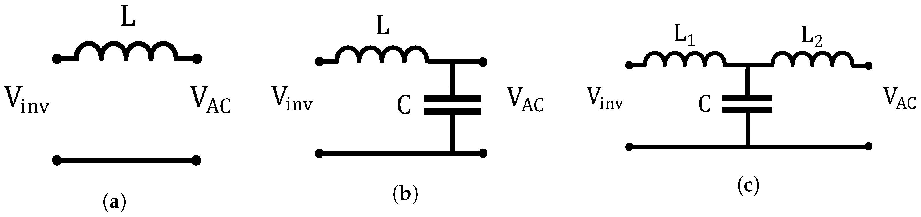
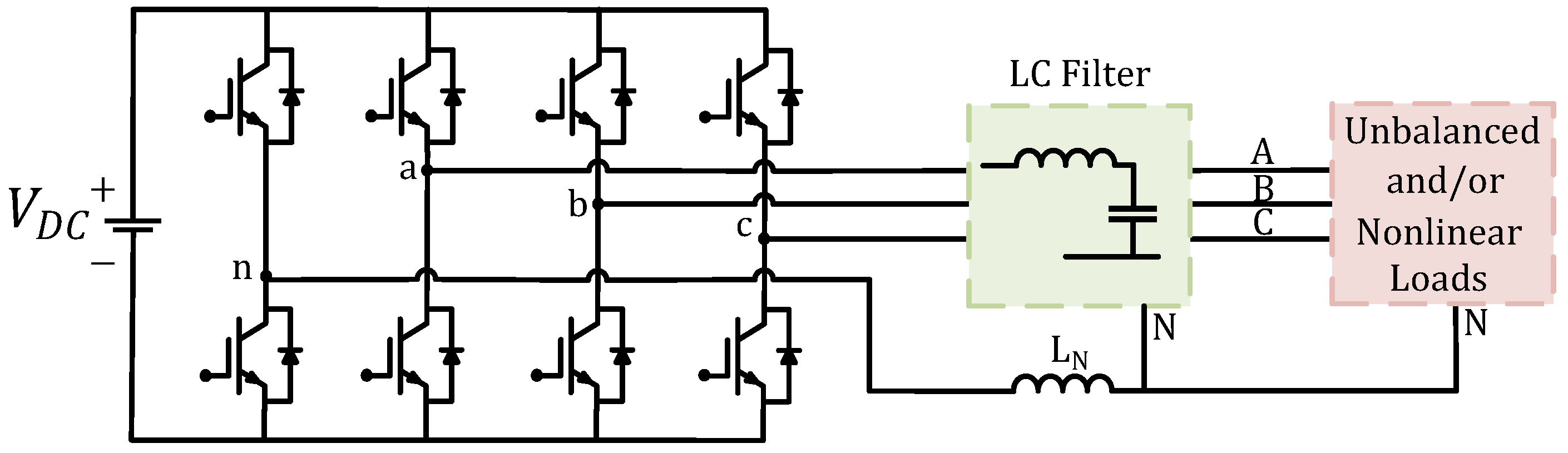
3.3. Filters
4. Control Strategies
4.1. Linearization
4.2. Inner Control
- Natural reference frame (abc);
- Synchronous reference frame (dq);
- Stationary reference frame ().
4.3. Primary Control
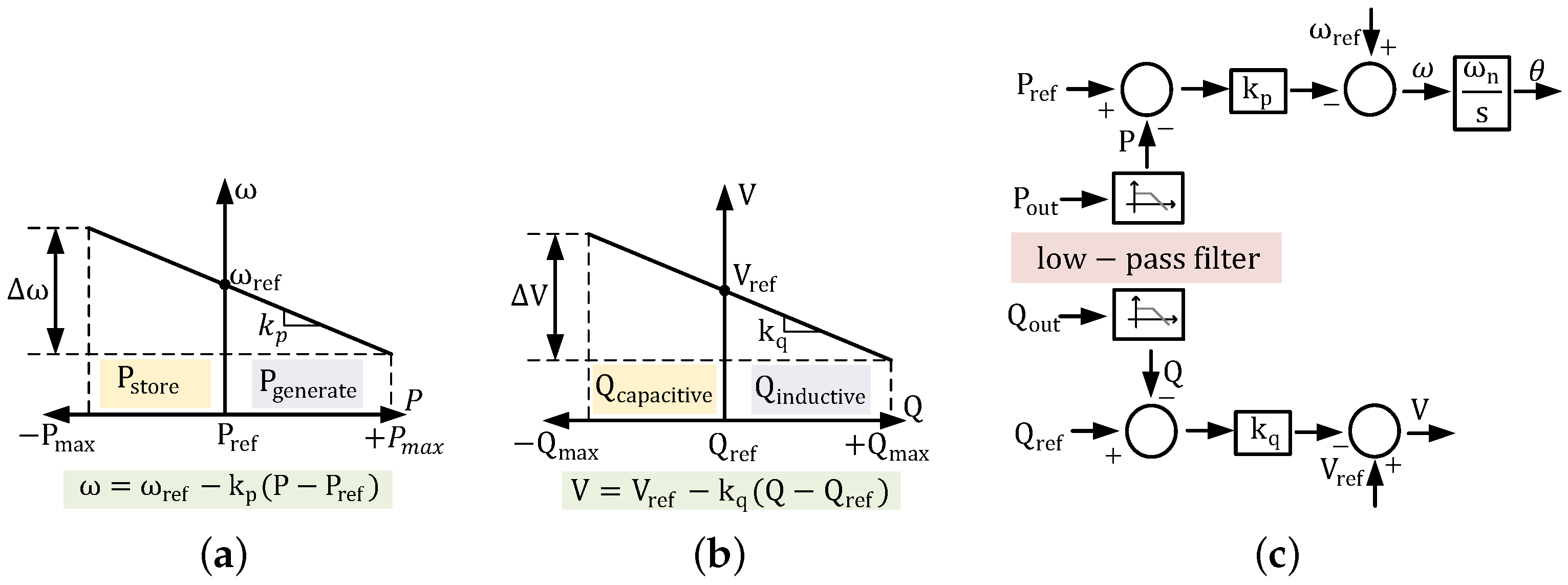
4.3.1. Droop Control
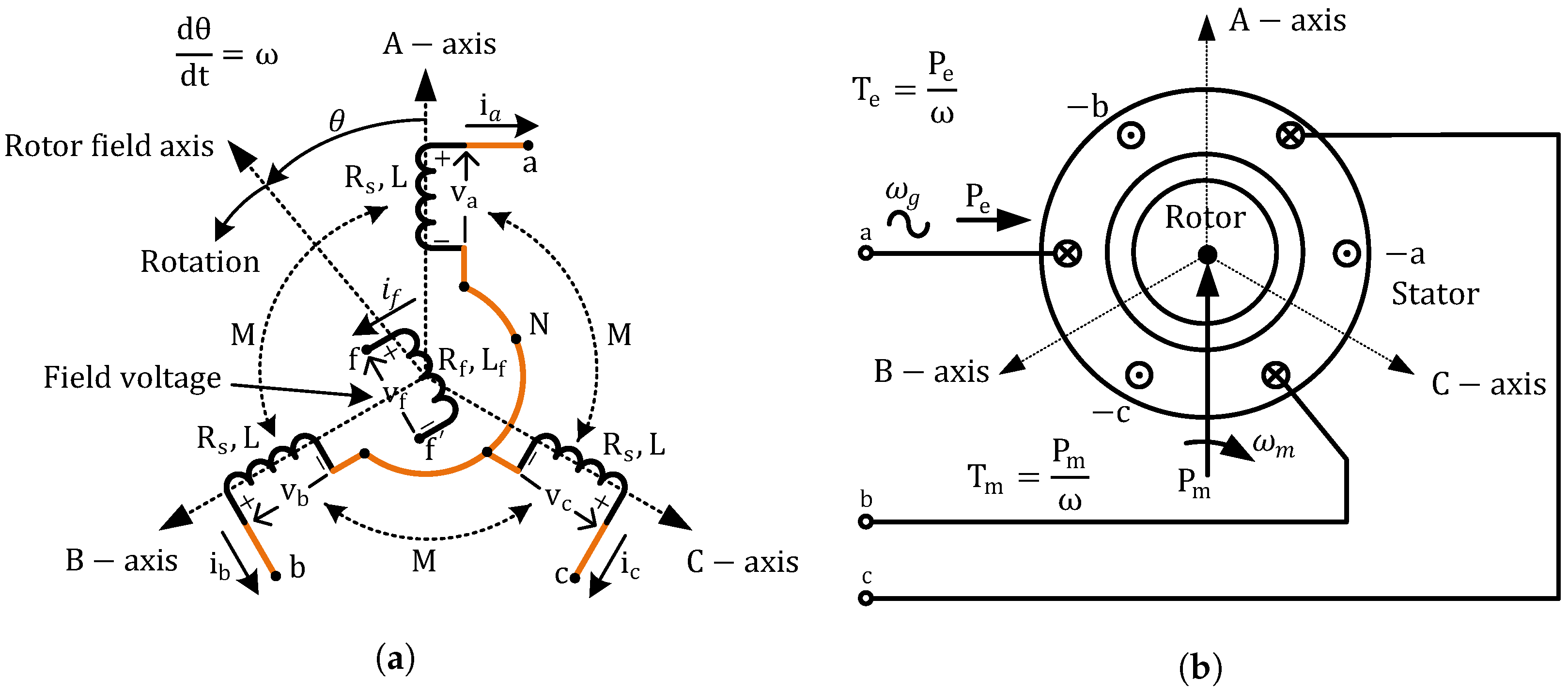
4.3.2. Virtual Synchronous Generator
Electrical Description of a VSG
Mechanical Description of a VSG
4.3.3. Others
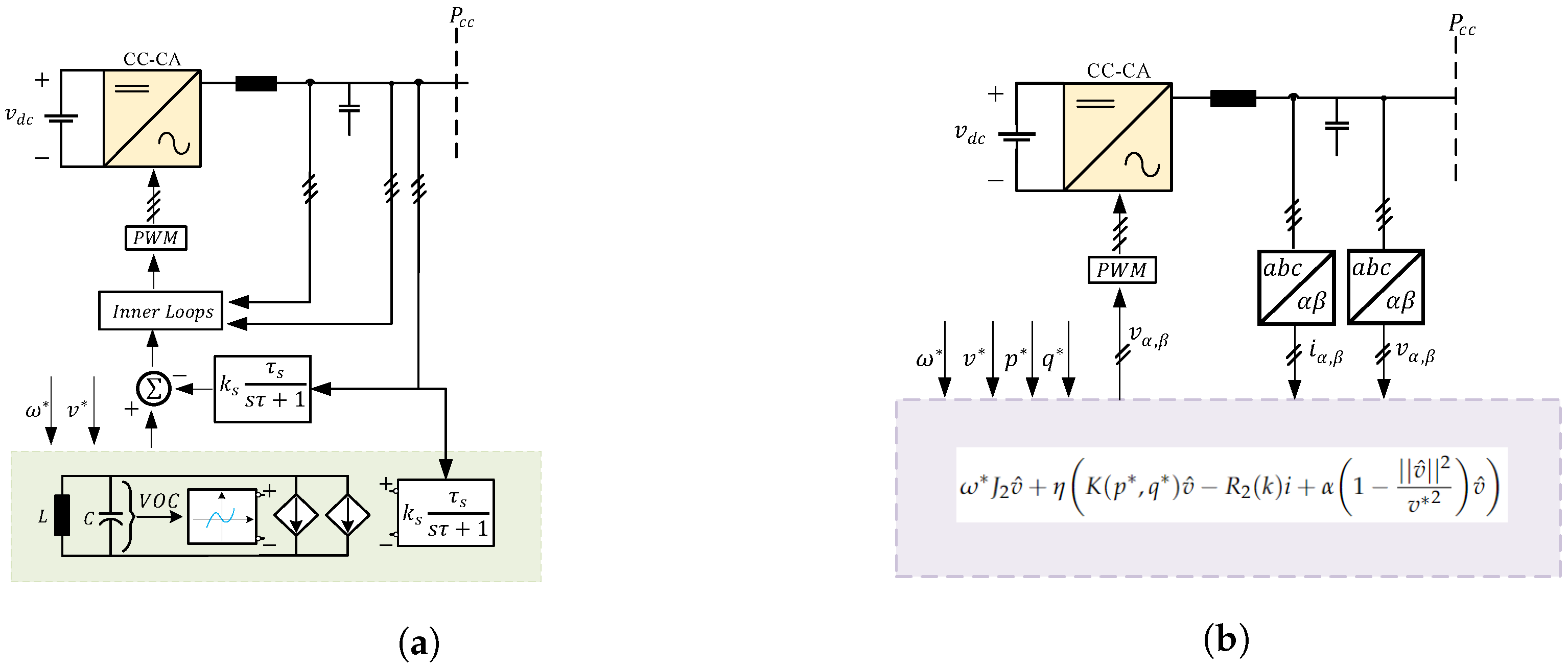
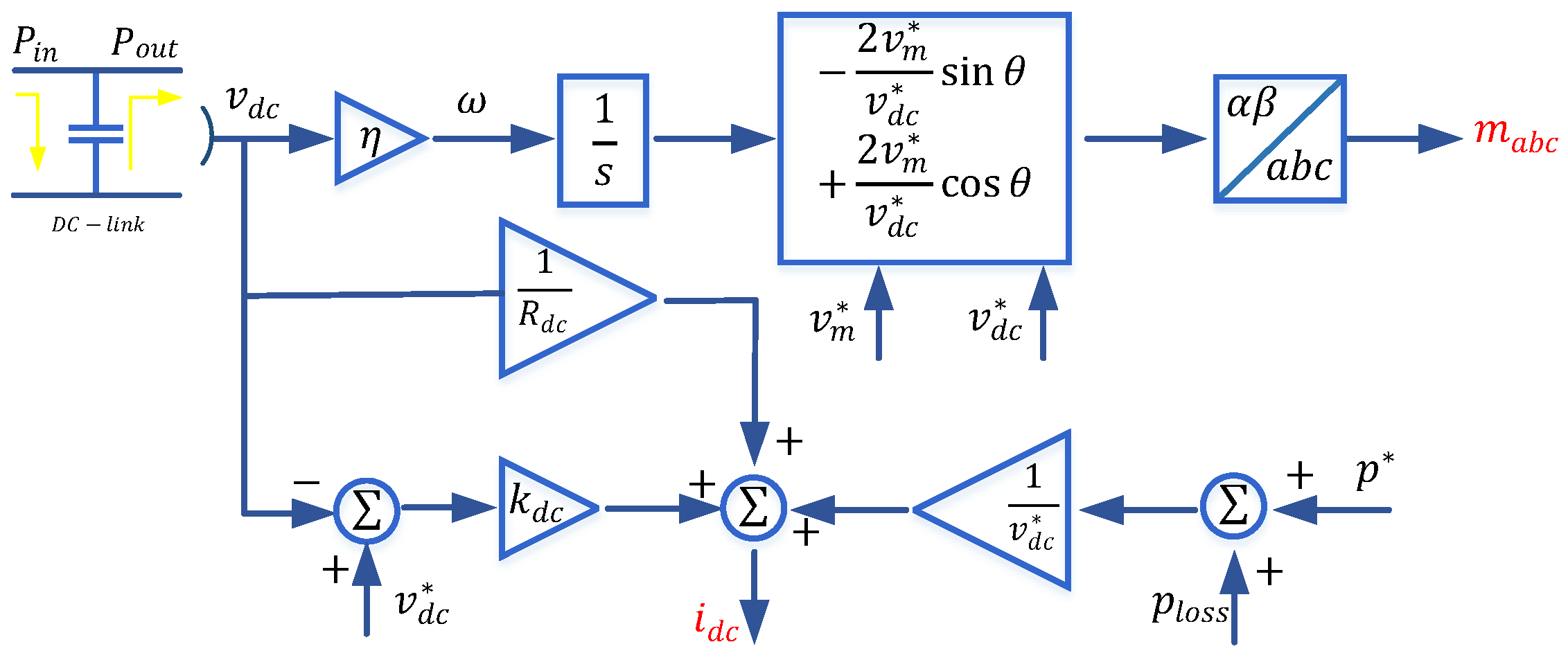
- Dispatchable Virtual Oscillator Control
- Machine Matching Control
- Sliding Mode Control
4.4. Synchronization System
4.4.1. Phase-Locked Loop
4.4.2. Frequency-Locked Loop
5. Island Detection
6. Gfm Inverters in the Power System
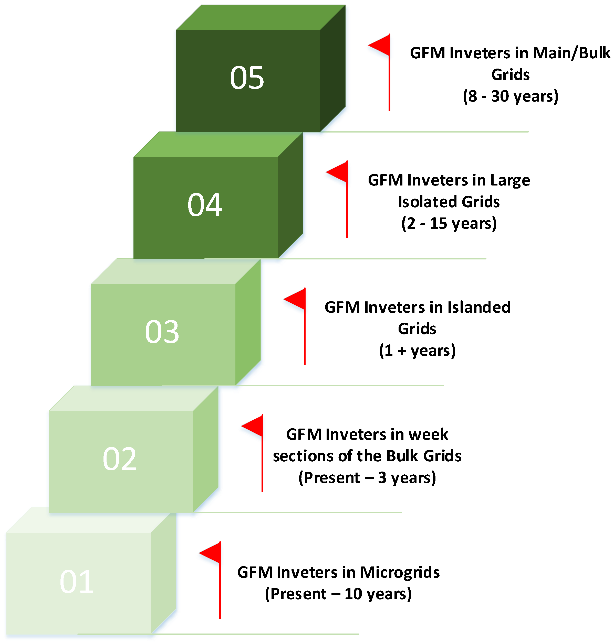
6.1. Sizing of GFM Inverter Reserve
6.2. Location of GFM Units
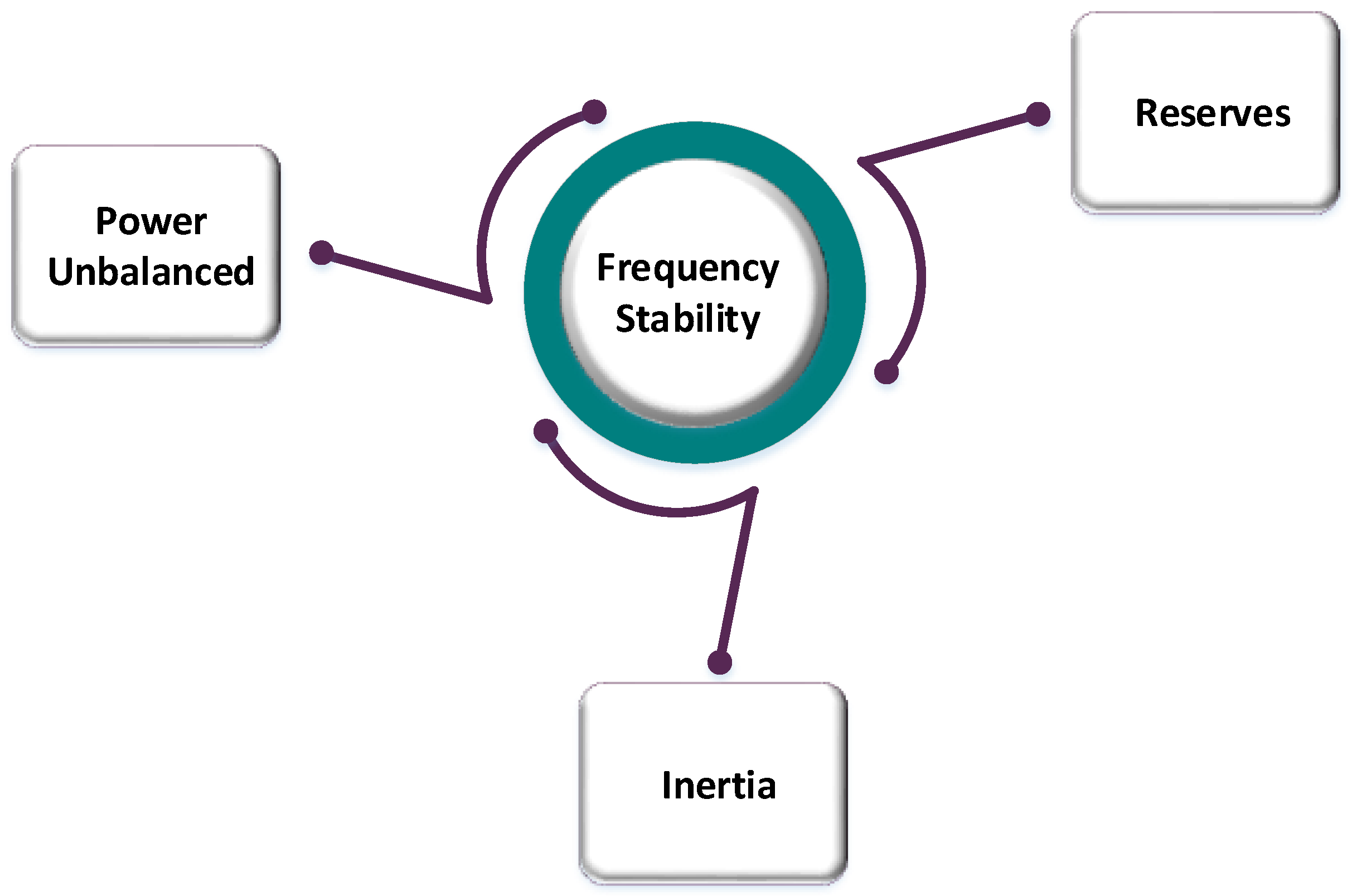
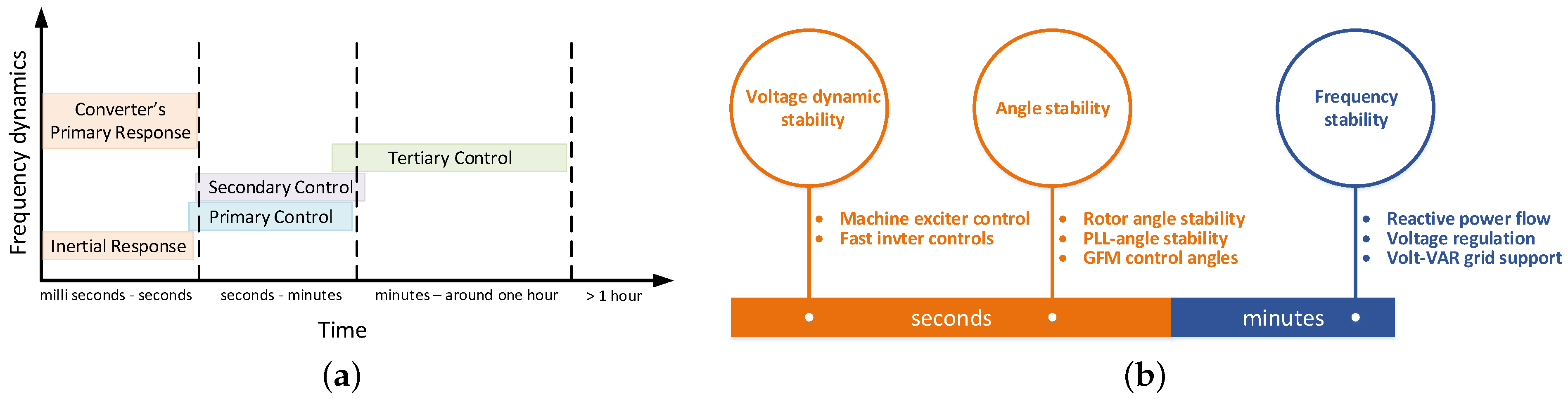
6.3. Power System Stability
6.4. Load Dynamics
7. Future Directions and Challenges for GFM
8. Discussion
9. Conclusions
Author Contributions
Funding
Institutional Review Board Statement
Informed Consent Statement
Data Availability Statement
Acknowledgments
Conflicts of Interest
References
- Arghir, C.; Jouini, T.; Dörfler, F. Grid-forming control for power converters based on matching of synchronous machines. Automatica 2018, 95, 273–282. [Google Scholar] [CrossRef] [Green Version]
- Tielens, P.; Hertem, D.V. The relevance of inertia in power systems. Renew. Sustain. Energy Rev. 2016, 55, 999–1009. [Google Scholar] [CrossRef]
- Milano, F.; Dörfler, F.; Hug, G.; Hill, D.J.; Verbič, G. Foundations and Challenges of Low-Inertia Systems (Invited Paper). In Proceedings of the 2018 Power Systems Computation Conference (PSCC), Dublin, Ireland, 11–15 June 2018; pp. 1–25. [Google Scholar] [CrossRef] [Green Version]
- Misyris, G.S.; Chatzivasileiadis, S.; Weckesser, T. Grid-forming converters: Sufficient conditions for RMS modeling. Electr. Power Syst. Res. 2021, 197, 107324. [Google Scholar] [CrossRef]
- Paiva, S.C.; de Araujo Ribeiro, R.L.; Alves, D.K.; Costa, F.B.; Rocha, T.D.O.A. A wavelet-based hybrid islanding detection system applied for distributed generators interconnected to AC microgrids. Int. J. Electr. Power Energy Syst. 2020, 121, 106032. [Google Scholar] [CrossRef]
- Antunes, H.M.A.; Silva, S.M.; Brandao, D.I.; Machado, A.A.P.; de Jesus Cardoso Filho, B. A new multifunctional converter based on a series compensator applied to AC microgrids. Int. J. Electr. Power Energy Syst. 2018, 102, 160–170. [Google Scholar] [CrossRef]
- Chhor, J.; Sourkounis, C. Optimal voltage control strategy for grid-feeding power converters in AC microgrids. Electr. Power Syst. Res. 2019, 176, 105945. [Google Scholar] [CrossRef]
- Patrao, I.; González-Medina, R.; Marzal, S.; Garcerá, G.; Figueres, E. Synchronization of power inverters in islanded microgrids using an FM-modulated signal. IEEE Trans. Smart Grid 2016, 8, 503–510. [Google Scholar] [CrossRef] [Green Version]
- Fogli, G.A.; de Almeida, P.M.; Barbosa, P.G. Modelling and control of an interface power converter for the operation of small diesel gen-sets in grid-connected and stand-alone modes. Electr. Power Syst. Res. 2017, 150, 177–187. [Google Scholar] [CrossRef]
- Wang, J.; Chang, N.C.P.; Feng, X.; Monti, A. Design of a generalized control algorithm for parallel inverters for smooth microgrid transition operation. IEEE Trans. Ind. Electron. 2015, 62, 4900–4914. [Google Scholar] [CrossRef]
- Mongrain, R.S.; Ayyanar, R. Control of nonideal grid-forming inverter in islanded microgrid with hierarchical control structure under unbalanced conditions. Int. J. Electr. Power Energy Syst. 2020, 119, 105890. [Google Scholar] [CrossRef]
- Guo, W.; Mu, L. Control principles of micro-source inverters used in microgrid. Prot. Control. Mod. Power Syst. 2016, 1, 5. [Google Scholar] [CrossRef]
- Li, Z.; Zang, C.; Zeng, P.; Yu, H.; Li, S.; Bian, J. Control of a Grid-Forming Inverter Based on Sliding-Mode and Mixed H2/H∞ Control. IEEE Trans. Ind. Electron. 2017, 64, 3862–3872. [Google Scholar] [CrossRef]
- Lliuyacc, R.; Mauricio, J.M.; Gomez-Exposito, A.; Savaghebi, M.; Guerrero, J.M. Grid-forming VSC control in four-wire systems with unbalanced nonlinear loads. Electr. Power Syst. Res. 2017, 152, 249–256. [Google Scholar] [CrossRef] [Green Version]
- Ojo, Y.; Watson, J.; Lestas, I. An Improved Control Scheme for Grid-forming Inverters. In Proceedings of the 2019 IEEE PES Innovative Smart Grid Technologies Europe (ISGT-Europe), Bucharest, Romania, 29 September–2 October 2019; pp. 1–5. [Google Scholar] [CrossRef]
- Lasseter, R.; Chen, Z.; Pattabiraman, D. Grid-Forming Inverters: A Critical Asset for the Power Grid. IEEE J. Emerg. Sel. Top. Power Electron. 2019, 8, 925–935. [Google Scholar] [CrossRef]
- Pattabiraman, D.; Lasseter, R.H.; Jahns, T.M. Comparison of Grid Following and Grid Forming Control for a High Inverter Penetration Power System. In Proceedings of the 2018 IEEE Power Energy Society General Meeting (PESGM), Portland, OR, USA, 5–10 August 2018; pp. 1–5. [Google Scholar] [CrossRef]
- Bouzid, A.M.; Guerrero, J.M.; Cheriti, A.; Bouhamida, M.; Sicard, P.; Benghanem, M. A survey on control of electric power distributed generation systems for microgrid applications. Renew. Sustain. Energy Rev. 2015, 44, 751–766. [Google Scholar] [CrossRef] [Green Version]
- Jouini, T.; Markovic, U.; Groß, D. Control and Operation of a Grid with 100% Converter-Based Devices—New Options for Existing System Services and Needs for New System Services; Deliverable (D3.3) Report, MIGRATE Project; European Union Horizons, 2018. [Google Scholar]
- Groß, D.; Colombino, M.; Brouillon, J.; Dörfler, F. The Effect of Transmission-Line Dynamics on Grid-Forming Dispatchable Virtual Oscillator Control. IEEE Trans. Control. Netw. Syst. 2019, 6, 1148–1160. [Google Scholar] [CrossRef] [Green Version]
- Buchhagen, C.; Rauscher, C.; Menze, A.; Jung, J. BorWin1-First Experiences with harmonic interactions in converter dominated grids. In Proceedings of the International ETG Congress 2015, Die Energiewende-Blueprints for the New Energy Age, Bonn, Germany, 17–18 November 2015; pp. 1–7. [Google Scholar]
- Hu, J.; Chi, Y.; Tian, X.; Zhou, Y.; He, W. A coordinated and steadily fault ride through strategy under short-circuit fault of the wind power grid connected system based on the grid-forming control. Energy Rep. 2022, 8, 333–341. [Google Scholar] [CrossRef]
- Aragon, D.; Unamuno, E.; Ceballos, S.; Barrena, J. Comparative small-signal evaluation of advanced grid-forming control techniques. Electr. Power Syst. Res. 2022, 211, 108154. [Google Scholar] [CrossRef]
- Musca, R.; Vasile, A.; Zizzo, G. Grid-forming converters. A critical review of pilot projects and demonstrators. Renew. Sustain. Energy Rev. 2022, 165, 112551. [Google Scholar] [CrossRef]
- Ojo, Y.; Benmiloud, M.; Lestas, I. Frequency and voltage control schemes for three-phase grid-forming inverters. IFAC-PapersOnLine 2020, 53, 13471–13476. [Google Scholar] [CrossRef]
- Tayyebi, A.; Groß, D.; Anta, A.; Kupzog, F.; Dörfler, F. Frequency stability of synchronous machines and grid-forming power converters. IEEE J. Emerg. Sel. Top. Power Electron. 2020, 8, 1004–1018. [Google Scholar] [CrossRef] [Green Version]
- Gouveia, J.; Moreira, C.; Lopes, J.P. Rule-based adaptive control strategy for grid-forming inverters in islanded power systems for improving frequency stability. Electr. Power Syst. Res. 2021, 197, 107339. [Google Scholar] [CrossRef]
- Ullah, S.; Khan, L.; Sami, I.; Ro, J.S. Voltage/Frequency Regulation with Optimal Load Dispatch in Microgrids using SMC based Distributed Cooperative Control. IEEE Access 2022, 10, 64873–64889. [Google Scholar] [CrossRef]
- Prevost, T.; Denis, G. WP3-Control and Operation of a Grid with 100% Converter-Based Devices. Eur. Horiz. 2020, 7923842. [Google Scholar]
- Khan, S.A.; Wang, M.; Su, W.; Liu, G.; Chaturvedi, S. Grid-Forming Converters for Stability Issues in Future Power Grids. Energies 2022, 15, 4937. [Google Scholar] [CrossRef]
- Lin, Y.; Johnson, B.B.; Dhople, S.V.; Bullo, F.; Chapman, P.; Purba, V.; Jafarpour, S.; Seo, G.S.; Villegas-Pico, H.; Ainsworth, N.; et al. Stabilizing the Power System in 2035 and Beyond: Evolving from Grid-Following to Grid-Forming Distributed Inverter Controllers (Final Technical Report); Technical Report; National Renewable Energy Lab. (NREL): Golden, CO, USA, 2021.
- Peacock, B. World’s Largest ‘Grid-Forming’ Battery to Begin Construction in Australia. Available online: https://www.pv-magazine.com/2021/08/10/worlds-largest-grid-forming-battery-to-begin-construction-in-australia/ (accessed on 1 January 2021).
- Roscoe, A.; Brogan, P.; Elliott, D.; Knueppel, T.; Gutierrez, I.; Campion, J.P.; Da Silva, R. Practical Experience of Operating a Grid Forming Wind Park and its Response to System Events. In Proceedings of the 18th Wind Integration Workshop, Dublin, Ireland, 14–18 October 2019. [Google Scholar]
- Nestor, S. Major Grid-Forming Battery Gains Momentum. Available online: https://www.energymagazine.com.au/major-grid-forming-battery-gains-momentum/ (accessed on 1 January 2022).
- Sales. SA Grid-Forming Project Setting Worldwide Example. Available online: https://ahlecsolar.com.au/2021/03/12/sa-grid-forming-project-setting-worldwide-example/ (accessed on 1 January 2021).
- Limited, A.E.M.O. Application of Advanced Grid-Scale Inverters in the NEM. Available online: https://aemo.com.au/-/media/files/initiatives/engineering-framework/2021/application-of-advanced-grid-scale-inverters-in-the-nem.pdf (accessed on 1 January 2021).
- Mohd, A.; Ortjohann, E.; Morton, D.; Omari, O. Review of control techniques for inverters parallel operation. Electr. Power Syst. Res. 2010, 80, 1477–1487. [Google Scholar] [CrossRef]
- Denis, G.; Prevost, T.; Panciatici, P.; Kestelyn, X.; Colas, F.; Guillaud, X. Review on potential strategies for transmission grid operations based on power electronics interfaced voltage sources. In Proceedings of the 2015 IEEE Power Energy Society General Meeting, Denver, CO, USA, 26–30 July 2015; pp. 1–5. [Google Scholar] [CrossRef]
- Andishgar, M.H.; Gholipour, E.; Hooshmand, R. An overview of control approaches of inverter-based microgrids in islanding mode of operation. Renew. Sustain. Energy Rev. 2017, 80, 1043–1060. [Google Scholar] [CrossRef]
- Miveh, M.R.; Rahmat, M.F.; Ghadimi, A.A.; Mustafa, M.W. Power Quality Improvement in Autonomous Microgrids Using Multi-functional Voltage Source Inverters: A Comprehensive Review. J. Power Electron. 2015, 15, 1054–1065. [Google Scholar] [CrossRef] [Green Version]
- Rocabert, J.; Luna, A.; Blaabjerg, F.; Rodríguez, P. Control of Power Converters in AC Microgrids. IEEE Trans. Power Electron. 2012, 27, 4734–4749. [Google Scholar] [CrossRef]
- Ali, Z.; Christofides, N.; Hadjidemetriou, L.; Kyriakides, E.; Yang, Y.; Blaabjerg, F. Three-phase phase-locked loop synchronization algorithms for grid-connected renewable energy systems: A review. Renew. Sustain. Energy Rev. 2018, 90, 434–452. [Google Scholar] [CrossRef] [Green Version]
- Qoria, T.; Prevost, T.; Denis, G.; Gruson, F.; Colas, F.; Guillaud, X. Power Converters Classification and Characterization in Power Transmission Systems. In Proceedings of the 2019 21st European Conference on Power Electronics and Applications (EPE ’19 ECCE Europe), Genova, Italy, 3–5 September 2019; pp. P.1–P.9. [Google Scholar] [CrossRef] [Green Version]
- Wai, R.; Lin, C.; Huang, Y.; Chang, Y. Design of High-Performance Stand-Alone and Grid-Connected Inverter for Distributed Generation Applications. IEEE Trans. Ind. Electron. 2013, 60, 1542–1555. [Google Scholar] [CrossRef]
- Arafat, M.N.; Palle, S.; Sozer, Y.; Husain, I. Transition Control Strategy Between Standalone and Grid-Connected Operations of Voltage-Source Inverters. IEEE Trans. Ind. Appl. 2012, 48, 1516–1525. [Google Scholar] [CrossRef]
- Azevedo, G.M.S.; Cavalcanti, M.C.; Neves, F.A.S.; Limongi, L.R.; Bradaschia, F. A control of microgrid power converter with smooth transient response during the change of connection mode. In Proceedings of the 2013 Brazilian Power Electronics Conference, Gramado, Brazil, 27–31 October 2013; pp. 1008–1015. [Google Scholar] [CrossRef]
- Arafat, M.N.; Elrayyah, A.; Sozer, Y. An Effective Smooth Transition Control Strategy Using Droop-Based Synchronization for Parallel Inverters. IEEE Trans. Ind. Appl. 2015, 51, 2443–2454. [Google Scholar] [CrossRef]
- Zhong, Q.; Nguyen, P.; Ma, Z.; Sheng, W. Self-Synchronized Synchronverters: Inverters without a Dedicated Synchronization Unit. IEEE Trans. Power Electron. 2014, 29, 617–630. [Google Scholar] [CrossRef]
- Guerrero, J.M.; Vasquez, J.C.; Matas, J.; de Vicuna, L.G.; Castilla, M. Hierarchical Control of Droop-Controlled AC and DC Microgrids—A General Approach toward Standardization. IEEE Trans. Ind. Electron. 2011, 58, 158–172. [Google Scholar] [CrossRef]
- Babu, N.R. Smart Grid Systems: Modeling and Control, 1st ed.; Apple Academic Press: Burlington, MA, USA, 2018. [Google Scholar]
- Antunes, H.; Silva, S.; Filho, B.; Ferreira, R.; Brandao, D.I. A New Configuration for a Grid Forming Converter in AC Islanded Microgrid. In Proceedings of the PCIM Europe 2017; International Exhibition and Conference for Power Electronics, Intelligent Motion, Renewable Energy and Energy Management, Nuremberg, Germany, 16–18 May 2017; pp. 1–8. [Google Scholar]
- Hazra, S.; De, A.; Cheng, L.; Palmour, J.; Schupbach, M.; Hull, B.A.; Allen, S.; Bhattacharya, S. High Switching Performance of 1700-V, 50-A SiC Power MOSFET Over Si IGBT/BiMOSFET for Advanced Power Conversion Applications. IEEE Trans. Power Electron. 2016, 31, 4742–4754. [Google Scholar] [CrossRef]
- Sher, H.A.; Rizvi, A.A.; Addoweesh, K.E.; Al-Haddad, K. A single-stage stand-alone photovoltaic energy system with high tracking efficiency. IEEE Trans. Sustain. Energy 2016, 8, 755–762. [Google Scholar] [CrossRef]
- Sher, H.A.; Addoweesh, K.E.; Al-Haddad, K. An efficient and cost-effective hybrid MPPT method for a photovoltaic flyback microinverter. IEEE Trans. Sustain. Energy 2017, 9, 1137–1144. [Google Scholar] [CrossRef]
- Yazdani, A.; Iravani, R. Voltage-Sourced Converters in Power Systems: Modeling, Control, and Applications, 1st ed.; John Wiley & Sons: Hoboken, NJ, USA, 2010. [Google Scholar]
- Bahrani, B.; Rufer, A. A cascade voltage controller for three-phase islanded microgrids. In Proceedings of the 2013 IEEE Power & Energy Society General Meeting, Vancouver, BC, Canada, 21–25 July 2013; pp. 1–6. [Google Scholar]
- De Souza, I.D.; de Almeida, P.M.; Barbosa, P.G.; Duque, C.A.; Ribeiro, P.F. Digital single voltage loop control of a VSI with LC output filter. Sustain. Energy Grids Networks 2018, 16, 145–155. [Google Scholar] [CrossRef]
- Serban, I.; Petrea Ion, C. Microgrid control based on a grid-forming inverter operating as virtual synchronous generator with enhanced dynamic response capability. Int. J. Electr. Power Energy Syst. 2017, 89, 94–105. [Google Scholar] [CrossRef]
- Antunes, H.M.A.; Silva, S.M.; Brandao, D.I.; Machado, A.A.P.; Ferreira, R.V. A fault-tolerant grid-forming converter applied to AC microgrids. Int. J. Electr. Power Energy Syst. 2020, 121, 106072. [Google Scholar] [CrossRef]
- Gonzatti, R.B.; Ferreira, S.C.; da Silva, C.H.; Pereira, R.R.; da Silva, L.E.B.; Lambert-Torres, G.; Pereira, R. Implementation of a grid-forming converter based on modified synchronous reference frame. In Proceedings of the IECON 2014-40th Annual Conference of the IEEE Industrial Electronics Society, Dallas, TX, USA, 29 October–1 November 2014; pp. 2116–2121. [Google Scholar]
- Peña, J.C.; Melo, G.; Canesin, C.A.; Sampaio, L.P. Robust control of a single-phase VSI with LCL filter for grid-tie and islanded operation modes applied to PV distributed generation in microgrids environment. In Proceedings of the 2014 IEEE Energy Conversion Congress and Exposition (ECCE), Pittsburgh, PA, USA, 14–18 September 2014; pp. 785–792. [Google Scholar]
- Ninad, N.A.; Lopes, L.A. Unbalanced operation of per-phase vector controlled four-leg grid forming inverter for stand-alone hybrid systems. In Proceedings of the IECON 2012-38th Annual Conference on IEEE Industrial Electronics Society, Montreal, QC, Canada, 25–28 October 2012; pp. 3500–3505. [Google Scholar]
- Miveh, M.R.; Rahmat, M.F.; Ghadimi, A.A.; Mustafa, M.W. Control techniques for three-phase four-leg voltage source inverters in autonomous microgrids: A review. Renew. Sustain. Energy Rev. 2016, 54, 1592–1610. [Google Scholar] [CrossRef]
- Gervasio, F.A.; Bueno, E.; Mastromauro, R.A.; Liserre, M.; Stasi, S. Voltage control of microgrid systems based on 3L-NPC inverters with LCL-filter in islanding operation. In Proceedings of the 2015 International Conference on Renewable Energy Research and Applications (ICRERA), Palermo, Italy, 22–25 November 2015; pp. 827–832. [Google Scholar] [CrossRef]
- Singh, M.; Lopes, L.A.; Ninad, N.A. Grid forming Battery Energy Storage System (BESS) for a highly unbalanced hybrid mini-grid. Electr. Power Syst. Res. 2015, 127, 126–133. [Google Scholar] [CrossRef]
- Gkountaras, A.; Dieckerhoff, S.; Sezi, T. Evaluation of current limiting methods for grid forming inverters in medium voltage microgrids. In Proceedings of the 2015 IEEE Energy Conversion Congress and Exposition (ECCE), Montreal, QC, Canada, 20–24 September 2015; pp. 1223–1230. [Google Scholar] [CrossRef]
- Rokrok, E.; Qoria, T.; Bruyere, A.; Francois, B.; Zhang, H.; Belhaouane, M.; Guillaud, X. Impact of grid-forming control on the internal energy of a modular multilevel converter. In Proceedings of the 2020 22nd European Conference on Power Electronics and Applications (EPE’20 ECCE Europe), Lyon, France, 7–11 September 2020; pp. 1–10. [Google Scholar]
- Jayalath, S.; Hanif, M. Generalized LCL-Filter Design Algorithm for Grid-Connected Voltage-Source Inverter. IEEE Trans. Ind. Electron. 2017, 64, 1905–1915. [Google Scholar] [CrossRef]
- Li, S.; Fu, X.; Ramezani, M.; Sun, Y.; Won, H. A novel direct-current vector control technique for single-phase inverter with L, LC and LCL filters. Electr. Power Syst. Res. 2015, 125, 235–244. [Google Scholar] [CrossRef]
- Jalili, K.; Bernet, S. Design of LCL Filters of Active-Front-End Two-Level Voltage-Source Converters. IEEE Trans. Ind. Electron. 2009, 56, 1674–1689. [Google Scholar] [CrossRef]
- Silva, S.M.; Filho, B.J.C. Component-minimized voltage sag compensators. In Proceedings of the Conference Record of the 2002 IEEE Industry Applications Conference. 37th IAS Annual Meeting (Cat. No. 02CH37344), Pittsburgh, PA, USA, 13–18 October 2002; Volume 2, pp. 883–889. [Google Scholar]
- Kim, J.; Choi, J.; Hong, H. Output LC filter design of voltage source inverter considering the performance of controller. In Proceedings of the 2000 International Conference on Power System Technology Proceedings (Cat. No. 00EX409), Perth, Australia, 4–7 December 2000; Volume 3, pp. 1659–1664. [Google Scholar]
- Moon, H.J.; Chang, J.W.; Lee, S.Y.; Moon, S.I. Autonomous active power management in isolated microgrid based on proportional and droop control. Energy Procedia 2018, 153, 48–55. [Google Scholar] [CrossRef]
- Ramezani, M.; Li, S.; Sun, Y. DQ-reference-frame based impedance and power control design of islanded parallel voltage source converters for integration of distributed energy resources. Electr. Power Syst. Res. 2019, 168, 67–80. [Google Scholar] [CrossRef]
- Wang, X.; Blaabjerg, F.; Chen, Z. Autonomous Control of Inverter-Interfaced Distributed Generation Units for Harmonic Current Filtering and Resonance Damping in an Islanded Microgrid. IEEE Trans. Ind. Appl. 2014, 50, 452–461. [Google Scholar] [CrossRef]
- Reznik, A.; Simões, M.G.; Al-Durra, A.; Muyeen, S. LCL filter design and performance analysis for small wind turbine systems. In Proceedings of the 2012 IEEE Power Electronics and Machines in Wind Applications, Denver, Colorado, 16–18 July 2012; pp. 1–7. [Google Scholar]
- Rasekh, N.; Hosseinpour, M. LCL filter design and robust converter side current feedback control for grid-connected Proton Exchange Membrane Fuel Cell system. Int. J. Hydrog. Energy 2020, 45, 13055–13067. [Google Scholar] [CrossRef]
- Mahlooji, M.H.; Mohammadi, H.R.; Rahimi, M. A review on modeling and control of grid-connected photovoltaic inverters with LCL filter. Renew. Sustain. Energy Rev. 2018, 81, 563–578. [Google Scholar] [CrossRef]
- Guerrero, J.M.; de Vicuna, L.G.; Matas, J.; Castilla, M.; Miret, J. Output impedance design of parallel-connected UPS inverters with wireless load-sharing control. IEEE Trans. Ind. Electron. 2005, 52, 1126–1135. [Google Scholar] [CrossRef]
- Micallef, A.; Apap, M.; Spiteri-Staines, C.; Guerrero, J.M.; Vasquez, J.C. Reactive Power Sharing and Voltage Harmonic Distortion Compensation of Droop Controlled Single Phase Islanded Microgrids. IEEE Trans. Smart Grid 2014, 5, 1149–1158. [Google Scholar] [CrossRef]
- Yao, W.; Chen, M.; Matas, J.; Guerrero, J.M.; Qian, Z.M. Design and analysis of the droop control method for parallel inverters considering the impact of the complex impedance on the power sharing. IEEE Trans. Ind. Electron. 2010, 58, 576–588. [Google Scholar] [CrossRef]
- Tao, Y.; Liu, Q.; Deng, Y.; Liu, X.; He, X. Analysis and mitigation of inverter output impedance impacts for distributed energy resource interface. IEEE Trans. Power Electron. 2014, 30, 3563–3576. [Google Scholar] [CrossRef]
- Hossain, M.A.; Pota, H.R.; Issa, W.; Hossain, M.J. Overview of AC microgrid controls with inverter-interfaced generations. Energies 2017, 10, 1300. [Google Scholar] [CrossRef]
- Ishaq, S.; Khan, I.; Rahman, S.; Hussain, T.; Iqbal, A.; Elavarasan, R.M. A review on recent developments in control and optimization of micro grids. Energy Rep. 2022, 8, 4085–4103. [Google Scholar] [CrossRef]
- Ullah, S.; Khan, L.; Sami, I.; Ullah, N. Consensus-based delay-tolerant distributed secondary control strategy for droop controlled AC microgrids. IEEE Access 2021, 9, 6033–6049. [Google Scholar] [CrossRef]
- Qoria, T.; Gruson, F.; Colas, F.; Guillaud, X.; Debry, M.S.; Prevost, T. Tuning of cascaded controllers for robust grid-forming Voltage Source Converter. In Proceedings of the 2018 Power Systems Computation Conference (PSCC), Dublin, Ireland, 11–15 June 2018; pp. 1–7. [Google Scholar]
- Tayyebi, A.; Groß, D.; Anta, A.; Kupzog, F.; Dörfler, F. Interactions of grid-forming power converters and synchronous machines—A comparative study. arXiv 2019, arXiv:1902.10750. [Google Scholar]
- Qoria, T.; Li, C.; Oue, K.; Gruson, F.; Colas, F.; Guillaud, X. Direct AC voltage control for grid-forming inverters. J. Power Electron. 2020, 20, 198–211. [Google Scholar] [CrossRef]
- Nisha, G.; Ushakumari, S.; Lakaparampil, Z. Online Harmonic Elimination of SVPWM for Three Phase Inverter and a Systematic Method for Practical Implementation. IAENG Int. J. Comput. Sci. 2012, 39, 220–230. [Google Scholar]
- Bottrell, N.; Green, T.C. Comparison of Current-Limiting Strategies During Fault Ride-Through of Inverters to Prevent Latch-Up and Wind-Up. IEEE Trans. Power Electron. 2014, 29, 3786–3797. [Google Scholar] [CrossRef] [Green Version]
- Camacho, A.; Castilla, M.; Miret, J.; Vasquez, J.C.; Alarcon-Gallo, E. Flexible Voltage Support Control for Three-Phase Distributed Generation Inverters Under Grid Fault. IEEE Trans. Ind. Electron. 2013, 60, 1429–1441. [Google Scholar] [CrossRef]
- Buraimoh, E.; Davidson, I.E.; Martinez-Rodrigo, F. Fault Ride-Through Enhancement of Grid Supporting Inverter-Based Microgrid Using Delayed Signal Cancellation Algorithm Secondary Control. Energies 2019, 12, 3994. [Google Scholar] [CrossRef] [Green Version]
- Plet, C.A.; Brucoli, M.; McDonald, J.D.F.; Green, T.C. Fault models of inverter-interfaced distributed generators: Experimental verification and application to fault analysis. In Proceedings of the 2011 IEEE Power and Energy Society General Meeting, Detroit, MI, USA, 24–29 July 2011; pp. 1–8. [Google Scholar] [CrossRef] [Green Version]
- Bloemink, J.M.; Iravani, M.R. Control of a Multiple Source Microgrid with Built-in Islanding Detection and Current Limiting. IEEE Trans. Power Deliv. 2012, 27, 2122–2132. [Google Scholar] [CrossRef]
- Baghaee, H.R.; Mirsalim, M.; Gharehpetian, G.B.; Talebi, H.A. A new current limiting strategy and fault model to improve fault ride-through capability of inverter interfaced DERs in autonomous microgrids. Sustain. Energy Technol. Assessments 2017, 24, 71–81. [Google Scholar] [CrossRef]
- Paquette, A.D.; Divan, D.M. Virtual Impedance Current Limiting for Inverters in Microgrids with Synchronous Generators. IEEE Trans. Ind. Appl. 2015, 51, 1630–1638. [Google Scholar] [CrossRef]
- Lu, X.; Wang, J.; Guerrero, J.M.; Zhao, D. Virtual-Impedance-Based Fault Current Limiters for Inverter Dominated AC Microgrids. IEEE Trans. Smart Grid 2018, 9, 1599–1612. [Google Scholar] [CrossRef] [Green Version]
- Gouveia, J.; Moreira, C.L.; Lopes, J.A.P. Grid-Forming Inverters Sizing in Islanded Power Systems—A stability perspective. In Proceedings of the 2019 International Conference on Smart Energy Systems and Technologies (SEST), Porto, Portugal, 9–11 September 2019; pp. 1–6. [Google Scholar]
- Baimel, D.; Belikov, J.; Guerrero, J.M.; Levron, Y. Dynamic Modeling of Networks, Microgrids, and Renewable Sources in the dq0 Reference Frame: A Survey. IEEE Access 2017, 5, 21323–21335. [Google Scholar] [CrossRef]
- O’Rourke, C.J.; Qasim, M.M.; Overlin, M.R.; Kirtley, J.L. A Geometric Interpretation of Reference Frames and Transformations: dq0, Clarke, and Park. IEEE Trans. Energy Convers. 2019, 34, 2070–2083. [Google Scholar] [CrossRef] [Green Version]
- Jain, M.; Gupta, S.; Masand, D.; Agnihotri, G.; Jain, S. Real-time implementation of islanded microgrid for remote areas. J. Control. Sci. Eng. 2016, 2016, 5710950. [Google Scholar] [CrossRef]
- Cárdenas, R.; Peña, R.; Clare, J.; Wheeler, P.; Zanchetta, P. A repetitive control system for four-leg matrix converters feeding non-linear loads. Electr. Power Syst. Res. 2013, 104, 18–27. [Google Scholar] [CrossRef]
- Hosseinpour, M.; Mohamadian, M.; Yazdian Varjani, A. Design and analysis of the droop-controlled parallel four-leg inverters to share unbalanced and nonlinear loads. J. Nonlinear Syst. Electr. Eng. 2014, 1, 76–92. [Google Scholar]
- Mattavelli, P. An improved deadbeat control for UPS using disturbance observers. IEEE Trans. Ind. Electron. 2005, 52, 206–212. [Google Scholar] [CrossRef]
- Kojima, M.; Hirabayashi, K.; Kawabata, Y.; Ejiogu, E.C.; Kawabata, T. Novel vector control system using deadbeat-controlled PWM inverter with output LC filter. IEEE Trans. Ind. Appl. 2004, 40, 162–169. [Google Scholar] [CrossRef]
- Cortés, P.; Ortiz, G.; Yuz, J.I.; Rodríguez, J.; Vazquez, S.; Franquelo, L.G. Model predictive control of an inverter with output LC filter for UPS applications. IEEE Trans. Ind. Electron. 2009, 56, 1875–1883. [Google Scholar] [CrossRef]
- Yang, L.Y.; Liu, J.H.; Wang, C.L.; Du, G.F. Sliding mode control of three-phase four-leg inverters via state feedback. J. Power Electron. 2014, 14, 1028–1037. [Google Scholar] [CrossRef] [Green Version]
- Zhang, X.; Wang, J.; Li, C. Three-phase four-leg inverter based on voltage hysteresis control. In Proceedings of the 2010 International Conference on Electrical and Control Engineering, Wuhan, China, 25–27 June 2010; pp. 4482–4485. [Google Scholar]
- Vechiu, I.; Camblong, H.; Tapia, G.; Dakyo, B.; Curea, O. Control of four leg inverter for hybrid power system applications with unbalanced load. Energy Convers. Manag. 2007, 48, 2119–2128. [Google Scholar] [CrossRef]
- Yao, Z.; Xiao, L.; Yan, Y. Seamless Transfer of Single-Phase Grid-Interactive Inverters Between Grid-Connected and Stand-Alone Modes. IEEE Trans. Power Electron. 2010, 25, 1597–1603. [Google Scholar] [CrossRef]
- Qoria, T.; Li, C.; Oue, K.; Gruson, F.; Colas, F.; Guillaud, X.; Prévost, T. Tuning of AC voltage-controlled VSC based Linear Quadratic Regulation. In Proceedings of the 2019 IEEE Milan PowerTech, Milan, Italy, 23–27 June 2019; pp. 1–6. [Google Scholar]
- Nazifi, H.; Radan, A. Current control assisted and non-ideal proportional-resonant voltage controller for four-leg three-phase inverters with time-variant loads. In Proceedings of the 4th Annual International Power Electronics, Drive Systems and Technologies Conference, Tehran, Iran, 13–14 February 2013; pp. 355–360. [Google Scholar]
- Rokrok, E.; HAMEDANI, G.M. Comprehensive control scheme for an inverter-based distributed generation unit. Iran. J. Sci. Technol. Trans. B Eng. 2009, 33, 477–490. [Google Scholar]
- Olivares, D.E.; Mehrizi-Sani, A.; Etemadi, A.H.; Cañizares, C.A.; Iravani, R.; Kazerani, M.; Hajimiragha, A.H.; Gomis-Bellmunt, O.; Saeedifard, M.; Palma-Behnke, R.; et al. Trends in microgrid control. IEEE Trans. Smart Grid 2014, 5, 1905–1919. [Google Scholar] [CrossRef]
- Han, H.; Hou, X.; Yang, J.; Wu, J.; Su, M.; Guerrero, J.M. Review of Power Sharing Control Strategies for Islanding Operation of AC Microgrids. IEEE Trans. Smart Grid 2016, 7, 200–215. [Google Scholar] [CrossRef] [Green Version]
- Barklund, E.; Pogaku, N.; Prodanovic, M.; Hernandez-Aramburo, C.; Green, T.C. Energy Management in Autonomous Microgrid Using Stability-Constrained Droop Control of Inverters. IEEE Trans. Power Electron. 2008, 23, 2346–2352. [Google Scholar] [CrossRef] [Green Version]
- Aboushal, M.; Moustafa, M.M.Z. A new unified control strategy for inverter-based micro-grid using hybrid droop scheme. Alex. Eng. J. 2019, 58, 1229–1245. [Google Scholar] [CrossRef]
- D’Arco, S.; Suul, J.A. Virtual synchronous machines—Classification of implementations and analysis of equivalence to droop controllers for microgrids. In Proceedings of the 2013 IEEE Grenoble Conference, Grenoble, France, 18–22 March 2013; pp. 1–7. [Google Scholar] [CrossRef]
- D’Arco, S.; Suul, J.A.; Fosso, O.B. A Virtual Synchronous Machine implementation for distributed control of power converters in SmartGrids. Electr. Power Syst. Res. 2015, 122, 180–197. [Google Scholar] [CrossRef]
- Bevrani, H.; Ise, T.; Miura, Y. Virtual synchronous generators: A survey and new perspectives. Int. J. Electr. Power Energy Syst. 2014, 54, 244–254. [Google Scholar] [CrossRef]
- Wu, W.; Chen, Y.; Luo, A.; Zhou, L.; Zhou, X.; Yang, L.; Dong, Y.; Guerrero, J.M. A Virtual Inertia Control Strategy for DC Microgrids Analogized with Virtual Synchronous Machines. IEEE Trans. Ind. Electron. 2017, 64, 6005–6016. [Google Scholar] [CrossRef] [Green Version]
- Johnson, B.B.; Dhople, S.V.; Hamadeh, A.O.; Krein, P.T. Synchronization of Parallel Single-Phase Inverters with Virtual Oscillator Control. IEEE Trans. Power Electron. 2014, 29, 6124–6138. [Google Scholar] [CrossRef]
- Colombino, M.; Groß, D.; Brouillon, J.S.; Dörfler, F. Global phase and magnitude synchronization of coupled oscillators with application to the control of grid-forming power inverters. IEEE Trans. Autom. Control 2019, 64, 4496–4511. [Google Scholar] [CrossRef] [Green Version]
- Lidula, N.; Rajapakse, A. Microgrids research: A review of experimental microgrids and test systems. Renew. Sustain. Energy Rev. 2011, 15, 186–202. [Google Scholar] [CrossRef]
- Pogaku, N.; Prodanovic, M.; Green, T.C. Modeling, Analysis and Testing of Autonomous Operation of an Inverter-Based Microgrid. IEEE Trans. Power Electron. 2007, 22, 613–625. [Google Scholar] [CrossRef] [Green Version]
- Khadem, S.K.; Basu, M.; Conlon, M.F. Parallel operation of inverters and active power filters in distributed generation system—A review. Renew. Sustain. Energy Rev. 2011, 15, 5155–5168. [Google Scholar] [CrossRef] [Green Version]
- Vasquez, J.C.; Guerrero, J.M.; Miret, J.; Castilla, M.; De Vicuna, L.G. Hierarchical control of intelligent microgrids. IEEE Ind. Electron. Mag. 2010, 4, 23–29. [Google Scholar] [CrossRef]
- Tayab, U.B.; Roslan, M.A.B.; Hwai, L.J.; Kashif, M. A review of droop control techniques for microgrid. Renew. Sustain. Energy Rev. 2017, 76, 717–727. [Google Scholar] [CrossRef]
- Planas, E.; de Muro, A.G.; Andreu, J.; Kortabarria, I.; de Alegría, I.M. General aspects, hierarchical controls and droop methods in microgrids: A review. Renew. Sustain. Energy Rev. 2013, 17, 147–159. [Google Scholar] [CrossRef]
- Majumder, R.; Chaudhuri, B.; Ghosh, A.; Majumder, R.; Ledwich, G.; Zare, F. Improvement of Stability and Load Sharing in an Autonomous Microgrid Using Supplementary Droop Control Loop. IEEE Trans. Power Syst. 2010, 25, 796–808. [Google Scholar] [CrossRef] [Green Version]
- Kim, J.W.; Choi, H.S.; Cho, B.H. A novel droop method for converter parallel operation. IEEE Trans. Power Electron. 2002, 17, 25–32. [Google Scholar] [CrossRef]
- Hu, J.; Zhu, J.; Dorrell, D.G.; Guerrero, J.M. Virtual Flux Droop Method—A New Control Strategy of Inverters in Microgrids. IEEE Trans. Power Electron. 2014, 29, 4704–4711. [Google Scholar] [CrossRef] [Green Version]
- Vasquez, J.C.; Guerrero, J.M.; Luna, A.; Rodriguez, P.; Teodorescu, R. Adaptive Droop Control Applied to Voltage-Source Inverters Operating in Grid-Connected and Islanded Modes. IEEE Trans. Ind. Electron. 2009, 56, 4088–4096. [Google Scholar] [CrossRef]
- Rokrok, E.; Golshan, M.E.H. Adaptive voltage droop scheme for voltage source converters in an islanded multibus microgrid. IET Gener. Transm. D 2010, 4, 562–578. [Google Scholar] [CrossRef] [Green Version]
- Li, Y.W.; Kao, C. An Accurate Power Control Strategy for Power-Electronics-Interfaced Distributed Generation Units Operating in a Low-Voltage Multibus Microgrid. IEEE Trans. Power Electron. 2009, 24, 2977–2988. [Google Scholar] [CrossRef]
- Savaghebi, M.; Jalilian, A.; Vasquez, J.C.; Guerrero, J.M. Autonomous Voltage Unbalance Compensation in an Islanded Droop-Controlled Microgrid. IEEE Trans. Ind. Electron. 2013, 60, 1390–1402. [Google Scholar] [CrossRef] [Green Version]
- Liu, Q.; Tao, Y.; Liu, X.; Deng, Y.; He, X. Voltage unbalance and harmonics compensation for islanded microgrid inverters. IET Power Electron. 2014, 7, 1055–1063. [Google Scholar] [CrossRef] [Green Version]
- Sao, C.K.; Lehn, P.W. Autonomous load sharing of voltage source converters. IEEE Trans. Power Deliv. 2005, 20, 1009–1016. [Google Scholar] [CrossRef]
- Mohamed, Y.A.I.; El-Saadany, E.F. Adaptive Decentralized Droop Controller to Preserve Power Sharing Stability of Paralleled Inverters in Distributed Generation Microgrids. IEEE Trans. Power Electron. 2008, 23, 2806–2816. [Google Scholar] [CrossRef]
- Machowski, J.; Bialek, J.W.; Bumby, J.R. Power System Dynamics: Stability and Control, 2nd ed.; Wiley: Chichester, UK, 2008; Chapter 5. [Google Scholar]
- Zhong, Q.C.; Weiss, G. Synchronverters: Inverters that mimic synchronous generators. IEEE Trans. Ind. Electron. 2010, 58, 1259–1267. [Google Scholar] [CrossRef]
- Belila, A.; Amirat, Y.; Benbouzid, M.; Berkouk, E.M.; Yao, G. Virtual synchronous generators for voltage synchronization of a hybrid PV-diesel power system. Int. J. Electr. Power Energy Syst. 2020, 117, 105677. [Google Scholar] [CrossRef]
- Fitzgerald, A.E.; Kingsley, C.; Umans, S.D.; James, B. Electric Machinery, 6th ed.; McGraw-Hill: New York, NY, USA, 2003. [Google Scholar]
- D’Arco, S.; Suul, J.A. Equivalence of Virtual Synchronous Machines and Frequency-Droops for Converter-Based MicroGrids. IEEE Trans. Smart Grid 2014, 5, 394–395. [Google Scholar] [CrossRef]
- Ofir, R.; Markovic, U.; Aristidou, P.; Hug, G. Droop vs. virtual inertia: Comparison from the perspective of converter operation mode. In Proceedings of the 2018 IEEE International Energy Conference (ENERGYCON), Limassol, Cyprus, 3–7 June 2018; pp. 1–6. [Google Scholar]
- Liu, J.; Miura, Y.; Ise, T. Comparison of Dynamic Characteristics Between Virtual Synchronous Generator and Droop Control in Inverter-Based Distributed Generators. IEEE Trans. Power Electron. 2016, 31, 3600–3611. [Google Scholar] [CrossRef]
- Seo, G.; Colombino, M.; Subotic, I.; Johnson, B.; Groß, D.; Dörfler, F. Dispatchable Virtual Oscillator Control for Decentralized Inverter-dominated Power Systems: Analysis and Experiments. In Proceedings of the 2019 IEEE Applied Power Electronics Conference and Exposition (APEC), Anaheim, CA, USA, 17–21 March 2019; pp. 561–566. [Google Scholar] [CrossRef] [Green Version]
- Awal, M.A.; Yu, H.; Tu, H.; Lukic, S.M.; Husain, I. Hierarchical Control for Virtual Oscillator Based Grid-Connected and Islanded Microgrids. IEEE Trans. Power Electron. 2020, 35, 988–1001. [Google Scholar] [CrossRef]
- Awal, M.A.; Yu, H.; Husain, I.; Yu, W.; Lukic, S. Selective Harmonic Current Rejection for Virtual Oscillator Controlled Grid-Forming Voltage Source Converters. IEEE Trans. Power Electron. 2020, 35, 8805–8818. [Google Scholar] [CrossRef]
- Johnson, B.; Rodriguez, M.; Sinha, M.; Dhople, S. Comparison of virtual oscillator and droop control. In Proceedings of the 2017 IEEE 18th Workshop on Control and Modeling for Power Electronics (COMPEL), Stanford, CA, USA, 9–12 July 2017; pp. 1–6. [Google Scholar] [CrossRef]
- Shi, Z.; Li, J.; Nurdin, H.I.; Fletcher, J.E. Comparison of Virtual Oscillator and Droop Controlled Islanded Three-Phase Microgrids. IEEE Trans. Energy Convers. 2019, 34, 1769–1780. [Google Scholar] [CrossRef]
- Johnson, B.B.; Sinha, M.; Ainsworth, N.G.; Dörfler, F.; Dhople, S.V. Synthesizing Virtual Oscillators to Control Islanded Inverters. IEEE Trans. Power Electron. 2016, 31, 6002–6015. [Google Scholar] [CrossRef]
- Dhople, S.V.; Johnson, B.B.; Hamadeh, A.O. Virtual Oscillator Control for voltage source inverters. In Proceedings of the 2013 51st Annual Allerton Conference on Communication, Control, and Computing (Allerton), Monticello, IL, USA, 2–4 October 2013; pp. 1359–1363. [Google Scholar] [CrossRef]
- Azizi Aghdam, S.; Agamy, M. Virtual oscillator-based methods for grid-forming inverter control: A review. IET Renew. Power Gener. 2022, 16, 835–855. [Google Scholar] [CrossRef]
- Tayyebi, A.; Dörfler, F.; Kupzog, F.; Miletic, Z.; Hribernik, W. Grid-Forming Converters–Inevitability, Control Strategies and Challenges in Future Grids Application. In Proceedings of the International Conference on Electricity Distribution (CIRED), Ljubljana, Slovenia, 7–8 June 2018. [Google Scholar]
- Chandorkar, M.C.; Divan, D.M.; Adapa, R. Control of parallel connected inverters in standalone AC supply systems. IEEE Trans. Ind. Appl. 1993, 29, 136–143. [Google Scholar] [CrossRef]
- Zhou, D.; Song, Y.; Blaabjerg, F. Modeling and Control of Three-Phase AC/DC Converter Including Phase-Locked Loop. In Control of Power Electronic Converters and Systems; Elsevier: Amsterdam, The Netherlands, 2018; pp. 117–151. [Google Scholar]
- Sevilmiş, F.; Karaca, H. A fast hybrid PLL with an adaptive all-pass filter under abnormal grid conditions. Electr. Power Syst. Res. 2020, 184, 106303. [Google Scholar] [CrossRef]
- Wang, J.; Pratt, A.; Baggu, M. Integrated Synchronization Control of Grid-Forming Inverters for Smooth Microgrid Transition. In Proceedings of the 2019 IEEE Power & Energy Society General Meeting (PESGM), Atlanta, GE, USA, 4–8 August 2019; pp. 1–5. [Google Scholar]
- Rodriguez, P.; Luna, A.; Candela, I.; Mujal, R.; Teodorescu, R.; Blaabjerg, F. Multiresonant Frequency-Locked Loop for Grid Synchronization of Power Converters Under Distorted Grid Conditions. IEEE Trans. Ind. Electron. 2011, 58, 127–138. [Google Scholar] [CrossRef] [Green Version]
- Šimek, P.; Škramlík, J.; Valouch, V. A frequency locked loop strategy for synchronization of inverters used in distributed energy sources. Int. J. Electr. Power Energy Syst. 2019, 107, 120–130. [Google Scholar] [CrossRef]
- Chung, S.-K. A phase tracking system for three phase utility interface inverters. IEEE Trans. Power Electron. 2000, 15, 431–438. [Google Scholar] [CrossRef] [Green Version]
- Perez, M.A.; Espinoza, J.R.; Moran, L.A.; Torres, M.A.; Araya, E.A. A Robust Phase-Locked Loop Algorithm to Synchronize Static-Power Converters with Polluted AC Systems. IEEE Trans. Ind. Electron. 2008, 55, 2185–2192. [Google Scholar] [CrossRef]
- Nicastri, A.; Nagliero, A. Comparison and evaluation of the PLL techniques for the design of the grid-connected inverter systems. In Proceedings of the 2010 IEEE International Symposium on Industrial Electronics, Bari, Italy, 4–7 July 2010; pp. 3865–3870. [Google Scholar]
- Blaabjerg, F.; Teodorescu, R.; Liserre, M.; Timbus, A.V. Overview of Control and Grid Synchronization for Distributed Power Generation Systems. IEEE Trans. Ind. Electron. 2006, 53, 1398–1409. [Google Scholar] [CrossRef] [Green Version]
- Santos Filho, R.M.; Seixas, P.F.; Cortizo, P.C.; Torres, L.A.B.; Souza, A.F. Comparison of Three Single-Phase PLL Algorithms for UPS Applications. IEEE Trans. Ind. Electron. 2008, 55, 2923–2932. [Google Scholar] [CrossRef]
- Ciobotaru, M.; Teodorescu, R.; Blaabjerg, F. A new single-phase PLL structure based on second order generalized integrator. In Proceedings of the 2006 37th IEEE Power Electronics Specialists Conference, Jeju, Korea, 18–22 June 2006; pp. 1–6. [Google Scholar]
- Wang, Y.; Chen, X.; Wang, Y.; Gong, C. Analysis of frequency characteristics of phase-locked loops and effects on stability of three-phase grid-connected inverter. Int. J. Electr. Power Energy Syst. 2019, 113, 652–663. [Google Scholar] [CrossRef]
- Azevedo, G.M.S.; Bradaschia, F.; Cavalcanti, M.C.; Neves, F.A.S.; Rocabert, J.; Rodriguez, P. Safe transient operation of microgrids based on master-slave configuration. In Proceedings of the 2011 IEEE Energy Conversion Congress and Exposition, Phoenix, AZ, USA, 17–22 September 2011; pp. 2191–2195. [Google Scholar]
- Guerrero-Rodríguez, N.; Rey-Boué, A.B.; Bueno, E.; Ortiz, O.; Reyes-Archundia, E. Synchronization algorithms for grid-connected renewable systems: Overview, tests and comparative analysis. Renew. Sustain. Energy Rev. 2017, 75, 629–643. [Google Scholar] [CrossRef]
- Shi, K.; Ye, H.; Xu, P.; Yang, Y.; Blaabjerg, F. An islanding detection based on droop characteristic for virtual synchronous generator. Int. J. Electr. Power Energy Syst. 2020, 123, 106277. [Google Scholar] [CrossRef]
- Abd-Elkader, A.G.; Saleh, S.M.; Eiteba, M.M. A passive islanding detection strategy for multi-distributed generations. Int. J. Electr. Power Energy Syst. 2018, 99, 146–155. [Google Scholar] [CrossRef]
- Std 1547-2018; IEEE Standard for Interconnection and Interoperability of Distributed Energy Resources with Associated Electric Power Systems Interfaces. Revision of IEEE Std 1547-2003. IEEE: Boca Raton, FL, USA, 2020.
- Khamis, A.; Shareef, H.; Bizkevelci, E.; Khatib, T. A review of islanding detection techniques for renewable distributed generation systems. Renew. Sustain. Energy Rev. 2013, 28, 483–493. [Google Scholar] [CrossRef]
- Fu, Q.; Nasiri, A.; Bhavaraju, V.; Solanki, A.; Abdallah, T.; Yu, D.C. Transition Management of Microgrids with High Penetration of Renewable Energy. IEEE Trans. Smart Grid 2014, 5, 539–549. [Google Scholar] [CrossRef]
- Oboudi, M.; Hooshmand, R.; Karamad, A. A feasible method for controlled intentional islanding in microgrids based on PSO algorithm. Swarm Evol. Comput. 2017, 35, 14–25. [Google Scholar] [CrossRef]
- Oboudi, M.; Hooshmand, R.; Karamad, A. Feasible method for making controlled intentional islanding of microgrids based on the modified shuffled frog leap algorithm. Int. J. Electr. Power Energy Syst. 2016, 78, 745–754. [Google Scholar] [CrossRef]
- Ahangar, A.R.H.; Gharehpetian, G.B.; Baghaee, H.R. A review on intentional controlled islanding in smart power systems and generalized framework for ICI in microgrids. Int. J. Electr. Power Energy Syst. 2020, 118, 105709. [Google Scholar] [CrossRef]
- Ferreira, R.R.; Colorado, P.J.; Grilo, A.P.; Teixeira, J.C.; Santos, R.C. Method for identification of grid operating conditions for adaptive overcurrent protection during intentional islanding operation. Int. J. Electr. Power Energy Syst. 2019, 105, 632–641. [Google Scholar] [CrossRef]
- Pouryekta, A.; Ramachandaramurthy, V.K.; Mithulananthan, N.; Arulampalam, A. Islanding detection and enhancement of microgrid performance. IEEE Syst. J. 2017, 12, 3131–3141. [Google Scholar] [CrossRef]
- Bakhshi, M.; Noroozian, R.; Gharehpetian, G. Islanding detection scheme based on adaptive identifier signal estimation method. ISA Trans. 2017, 71, 328–340. [Google Scholar] [CrossRef]
- Reddy, C.; Reddy, K. Islanding Detection Techniques for Grid Integrated Distributed Generation-A Review. Int. J. Renew. Energy Res. 2019, 9, 960–977. [Google Scholar]
- Ahmadipour, M.; Hizam, H.; Othman, M.L.; Radzi, M.A.M.; Chireh, N. A novel islanding detection technique using modified Slantlet transform in multi-distributed generation. Int. J. Electr. Power Energy Syst. 2019, 112, 460–475. [Google Scholar] [CrossRef]
- Suman, M.; Kirthiga, M.V. Unintentional islanding detection. In Distributed Energy Resources in Microgrids; Elsevier: Amsterdam, The Netherlands, 2019; pp. 419–440. [Google Scholar]
- Li, C.; Cao, C.; Cao, Y.; Kuang, Y.; Zeng, L.; Fang, B. A review of islanding detection methods for microgrid. Renew. Sustain. Energy Rev. 2014, 35, 211–220. [Google Scholar] [CrossRef]
- Menon, V.; Nehrir, M.H. A Hybrid Islanding Detection Technique Using Voltage Unbalance and Frequency Set Point. IEEE Trans. Power Syst. 2007, 22, 442–448. [Google Scholar] [CrossRef]
- Mishra, M.; Chandak, S.; Rout, P.K. Taxonomy of islanding detection techniques for distributed generation in microgrid. Renew. Energy Focus 2019, 31, 9–30. [Google Scholar] [CrossRef]
- Srivastava, A.K.; Kumar, A.A.; Schulz, N.N. Impact of Distributed Generations with Energy Storage Devices on the Electric Grid. IEEE Syst. J. 2012, 6, 110–117. [Google Scholar] [CrossRef]
- Saboori, H.; Hemmati, R.; Ghiasi, S.M.S.; Dehghan, S. Energy storage planning in electric power distribution networks—A state-of-the-art review. Renew. Sustain. Energy Rev. 2017, 79, 1108–1121. [Google Scholar] [CrossRef]
- Das, C.K.; Bass, O.; Kothapalli, G.; Mahmoud, T.S.; Habibi, D. Overview of energy storage systems in distribution networks: Placement, sizing, operation, and power quality. Renew. Sustain. Energy Rev. 2018, 91, 1205–1230. [Google Scholar] [CrossRef]
- Akram, U.; Nadarajah, M.; Shah, R.; Milano, F. A review on rapid responsive energy storage technologies for frequency regulation in modern power systems. Renew. Sustain. Energy Rev. 2020, 120, 109626. [Google Scholar] [CrossRef]
- Crossland, A.; Jones, D.; Wade, N. Planning the location and rating of distributed energy storage in LV networks using a genetic algorithm with simulated annealing. Int. J. Electr. Power Energy Syst. 2014, 59, 103–110. [Google Scholar] [CrossRef] [Green Version]
- Babacan, O.; Torre, W.; Kleissl, J. Siting and sizing of distributed energy storage to mitigate voltage impact by solar PV in distribution systems. Sol. Energy 2017, 146, 199–208. [Google Scholar] [CrossRef]
- Jordehi, A.R. Allocation of distributed generation units in electric power systems: A review. Renew. Sustain. Energy Rev. 2016, 56, 893–905. [Google Scholar] [CrossRef]
- Lopes, J.A.P.; Moreira, C.L.; Madureira, A.G. Defining control strategies for MicroGrids islanded operation. IEEE Trans. Power Syst. 2006, 21, 916–924. [Google Scholar] [CrossRef] [Green Version]
- Markovic, U.; Chu, Z.; Aristidou, P.; Hug, G. LQR-Based Adaptive Virtual Synchronous Machine for Power Systems with High Inverter Penetration. IEEE Trans. Sustain. Energy 2019, 10, 1501–1512. [Google Scholar] [CrossRef]
- Zarina, P.; Mishra, S.; Sekhar, P. Exploring frequency control capability of a PV system in a hybrid PV-rotating machine-without storage system. Int. J. Electr. Power Energy Syst. 2014, 60, 258–267. [Google Scholar] [CrossRef]
- Knap, V.; Chaudhary, S.K.; Stroe, D.; Swierczynski, M.; Craciun, B.; Teodorescu, R. Sizing of an Energy Storage System for Grid Inertial Response and Primary Frequency Reserve. IEEE Trans. Power Syst. 2016, 31, 3447–3456. [Google Scholar] [CrossRef] [Green Version]
- Guerrero, J.M.; Matas, J.; Garcia de Vicuna, L.; Castilla, M.; Miret, J. Decentralized Control for Parallel Operation of Distributed Generation Inverters Using Resistive Output Impedance. IEEE Trans. Ind. Electron. 2007, 54, 994–1004. [Google Scholar] [CrossRef]
- Guerrero, J.M.; Hang, L.; Uceda, J. Control of Distributed Uninterruptible Power Supply Systems. IEEE Trans. Ind. Electron. 2008, 55, 2845–2859. [Google Scholar] [CrossRef] [Green Version]
- Poolla, B.K.; Bolognani, S.; Dörfler, F. Optimal Placement of Virtual Inertia in Power Grids. IEEE Trans. Autom. Control 2017, 62, 6209–6220. [Google Scholar] [CrossRef] [Green Version]
- Lin, Y.; Eto, J.H.; Johnson, B.B.; Flicker, J.D.; Lasseter, R.H.; Villegas Pico, H.N.; Seo, G.S.; Pierre, B.J.; Ellis, A. Research Roadmap on Grid-Forming Inverters; Technical Report; National Renewable Energy Lab. (NREL): Golden, CO, USA, 2020.
- He, X.; Geng, H. Transient Stability of Power Systems Integrated with Inverter-Based Generation. IEEE Trans. Power Syst. 2021, 36, 553–556. [Google Scholar] [CrossRef]
- Dugan, R.C. Electrical Power Systems Quality, 3rd ed.; McGraw-Hill Education: New York, NY, USA, 2010. [Google Scholar]
- Revuelta, P.S.; Litrán, S.P.; Thomas, J.P. Active Power Line Conditioners: Design, Simulation and Implementation for Improving Power Quality, 1st ed.; Academic Press: Cambridge, MA, USA, 2015. [Google Scholar]
- Vyawahare, D. Dynamics of power flow in a stand-alone microgrid using four-leg inverters for nonlinear and unbalanced loads. In Distributed Energy Resources in Microgrids; Elsevier: Amsterdam, The Netherlands, 2019; pp. 113–141. [Google Scholar] [CrossRef]
- Mahmud, M.A.; Hossain, M.; Pota, H. Effects of large dynamic loads on power system stability. Int. J. Electr. Power Energy Syst. 2013, 44, 357–363. [Google Scholar] [CrossRef] [Green Version]
- Hajimiragha, A.H.; Zadeh, M.R. Research and development of a microgrid control and monitoring system for the remote community of Bella Coola: Challenges, solutions, achievements and lessons learned. In Proceedings of the International Conference on Smart Energy Grid Engineering (Sege), Oshawa, ON, Canada, 28–30 August 2013; pp. 1–6. [Google Scholar]
- Kroposki, B.; Lasseter, R.; Ise, T.; Morozumi, S.; Papathanassiou, S.; Hatziargyriou, N. Making microgrids work. IEEE Power Energy Mag. 2008, 6, 40–53. [Google Scholar] [CrossRef]


| Project | Owner | Location | Year | Voltage Level | Rated Power [MW]/Capacity [MWh] | Applications |
|---|---|---|---|---|---|---|
| Australian BESS [32] | AGL | Australia | 2021 | MV | 250 MW/250 MWh | Electricity Market, Integrated Energy Generation |
| Dersalloch Wind Farm [33] | SPR | Scotland | 2019 | MV | 69 MW/-MWh | Isoltaed Operation, Integrated Energy Generation |
| BESS [34] | CBA | Australia | 2022 | - | 150 MW/300 MWh | Electricity Market, Integrated Energy Generation |
| BESS [35] | Hitachi ABB Power Grids | Australia | 2021 | - | 30 MW/8 MWh | Electricity Market, Integrated Energy Generation |
| BESS [36] | AEMO and Hitachi ABB | Australia | 2020 | - | -MW/-MWh | Electricity Market, Mitigate Oscillations |
| HVDC [36] | - | Scotland | 2020 | - | 1400 MW/-MWh | Black Start |
| Reference Frame | Current Control | Voltage Control |
|---|---|---|
| abc | Hysteresis Controller [101] | Repetitive Controller [102] |
| Proportional Controller [103] | Proportional Resonant (PR) Controller [103] | |
| Dead-beat Controller (DB) [104] | DB Controller [105] | |
| Predictive Controller [106] | ||
| Sliding-mode Controller (SMC) [107] | ||
| Hysteresis Controller [108] | ||
| dq | Proportional Integral (PI) Controller [109] | PI Controller [110] |
| Linear Quadratic Regulator (LQR) Controller [111] | ||
| PR Controller [112] | PR Controller [113] |
| Control Methods | Advantage | Disadvantage |
|---|---|---|
| Droop Control [124,156] | Is the simplest implementation of the first order swing equation. Enable several converters to operate in parallel and together to form a consistent local grid. It does not rely on communication links between the parallel-connected inverters. | Higher values of the droop coefficients result in better power-sharing, however, degraded voltage regulation. Conventional Droop control methods have a slow transient response. Inability to handle harmonic load sharing between parallel-connected inverters in the case of non-linear loads. |
| Virtual Synchronous Generator [118,141] | Is a simple implementation of the second order swing equation. The inertia moment can be modified depending on the operating point of the system. | The traditional VSG control method cannot compensate for the negative sequence component. Therefore, it will cause an unbalanced current and power oscillation. |
| Dispatchable Virtual Oscillator Control [123,147] | Allows the user to specify the power set point for each inverter, once is dispatchable. In the absence of a set point, dVOC subsumes VOC control, therefore it inherits dynamic characteristics. | Is a recent strategy with complex design. |
| Virtual Oscillator Control [123,148] | Due to simple design, without conversion between the different reference frame and regulation parameters, the method makes it fast behaviour in the system and acts directly on disturbances. | For not being dispatchable is not required explicit calculation of real and reactive power at the inverter terminal, which makes the method less flexible. |
| Machine Matching Control [1] | Simple design. | Is a recent strategy and intrinsic switching in the control. |
| Sliding Mode Control [13] | Robustness to the system parameter variation, used in non-linear system, fast dynamic response and ability to reject disturbances. | Basic SMC configuration produces the chattering phenomenon in control, therefore it is not applicable in real practice. Hence modifications must be applied in order to overcome this problem and improve its performance. |
Publisher’s Note: MDPI stays neutral with regard to jurisdictional claims in published maps and institutional affiliations. |
© 2022 by the authors. Licensee MDPI, Basel, Switzerland. This article is an open access article distributed under the terms and conditions of the Creative Commons Attribution (CC BY) license (https://creativecommons.org/licenses/by/4.0/).
Share and Cite
Anttila, S.; Döhler, J.S.; Oliveira, J.G.; Boström, C. Grid Forming Inverters: A Review of the State of the Art of Key Elements for Microgrid Operation. Energies 2022, 15, 5517. https://doi.org/10.3390/en15155517
Anttila S, Döhler JS, Oliveira JG, Boström C. Grid Forming Inverters: A Review of the State of the Art of Key Elements for Microgrid Operation. Energies. 2022; 15(15):5517. https://doi.org/10.3390/en15155517
Chicago/Turabian StyleAnttila, Sara, Jéssica S. Döhler, Janaína G. Oliveira, and Cecilia Boström. 2022. "Grid Forming Inverters: A Review of the State of the Art of Key Elements for Microgrid Operation" Energies 15, no. 15: 5517. https://doi.org/10.3390/en15155517