Review

Piezoelectric Impedance-Based Structural Health Monitoring of Wind Turbine Structures: Current Status and Future Perspectives

1
Faculty of Civil Engineering, Ho Chi Minh City University of Technology (HCMUT), 268 Ly Thuong Kiet, District 10, Ho Chi Minh City 700000, Vietnam
2
Vietnam National University Ho Chi Minh City (VNU-HCM), Linh Trung Ward, Thu Duc District, Ho Chi Minh City 700000, Vietnam
3
Faculty of Civil Engineering, Nha Trang University, Nha Trang 650000, Vietnam
4
Vietnam National University Ho Chi Minh City—Campus in Ben Tre, Ben Tre City 930000, Vietnam
5
Faculty of Applied Science, Ho Chi Minh City University of Technology (HCMUT), 268 Ly Thuong Kiet, District 10, Ho Chi Minh City 700000, Vietnam
6
Institute of Research and Development, Duy Tan University, Danang 550000, Vietnam
7
Faculty of Civil Engineering, Duy Tan University, Danang 550000, Vietnam
*
Authors to whom correspondence should be addressed.
Energies 2022, 15(15), 5459; https://doi.org/10.3390/en15155459
Submission received: 19 February 2022 / Revised: 16 June 2022 / Accepted: 15 July 2022 / Published: 28 July 2022

Abstract

:
As an innovative technology, the impedance-based technique has been extensively studied for the structural health monitoring (SHM) of various civil structures. The technique’s advantages include cost-effectiveness, ease of implementation on a complex structure, robustness to early-stage failures, and real-time damage assessment capabilities. Nonetheless, very few studies have taken those advantages for monitoring the health status and the structural condition of wind turbine structures. Thus, this paper is motivated to give the reader a general outlook of how the impedance-based SHM technology has been implemented to secure the safety and serviceability of the wind turbine structures. Firstly, possible structural failures in wind turbine systems are reviewed. Next, physical principles, hardware systems, damage quantification, and environmental compensation algorithms are outlined for the impedance-based technique. Afterwards, the current status of the application of this advanced technology for health monitoring and damage identification of wind turbine structural components such as blades, tower joints, tower segments, substructure, and the foundation are discussed. In the end, the future perspectives that can contribute to developing efficient SHM systems in the green energy field are proposed.

1. Introduction

Wind energy has overgrown and is now becoming one of the most cost-effective means of providing electricity and decarbonizing the energy industry in many countries [1,2]. It is forecasted that a typical onshore wind turbine installed in 2035 will have a capacity of 3.25 MW with a 174-m rotor diameter and 130-m hub height (see Figure 1). The offshore wind turbine’s capacity will be 17 MW with a 250-m rotor diameter and 130-m hub height by 2035 [2]. With the increase of turbine sizes to efficiently harvest more energy, the wind turbine structure becomes more complex and prone to damage [3]. A comprehensive wind turbine failure analysis reported that the blade failure is the most common damage accounting for 23%, followed by the fire-induced failure with 19%; the structural failure and the environmental damage accounted for 12% and 9%, respectively (see Figure 2) [4]. Those failures could be caused by multiple factors such as moisture absorption, fatigue, wind gusts, thermal stress, corrosion, fire, and lightning strikes [5,6].
The operation, repair, and maintenance expenditures make up a large percentage of wind energy projects’ total life cycle costs. It is reported that those costs for a 500-MW offshore wind farm were about 26% over a service lifetime of 25 years [7]. Thus, developing innovative condition monitoring technologies that can enhance the safety and reliability of wind farms is a crucial priority for the wind energy sectors [8,9]. The implementation of structural failure detection and characterization procedure for engineering structures is known as structural health monitoring (SHM) [10]. Generally, there are five levels of SHM: detection of structural damage (Level 1), damage localization (Level 2), damage quantification (Level 3), damage classification (Level 4), and structural integrity assessment (Level 5). To the wind industry, a low-cost and reliable integrated SHM system could reduce the wind turbine life cycle costs and secure the efficiency of a wind farm [3]. The SHM data can be used to prevent unnecessary component replacement and unexpected catastrophic failures, minimize the inspection times, make the wind energy supply chain run smoothly and confidently, support further development of a wind turbine, and provide supervision at remote sides and remote diagnosis.
So far, there have been several SHM technologies that can be applied for the damage assessment in wind turbine structures, such as acoustic emission monitoring [11], imaging technique [12], ultrasonic method [13], impedance-based technique [14], modal properties-based approach [15,16], and strain monitoring [17,18]. Among those SHM technologies, the impedance-based method has been extensively studied and constantly shown its practicality in assessing the structural damage in civil, mechanical, and aerospace structures [19,20,21,22]. Moreover, the impedance-based technique is suitable for damage detection and severity quantification in the early stage, which is particularly important in SHM systems. In brief, the technique utilizes a non-instructive piezoelectric transducer, which is surface-mounted on a host structure, to sense the electromechanical impedance response in ultrasonic frequency bands. The impedance response represents the local dynamics of the host structure, so it will be altered when the structural damage occurs [23]. The use of short wavelengths in high-frequency bands enables the technique to easily detect minor damages close to the vicinity of the transducer. Unlike the local vibration method, the local impedance technique utilizes the local vibrations in a high frequency, which could be up to 1 MHz in some cases.
A comparison of SHM technologies considering their damage assessment capabilities is outlined in [24]. The piezoelectric impedance-based SHM technology has achieved Level 3 of SHM [24] and is approaching Level 4, thanks to advanced machine learning algorithms [19,21,25]. It is noted that a Level 5 damage assessment is still a concept for SHM technologies so far [24,26]. As summarized in [22,27], the significant advantages of the impedance-based technology include: (i) cost-effectiveness, since the technique uses inexpensive, lightweight, fast-response, self-diagnostic piezoelectric transducers (such as PZT) to sense the impedance response of the host structure; (ii) being able to detect various types of damage such as fatigue cracks, corrosion, or loosened bolts; (iii) easy implementation for complex structures regardless their materials; (iv) robustness to early-stage damages due to the use of high-frequency and short-wavelength excitation; (v) advances in low-cost, onboard-computing, multi-functional, wireless data acquisition systems have reduced the cost of large SHM systems [28]; (vi) the technique is potential for the integration with other SHM technologies to enhance the safety and the optimization of maintenance costs. Additionally, impedance-based SHM still has some limitations, including limited sensing range of the transducers, temperature/noise effects on impedance responses, and required impedance data before damage (i.e., the reference). Nonetheless, many advanced signal processing algorithms have been developed for compensating the noise and environmental effects [19,21,29] and reference-free damage assessments [30]. Those have significantly enhanced the performance of the impedance-based technique, making this technology an ideal candidate for developing an effective SHM system for wind turbines.
Over the past decades, the impedance-based technique has shown its capacity and effectiveness for detecting and quantifying structural damages in pipeline systems [31,32], reinforced concrete [33,34,35], steel joints [36,37,38], and aerospace engineering systems [39,40]. It also can be applied for corrosion monitoring [41,42], soil monitoring [43,44,45], and cable monitoring [46,47]. However, a very small number of studies have reported the applications of the impedance-based technique for the SHM of wind turbine structures, and most of them have focused on blade monitoring such as fatigue detection [48], added mass and stiffness change [49], crack monitoring [14], and ice monitoring [50]. Recently, the reference [51] showed the potential of the impedance response for damage detection in the grouted connection of offshore wind turbines. Another study reported the feasibility of the impedance-based technique for bolted joint monitoring in a wind turbine tower [52]. There are several challenges with the SHM of wind turbines, such as: (1) difficulties in the field inspection and maintenance due to the height of the structure, the operation of the blades, (2) the effect of environmental conditions, especially under offshore atmosphere, and (3) the remote site of wind farms [3,9]. Since it is measured in the high-frequency band, the impedance response is insensitive to changing boundary conditions and any operational vibrations [3]. Therefore, the impedance-based SHM technology is ideal for damage assessment in wind turbines under operation.
In 2008, Ciang et al. [3] published a comprehensive review reporting different techniques for SHM of wind turbines and discussed the unique advantages of the impedance-based technique. In 2015, Antoniadou et al. [53] published a mini-review discussing advanced signal processing approaches for SHM strategies in the wind energy sector. In 2016, Martinez-Luengo et al. [9] reviewed many SHM techniques for offshore wind turbines with a focus on statistical pattern recognition methods and highlighted the need for developing novel effective SHM methods to measure and analyze the meaningful responses of the wind turbines. The specific issues of structural monitoring of wind turbine blades have been well-presented in recent papers [54,55]. In 2022, Civera and Surace [56] presented a comprehensive review of nondestructive techniques performed during the last 20 years for SHM and condition monitoring of wind turbine systems. They also highlighted important works that have been receiving significant interest from the academic community.
An excellent review of the piezoelectric-based impedance-based SHM was presented by Na et al. [22]. The advances and challenges of this SHM technology were discussed by Huynh et al. [27]. Physics-based and data-driven methods for the impedance-based SHM were also discussed in the review paper by Fan et al. [57]. However, no recent and updated review papers have focused on the applications of the impedance-based method in the wind turbine monitoring field. Therefore, in this review paper, we aim to give the readers an overview of how this advanced technology has been applied for the damage identification and safety evaluation of wind turbine systems and future research areas that can turn the technology into practical SHM applications. At first, the potential damages to wind turbine structures are presented. Afterwards, the fundamentals of the impedance-based technique are outlined with two critical aspects: impedance sensing technology and damage identification algorithms. Then, the paper discusses the current status of the application of this SHM technology for wind turbine monitoring, focusing on critical structural components such as blades, towers, substructures, and foundations. From that, we highlight potential applications and outline new research topics for the future development of low-cost impedance-based SHM systems in the green energy field, including the concept of impedance-based smart blades, the development of wearable sensor devices, corrosion probes for towers, the concept of a smart sensor bar for scour monitoring, and the development of smart aggregates for concrete foundation monitoring.

2. Potential Damages in Wind Turbines

2.1. Blade Failure

A typical construction layout of a wind turbine blade is a thin-walled multicellular hollow airfoil-shaped cross-section structure with different materials, including fiber composites and sandwich composite systems, primers, UV gel coats, paint, bolted joints, and so on. As a complex structural element, wind turbine blades are easily damaged. The blade damage type depends on the surrounding environment and the land morphology of the installation area of the wind turbines [6]. The blade damages impose not only severe repairing costs but also the income lost due to the unwanted interruption of the wind turbine operation and the reduction in the aerodynamic performance of the blades. As reported in [6], the blade failures can be classified into four main types: damage from lightning, leading-edge erosion, structural fatigue damage, and damage from icing, as depicted in Figure 3.
  • Damage from lightning is regarded as the most frequent damage to the wind turbine blades [6]. Light strikes a blade could cause delamination, debonding in the upper and lower shells, and shell and tip detachments [58].
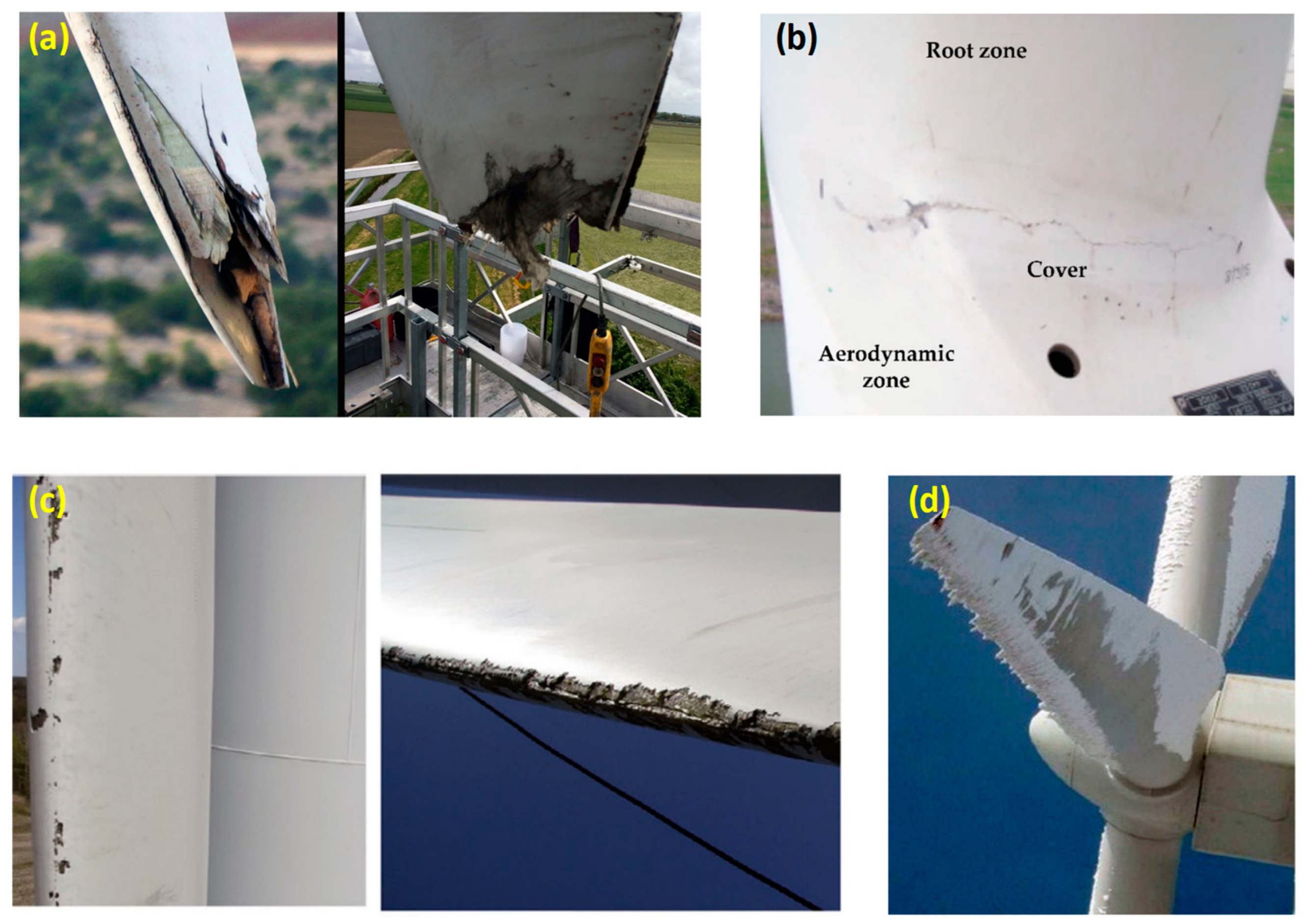
  • Leading-edge erosion is mainly due to airborne particulates in the form of rain, hailstone, sea spray, dust and sand, and UV light and humidity/moisture. As reported in [59], leading-edge erosion can occur after only two years of wind turbine operation, and it is dependent on the site.
  • Structural fatigue damage can occur when the wind turbine is subjected to repeated loads during its life cycle induced by wind. The turbine’s cyclic starts and stops, with yaw error, yaw motion, and vibrational resonance-induced loads from the dynamics of the structure.
  • Damage from icing is caused by the accretion of ice or snow on the blade structures exposed to the icing atmosphere. As reported in [6], there are two distinguished types of atmospheric icing, in-cloud icing (rime ice or glaze) and precipitation icing (freezing rain or drizzle, wet snow). Icing causes added mass and could induce unbalanced vibrations of the blade, resulting in considerable reductions in the economic efficiency of the wind energy project.

2.2. Tower Failure

The structural failure averagely accounted for 12% of the total failure cases, as reported in [4] and shown in Figure 2. Fatigue cracks, joint failure, storm-induced failure, improper installation, and even lighting damage can contribute to the structural failure of wind turbine towers [3,52,60].
  • Fatigue cracks. Different materials can be used for constructing wind turbine towers. From the beginning, a wind turbine tower was made of steel truss-like structures with many connections that could be easily corroded. With increased turbine capacity, steel tubular tubes are preferred for the wind turbine tower design. Harte et al. [61] reported that a steel tubular tower with a height of over 85 m is extremely challenging to balance the dynamical excitation. A concrete tower can be an alternation, but it faces thermal constraints that cause cracking damages in the tower, reducing the stiffness of the whole system. On the other hand, wind turbine towers are often subjected to repeated loads during their life cycle, which can result in fatigue cracks that can expand and carry potential, leading to the tragic collapse of a whole tower.
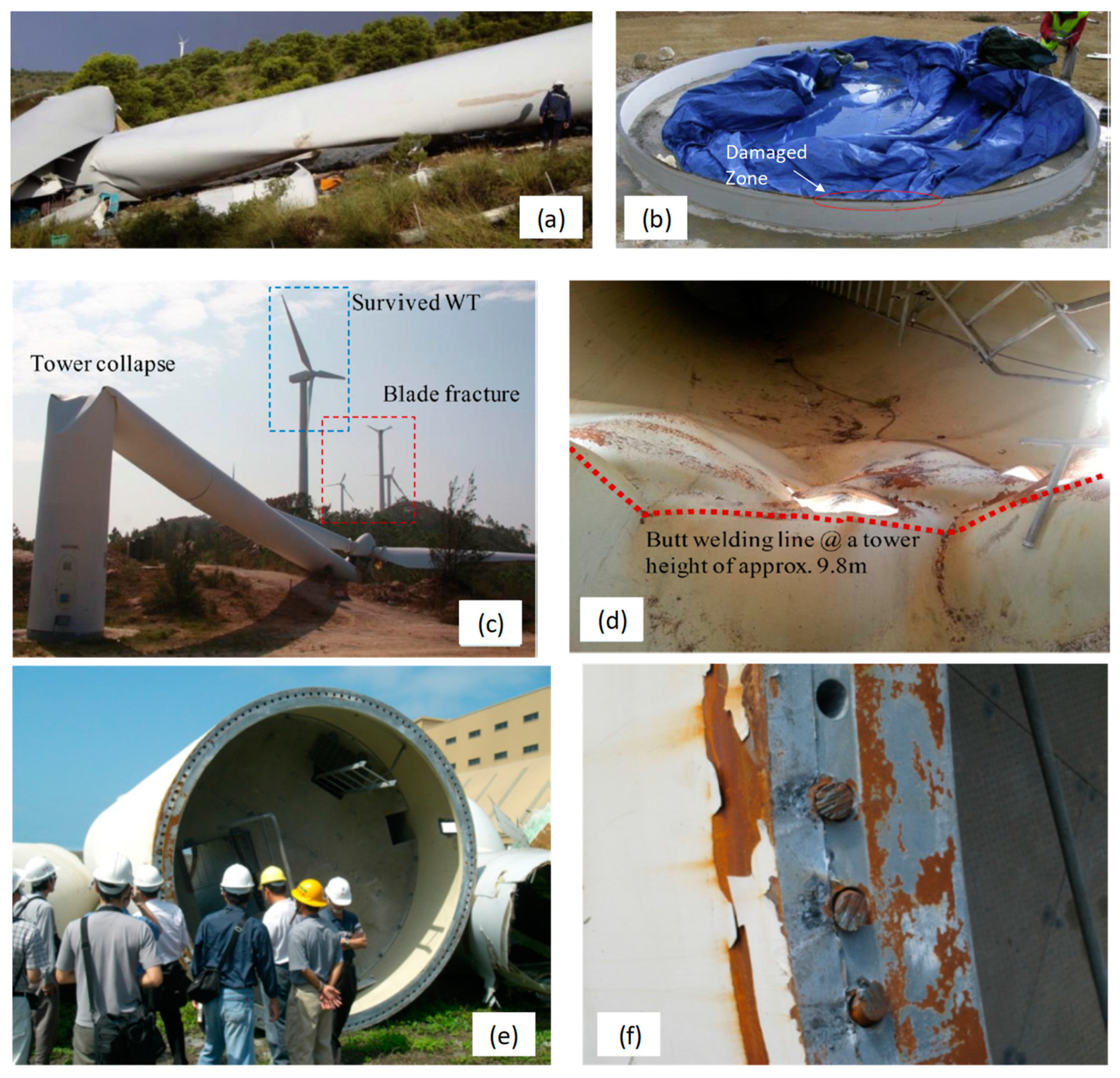
  • Joint failure. In the steel tubular tower, the segments are assembled by high-strength bolts, which are indeed hot spots in the tower. The self-looseness is one of the main reasons for the failure of a bolted joint, especially under transverse loads [62,63]. Regarding the wind tower joint, the bolt failures such as loose and broken could be found during harvesting wind energy [64]. Imbalanced loads across a clamping bolted connection could cause local plastic zones and create proper conditions for corrosion damages [60]. Figure 4a shows the scene of the tower’s structural failure at the wind farm Abuela de Santa Ana in Spain in 2008 [65]. A field investigation found signs of corrosion in the damaged flange section of the joint, which eventually led to the failure of the whole tower, as shown in Figure 4b.
  • Storm-induced failure. A turbine tower could be broken and toppled over during a storm, as reported in [66]. Accidents are ranked the third most common cause of failure [60]. Cheng and Xu [67] investigated the structural failure of wind turbines in China’s Shanwei City caused by the super typhoon Usagi in 2013. The representative tower failure is presented in Figure 4c. The local buckling was observed at the shell wall thickness transition zone in the tower during the typhoon, as depicted in Figure 4d. Their study further reveals that the tubular tower collapsed at a hub wind speed lower than the design survival wind speed. A finite element model was constructed to predict the failure modes and failure locations in the tubular towers caused by the Usagi typhoon [68].
  • Improper installation. In some realistic situations, faulty construction and poor quality control are responsible for the collapse of new turbine structures [3]. As reported in [64], faulty bolt installation related to an insufficient preload at the joint induced the failure of a wind turbine tower in Sweden. In 2008, the Jangmi typhoon struck Taiwan, resulting in strong winds and heavy rains that caused the collapse of a wind turbine [4]. The actual views of the fractured tubular tower section and fractured bolts are depicted in Figure 4e,f, respectively. Chou et al. [4] conducted a failure analysis of the collapsed wind turbine and found that the designed strength of the bolts and the used ones during the construction was different.
  • Lightning damage. Lightning can cause severe damage and even destroy the tower. Wind turbine towers are getting so high and attractive to lightning, primarily when they are frequently located in flat areas with nothing around. Unlike the blades, the tower’s damage related to lightning is rarely observed. A survey of wind turbine tower collapse cases reported that lightning produced only two incidents of the tower collapse, with the occurrence of lightning-related damage being 2.8% [60].

2.3. Substructure and Foundation Failures

Structural damage can be anything in the substructure and the foundation of wind turbines. Different types of potential cracks and damages in concrete foundations have been reported for onshore wind turbines [69]. They occur in the foundations for many reasons, including using substandard concrete mixes, faults in the design, or multi-stage concreting in extreme weather conditions [70].
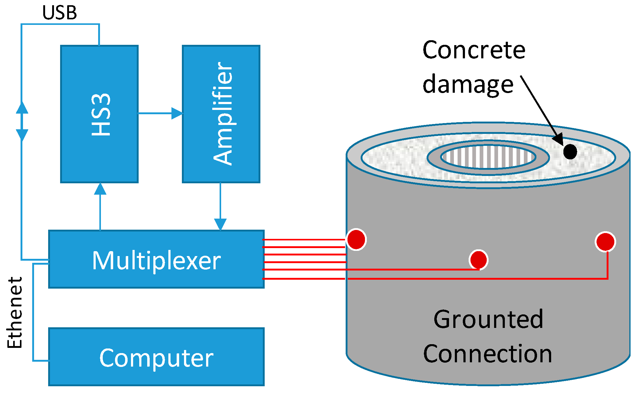
  • Concrete foundation damage. In Germany, in 2000, four turbines experienced sudden and total collapse due to concrete damage at the base. This led to the shutdown of forty-four similar turbines for pending investigation [66]. The steel tower is clamped to the foundation through pre-stalled anchor bolts, and there are many problems in the mortar grout between the steel flange and the foundation. The potential damages can be the vertical shrinkage cracks, the side excess material, the weak mortar grout caused by the separation of the motor, and the voids between the concrete and the tower segments [69]. The combination of the stresses caused by the serviceability load and the thermal stresses could result in cracks in a high concrete foundation pedestal. Cracks can propagate and lead water and dirt from the outside to the inside of the foundation pedestal. Further, the cracks could potentially occur in the transition zones between the insert ring of the tower and the concrete foundation, as reported in [69].
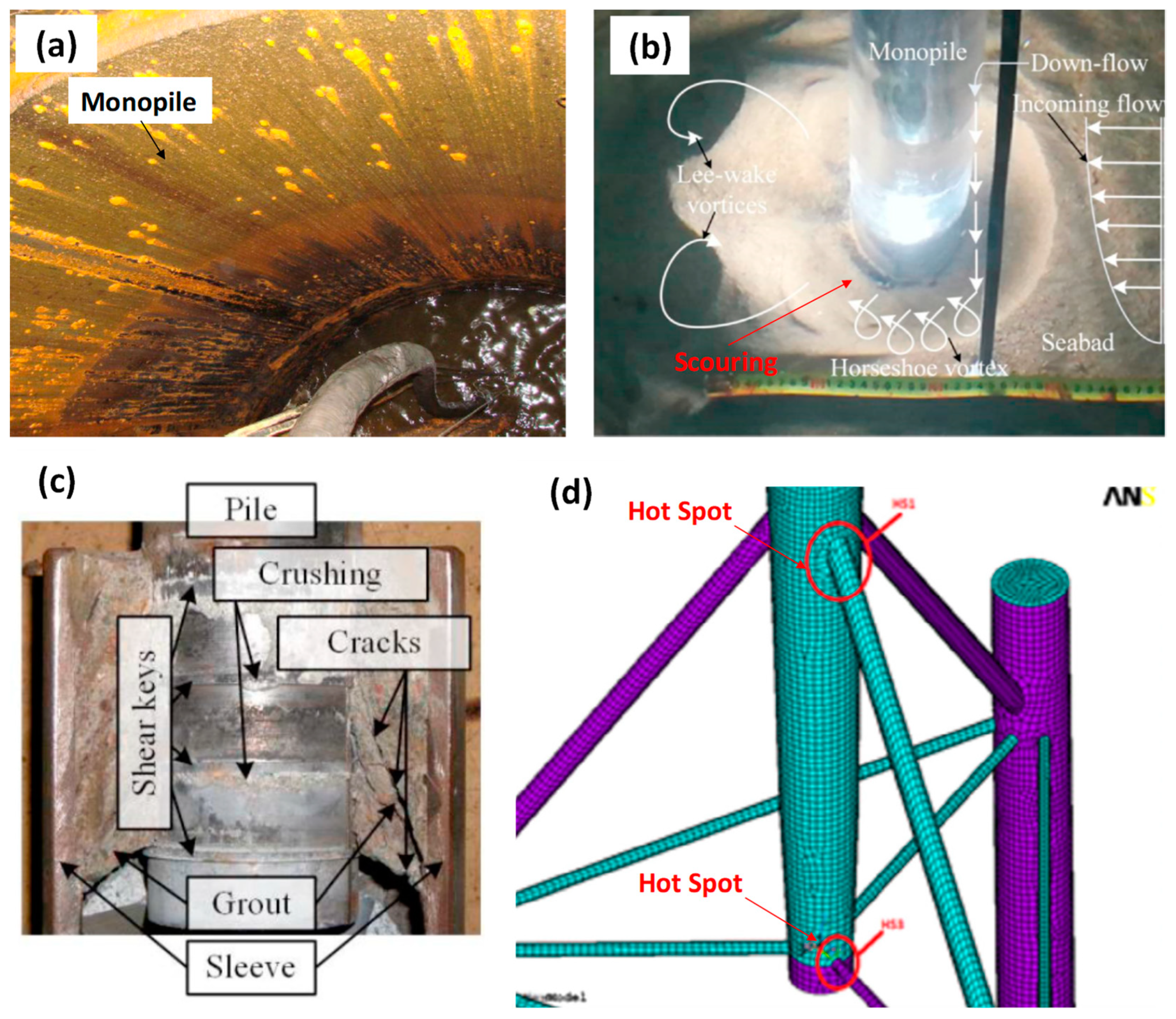
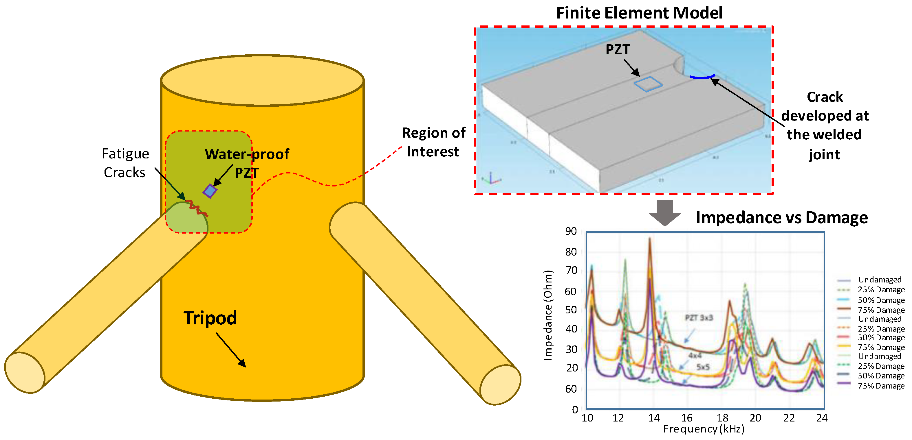
  • Corrosion, scouring, grounded connection failure, and fatigue damage in substruction. The offshore environment is one of the harshest. Under the offshore atmosphere, many potential damages can occur in the substructure and foundation of offshore wind turbines, including corrosion [71,72], scours in the sea bed [73], failure of the grouted connections [74], and cracks in welding/bolted joints [75]. An example of corrosion that has occurred inside a substructure is illustrated in Figure 5a. Many factors influence the rate of corrosion in the offshore atmosphere, such as temperature, humidity, biological organisms, and airborne contaminants [3]. When a wind turbine is placed offshore, locally increased current and wave motions are induced around the structure, resulting in scouring, as depicted in Figure 5b [76]. Grouted connections are commonly used as the structural joint between the substructure and the foundation of an offshore wind turbine [74]. A typical failure of a grouted connection is shown in Figure 5c. Under the different ambient conditions and high dynamical loads caused by waves and wind, the grouted connections are potentially damaged, leading to a reduction in their mechanical stability [77,78], especially severe fatigue damages [74]. The combination of wave and wind loading could also result in fatigue damage in a tripod support structure. The previous analysis of fatigue damage assessment [75] shows that the hot spots (the most severe regions) in the tripod are at the joints between the central column and the bracing members and between the pile and the brace (see Figure 5d).

3. Fundamentals of Impedance-Based SHM

Figure 6 shows two main aspects that must be considered in developing an impedance-based SHM system for a wind turbine structure, including (i) the hardware for impedance sensing and (ii) the interpretation algorithm for damage detection. The hardware consists of a PZT patch surface bonded to a host structure to sense the electromechanical impedance in a frequency domain through an impedance analyzer. Afterwards, interpretation algorithms are implemented to process the impedance signals and assess the host structure’s health status. Since the impedance data consists of the local dynamic information of the structural region near the PZT patches, any structural damages in the host structure could be identified by interpreting the impedance change. In the following sections, those two aspects are briefly described.

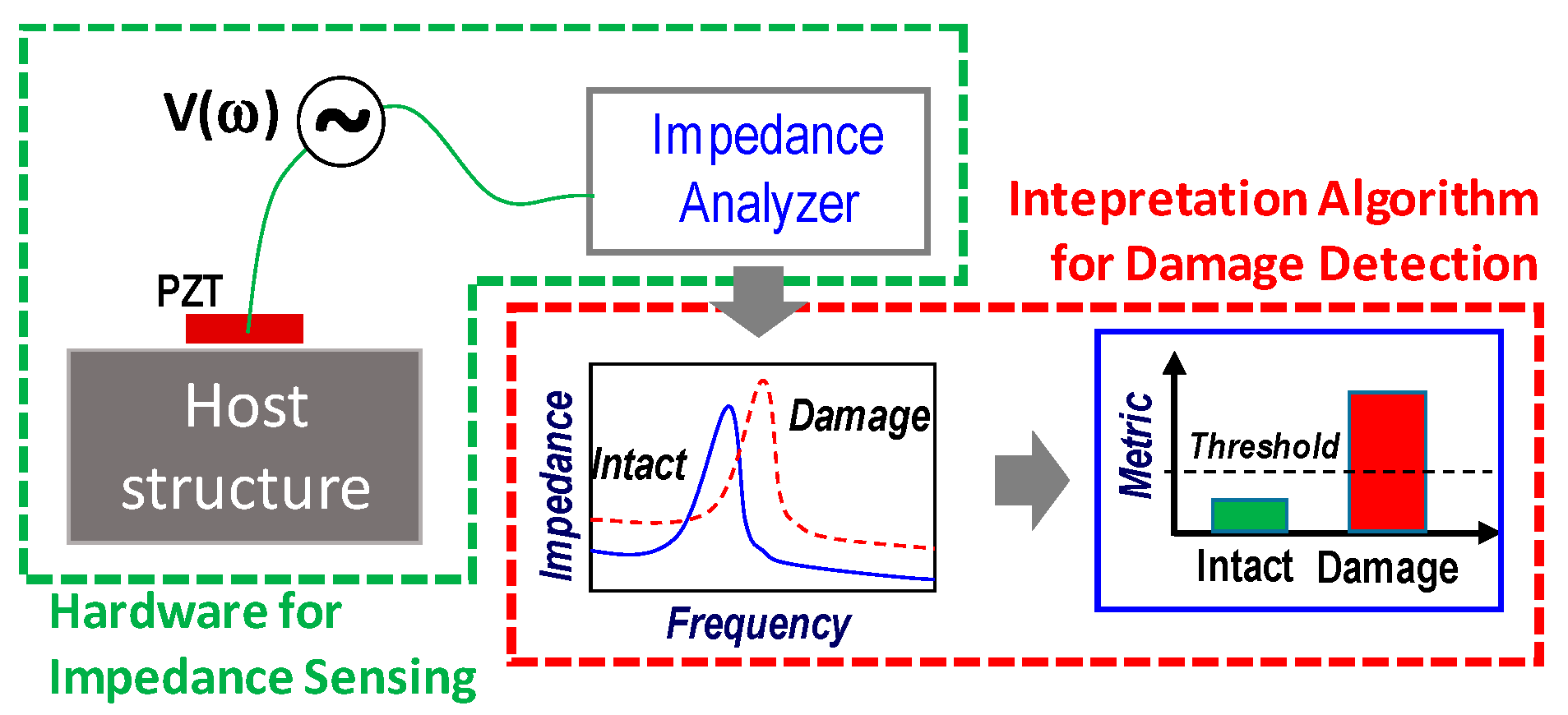
3.1. Impedance Sensing Technology

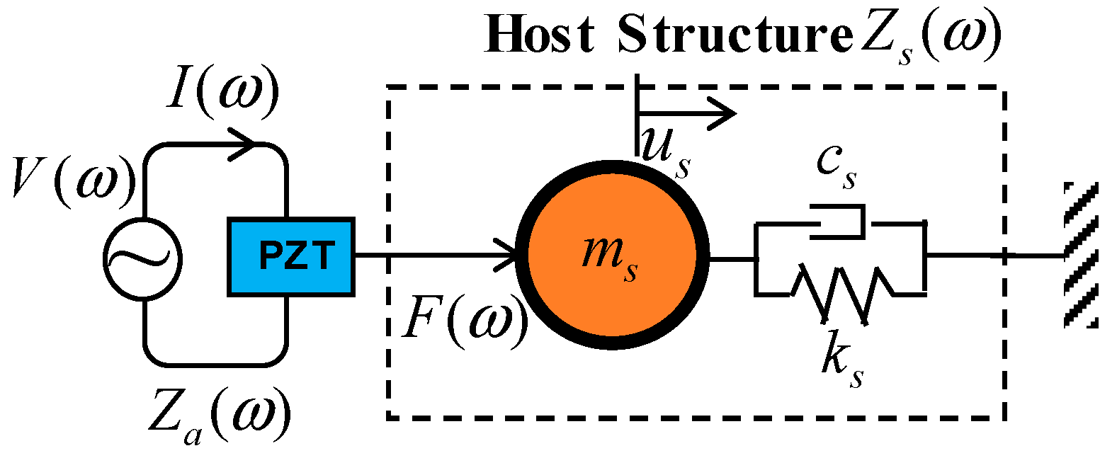
3.1.1. PZT-Driven System

Piezoelectric materials are at the heart of the impedance-based technique. They are smart and low-cost materials that show the potential of converting mechanical energy into electrical energy and vice versa, so they can provide an excellent opportunity to create intelligent, efficient, and effective SHM systems. PZT is today considered one of the most economical piezoelectric elements with a considerable product market. A PZT patch costs only a few dollars, but it can be applied to high-frequency applications at hundreds of kHz and above.
By utilizing the unique piezoelectric effect, Liang et al. [79] developed the electromechanical impedance technique for dynamic analysis and damage detection in structural systems. A theoretical model of the PZT-driven system that can predict the impedance response was proposed in [79]. As shown in Figure 7, the PZT is electrically excited by a harmonic voltage. Under the piezoelectric effect, the PZT is mechanically expanded, and its deformation causes an exciting force at the contact between the PZT and the host structure. The ability of the structure to resist this exciting force is defined as the structural impedance, consisting of the dynamic properties as follows:
Z s ( ω ) = c + m ω 2 k / m ω i
where Zs is the structural impedance of the host structure, the terms m, c, and k are the mass, the damping coefficient, and the stiffness of the host structure, respectively; the term ω is the exciting frequency of the harmonic voltage.
The PZT patch has itself the electrical impedance Za, and the overall electromechanical impedance is a combination of Za and Zs, as expressed in [80]:
Z ( ω ) = V I = { i ω b a h a t a [ ε ^ 33 T 1 Z a ( ω ) / Z s ( ω ) + 1 d 31 2 Y ^ 11 E ] } 1
where Y ^ 11 E = ( 1 + i η ) Y 11 E is the complex form of Young’s modulus of the PZT at a zero electric field; ε ^ 33 T = ( 1 i δ ) ε 33 T is the complex form of the dielectric constant at zero stress; d31 is the 1-directional piezoelectric coupling constant at zero stress; and ba, ha, and ta are the width, the height, and thickness of the PZT, respectively. The terms η is the structural damping loss factor, and δ is the dielectric loss factor of the PZT.
As expressed in Equations (1) and (2), any changes in the structural properties (m, c, and k) as the result of structural damages would lead to the variation in the measured impedance response of the PZT-driven system. Therefore, the structural damage could be assessed by monitoring the change in the impedance response. It is noted that the frequency band of the impedance response should be carefully selected to realize the structural damage. As demonstrated in [81], the effective frequency band should cover the resonant frequencies of the host structure to enhance the opportunity of diagnosing small-size damages. The effective frequency range for a given host structure is obtained by trial-and-error methods or finite element modelling.

3.1.2. Impedance Analyzer

Wired Impedance Analyzers

The impedance or admittance (inverse of impedance) signatures are acquired over a high-frequency range (typically 30–400 kHz). Commercial high-performance impedance analyzers such as Agilent E4980A, LCR meter HIOKI 3532, Wayne Kerr impedance analyzer, and HP 4192A/4194A are commonly-used in impedance-based SHM practices. Generally, a user interface (UI) package is installed on a computer to control the impedance analyzer via an I/O interface. After setting the parameters in the UI, the PZT is interrogated in the impedance analyzer and excited by a harmonic voltage to generate the short wavelength and high-frequency waves into the host structure. The recorded impedance data is then transferred to a computer and saved for data interpretation. Although the commercial impedance analyzers can measure the impedance in a very high-frequency band, up to MHz, they are often bulky, expensive, and inconvenient for field applications.

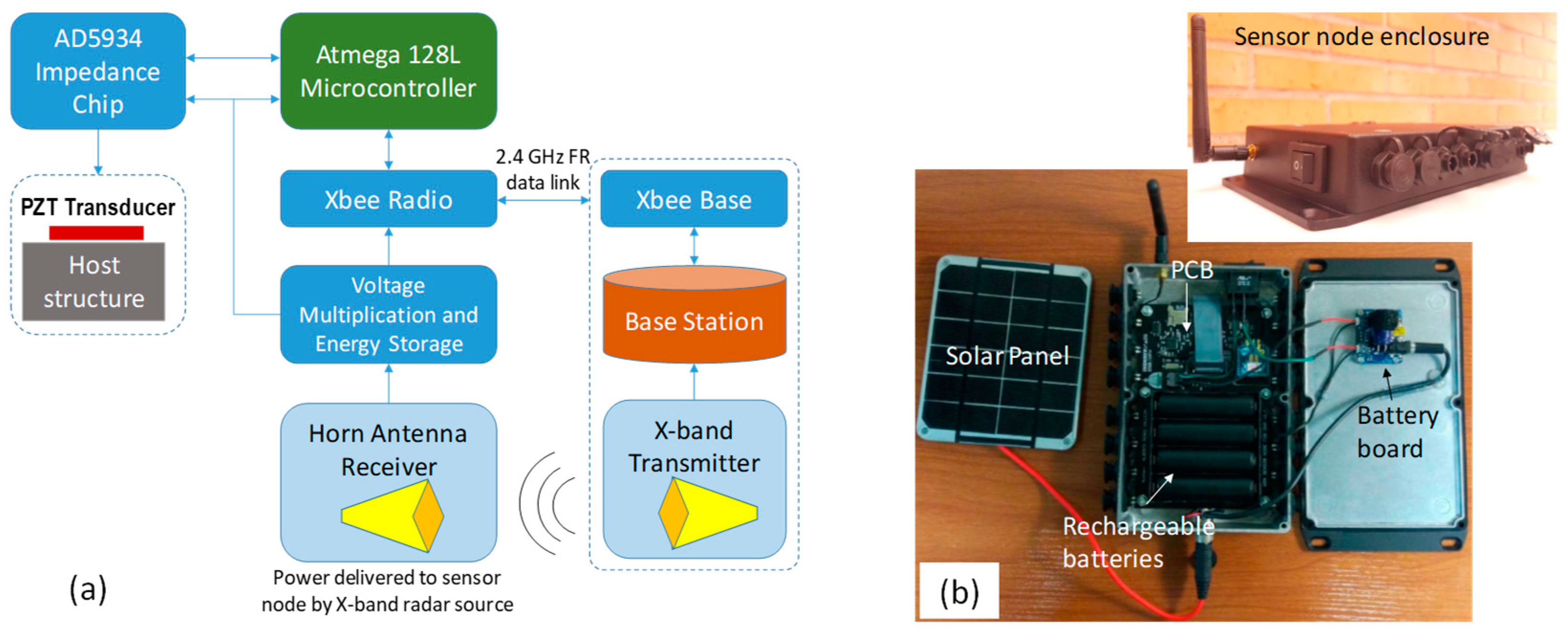
Wireless Impedance Analyzers

Many researchers developed new, low-cost, and portable hardware to reduce the cost and enhance the portability of impedance measurement systems. In 2007, Mascarenas et al. [82] presented the first portable, low-energy consumption, and wireless impedance sensor node, as shown in Figure 8a. The node uses a cheap impedance chip AD5934 for recording the impedance from the PZT [83]. The chip is embedded with multifunctional circuits: function generator, current-to-voltage amplifier, antialiasing filter, analog-to-digital converter (ADC), and discrete Fourier transform (DFT) analyzer. A microcontroller ATmega128L is used for controlling and computing, and a radio frequency module XBee (2.4 GHz Zigbee) wirelessly transmits the recorded data. A microwave wireless energy transmission module powers the node to maximize the portability of the device.
Based on the pioneering study by Mascarenas et al. [82], many researchers have improved the initial prototype to achieve a low-cost multifunctional wireless impedance sensor node. In 2009, Park et al. [84] embedded more functions into the sensor node, such as temperature recording, multi-channel measurement, and a SD memory card slot. A year later, Min et al. [85] embedded damage detection/sensor self-diagnosis algorithms and power management with energy harvesters. In 2012, Nguyen et al. [86] developed an Imote2-platformed impedance sensor node for wireless, autonomous, cost-efficient, and multi-channel monitoring. The Imote2 board could enable high operating speed, low power requirement, large storage memory, and onboard computing capability for onsite applications [87]. To provide stable software and reliable hardware suitable for full-scale and autonomous SHM, Perera et al. (2017) [28] proposed a flexible wireless impedance sensor node, which was also developed on the low-cost impedance chip AD5933. Figure 8b depicts a prototype of the sensor node in which a printed circuit board (PCB) is designed with an AD5933 chip, a multiplexer, an Atmega644PA microcontroller, a wireless XBee S2C 802.15.4 RF module, and a real-time clock DS3221. The battery module includes a solar panel, a battery board MCP73871 and rechargeable batteries for power supply and management.
The in situ applicability of the wireless impedance analyzers was verified for impedance-based SHM of cable-stayed bridges [88] and large girder bridges [85] and building roofs [85]. The solar energy harvesting and consumption, as well as the survivability of the Imote2-based wireless sensor nodes during field testing, were discussed in [88], revealing the stable operation of the designed SHM system. Despite many benefits that a wireless impedance sensor network can offer, the existing wireless sensor nodes can provide only a limited frequency band for impedance measurements, since they have relied on the impedance chip AD5933/AD5934 that can generate signals ≤ 100 kHz.

3.2. Damage Identification Method

3.2.1. Traditional Metrics

For damage detection, the impedance change is traditionally quantified using statistical damage metrics such as root mean square deviation (RSMD), covariance (COV), correlation coefficient deviation (CCD), and mean absolute percentage deviation (MAPD) [22]. The formulas of those standard metrics are expressed in Equations (3)–(6). Each metric exhibits different behaviors in quantifying the impedance change, and the selection of optimal metrics depends on the detection’s purpose or target structure. The RMSD and MAPD metrics are found to be more appropriate for localizing and characterizing the damage growth. Meanwhile, the COV and CCD metrics are more suitable for diagnosing the damage size increment at a fixed location [22]. For monitoring concrete curing and strength gain, it is found that the MAPD metric is better than the RMSD and CCD metrics [89]. As reported in Le et al. [47], the CCD metric is an excellent indicator to detect the prestress force change in the piezoelectric-based smart strand. The RMSD index showed good performance for sensor fault diagnosis, such as sensor debonding and breakage problems [90]. Some researchers used other, less common metrics such as average square deviation (ASD), Rx/Ry, chessboard distance (CD), united mechanical impedance (UMI), ellipse damage index (EDI), and so on. Hu et al. [91] developed an alternative metric, so-called Rx/Ry, and showed that it was more suitable for damage identification in a concrete slab. Another researcher used the chessboard distance (CD) and showed that it was better than RMSD for detecting damage in a composite structure under different temperatures.
RMSD = ( k = 1 N [ Re ( Z k ) j Re ( Z k ) i ) ] 2 k = 1 N [ Re ( Z k ) i ) ] 2 )
MAPD = 1 N k = 1 N | [ Re ( Z k ) j Re ( Z k ) i ] Re ( Z k ) i |
COV = 1 N k = 1 N [ Re ( Z k ) j Re ( Z ¯ ) j ] · [ Re ( Z k ) i Re ( Z ¯ ) i ]
CCD = 1 1 N k = 1 N [ Re ( Z k ) j Re ( Z ¯ ) j ] · [ Re ( Z k ) i Re ( Z ¯ ) i ] σ Z j σ Z i
in which Re ( Z k ) i denotes the real part of the reference impedance signature (i.e., intact state), and Re ( Z k ) j is the real part of the current impedance signature (i.e., unknown state), N is the number of swept frequencies (i.e., the number of data points), and the terms Z ¯ and σ Z signify the mean and the standard deviation of an impedance signature, respectively.

3.2.2. Advanced Damage Identification Algorithms

For damage detection under environmental conditions, alternative damage metrics should be employed. It is noted that the piezoelectric material and the host structure are temperature-dependent [92], and the traditional damage metrics are just statistical comparisons of the two impedance signatures. Thus, the temperature change will indeed induce alternations in the damage metrics, leading to a false damage detection unless the temperature effect is well-compensated. Fabricio et al. [93] observed that the peak frequencies of impedance signatures were reduced when the temperature increased. They also found that the frequency shift was more significant at higher-frequency bands. Several advanced signal processing algorithms have been developed to deal with the effect of temperature change on damage detection results.

Advanced Statistical Index

To remove the temperature effect, Park et al. [94] proposed one of the first temperature compensation algorithms. They verified the proposed algorithm for damage detection in gears, composite reinforced structures, and bolted joints under varying temperatures of 25–75 °C. The temperature compensation algorithm is developed based on the reconstruction of the damage metric through a correction scheme, as expressed by the following equation:
M = i , j = 1 n [ Re ( Y i , 1 ) Re ( Y j , 2 ) ] 2   where   Re ( Y j , 2 ) = Re ( Y j , 2 ) m e a s u r e d + δ s
In Equation (7), the variable M is the sum of the real impedance change squared, Yi,1 is the impedance of the pre-damaged structure at the ith frequency, and Yj,2 is the impedance of the post-damaged structure at the jth frequency; δs is defined as the average difference between the reference impedance and the measured impedance, which can be determined by minimizing the value of damage metric via an iteration process. The experimental result shows that, by incorporating the developed compensation technique into health monitoring applications, the impedance-based technique can detect early-stage structural damage, even with severe temperature variation.
Assuming that the temperature change mainly causes the shift in the impedance pattern, Koo et al. [95] developed a temperature-compensated damage index based on the concept of effective frequency shift. The Koo’s method looks for the maximum value of the CC metric (maxCC) by shifting the effective frequency band. The formula for the maxCC metric can be expressed as [95]:
max C C ω ˜ = max ω ˜ { 1 N i = 1 N ( x ( ω i ) x ¯ ) ( y i ( ω i ω ˜ ) y ¯ ) } / ( σ x σ y )
In Equation (8), x ¯ and y ¯ are the mean of the impedance signature x ( ω i ) and y ( ω i ) , respectively, σ x and σ y are the corresponding standard deviations, ω ˜ is the effective frequency shift, and ω i is the ith frequency. They proposed a strategy combining the maxCC metric with the outliner analysis for damage assessment. They applied the maxCC method to monitor the structural damage in a lab-sized steel truss bridge member. The results show that the proposed strategy can accurately detect a 2-mm cut of the test specimen with a 99.5% confidence level.

Machine Learning Algorithms

Over the past decade, machine learning algorithms have enhanced the automation capability of impedance-based damage detection, which is mainly required for real-time SHM under different environmental conditions. Sepehry et al. [96] presented a radial basis function network (RBFN) for compensating temperature effects on the impedance response of steel plates and bolted joints of a gas pipe. The RBFN learned the impedance signatures corresponding to different temperatures to predict the RMSD metric. Lim et al. [97] developed a kernel principal component analysis (PCA)-based data normalization technique to minimize false alarms caused by varying temperature and loading conditions. Moreover, the proposed technique was successfully verified on a composite aircraft wing under a temperature range of −30 °C to 50 °C (5 °C interval) and a loading range of 10–40 MN (5-MN intervals). The simulated damage was bolt-loosening with a half-turn severity, and the impedance data was recorded in a range of 60–70 kHz (20 Hz interval). The ability of the PCA-based technique for the problem of temperature filtering/compensation is also confirmed by other research groups [98].
Recently, Gianesihi et al. [99] developed a general poly-nominal regression-based methodology to remove the temperature effect during impedance-based SHM. The proposed method was successfully applied to two aluminum beams and one steel pipe with a considered temperature range from −40 °C to 80 °C and a studied frequency range from 10 to 90 kHz. Du et al. [100] developed a convolutional neural network (CNN) model to compensate the effects of temperature change on the impedance response for bolt loosening detection. The model is based on a modified Unet for temperature compensation and a lightweight subnetwork to identify bolt looseness. The proposed model can achieve good damage detection results under the varying temperature condition, even when the network is trained by limited data. The validation accuracy was 97.71% when the model was trained by only about 30 samples from each damage state. The developed model also showed good generality to untrained temperatures and bolt torques.
A promising feature of the machine learning-based models is that they can be retrained to learn new nonlinear temperature and frequency dependences of impedance signatures, so it is readily incorporated into real-time systems. However, one of the important issues is that most machine learning models need to be trained not only by the impedance signature before the failure but also by the data after the failure to ensure the accuracy of damage detection. However, acquiring the training data for damaged states from the structures being used without corrupting them is very challenging. To overcome this issue, Huynh et al. [29] presented a different temperature compensation strategy using a set of the RBFN models to predict the baseline impedance signature at any temperature. The proposed method requires only the impedance data of a healthy state to train the network. As shown in Figure 6, this strategy consists of two main phases: training RBFN for temperature compensation and detecting damage using temperature-compensated impedance signatures, as detailed in Figure 9. In the first phase, the impedance data of the healthy state is recorded under varying temperature conditions and used to build the training data. Then, a set of RBFNs corresponding to all scan frequencies are set up and trained on the recorded data. In the next phase, the impedance data of an unknown state at a temperature T is measured, and the impedance baseline at T is predicted using the trained RBFNs. RMSD and CCD indices are then computed and compared with an upper control limit (UCL) to assess the structural integrity of the monitored structure. The experimental verification on a post-tensioned reinforced concrete girder showed that the proposed method could detect as small as 1 ton prestress loss (roughly 7% damage) under varying temperatures ranging from 6.72 °C to 22.33 °C. Those advanced signal processing algorithms for compensating the operational and environmental effects have enhanced the accessibility of the impedance-based technique for in-field measurements.

4. Current Status of Impedance-Based SHM of Wind Turbines

4.1. SHM of Wind Turbine Blades

An assessment of wind turbine failure cases showed that the blade failure rate is the highest at 23%; see Figure 2 [4]. Therefore, avoiding wind turbine blade failures will lead to significant cost reductions related to the maintenance of wind turbines. Several studies have implemented the impedance-based technique for the SHM of wind turbine blades. Pitchford et al. [49] investigated the experimental feasibility of implementing an impedance system integrated inside turbine blades as a field method to detect turbine blade failure. The experiment procedure can be briefly illustrated in Figure 10a. The test specimen is an actual wind turbine blade section (TX-100 blade) developed at Sandia National Laboratories [49]. Three PZT transducers (made of 20 × 20 × 0.27 PSI-5H4E material, Piezo Systems) are internally bonded to the structural components of the blade, such as skin (Skin PZT) and spar (spar PZT and carbon PZT). Three damage locations (1, 2, and 3) were considered. As shown in Figure 10a, damage location 1 is where the carbon fiber spar cap meets the balsa skin, and damage locations 2 and 3 are the adhesive between the spar flange and the spar cap on the curved side and the other side of the blade, respectively. An HP 4194A impedance analyzer is used to measure the impedance of the PZTs with a 10-Hz resolution. The RMSD index was used to detect and estimate the damage to the blade.
In [49], two different tests, including indirect damage testing and actual damage testing, were performed on the testing blade. In the indirect damage testing, as shown in Figure 10b, magnets of 25 g and a C-clamp were attached to the blade to simulate the added mass and the added stiffness, respectively. To study the sensing range, the mass was moved downward the blade away from the PZTs and stopped at 13, 25, and 40 cm, respectively. The actual damage testing was conducted at locations 1 and 3. As shown in Figure 10c, the notch damage was created at location 1 with a progressive damage severity (deep/wide: 8/3, 15/5, and 19/5 mm). Several notch damages in the form of 2.5-cm-long gaps in location 1 were also created outside the blade with distances of 3, 12, 22, and 31 cm, respectively. As shown in Figure 10d, holes of progressive sizes (4 cm in depth with 1.6, 3.2, 4.8, and 6.4 mm in diameter) were created in location 3. Additionally, holes were drilled in location 3 roughly 5 to 6 cm in depth and 6.5 cm in diameter with distances down the length of the blade of 0, 5, 13, 20, and 28 cm, respectively. The results showed that the impedance in the frequency band 10–60 kHz was suitable for damage detection. All sensors could sense the added mass, the added stiffness, and the notch damage in the blade. The sensors should be positioned on both sides of the blade to sense the damage. It is found that the detection range is about 10–30 cm, depending on the transducer and the type of damage. However, considering the size of the wind turbine blades, such a sensing range seems pretty narrow. Challenges remain to improve the sensing range of PZT patches and optimize their placement on actual wind turbine blades.
The fatigue damage detection in a wind turbine blade was investigated by Huh et al. [48]. In their study, four piezoelectric transducers (PVDF film sensor) were attached to the fixing end of a 10-kW wind turbine blade. The impedance response in 1–200 MHz, the local strain values of the blade, and the maximum deflection were recorded under fatigue loading up to 508,249 cycles. The obtained data revealed the local damage or geometrical change during the experiment. The RMSD metric was used to quantify the impedance change that showed noticeable variations with different sensor locations and fatigue loads. By observing the RMSD change, the fatigue damage was successfully identified.
The crack detection in a commercially purchased wind turbine (WINDMAX) when it was loaded until failure was studied by Ruan et al. [14]. The PZT patches were attached to the top and bottom of the wind turbine blade near the fixing root, and the Agilent 4294A impedance analyzer was used to record the impedance signatures. The blade was undergone increasing loading cycles in which the blade tip was loaded by a displacement of 50, 100, 150, 225, and 250 mm, respectively, while returning to zero displacement before each cycle. The impedance change was also quantified by the RMSD metric. Visual failure of the blade was observed around 225-mm and 250-mm tip displacements and a 0.57-kN load. The recorded impedance data showed rapid changes when the blade nearly failed, leading to significant variations in the RMSD index. The RMSD changes from different sensors provided information about the health status of the blade and the damage location.
Rumsey et al. [101] examined the applicability of MFC (macro-fiber composite) actuators for monitoring the fatigue damage that occurred in a TX-100 blade, which was more massive than the blade tested in the reference [49]. Six MFC patches were installed on the low-pressure (downward-facing) side between 1 and 3 m from the root, where the potential fatigue failure can be expected. The impedance data in 5–60 kHz recorded from MFC patches before the fatigue test showed no resonant peaks and, therefore, no structural information. The recording was continued throughout the fatigue test, but the damage was not successfully detected. This result suggested that the MFC actuators failed to activate local dynamical modes of the tested blade. Thus, selecting sensing material in the impedance-based SHM is a critical issue to secure the success of a damage detection process. Challenges remain for developing novel piezoelectric materials for better sensing mechanisms with higher damage sensitivity and a more extended sensing range for SHM of large-scale wind turbine blades.

4.2. SHM of Wind Turbine Tower

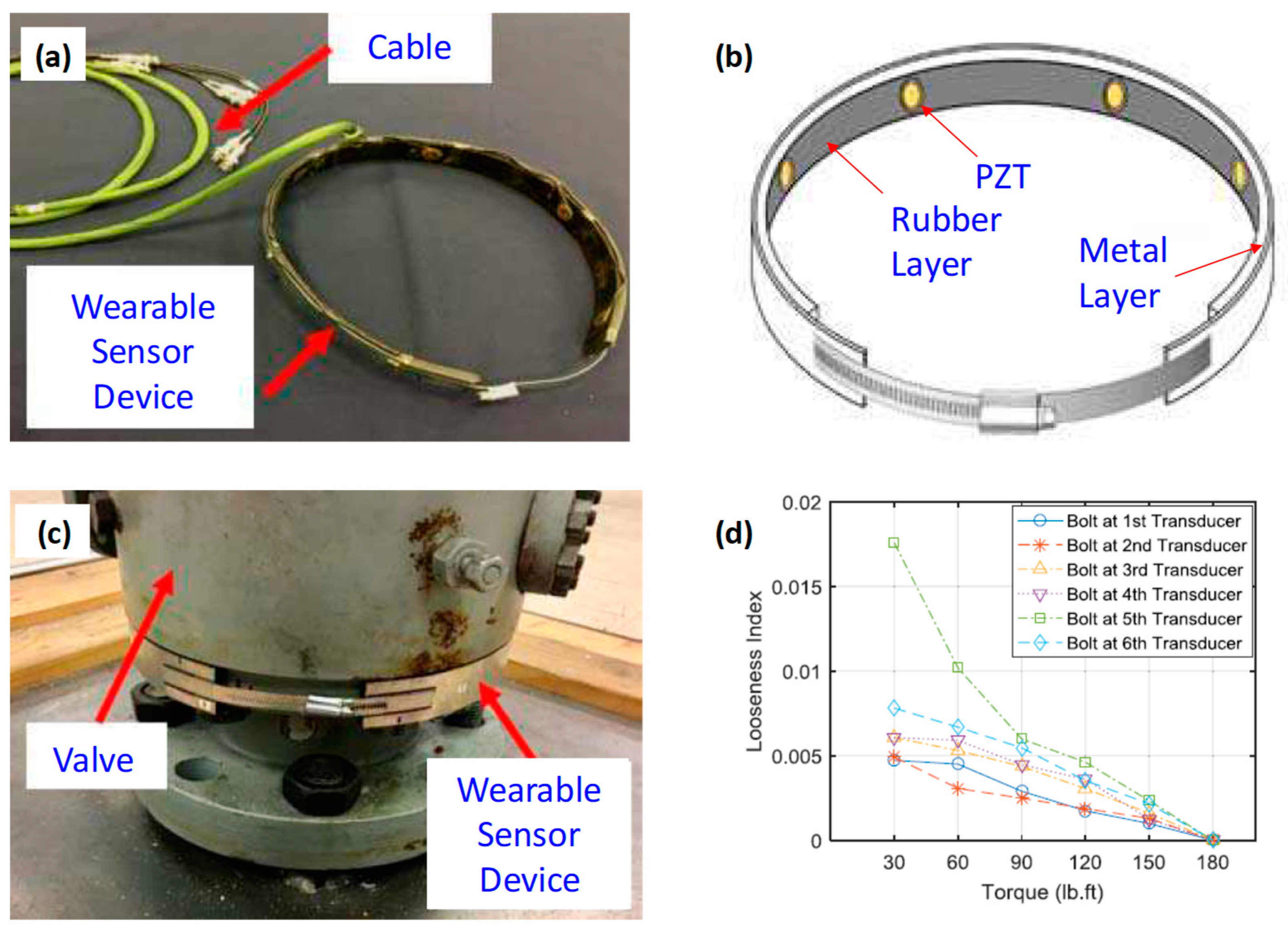
4.2.1. Monitoring of Tower Joint

So far, there have been minimal investigations on the impedance-based SHM of wind turbine towers. Nguyen et al. [52] conducted a pioneered experiment on the feasibility of impedance-based SHM for bolt looseness monitoring in a wind turbine tower. The experimental setup is shown in Figure 11. The test structure was a 300-W wind turbine (1.845 m in height) fixed to the floor through a bolted joint. In their study, several PZTs were patched on the bolted flanges of a lab-scale wind turbine structure, and the joint damage was simulated by sequentially loosening the bolt nuts: B1 and B2, as shown in Figure 11. The PZTs were excited by a high-frequency voltage using a HIOKI 3532 LCR HiTester, and the impedance responses of the joint were then recorded. It is observed that the impedance response in the frequency band of 100–300 kHz, reflecting the local resonances of the joints, was sensitive to the bolt looseness. The looseness of the bolted joint was successfully identified by monitoring the change in the RMSD and CCD indices of the impedance signature. In [52], the impedance-based technique was combined with the vibration-based technique to enhance the damage detection in wind turbine towers. However, the experimented tower model is made of rectangular hollow cross-sections, not tubular cross-sections. Additionally, the effects of the operation of wind turbines and the temperature variation on the impedance response remain unsolved.
Some impedance-based SHM investigations have been conducted on structures with similar geometries to a wind turbine tower. Jiang et al. [102] attempted to identify a minor degree of looseness in flange bolts of a tubular joint. Figure 12 shows the experimental setup, including a NI impedance acquisition system (see Figure 12a) and an eight-bolt flange joint with a PZT patch (PZT-5A φ16 mm in diameter and 1 mm thick) (see Figure 12b) [102]. The impedance was recorded in the frequency band of 350–650 kHz (0.75-kHz intervals). The bolts were initially torqued by 40 Nm in the healthy state. Then, the #7 bolt was loosened with monitor torque reductions ranging from 39.5 Nm to 36 Nm with a 0.5-Nm interval. Pseudo-random noise (ranging from 5 to 30 dBW with 5-dBW intervals) was added to the excitation signal of the PZT during the impedance measurement. The significant impact of the noise on the conductance was observed in Figure 12c. The results show that traditional damage index RMSD, MAPD, CCD, and RMSCR (root mean square of the change ratio) were less effective in detecting minor bolts under the added noise. A new damage evaluation metric (the so-called T index) was developed to deal with the problem of distinguishing minor damage from noise [102]. The test on the eight-bolt flange showed that the indication ranges of the T index were distinguishable for the minor looseness and the noise (i.e., 0.07–0.3 and 0.3–1.2, respectively); see Figure 12d. By comparing the value of the T index with the set threshold, it was able to identify minor bolt looseness in the test specimen.
To enhance the portability, Wang et al. [103] developed a wearable sensor device and successfully applied it to monitor the change in the bolt preload of a bolted flange. As shown in Figure 13a,b, the device comprises PZT transducers protected by a rubber layer and a metallic outer layer that plays as a protection layer. It is also designed with a clamp-through-screw mechanism, allowing the device to be easily attached and removed from the host flange. With an adequate clamping force, the PZTs are contacted with the flange body without using any permanent adhesive layers. Thus, the device can be worn on the tubular structure, thus enabling the applications for wind turbine towers. As shown in Figure 13c, the device was mounted on a 12-bolt flanged valve from which the bolt’s torque was gradually changed from 30 to 180 lb/ft with 30-lb/ft intervals. The impedance was recorded in 40 Hz–110 MHz through an Agilent 4294A impedance analyzer. The normalized RMSD was computed as a bolt looseness index, showing a significant variation under torque changes, as shown in Figure 13d.

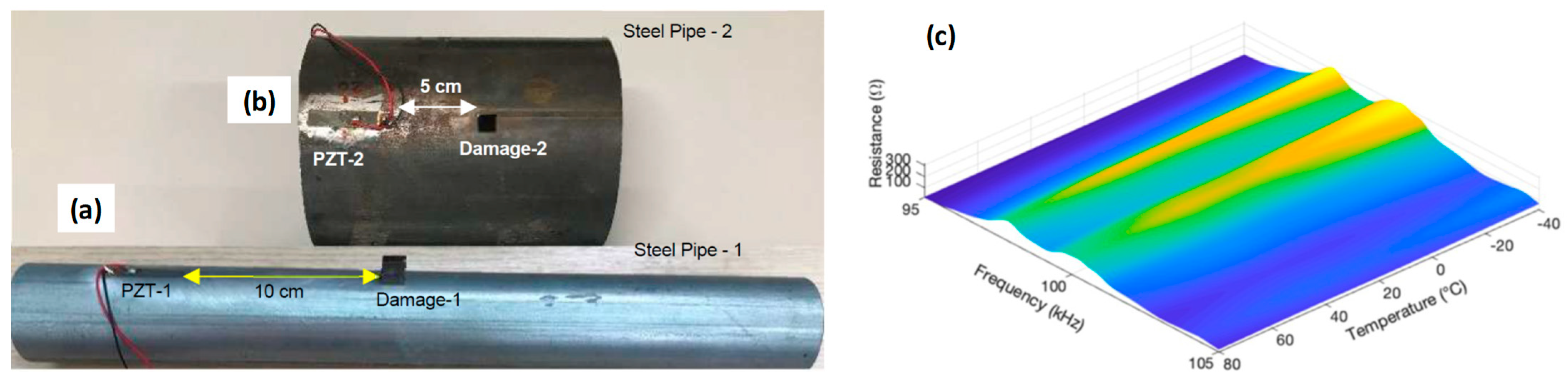
4.2.2. Monitoring of Tower Segment

The impedance-based technique can also detect the local cracks in the tower segment. So far, there has been no study investigating this problem. However, several research attempts have been made to assess the damages in tubular structures such as wind turbine towers by the impedance-based technique [31,32]. For example, Du et al. [31] studied the feasibility of detecting multi cracks in pipeline structures using the PZT array. Two artificial cracks were inflicted on the tested pipe, with the severity ranging from 0 mm to 9 mm. The RMSD index of the impedance was computed as a damage indicator. Their results showed that the impedance-based method could realize the quantitative analysis of the cracks. A theoretical impedance model was developed to provide an insight into the impedance response of a PZT pipe system [32]. Based on this model, a new damage-sensitive feature factor was derived from the mechanical impedance equation for damage identification of pipe structures.
Recently, Antunes et al. [104] mounted the PZT on the outer surface of the pipes (Pipe 1 and Pipe 2) to acquire the impedance response in the frequency range of 5–120 kHz, as seen in Figure 14a,b. Structural damage was simulated by adding the masses to the pipes. They also investigated the varying temperature conditions, ranging from −40 to +80 °C, by putting the pipes into a temperature chamber. Figure 14c shows the shifts in the impedance resonances in a representative frequency range (i.e., 95–105 kHz) along with the temperature change; both vertical and horizontal shifts were observed. A temperature compensation method was designed to improve the damage detection result. The compensation method is efficient and can be applied for the SHM of tubular towers under varying ambient conditions. Since most PZT sensors are flat and brittle, they are not convenient to mount on the curved surfaces of tubular towers unless their sizes are small enough. Challenges remain to design novel piezoelectric transducers, both flexible and durable, to record the impedance response from tubular structures such as wind turbine towers.
Recently, the concept of the wearable sensor device (presented in Section 4.2.1) was extended for pipes’ corrosion and bearing wear monitoring [105]. The lab-scale experiment showed that the corrosion-induced changes in the thickness of the pipe led to a shift in the peak frequency. This experimental investigation has not only evidenced the feasibility of the wearable sensor device but also provided a promising solution for the problem of corrosion detection in the wind turbine tower.

4.3. SHM of Substructure and Foundation

Only a few studies reported the application of the impedance-based technique for SHM of the wind turbine substructure and foundation. Choi et al. [106] investigated the numerical feasibility of the impedance-based technique for welded joint monitoring of an offshore wind turbine substructure. As illustrated in Figure 15, a PZT transducer (type PZT-5A) was supposed to be attached to the central upper joint of a tripod, and its impedance response of 10–24 kHz under different levels of the crack in welding was simulated through the COMSOL program. They observed the apparent shifts in the signature of the impedance peaks that can be used for reliable damage identification. The numerical simulation also investigated the effect of the PZT’s size on the impedance response. Three sizes were considered, including 3 × 3 cm, 4 × 4 cm, and 5 × 5 cm. They observed that the impedance curve was shifted downward with the increasing size of the PZT, while the impedance resonances were relatively stable. However, more numerical analyses and experimental verifications are still needed to verify the proposed idea and optimize the PZT size and placement.
Moll [51] presented a successful preliminary application of the impedance-based technique for monitoring the structural damage occurring in a lab-scale grouted connection. Figure 16 shows the experimental setup of a grouted connection for impedance-based SHM. Six circular piezoelectric transducers of φ10 mm were circumferentially mounted on the outer metal part of the connection. The impedance measurement system includes a computer, a multiplexer, an amplifier, and a frequency generator (HS3), as illustrated in Figure 16. A 4-mm hole with a 35-mm depth was created in the concrete part to simulate the concrete defect, and the corresponding impedance response was recorded at 25–300 kHz. The RSMD index was computed as the damage indicator. The recorded impedance response was altered as the grounded connection was damaged in the concrete part. Moreover, the damage was successfully detected by monitoring the change in the RMSD index. Nonetheless, the simulated damage was not realistic. Additionally, challenges remain in evaluating the durability of the transducer under the marine atmosphere and the effect of varying environmental and loading conditions on the damage-detectability.

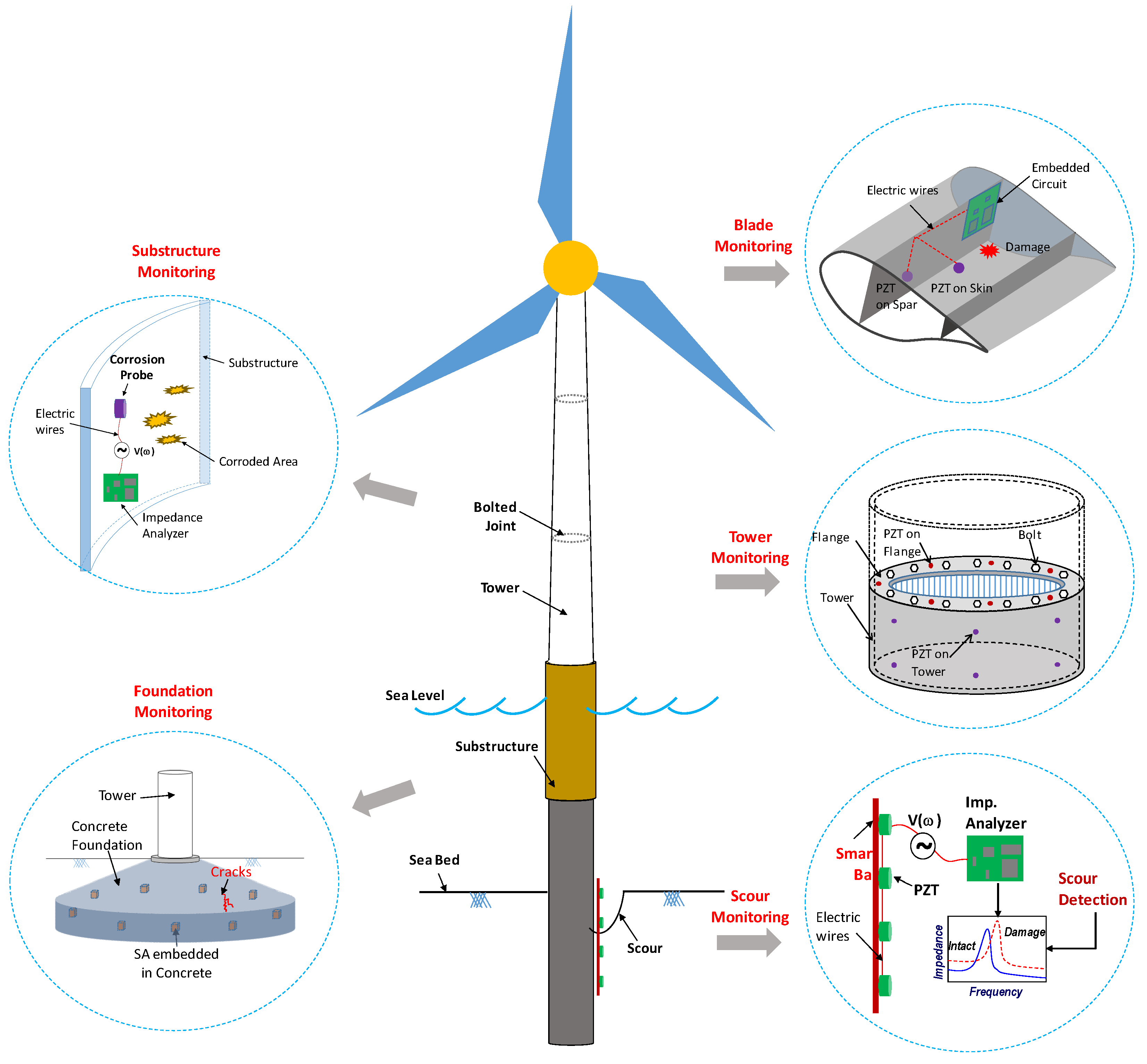
5. Future Perspectives of Impedance-Based SHM of Wind Turbines

The above literature review shows that the impedance-based technique has been insufficiently explored for wind turbines. Due to its potential for developing one of the most effective SHM systems, new applications of the impedance-based technique for the SHM of wind turbines will be indeed discovered. In Figure 17, we suggest five main research topics that can contribute to the translation of the impedance-based technique to practical applications in wind turbine monitoring. They include blade monitoring, tower monitoring, substructure monitoring, foundation monitoring, and scour monitoring. In the following sections, those suggested research topics are discussed.

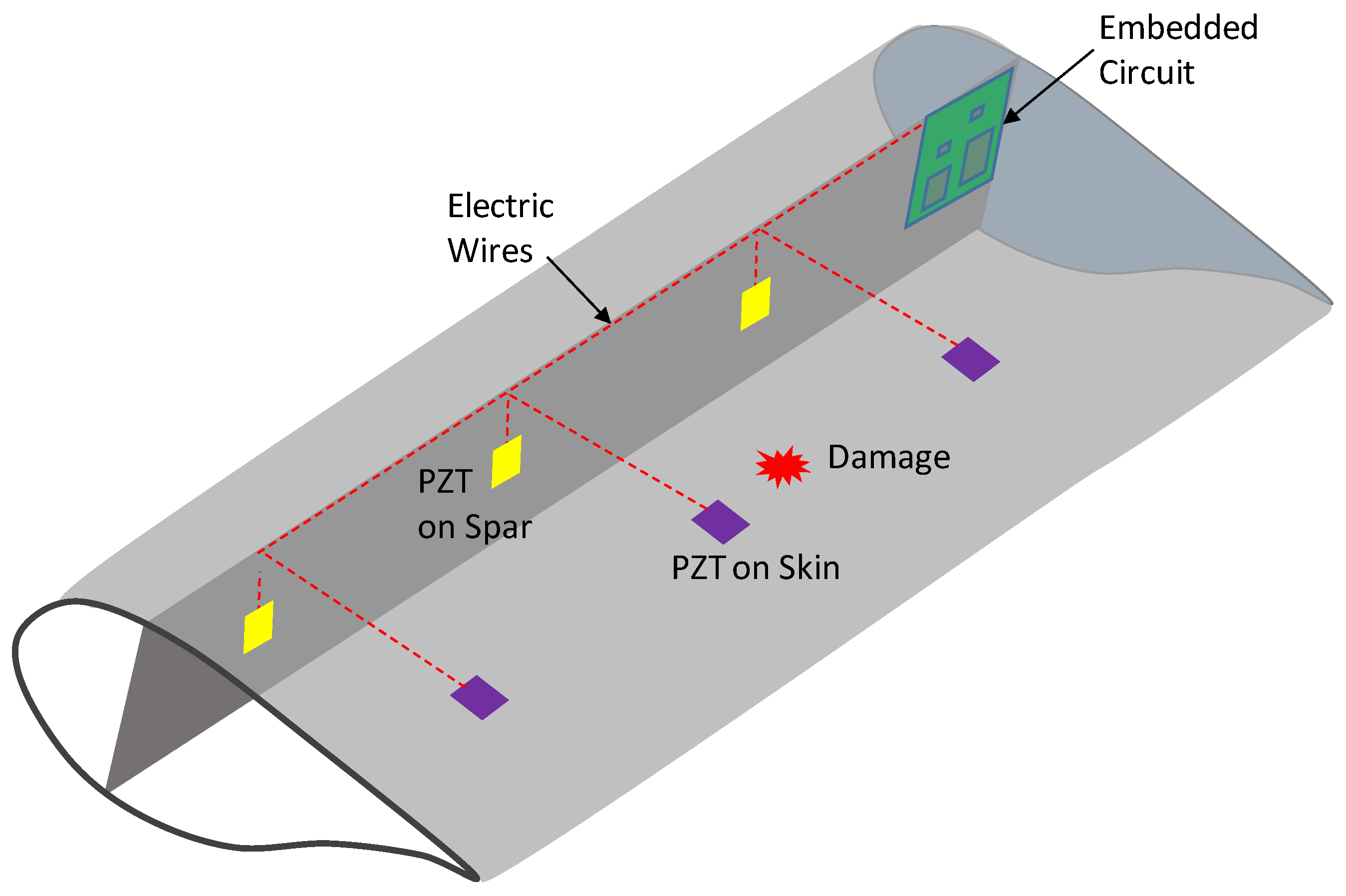
5.1. Blade Monitoring

So far, the impedance-based technique has been mainly applied for fatigue damage detection in wind turbine blades. Therefore, more research is needed to explore this innovative technology for detecting other types of blade failures, such as damage from lightning, damage from atmospheric icing, and leading-edge erosion. Since the impedance characteristics corresponding to those damages could be different, the damage severity prediction model corresponding to each failure should be developed for quantitative SHM of wind turbine blades.
A previous experiment by Pitchford et al. [49] showed that an added mass to a wind turbine blade led to variations in the impedance signature. Since the added mass can be considered a freezing growth, this experiment holds promise for detecting ice on the blade [107]. However, more numerical and experimental investigations are needed to make this idea a reality. Leading-edge erosion is related to the loss of the material and the change in the geometrical parameters of the wind turbine blade. The impedance-based technique could feasibly detect the wind turbine blade’s mass, according to the reference [49]. The lightning causes delamination, shell debonding, and tip detachment in the blade, and such damages could be potentially identified through the impedance-based technique based on some previous investigations [108,109].
A typical structural design has a critical bolted joint at the blade root, which should be adequately monitored. The impedance-based technique has been regarded as a promising tool for loosened bolt monitoring [37,110,111]. Therefore, there is a need to develop a bolt looseness monitoring system for the blade root of a wind turbine structure. As reported in [101], the MFC was insensitive to a thick blade’s damage due to its weak piezoelectric excitation. Therefore, selecting the piezoelectric transducers corresponding to a target wind turbine blade could play an essential role in the success of an impedance-based damage detection process. This deserves a future intensive investigation.
The previous study proposed a smart blade concept for guided wave-based SHM [112]. Based on this concept, we introduce an impedance-based smart blade for the impedance-based SHM, as shown in Figure 18. The piezoelectric-based smart blade is embedded with self-powered PZT nerves and embedded signal conditioning and data acquisition circuits for wireless and autonomous sensing. The blade vibration-induced energy can be harvested to power the SHM system. Since the impedance-based technique has a limited sensing range for each PZT transducer, a smart blade should be developed with dense PZT nerves to provide the health status of any points on the blade.
Additionally, the survivability of PZT sensor systems during a lightning occurrence is also an important issue. The PZT sensors close to the area struck by lightning can be heated up to tens of thousands of degrees Celsius. During such high temperatures, the piezoelectric materials, bonding layers, and soldering components of the sensors can be damaged, threatening the regular operation of the monitoring system. Nonetheless, one of the promising features of piezoelectric impedance-based SHM technology is sensor self-diagnosis. Thus, a sensor (i.e., breakage or debonding) damaged can be timely identified using the inverse of impedance signature, which further improves the reliability of operating SHM system during a lightning occurrence [22,27]. The impact of lightning on the survivability of the PZT sensors is a good research topic that needs to be studied further in the future.

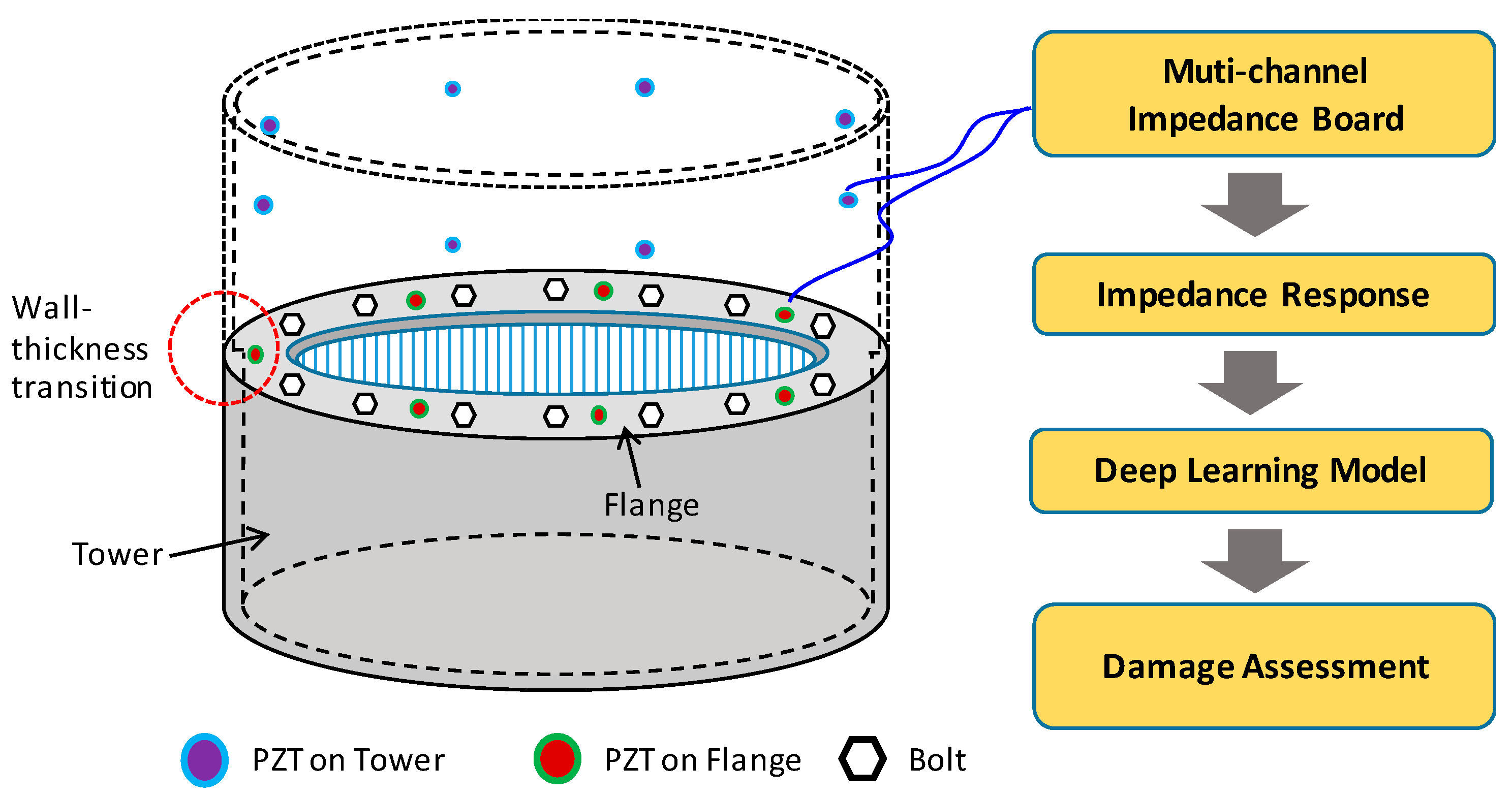
5.2. Tubular Tower Monitoring

Researchers have paid less attention to the tower failures than blade failures [65]. Although there have been some successful applications of the impedance-based technique to structures with similar geometry to a wind turbine tower, such as pipelines and bolted flanges [102,104], there is a long way to go for this technology to be transferred into real SHM applications. To guarantee the successful translation, we need a comprehensive study of the impedance characteristics, the sensing range, and the effective frequency band of the PZT mounted on both lab-scale and real-scale wind turbine towers. Realistic/near-realistic damages such as fatigue cracks, bolt looseness, lightning, and corrosion should be investigated to evaluate the practicality of the impedance-based technique. Additionally, there is a need to extensively investigate the influence of offshore environmental changes on the impedance responses and develop robust compensation techniques.
Figure 19 illustrates an example of PZT deployment on the tower for impedance-based SHM. Lessons learned from the previous accidents [67,68] show that the shell wall-thickness transition areas of the tower are hot spots where local buckling could have occurred. Thus, a PZT network should be designed and deployed in those hot spots to monitor the local buckling damage; see Figure 19. Additionally, the fracture could have happened at the bolted joint of the tubular tower segments [4]. It is therefore necessary to install PZT on the flange to monitor multiple bolts simultaneously. A multi-channel impedance board is developed to record the impedance from the number of PZT patches in real-time. Efficient deep learning models are developed to autonomously extract the damage-sensitive impedance features from the recorded data and identify the damage type, location, and extent of the quantitative SHM of the tower (e.g., convolutional neural networks [25,113] and graph convolutional network [114]). Besides the fracture and local buckling, the PZT network can also be used to monitor the tower’s cracks and corrosion.
As reported in [115], the sensing range of an individual PZT patch is dependent on the material and the density of the monitored structure. Considering the limited sensing range of a PZT patch, it is necessary to develop an optimal PZT network that can be used to monitor the whole wind turbine tower effectively. For a large and high tower, it is necessary to determine the hot spots in the structure and optimize transducer placement to reduce the number of transducers and the cost of the SHM system. The research on PZT placement, considering the installation cost and the efficiency, also deserves intensive investigation.
To reduce the cost of SHM systems, along with enhancing the damage detectability, a research trend is to combine the local impedance-based technique with other techniques (i.e., guided wave method, thermal imaging technique, fiber optic method, laser vibrometer technique, and vision-based approach) to build a hybrid system. In [52], the authors developed a hybrid SHM strategy that combines the local impedance-based technique with the global vibration-based technique to enhance the damage detection result of a wind turbine tower. Both accelerometers and PZT patches were attached to the flanges of the tower, and their recorded responses are fused to detect potential damages. However, this study did not consider other potential damages, such as cracks and corrosion. Additionally, the effect of the rotor’s vibration on the impedance response was not investigated.
Developing impedance-based low-cost portable/wearable devices for the SHM of wind turbine towers is suggested for future research. Some preliminary studies have developed piezoelectric wearable devices with cost-effectiveness, portability, a predictable frequency band, and real-time applicability [46,86,103]. For example, Huo et al. [110] embedded a PZT transducer into a ring to develop the concept of the smart washer for single-bolt monitoring. Wang et al. [103] developed a wearable sensor device for bolt group monitoring. The prototype of the wearable sensor device and its experimental verification for impedance-based SHM were previously described in Section 4.2.1. The device (comprised of many PZT transducers) can be worn on a tubular joint/segment of the tower through a clamping mechanism to collect the impedance responses, which are then used for further health monitoring and damage assessment. Despite the preliminary successful verification results [103,105,110], the application of wearable sensor devices for the impedance-based SHM of wind turbine towers has not been explored. For this purpose, a large-size wearable sensor device needs to be designed, and its durability and repeatability performance should be sufficiently investigated before real applications.
Recent developments in machine learning and artificial intelligence have opened alternative doors toward processing impedance signals. Early studies have explored the application of artificial neural networks (ANN) for impedance-based damage detection [116] and compensation of the effect of temperature on the impedance [29]. There is also some research developing principal component analysis (PCA) models for the impedance-based SHM [98]. Some authors explored combining a convolutional neural network (CNN) with the impedance-based technique for damage detection [113]. However, those models were not fully automated due to the requirement of preprocessing impedance signals. More research is needed to develop new machine learning-based algorithms for processing impedance data with fast operations, higher accuracy, automatic damage-sensitive feature extraction, and real-time performances.

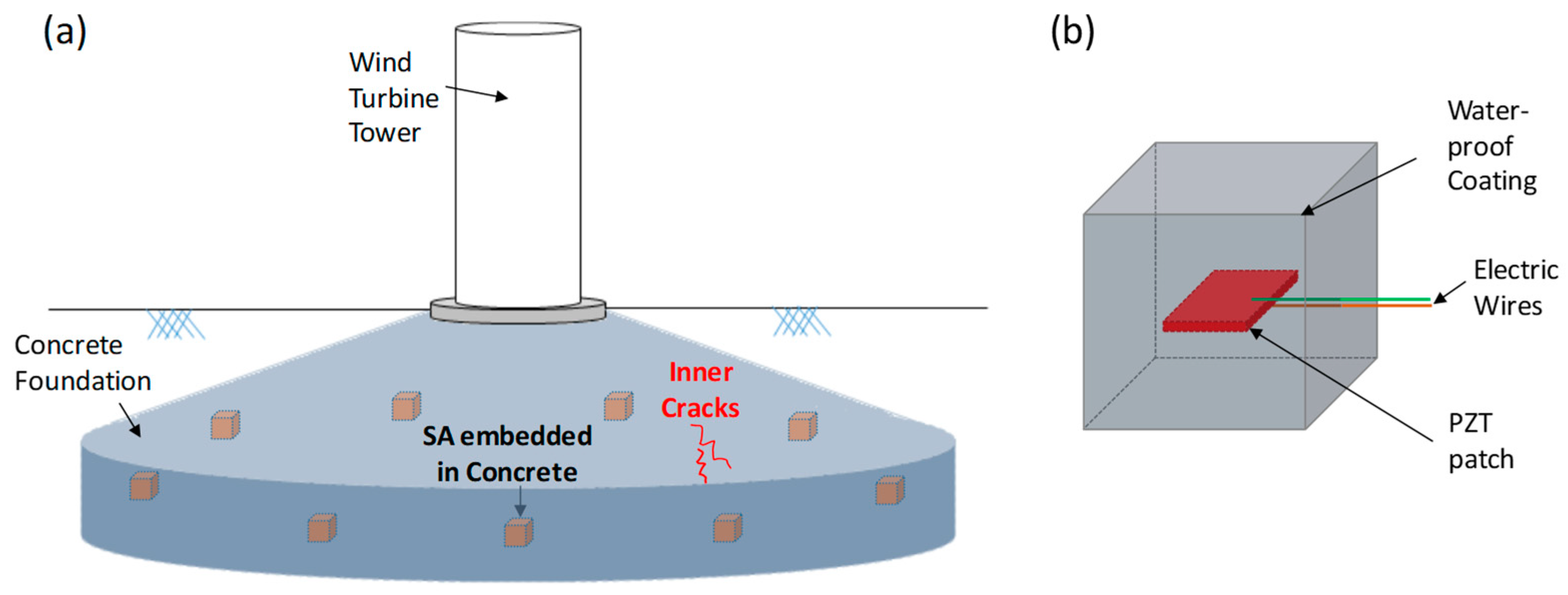
5.3. Substructure and Foundation Monitoring

Over the past decades, the impedance-based technique was extensively studied and applied for the SHM of concrete structures. Many numerical and experimental investigations have been conducted to monitor concrete crack, curing, reinforced rebar corrosion, and crack repair [33,34,117,118,119]. For example, Liu et al. [120] applied the technique for assessing concrete’s freezing–thawing and crack damage and proposed a mathematical method to evaluate the development of concrete damage. Their result showed that the RMSD index increased with the development of the freezing–thawing cycles and crack depth, and the most effective frequency band was found at 100–150 kHz. Zhang et al. [121] studied the relationship between the stage of the cement setting process and the resonant frequency shift of impedance peaks to monitor early-age hydration and the setting of cement paste. Ahmadi et al. [122] monitored the corrosion of rebars embedded in concrete blocks and the admittance responses under different levels of corrosion. In their study, the equivalent structural parameters extracted from the admittance response were found as effective indicators for detecting and quantifying the corrosion damage in rebars. However, the PZT patches are brittle and easily damaged. To overcome such issues, some authors embedded a PZT patch inside a concrete block to form a smart aggregate (SA) [33,123]. As a multifunctional device, a SA can be used as both actuator and sensor, making it ideal for impedance-based SHM of concrete parts in wind turbine systems.
Despite the impedance-based technique has been a mature technology and the SA technique has been extensively studied, their application for offshore/onshore foundation monitoring has not been explored so far. In Figure 20, we propose an idea to embed the SAs inside the foundation of the onshore wind turbine to monitor inner cracks. The impedance response of the distributed SAs is continuously monitored, and the impedance shift can be quantified to predict crack locations. The idea presented in Figure 20 needs sufficient numerical and experimental investigations to convert it into a reality. Additionally, intelligent algorithms based on machine learning to predict damage locations are also suggested for future studies.
To offshore wind turbines, scour is one of the main concerns. Due to its merits, the impedance-based technique could play a vital role in developing low-cost scouring systems for offshore foundations. In Figure 21, we propose a piezoelectric-based smart bar that can be used for monitoring foundation scouring. Several PZT patches are waterproof and bonded to a stainless-steel bar to form a smart bar, which is then inserted into the sea bed next to the foundation (such as a monopile in Figure 21). The operating principle is that the scour will cause the looseness/removal of the material around each PZT patch, leading to the variations of the impedance responses. The scouring depth could be identified by analyzing the damage metrics of the PZT patches.
It is also needed to explore the application of the impedance-based technique for detecting corrosion in offshore wind turbines. The early study showed that the resonant frequency shift of the impedance peaks was proportional to the corroded area [124]. Zhu et al. [125] investigated the use of mechanical impedance to estimate the corrosion damage progression of a steel beam quantitatively. Li et al. [41] developed a PZT-based smart corrosion coupon and established the relationship between the corrosion-induced thickness loss and the impedance variation for comprehensively monitoring the corrosion amount. Future research efforts are required to develop piezoelectric-based corrosion transducers that can be applied for the SHM of offshore towers and substructures. Under the marine condition, protection technologies should also be developed for those piezoelectric devices to secure their functionality during the impedance monitoring process.

6. Conclusions

In the past decades, the impedance-based technique has been extensively studied for SHM of different civil engineering structures. Thanks to its merits, including cost-effectiveness, easy implementation for complex structures, robustness to early-stage damages, and online and autonomous damage assessment, the impedance-based technique has the potential to create one of the most effective SHM systems. Nonetheless, its SHM applications in the wind energy industry have been limited. Therefore, this paper was motivated to present the current status and propose new research topics for impedance-based SHM of wind turbines.
The contributions of this review paper lie in:
(1)
Focusing on the applicability of the impedance-based technique for SHM of different structural components such as blades, towers, substructures, and foundations;
(2)
Identifying research needs for improving the performance of the impedance-based SHM of wind turbines;
(3)
Proposing innovative concepts for the future development of an effective impedance-based SHM system in the green energy field.
The proposed concepts include (i) the piezoelectric-based smart wind turbine blade with a self-powering and embedded circuit for real-time SHM purposes, (ii) the piezoelectric-based smart bar to monitor the scour damage occurring around an offshore wind turbine foundation, (iii) the PZT-based corrosion probe for monitoring the structural conditions of a tower and substructure, (iv) the wearable sensor device for the SHM of wind turbine towers and bolted joints, and (v) innovative SA technologies for quantitative damage estimations on the concrete foundations of wind turbines.
There are still many challenges to substantiate the application of the impedance-based technique for wind turbine tower monitoring and to ensure the smooth transition of this technology from research to practice. Besides the above-mentioned topics, several engineering issues remain for (i) enhancing the sensing range of PZT patches and optimizing their geometrical parameters considering the sizes of wind turbine structures; (ii) designing a method of protection for PZT patches from harsh environmental conditions, especially extreme offshore conditions, to secure their functionality and reliable damage detection; (iii) developing new piezoelectric materials with better sensing mechanisms, higher damage sensitivity, and a more extended sensing range and durability under a marine atmosphere; (iv) developing innovative algorithms based on artificial intelligence and machine learning for compensating the effects of marine conditions on the impedance response and minimizing false damage identifications; and (v) designing novel wireless impedance sensor nodes with higher measurable frequency bands, up to MHz, for practical applications.
We are in the early stage of the discovery journey towards the practical application of the impedance-based method in the wind energy industry. Many research efforts need to be carried out to verify the feasibility and evaluate the practicality of the impedance-based technique for lab-scale and real-scale wind turbine towers. However, the unique advantages of the impedance-based SHM technology pose it as a possible important tool for the SHM of wind turbines in the green energy field.

Author Contributions

Conceptualization, T.-C.H., D.-D.H. and T.-C.L.; methodology, T.-C.H., D.-D.H. and T.-C.L.; formal analysis, T.-C.H., T.-H.N., T.-H.-T.L. and H.-P.N.; writing—original draft preparation, T.-C.H. and T.-C.L.; writing—review and editing, T.-C.H., T.-H.-T.L. and D.-D.H. All authors have read and agreed to the published version of the manuscript.

Funding

This research received no external funding.

Acknowledgments

We acknowledge the support of time and facilities from Ho Chi Minh City University of Technology (HCMUT), VNU-HCM for this study.

Conflicts of Interest

The authors declare no conflict of interest.

References

  1. Luderer, G.; Pietzcker, R.C.; Carrara, S.; de Boer, H.S.; Fujimori, S.; Johnson, N.; Mima, S.; Arent, D. Assessment of wind and solar power in global low-carbon energy scenarios: An introduction. Energy Econ. 2017, 64, 542–551. [Google Scholar] [CrossRef] [Green Version]
  2. Wiser, R.; Rand, J.; Seel, J.; Beiter, P.; Baker, E.; Lantz, E.; Gilman, P. Expert elicitation survey predicts 37% to 49% declines in wind energy costs by 2050. Nat. Energy 2021, 6, 555–565. [Google Scholar] [CrossRef]
  3. Ciang, C.C.; Lee, J.-R.; Bang, H.-J. Structural health monitoring for a wind turbine system: A review of damage detection methods. Meas. Sci. Technol. 2008, 19, 122001. [Google Scholar] [CrossRef] [Green Version]
  4. Chou, J.-S.; Tu, W.-T. Failure analysis and risk management of a collapsed large wind turbine tower. Eng. Fail. Anal. 2011, 18, 295–313. [Google Scholar] [CrossRef]
  5. Adedipe, O.; Brennan, F.; Kolios, A. Review of corrosion fatigue in offshore structures: Present status and challenges in the offshore wind sector. Renew. Sustain. Energy Rev. 2016, 61, 141–154. [Google Scholar] [CrossRef]
  6. Katsaprakakis, D.A.; Papadakis, N.; Ntintakis, I. A Comprehensive Analysis of Wind Turbine Blade Damage. Energies 2021, 14, 5974. [Google Scholar] [CrossRef]
  7. Shafiee, M.; Brennan, F.; Espinosa, I.A. A parametric whole life cost model for offshore wind farms. Int. J. Life Cycle Assess. 2016, 21, 961–975. [Google Scholar] [CrossRef] [Green Version]
  8. Shafiee, M.; Zhou, Z.; Mei, L.; Dinmohammadi, F.; Karama, J.; Flynn, D. Unmanned Aerial Drones for Inspection of Offshore Wind Turbines: A Mission-Critical Failure Analysis. Robotics 2021, 10, 26. [Google Scholar] [CrossRef]
  9. Martinez-Luengo, M.; Kolios, A.; Wang, L. Structural health monitoring of offshore wind turbines: A review through the Statistical Pattern Recognition Paradigm. Renew. Sustain. Energy Rev. 2016, 64, 91–105. [Google Scholar] [CrossRef] [Green Version]
  10. Balageas, D. Introduction to Structural Health Monitoring. In Structural Health Monitoring; Wiley Publisher: New York, NY, USA, 2006; pp. 13–43. [Google Scholar]
  11. Gómez Muñoz, C.Q.; García Márquez, F.P. A new fault location approach for acoustic emission techniques in wind turbines. Energies 2016, 9, 40. [Google Scholar] [CrossRef] [Green Version]
  12. Rizk, P.; Younes, R.; Ilinca, A.; Khoder, J. Wind turbine blade defect detection using hyperspectral imaging. Remote Sens. Appl. Soc. Environ. 2021, 22, 100522. [Google Scholar] [CrossRef]
  13. Wang, P.; Zhou, W.; Bao, Y.; Li, H. Ice monitoring of a full-scale wind turbine blade using ultrasonic guided waves under varying temperature conditions. Struct. Control Health Monit. 2018, 25, e2138. [Google Scholar] [CrossRef]
  14. Ruan, J.; Ho, S.C.M.; Patil, D.; Song, G. Structural health monitoring of wind turbine blade using piezoceremic based active sensing and impedance sensing. In Proceedings of the 11th IEEE International Conference on Networking, Sensing and Control, Banff, AB, Canada, 7–9 April 2014; pp. 661–666. [Google Scholar]
  15. Nguyen, T.-C.; Huynh, T.-C.; Kim, J.-T. Numerical evaluation for vibration-based damage detection in wind turbine tower structure. Wind Struct. 2015, 21, 657–675. [Google Scholar] [CrossRef]
  16. Nguyen, C.-U.; Huynh, T.-C.; Kim, J.-T. Vibration-based damage detection in wind turbine towers using artificial neural networks. Struct. Monit. Maint. 2018, 5, 507. [Google Scholar]
  17. Khadka, A.; Afshar, A.; Zadeh, M.; Baqersad, J. Strain monitoring of wind turbines using a semi-autonomous drone. Wind Eng. 2021, 46, 296–307. [Google Scholar] [CrossRef]
  18. Wu, R.; Zhang, D.; Yu, Q.; Jiang, Y.; Arola, D. Health monitoring of wind turbine blades in operation using three-dimensional digital image correlation. Mech. Syst. Signal Process. 2019, 130, 470–483. [Google Scholar] [CrossRef]
  19. de Castro, B.A.; Baptista, F.G.; Ciampa, F. Comparative analysis of signal processing techniques for impedance-based SHM applications in noisy environments. Mech. Syst. Signal Process. 2019, 126, 326–340. [Google Scholar] [CrossRef]
  20. Singh, S.K.; Soman, R.; Wandowski, T.; Malinowski, P. A variable data fusion approach for electromechanical impedance-based damage detection. Sensors 2020, 20, 4204. [Google Scholar] [CrossRef]
  21. de Rezende, S.W.F.; de Moura, J.d.R.V.; Neto, R.M.F.; Gallo, C.A.; Steffen, V. Convolutional neural network and impedance-based SHM applied to damage detection. Eng. Res. Express 2020, 2, 035031. [Google Scholar] [CrossRef]
  22. Na, W.S.; Baek, J. A Review of the Piezoelectric Electromechanical Impedance Based Structural Health Monitoring Technique for Engineering Structures. Sensors 2018, 18, 1307. [Google Scholar] [CrossRef] [Green Version]
  23. Huynh, T.-C.; Lee, K.-S.; Kim, J.-T. Local dynamic characteristics of PZT impedance interface on tendon anchorage under prestress force variation. Smart Struct. Syst. 2015, 15, 375–393. [Google Scholar] [CrossRef]
  24. Kralovec, C.; Schagerl, M. Review of Structural Health Monitoring Methods Regarding a Multi-Sensor Approach for Damage Assessment of Metal and Composite Structures. Sensors 2020, 20, 826. [Google Scholar] [CrossRef] [PubMed] [Green Version]
  25. Nguyen, T.-T.; Tuong Vy Phan, T.; Ho, D.-D.; Man Singh Pradhan, A.; Huynh, T.-C. Deep learning-based autonomous damage-sensitive feature extraction for impedance-based prestress monitoring. Eng. Struct. 2022, 259, 114172. [Google Scholar] [CrossRef]
  26. Viechtbauer, C.; Schröder, K.-U.; Schagerl, M. Structural Health Control—A Comprehensive Concept for Observation and Assessment of Damages Applied on a Darrieus Wind Turbine. In Proceedings of the 9th International Workshop on Structural Health Monitoring, Stanford, CA, USA, 10–13 September 2013; Volume 1. [Google Scholar]
  27. Huynh, T.-C.; Dang, N.-L.; Kim, J.-T. Advances and challenges in impedance-based structural health monitoring. Struct. Monit. Maint 2017, 4, 301–329. [Google Scholar]
  28. Perera, R.; Pérez, A.; García-Diéguez, M.; Zapico-Valle, J.L. Active wireless system for structural health monitoring applications. Sensors 2017, 17, 2880. [Google Scholar] [CrossRef] [Green Version]
  29. Huynh, T.C.; Kim, J.T. RBFN-based temperature compensation method for impedance monitoring in prestressed tendon anchorage. Struct. Control Health Monit. 2018, 25, e2173. [Google Scholar] [CrossRef]
  30. Zheng, Y.; Liu, K.; Wu, Z.; Gao, D.; Gorgin, R.; Ma, S.; Lei, Z. Lamb waves and electro-mechanical impedance based damage detection using a mobile PZT transducer set. Ultrasonics 2019, 92, 13–20. [Google Scholar] [CrossRef]
  31. Du, G.; Huo, L.; Kong, Q.; Song, G. Damage detection of pipeline multiple cracks using piezoceramic transducers. J. Vibroengineering 2016, 18, 2828–2838. [Google Scholar] [CrossRef]
  32. Zuo, C.; Feng, X.; Wang, J.; Zhou, J. The Damage Detection for Pipeline Structures Based on Piezoceramic Transducers. In Earth and Space 2021; American Society of Civil Engineers: Reston, VA, USA, 2021; pp. 591–598. [Google Scholar]
  33. Fan, S.; Zhao, S.; Kong, Q.; Song, G. An embeddable spherical smart aggregate for monitoring concrete hydration in very early age based on electromechanical impedance method. J. Intell. Mater. Syst. Struct. 2021, 32, 537–548. [Google Scholar] [CrossRef]
  34. Zhao, S.; Fan, S.; Yang, J.; Kitipornchai, S. Numerical and experimental investigation of electro-mechanical impedance based concrete quantitative damage assessment. Smart Mater. Struct. 2020, 29, 055025. [Google Scholar] [CrossRef]
  35. Sabet Divsholi, B.; Yang, Y. Combined Embedded and Surface-Bonded Piezoelectric Transducers for Monitoring of Concrete Structures. NDT E Int. 2014, 65, 28–34. [Google Scholar] [CrossRef]
  36. Huynh, T.-C.; Dang, N.-L.; Kim, J.-T. Preload Monitoring in Bolted Connection Using Piezoelectric-Based Smart Interface. Sensors 2018, 18, 2766. [Google Scholar] [CrossRef] [Green Version]
  37. Huynh, T.-C.; Ho, D.-D.; Dang, N.-L.; Kim, J.-T. Sensitivity of piezoelectric-based smart interfaces to structural damage in bolted connections. Sensors 2019, 19, 3670. [Google Scholar] [CrossRef] [PubMed] [Green Version]
  38. Nguyen, T.-H.; Phan, T.T.V.; Le, T.-C.; Ho, D.-D.; Huynh, T.-C. Numerical Simulation of Single-Point Mount PZT-Interface for Admittance-Based Anchor Force Monitoring. Buildings 2021, 11, 550. [Google Scholar] [CrossRef]
  39. Hoshyarmanesh, H.; Abbasi, A. Structural health monitoring of rotary aerospace structures based on electromechanical impedance of integrated piezoelectric transducers. J. Intell. Mater. Syst. Struct. 2018, 29, 1799–1817. [Google Scholar] [CrossRef]
  40. Hoshyarmanesh, H.; Ghodsi, M.; Kim, M.; Cho, H.H.; Park, H.-H. Temperature Effects on Electromechanical Response of Deposited Piezoelectric Sensors Used in Structural Health Monitoring of Aerospace Structures. Sensors 2019, 19, 2805. [Google Scholar] [CrossRef] [Green Version]
  41. Li, W.; Liu, T.; Zou, D.; Wang, J.; Yi, T.-H. PZT based smart corrosion coupon using electromechanical impedance. Mech. Syst. Signal Process. 2019, 129, 455–469. [Google Scholar] [CrossRef]
  42. Thoriya, A.; Vora, T.; Nyanzi, P. Pipeline corrosion assessment using electromechanical impedance technique. Mater. Today Proc. 2021, 56, 2334–2341. [Google Scholar] [CrossRef]
  43. Zhang, J.; Zhang, C.; Xiao, J.; Jiang, J. A pzt-based electromechanical impedance method for monitoring the soil freeze–thaw process. Sensors 2019, 19, 1107. [Google Scholar] [CrossRef] [Green Version]
  44. Zhang, C.; Wang, X.; Yan, Q.; Vipulanandan, C.; Song, G. A novel method to monitor soft soil strength development in artificial ground freezing projects based on electromechanical impedance technique: Theoretical modeling and experimental validation. J. Intell. Mater. Syst. Struct. 2020, 31, 1477–1494. [Google Scholar] [CrossRef]
  45. Wu, J.; Yang, G.; Wang, X.; Li, W. PZT-Based soil compactness measuring sheet using electromechanical impedance. IEEE Sens. J. 2020, 20, 10240–10250. [Google Scholar] [CrossRef]
  46. Ryu, J.-Y.; Huynh, T.-C.; Kim, J.-T. Tension Force Estimation in Axially Loaded Members Using Wearable Piezoelectric Interface Technique. Sensors 2019, 19, 47. [Google Scholar] [CrossRef] [PubMed] [Green Version]
  47. Le, T.-C.; Phan, T.T.V.; Nguyen, T.-H.; Ho, D.-D.; Huynh, T.-C. A Low-Cost Prestress Monitoring Method for Post-Tensioned RC Beam Using Piezoelectric-Based Smart Strand. Buildings 2021, 11, 431. [Google Scholar] [CrossRef]
  48. Huh, Y.-H.; Kim, J.; Hong, S. Damage Monitoring for Wind Turbine Blade using Impedance Technique. J. Korean Soc. Nondestruct. Test. 2013, 33, 452–458. [Google Scholar] [CrossRef]
  49. Pitchford, C.; Grisso, B.; Inman, D. Impedance-based structural health monitoring of wind turbine blades. Proc. SPIE Int. Soc. Opt. Eng. 2007, 6532, 653211. [Google Scholar] [CrossRef] [Green Version]
  50. Madi, E.; Pope, K.; Huang, W.; Iqbal, T. A review of integrating ice detection and mitigation for wind turbine blades. Renew. Sustain. Energy Rev. 2019, 103, 269–281. [Google Scholar] [CrossRef]
  51. Moll, J. Damage detection in grouted connections using electromechanical impedance spectroscopy. Proc. Inst. Mech. Eng. Part C J. Mech. Eng. Sci. 2018, 233, 947–950. [Google Scholar] [CrossRef]
  52. Nguyen, T.-C.; Huynh, T.-C.; Yi, J.-H.; Kim, J.-T. Hybrid bolt-loosening detection in wind turbine tower structures by vibration and impedance responses. Wind Struct. 2017, 24, 385–403. [Google Scholar] [CrossRef]
  53. Antoniadou, I.; Dervilis, N.; Papatheou, E.; Maguire, A.E.; Worden, K. Aspects of structural health and condition monitoring of offshore wind turbines. Philos. Trans. R. Soc. A Math. Phys. Eng. Sci. 2015, 373, 20140075. [Google Scholar] [CrossRef] [Green Version]
  54. Kalkanis, K.; Kaminaris, S.; Psomopoulos, C.; Ioannidis, G.; Kanderakis, G. Structural Health Monitoring for the Advanced Maintenance of Wind Turbines: A review. Int. J. Energy Environ. 2018, 12, 69–79. [Google Scholar]
  55. Metaxa, S.; Kalkanis, K.; Psomopoulos, C.S.; Kaminaris, S.D.; Ioannidis, G. A review of structural health monitoring methods for composite materials. Procedia Struct. Integr. 2019, 22, 369–375. [Google Scholar] [CrossRef]
  56. Civera, M.; Surace, C. Non-Destructive Techniques for the Condition and Structural Health Monitoring of Wind Turbines: A Literature Review of the Last 20 Years. Sensors 2022, 22, 1627. [Google Scholar] [CrossRef] [PubMed]
  57. Fan, X.; Li, J.; Hao, H. Review of piezoelectric impedance based structural health monitoring: Physics-based and data-driven methods. Adv. Struct. Eng. 2021, 24, 3609–3626. [Google Scholar] [CrossRef]
  58. Garolera, A.C.; Madsen, S.F.; Nissim, M.; Myers, J.D.; Holboell, J. Lightning Damage to Wind Turbine Blades From Wind Farms in the U.S. IEEE Trans. Power Deliv. 2016, 31, 1043–1049. [Google Scholar] [CrossRef]
  59. Hasager, C.B.; Vejen, F.; Skrzypiński, W.R.; Tilg, A.-M. Rain Erosion Load and Its Effect on Leading-Edge Lifetime and Potential of Erosion-Safe Mode at Wind Turbines in the North Sea and Baltic Sea. Energies 2021, 14, 1959. [Google Scholar] [CrossRef]
  60. Ma, Y.; Martinez-Vazquez, P.; Baniotopoulos, C. Wind turbine tower collapse cases: A historical overview. Proc. Inst. Civ. Eng. Struct. Build. 2019, 172, 547–555. [Google Scholar] [CrossRef] [Green Version]
  61. Harte, R.; Van Zijl, G.P.A.G. Structural stability of concrete wind turbines and solar chimney towers exposed to dynamic wind action. J. Wind Eng. Ind. Aerodyn. 2007, 95, 1079–1096. [Google Scholar] [CrossRef]
  62. Huynh, T.-C. Vision-based autonomous bolt-looseness detection method for splice connections: Design, lab-scale evaluation, and field application. Autom. Constr. 2021, 124, 103591. [Google Scholar] [CrossRef]
  63. Fort, V.; Bouzid, A.-H.; Gratton, M. Analytical modeling of self-loosening of bolted joints subjected to transverse loading. J. Press. Vessel Technol. 2019, 141, 031205. [Google Scholar] [CrossRef]
  64. Backstrand, J.; Hurtig, A. Final Report RO 2017: 01; Statens Haverikommission: Stockholm, Sweden, 2017. [Google Scholar]
  65. Alonso-Martinez, M.; Adam, J.M.; Alvarez-Rabanal, F.P.; del Coz Díaz, J.J. Wind turbine tower collapse due to flange failure: FEM and DOE analyses. Eng. Fail. Anal. 2019, 104, 932–949. [Google Scholar] [CrossRef]
  66. Ashley, F.; Cipriano, R.J.; Breckenridge, S.; Briggs, G.A.; Gross, L.E.; Hinkson, J.; Lewis, P.A. Bethany Wind Turbine Study Committee Report. Available online: www.townofbethany.com (accessed on 15 June 2022).
  67. Chen, X.; Xu, J. Structural failure analysis of wind turbines impacted by super typhoon Usagi. Eng. Fail. Anal. 2015, 60, 391–404. [Google Scholar] [CrossRef]
  68. Chen, X.; Li, C.; Tang, J. Structural integrity of wind turbines impacted by tropical cyclones: A case study from China. J. Phys. Conf. Ser. 2016, 753, 042003. [Google Scholar] [CrossRef]
  69. Hassanzadeh, M. Cracks in onshore wind power foundations: Causes and consequences. Elforsk 2012, 11, 56. [Google Scholar]
  70. McAlorum, J.; Perry, M.; Fusiek, G.; Niewczas, P.; McKeeman, I.; Rubert, T. Deterioration of cracks in onshore wind turbine foundations. Eng. Struct. 2018, 167, 121–131. [Google Scholar] [CrossRef]
  71. Technology, F. Online Monitoring of Sub-Structure. Available online: https://forcetechnology.com/-/media/force-technology-media/pdf-files/4501-to-5000/4635-online-monitoring-of-sub-structures.pdf (accessed on 15 June 2022).
  72. Hilbert, L.R.; Black, A.; Andersen, F.; Mathiesen, T. Inspection and monitoring of corrosion inside monopile foundations for offshore wind turbines. Eur. Corros. Congr. 2011, 3, 2187–2201. [Google Scholar]
  73. Yang, B.; Wei, K.; Yang, W.; Li, T.; Qin, B. A feasibility study of reducing scour around monopile foundation using a tidal current turbine. Ocean Eng. 2021, 220, 108396. [Google Scholar] [CrossRef]
  74. Schaumann, P.; Raba, A.; Bechtel, A. Fatigue behaviour of grouted connections at different ambient conditions and loading scenarios. Energy Procedia 2017, 137, 196–203. [Google Scholar] [CrossRef]
  75. Yeter, B.; Garbatov, Y.; Guedes Soares, C. Fatigue damage assessment of fixed offshore wind turbine tripod support structures. Eng. Struct. 2015, 101, 518–528. [Google Scholar] [CrossRef]
  76. Petersen, T.U.; Sumer, B. Scour around Offshore Wind Turbine Foundations. Ph.D. Thesis, Technical University of Denmark, Lyngby, Denmark, 2014. [Google Scholar]
  77. Dallyn, P.; El-Hamalawi, A.; Palmeri, A.; Knight, R. Experimental investigation on the development of wear in grouted connections for offshore wind turbine generators. Eng. Struct. 2016, 113, 89–102. [Google Scholar] [CrossRef] [Green Version]
  78. Li, W.; Wang, D.; Han, L.-H. Behaviour of grout-filled double skin steel tubes under compression and bending: Experiments. Thin-Walled Struct. 2017, 116, 307–319. [Google Scholar] [CrossRef]
  79. Liang, C.; Sun, F.P.; Rogers, C.A. An Impedance Method for Dynamic Analysis of Active Material Systems. J. Vib. Acoust. 1994, 116, 24061–24261. [Google Scholar] [CrossRef]
  80. Sun, F.P.; Chaudhry, Z.; Liang, C.; Rogers, C.A. Truss Structure Integrity Identification Using PZT Sensor-Actuator. J. Intell. Mater. Syst. Struct. 1995, 6, 134–139. [Google Scholar] [CrossRef]
  81. Nguyen, K.-D.; Kim, J.-T. Smart PZT-interface for wireless impedance-based prestress-loss monitoring in tendon-anchorage connection. Smart Struct. Syst. 2012, 9, 489–504. [Google Scholar] [CrossRef]
  82. Mascarenas, D.L.; Todd, M.D.; Park, G.; Farrar, C.R. Development of an impedance-based wireless sensor node for structural health monitoring. Smart Mater. Struct. 2007, 16, 2137. [Google Scholar] [CrossRef] [Green Version]
  83. Usach, M. How to Configure the AD5933/AD5934. Analog. Devices 2013, 1–12. [Google Scholar]
  84. Park, S.; Shin, H.-H.; Yun, C.-B. Wireless impedance sensor nodes for functions of structural damage identification and sensor self-diagnosis. Smart Mater. Struct. 2009, 18, 055001. [Google Scholar] [CrossRef]
  85. Min, J.; Park, S.; Yun, C.-B.; Song, B. Development of a low-cost multifunctional wireless impedance sensor node. Smart Struct. Syst. 2010, 6, 689–709. [Google Scholar] [CrossRef]
  86. Nguyen, K.-D.; Lee, S.-Y.; Lee, P.-Y.; Kim, J.-T. Wireless SHM for Bolted Connections via Multiple PZT-Interfaces and Imote2-Platformed Impedance Sensor Node. In Proceedings of the 6th International Workshop on Advanced Smart Materials and Smart Structures Technology–ANCRiSST2011, Dalian, China, 25–26 July 2011. [Google Scholar]
  87. Nachman, L.; Huang, J.; Shahabdeen, J.; Adler, R.; Kling, R. Imote2: Serious computation at the edge. In Proceedings of the 2008 International Wireless Communications and Mobile Computing Conference, Chania Crete Island, Greece, 6–8 August 2008; pp. 1118–1123. [Google Scholar]
  88. Ho, D.-D.; Lee, P.-Y.; Nguyen, K.-D.; Hong, D.-S.; Lee, S.-Y.; Kim, J.-T.; Shin, S.-W.; Yun, C.-B.; Shinozuka, M. Solar-powered multi-scale sensor node on Imote2 platform for hybrid SHM in cable-stayed bridge. Smart Struct. Syst. 2012, 9, 145–164. [Google Scholar] [CrossRef]
  89. Tawie, R.; Lee, H.K. Monitoring the strength development in concrete by EMI sensing technique. Constr. Build. Mater. 2010, 24, 1746–1753. [Google Scholar] [CrossRef]
  90. Huynh, T.-C.; Nguyen, T.-D.; Ho, D.-D.; Dang, N.-L.; Kim, J.-T. Sensor Fault Diagnosis for Impedance Monitoring Using a Piezoelectric-Based Smart Interface Technique. Sensors 2020, 20, 510. [Google Scholar] [CrossRef] [Green Version]
  91. Hu, X.; Zhu, H.; Wang, D. A Study of Concrete Slab Damage Detection Based on the Electromechanical Impedance Method. Sensors 2014, 14, 19897–19909. [Google Scholar] [CrossRef] [PubMed] [Green Version]
  92. Huynh, T.-C.; Kim, J.-T. Quantification of temperature effect on impedance monitoring via PZT interface for prestressed tendon anchorage. Smart Mater. Struct. 2017, 26, 125004. [Google Scholar] [CrossRef]
  93. Baptista, F.G.; Budoya, D.E.; Almeida, V.A.D.d.; Ulson, J.A.C. An Experimental Study on the Effect of Temperature on Piezoelectric Sensors for Impedance-Based Structural Health Monitoring. Sensors 2014, 14, 1208–1227. [Google Scholar] [CrossRef] [PubMed]
  94. Park, G.; Kabeya, K.; Cudney, H.H.; Inman, D.J. Impedance-Based Structural Health Monitoring for Temperature Varying Applications. Jsme Int. J. Ser. A-Solid Mech. Mater. Eng. 1999, 42, 249–258. [Google Scholar] [CrossRef] [Green Version]
  95. Koo, K.-Y.; Park, S.; Lee, J.-J.; Yun, C.-B. Automated Impedance-based Structural Health Monitoring Incorporating Effective Frequency Shift for Compensating Temperature Effects. J. Intell. Mater. Syst. Struct. 2008, 20, 367–377. [Google Scholar] [CrossRef]
  96. Sepehry, N.; Shamshirsaz, M.; Abdollahi, F. Temperature variation effect compensation in impedance-based structural health monitoring using neural networks. J. Intell. Mater. Syst. Struct. 2011, 22, 1975–1982. [Google Scholar] [CrossRef]
  97. Lim, H.J.; Kim, M.-K.; Park, C.Y. Impedance based damage detection under varying temperature and loading conditions. Ndt E Int. 2011, 44, 740–750. [Google Scholar] [CrossRef]
  98. Huynh, T.-C.; Dang, N.-L.; Kim, J.-T. PCA-based filtering of temperature effect on impedance monitoring in prestressed tendon anchorage. Smart Struct. Syst 2018, 22, 57–70. [Google Scholar]
  99. Gianesini, B.M.; Cortez, N.E.; Antunes, R.A.; Vieira Filho, J. Method for removing temperature effect in impedance-based structural health monitoring systems using polynomial regression. Struct. Health Monit. 2021, 20, 202–218. [Google Scholar] [CrossRef]
  100. Du, F.; Wu, S.; Xu, C.; Yang, Z.; Su, Z. Electromechanical impedance temperature compensation and bolt loosening monitoring based on modified Unet and multitask learning. IEEE Sens. J. 2021. [Google Scholar] [CrossRef]
  101. Rumsey, M.A.; Paquette, J. Structural Health Monitoring of Wind Turbine Blades. Available online: https://www.osti.gov/servlets/purl/1146392 (accessed on 15 June 2022).
  102. Jiang, X.; Zhang, X.; Zhang, Y. Evaluation of Characterization Indexes and Minor Looseness Identification of Flange Bolt Under Noise Influence. IEEE Access 2020, 8, 157691–157702. [Google Scholar] [CrossRef]
  103. Wang, C.; Wang, N.; Ho, S.-C.; Chen, X.; Pan, M.; Song, G. Design of a novel wearable sensor device for real-time bolted joints health monitoring. IEEE Internet Things J. 2018, 5, 5307–5316. [Google Scholar] [CrossRef]
  104. Antunes, R.A.; Cortez, N.E.; Gianesini, B.M.; Vieira Filho, J. Modeling, Simulation, Experimentation, and Compensation of Temperature Effect in Impedance-Based SHM Systems Applied to Steel Pipes. Sensors 2019, 19, 2802. [Google Scholar] [CrossRef] [PubMed] [Green Version]
  105. Wang, J.; Li, W.; Lan, C.; Wei, P.; Luo, W. Electromechanical impedance instrumented piezoelectric ring for pipe corrosion and bearing wear monitoring: A proof-of-concept study. Sens. Actuators A Phys. 2020, 315, 112276. [Google Scholar] [CrossRef]
  106. Choi, S.-H.; Kim, T.-H.; Huynh, T.-C.; Kim, J.-T. Impedance-based Crack Monitoring in Tubular Joint of Wind-turbine Tower: Numerical Study. In Proceedings of the International Conference on Civil and Environmental Engineering—ICCEE, Taoyuan, Taiwan, 8–11 November 2015. [Google Scholar]
  107. Zhang, X.; Zhou, W.; Li, H. Electromechanical impedance-based ice detection of stay cables with temperature compensation. Struct. Control Health Monit. 2019, 26, e2384. [Google Scholar] [CrossRef]
  108. Djemana, M.; Hrairi, M. Impedance Based Detection of Delamination in Composite Structures. IOP Conf. Ser. Mater. Sci. Eng. 2017, 184, 012058. [Google Scholar] [CrossRef]
  109. Wandowski, T.; Malinowski, P.; Ostachowicz, W. Delamination detection in CFRP panels using EMI method with temperature compensation. Compos. Struct. 2016, 151, 99–107. [Google Scholar] [CrossRef]
  110. Huo, L.; Chen, D.; Liang, Y.; Li, H.; Feng, X.; Song, G. Impedance based bolt pre-load monitoring using piezoceramic smart washer. Smart Mater. Struct. 2017, 26, 057004. [Google Scholar] [CrossRef]
  111. Huynh, T.-C. Structural parameter identification of a bolted connection embedded with a piezoelectric interface. Vietnam J. Mech. 2020, 42, 173–188. [Google Scholar] [CrossRef] [Green Version]
  112. Schulz, M.; Sundaresan, M. Smart Sensor System for Structural Condition Monitoring of Wind Turbines. In National Renewable Energy Laboratory; Cole Boulevard: Golden, CO, USA, 2016; pp. 80401–83393. [Google Scholar]
  113. De Oliveira, M.A.; Monteiro, A.V.; Vieira Filho, J. A New Structural Health Monitoring Strategy Based on PZT Sensors and Convolutional Neural Network. Sensors 2018, 18, 2955. [Google Scholar] [CrossRef] [Green Version]
  114. Zhou, L.; Chen, S.-X.; Ni, Y.-Q.; Choy, A.W.-H. EMI-GCN: A hybrid model for real-time monitoring of multiple bolt looseness using electromechanical impedance and graph convolutional networks. Smart Mater. Struct. 2021, 30, 035032. [Google Scholar] [CrossRef]
  115. Park, G.; Sohn, H.; Farrar, C.R.; Inman, D.J. Overview of piezoelectric impedance-based health monitoring and path forward. Shock Vib. Dig. 2003, 35, 451–464. [Google Scholar] [CrossRef] [Green Version]
  116. Lopes, V., Jr.; Park, G.; Cudney, H.H.; Inman, D.J. Impedance-based structural health monitoring with artificial neural networks. J. Intell. Mater. Syst. Struct. 2000, 11, 206–214. [Google Scholar] [CrossRef]
  117. Kim, H.; Liu, X.; Ahn, E.; Shin, M.; Shin, S.W.; Sim, S.-H. Performance assessment method for crack repair in concrete using PZT-based electromechanical impedance technique. NDT E Int. 2019, 104, 90–97. [Google Scholar] [CrossRef]
  118. Lim, Y.Y.; Smith, S.T.; Padilla, R.V.; Soh, C.K. Monitoring of concrete curing using the electromechanical impedance technique: Review and path forward. Struct. Health Monit. 2021, 20, 604–636. [Google Scholar] [CrossRef]
  119. Talakokula, V.; Bhalla, S.; Gupta, A. Corrosion assessment of reinforced concrete structures based on equivalent structural parameters using electro-mechanical impedance technique. J. Intell. Mater. Syst. Struct. 2014, 25, 484–500. [Google Scholar] [CrossRef]
  120. Liu, P.; Wang, W.; Chen, Y.; Feng, X.; Miao, L. Concrete damage diagnosis using electromechanical impedance technique. Constr. Build. Mater. 2017, 136, 450–455. [Google Scholar] [CrossRef]
  121. Zhang, C.; Panda, G.P.; Yan, Q.; Zhang, W.; Vipulanandan, C.; Song, G. Monitoring early-age hydration and setting of portland cement paste by piezoelectric transducers via electromechanical impedance method. Constr. Build. Mater. 2020, 258, 120348. [Google Scholar] [CrossRef]
  122. Ahmadi, J.; Feirahi, M.H.; Farahmand-Tabar, S.; Fard, A.H.K. A novel approach for non-destructive EMI-based corrosion monitoring of concrete-embedded reinforcements using multi-orientation piezoelectric sensors. Constr. Build. Mater. 2021, 273, 121689. [Google Scholar] [CrossRef]
  123. Pham, Q.-Q.; Dang, N.-L.; Ta, Q.-B.; Kim, J.-T. Optimal Localization of Smart Aggregate Sensor for Concrete Damage Monitoring in PSC Anchorage Zone. Sensors 2021, 21, 6337. [Google Scholar] [CrossRef]
  124. Park, S.; Park, S.-K. Quantitative corrosion monitoring using wireless electromechanical impedance measurements. Res. Nondestruct. Eval. 2010, 21, 184–192. [Google Scholar] [CrossRef]
  125. Zhu, H.; Luo, H.; Ai, D.; Wang, C. Mechanical impedance-based technique for steel structural corrosion damage detection. Measurement 2016, 88, 353–359. [Google Scholar] [CrossRef]
Figure 1. Expected turbine size in 2035 for onshore and offshore wind, compared to 2019 medians: (a) onshore wind turbines and (b) offshore wind turbines.
Energies 15 05459 g001
Figure 2. Failure types of wind turbine accidents.
Energies 15 05459 g002
Figure 3. Potential damage sources of wind turbine blades: (a) damage from lightning, (b) failures due to fatigue, (c) leading-edge erosion, and (d) damage from icing (adapted from [6]).
Energies 15 05459 g003
Figure 4. (a) The scene of the wind turbine tower collapsed at the wind farm Abuela de Santa Ana, Spain caused by joint failure. (b) The view of the damaged joint where the failure began. (c) The structural failure of a wind turbine tower in China’s Shanwei city caused by super typhoon Usagi. (d) The view of local buckling of the tower at wall-thickness transition zone. (e) The view of the fractured tubular tower section of a wind turbine in Taiwan. (f) The scene of fractured bolts ((a,b) adapted from [65], (c,d) adapted from [67], and (e,f) adapted from [4]).
Energies 15 05459 g004
Figure 5. Structural damages in offshore wind turbine substructure and foundation: (a) corrosion in the substructure (obtained from [72]), (b) scouring in the sea bed (obtained from [73]), (c) failures of the grouted connection (obtained from [74]), and (d) potential fatigue damage in the joint of the offshore wind turbine tripod (obtained from [75]).
Energies 15 05459 g005
Figure 6. Scheme of the impedance-based SHM process.
Energies 15 05459 g006
Figure 7. A theoretical impedance model of a PZT-driven system.
Energies 15 05459 g007
Figure 8. (a) Block diagram of the first wireless impedance sensor node [82]; (b) Prototype of a low-cost wireless impedance sensor node [28].
Energies 15 05459 g008
Figure 9. RBFN-based temperature compensation algorithm for impedance-based damage detection [29].
Energies 15 05459 g009
Figure 10. Detecting structural damages on the spar and the skin of a blade segment using the impedance-based technique [49]: (a) test specimen and procedure, (b) indirect damage testing, (c) and actual damage testing at location 1 and (d) at location 3.
Energies 15 05459 g010
Figure 11. Impedance-based SHM of a lab-scaled wind turbine model [52].
Energies 15 05459 g011
Figure 12. Impedance-based SHM of a bolted flange (a) impedance analyzer, (b) PZT mounted on an eight-bolt flange and layout diagram, (c) noise effect on the conductance, and (d) evaluation index under different working conditions (adapted from [102]).
Energies 15 05459 g012
Figure 13. Impedance-based SHM of a valve using wearable technique: (a) wearable sensor device, (b) layout of the device, (c) device mounted on a valve, and (d) loosening index vs. bolt torque (adapted from [103]).
Energies 15 05459 g013
Figure 14. PZTs mounted on steel pipes: (a) pipe 1, (b) pipe 2, and (c) shifts in the impedance resonances in 95–105 kHz due to the temperature effect (adapted from [104]).
Energies 15 05459 g014
Figure 15. Impedance-based fatigue crack monitoring of the upper central joint of the offshore wind turbine tripod [106].
Energies 15 05459 g015
Figure 16. Experimental setup of impedance-based SHM of a grouted connection [51].
Energies 15 05459 g016
Figure 17. Impedance-based SHM of wind turbine structures.
Energies 15 05459 g017
Figure 18. Proposed prototype of an impedance-based smart blade for impedance-based SHM.
Energies 15 05459 g018
Figure 19. An example of PZT deployment on the tower for impedance-based SHM.
Energies 15 05459 g019
Figure 20. (a) Impedance-based SHM of an onshore wind turbine foundation using the SA technique; (b) an SA prototype.
Energies 15 05459 g020
Figure 21. (a) Proposed impedance-based scour monitoring of a wind turbine foundation; (b) smart bar prototype for scour monitoring.
Energies 15 05459 g021
Publisher’s Note: MDPI stays neutral with regard to jurisdictional claims in published maps and institutional affiliations.

