
Hydrogen Blending in Gas Pipeline Networks—A Review


Abstract
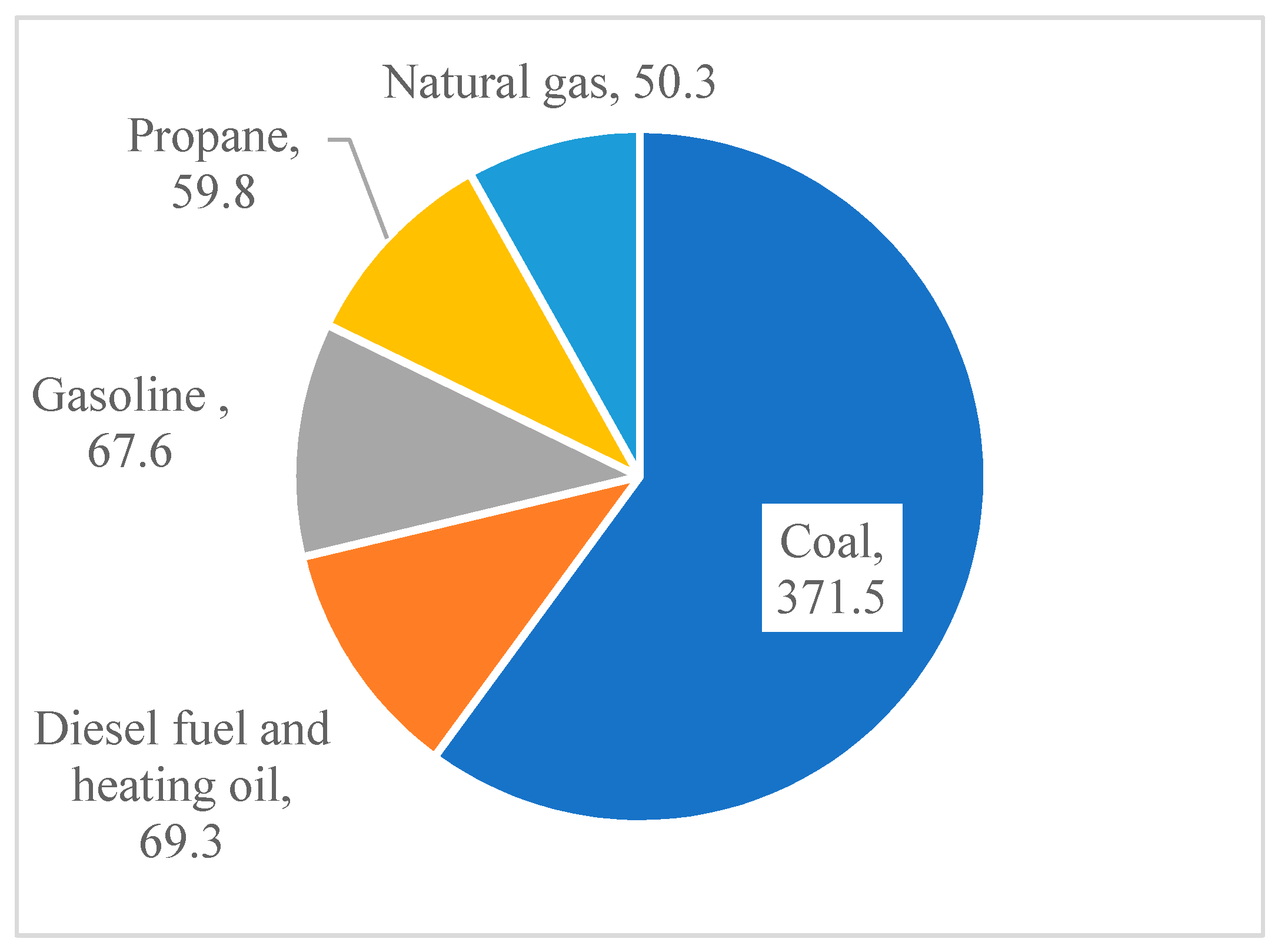
:1. Introduction
2. Methane-Hydrogen Blends
2.1. Methods for Hydrogen Production
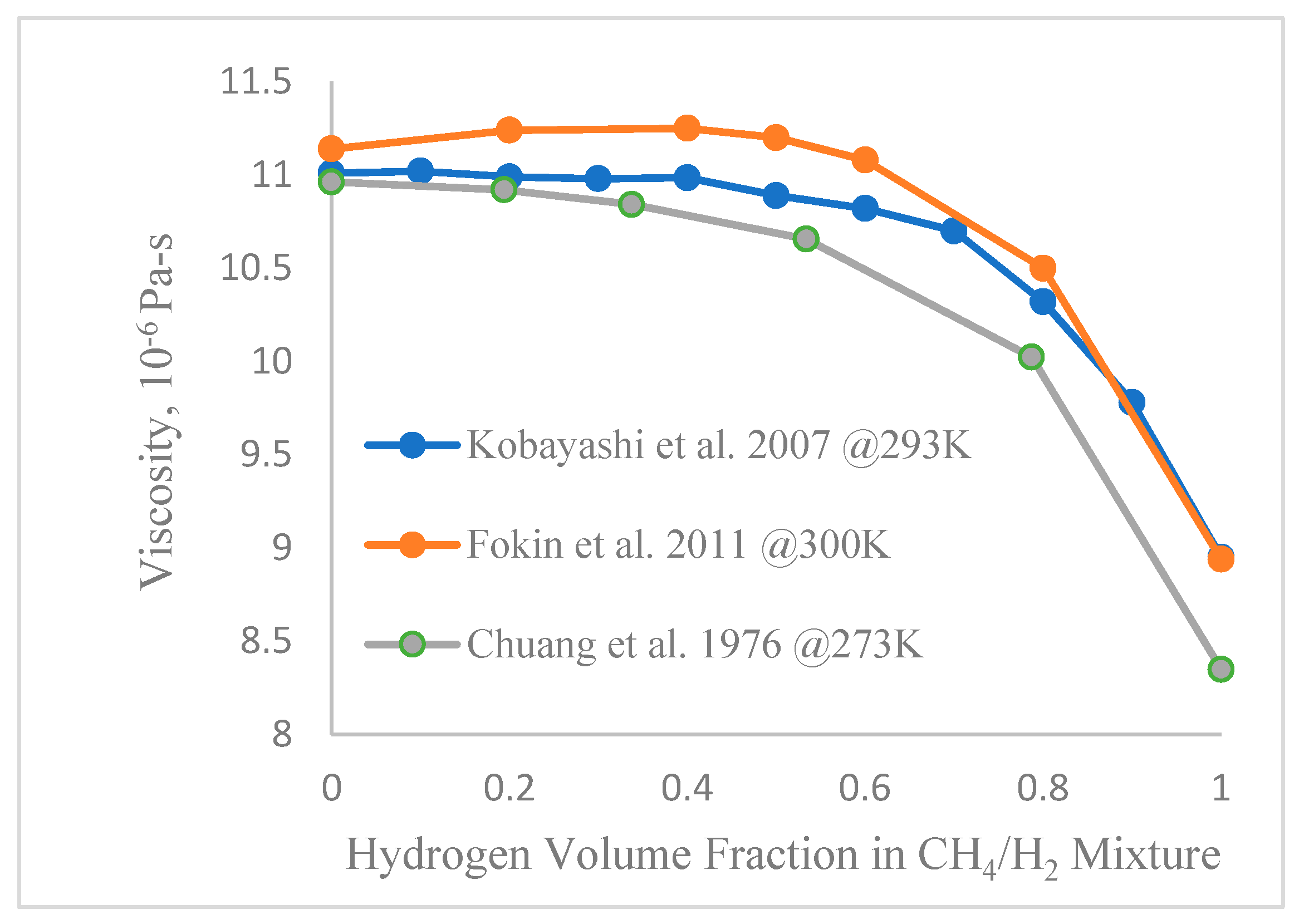
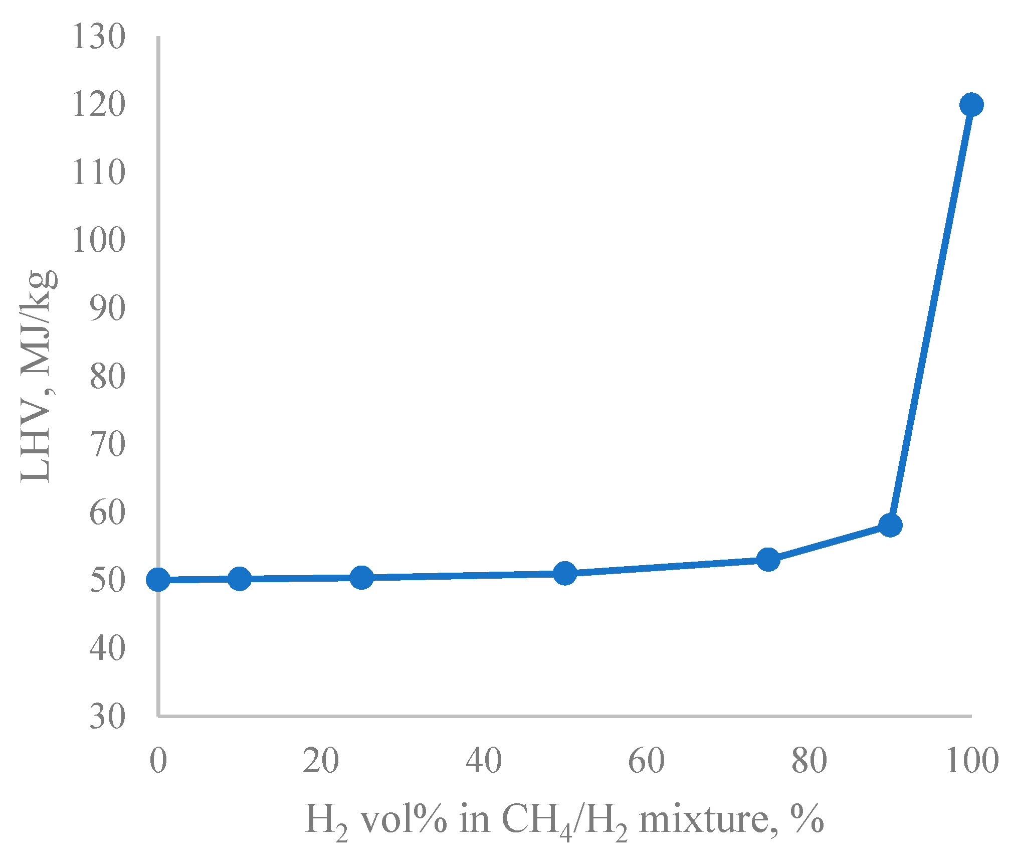
2.2. Properties of Methane-Hydrogen Blends
2.3. Benefits of Hydrogen Blending
2.4. End-Use Applications of Methane-Hydrogen Mixtures
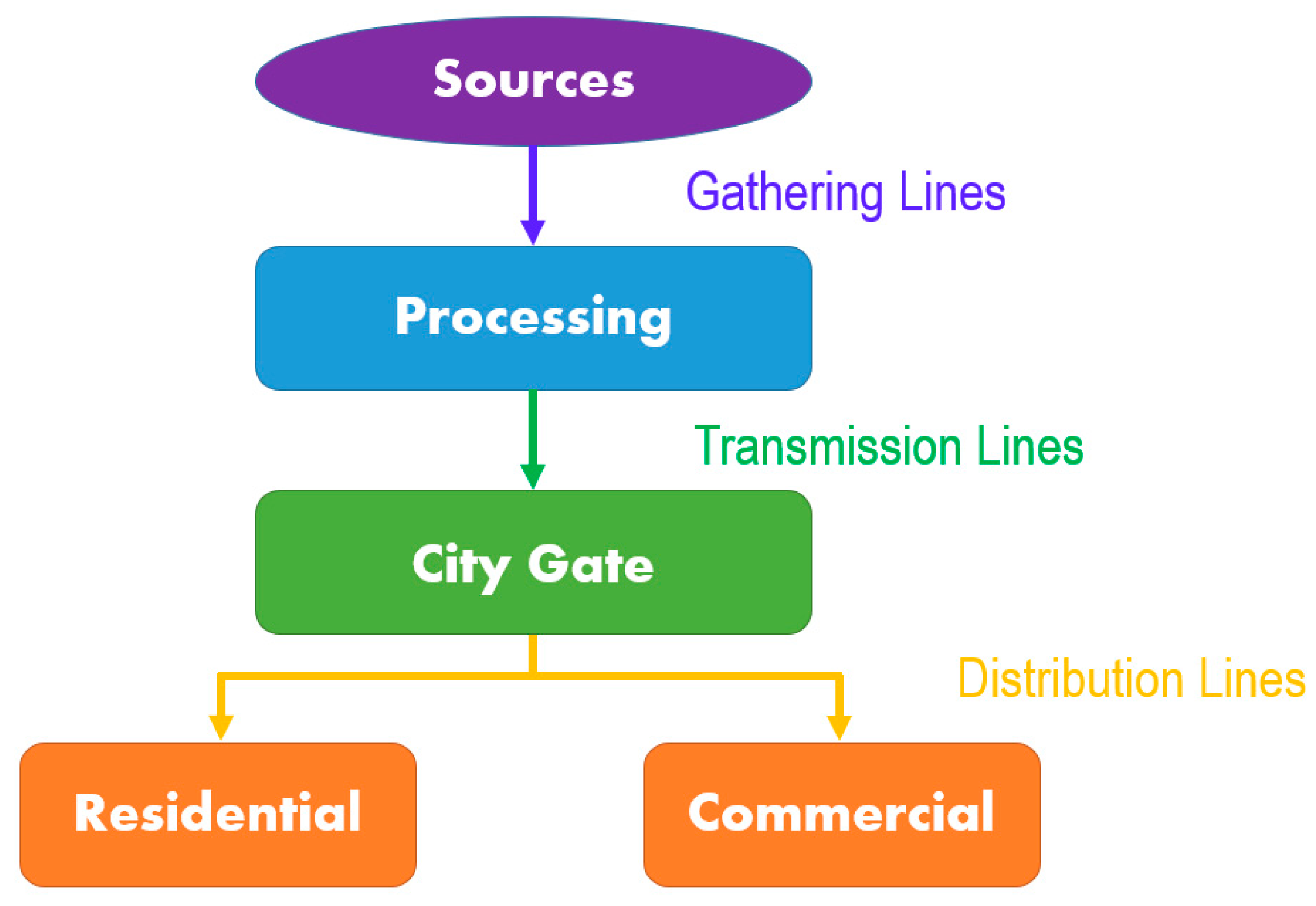
2.5. Gas Transportation Networks
2.5.1. Natural Gas Pipelines
2.5.2. Methane-Hydrogen Mixture Pipelines
2.5.3. Pure Hydrogen Delivery
2.6. Safety
2.6.1. Combustion Issues
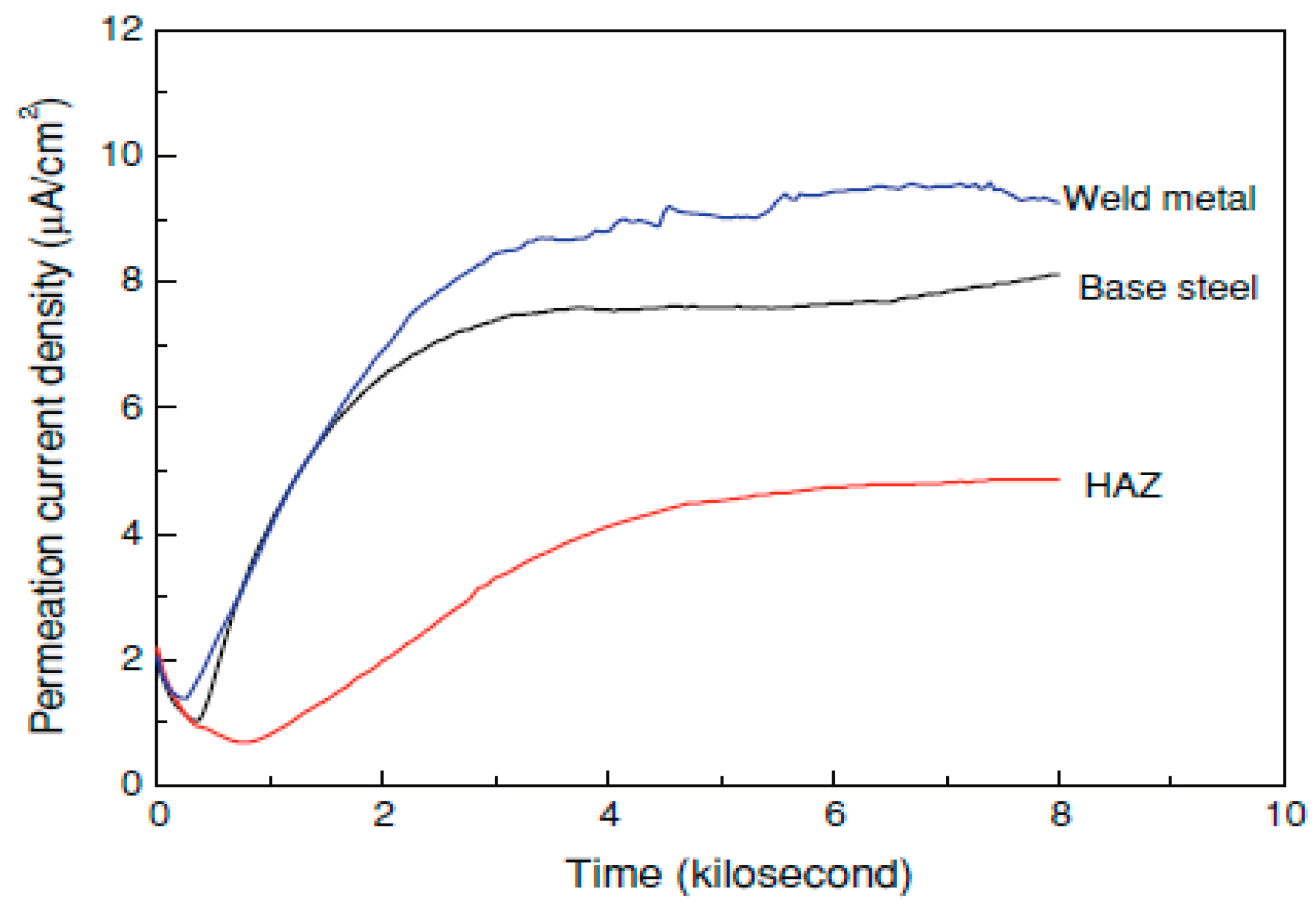
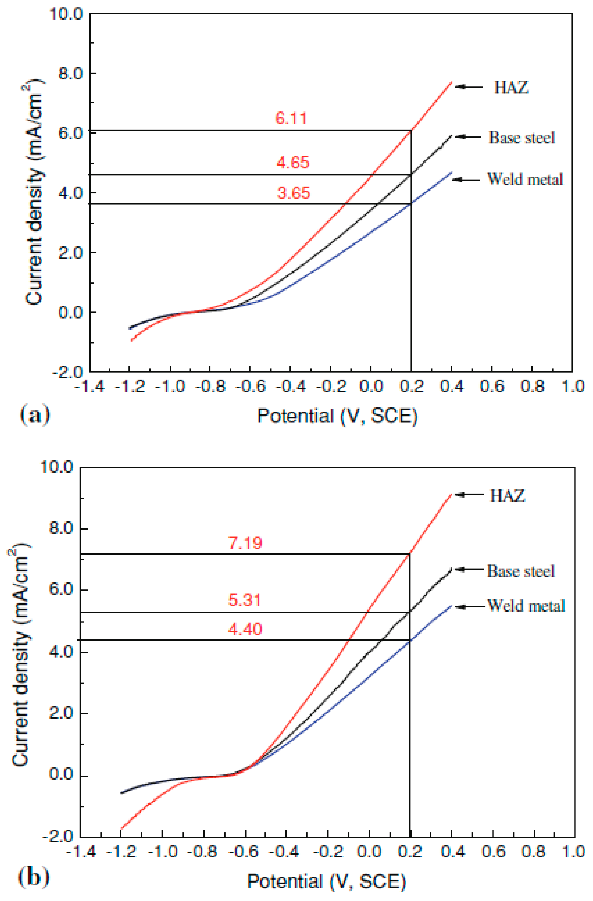
2.6.2. Materials Issues
3. Hydrogen Blending Projects
3.1. Hydrogen Blending Projects in the United Kingdom (UK)
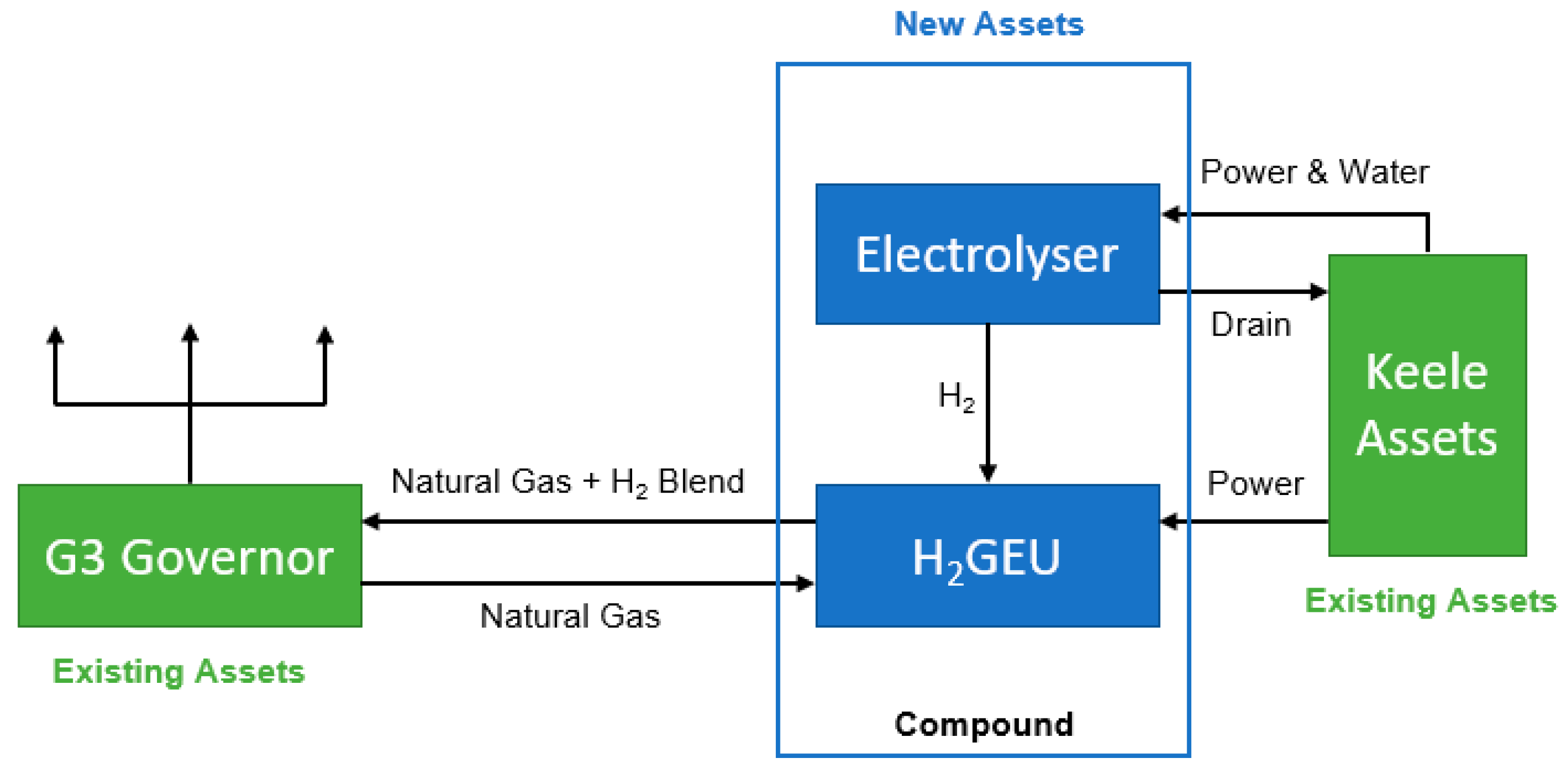
3.1.1. HyDeploy
3.1.2. Other UK Hydrogen Projects
3.2. Hydrogen Blending Projects in Europe
3.2.1. GRHYD
3.2.2. THyGA
3.2.3. WindGas Falkenhagen
3.3. Hydrogen Blending Projects in Australia
3.4. Hydrogen Blending Projects in Canada
3.5. Hydrogen Blending Projects in the United States

| Project | Country | Year | Blending Vol% | Trial/Project Size | Reference |
|---|---|---|---|---|---|
| HyDeploy | UK | 2019 | 20 | 1500 residentials | [74,75,76] |
| East Neuk Power | UK | 2020 | 20 | 15 GWh energy annually | [77] |
| Aberdeen Vision | UK | 2020 | 2–20 | 300 residentials | [78,79] |
| HyNet Northwest | UK | 2021 | 100 | 30 TWh energy annually | [80,81] |
| HyNTS Hydrogen Flow Loop | UK | 2021 | 30 | - | [82,83,84] |
| H21 | UK | 2018 | 100 | 6.4 TWh energy annually | [85] |
| Hy4Heat | UK | 2018 | 100 | - | [86,87,88] |
| HySpirit | UK | 2019 | 100 | - | [86,87,88] |
| Zero 2050 South Wale | UK | 2020 | 100 | - | [86,87,88] |
| Decarbonisation Pathway | UK | 2020 | 100 | - | [86,87,88] |
| GRHYD | France | 2014 | 20 | 200 residentials | [89] |
| THyGA | EU | 2019 | 10–100 | 100 residentials and commercials | [93,94] |
| WindGas Falkenhagen | Germany | 2013 | 2 | - | [95,96] |
| WindGas Hamburg | Germany | 2015 | 2 | - | [97] |
| HyP SA | Australia | 2021 | 5 | 700 residentials | [100,101] |
| HyP Gladstone | Australia | 10 | 800 residentials and industrials | [103] | |
| HyP Murry Valley | Australia | 2021 | 10 | 40,000 residentials | [103] |
| Jemena West Sydney | Australia | 2018 | 2 | 259 residentials | [103] |
| Fort Saskatchewan | Canada | 2020 | 5 | 2000 residentials | [105,106] |
| Cummins-Enbridge | Canada | 2018 | 2 | 3600 residentials | [106,107] |
| HyBlend | USA | 2021 | 1–30 | - | [109,110] |
| SoCalGas | USA | 2020 | 1–20 | - | [111] |
| Locations | Projects |
|---|---|
| West Australia | Clean Energy Innovation Park |
| Western Australian Feasibility Study | |
| South Australia | Hydrogen Park South Australia |
| Southeast Australia | Hydrogen Park Murray Valley |
| Australian Hydrogen Centre | |
| Northeast Australia | Hydrogen Park Gladstone |
| Locations | Projects |
|---|---|
| Eugene, Oregon | NW Natural |
| Salt Lake City, Utah | Dominion Energy |
| Southern California | SoCalGas and SDG&E |
| Austin, Texas | SoCalGas and ONE Gas |
| Twin Cities region, Minnesota | CenterPoint Energy |
| Ontario, Canada | Enbridge Gas |
| Stony Brook, New York | National Grid |
| Howell, New Jersey | New Jersey Resources |
4. Conclusions and Perspectives
Funding
Institutional Review Board Statement
Informed Consent Statement
Data Availability Statement
Acknowledgments
Conflicts of Interest
Abbreviations
| AGIG | Australian Gas Infrastructure Group |
| ANL | Argonne National Laboratory |
| API | American Petroleum Institute |
| ATEX | Atmospheric Explosion |
| BCC | Body-Centered Cube |
| BEIS | UK Department for Business, Energy & Industrial Strategy |
| BTU | British Thermal Unit. 1 BTU = 1055 J |
| CAI | Controlled Auto Ignition |
| CCS | Carbon Capture and Storage |
| CFD | Computational Fluid Dynamics |
| CLCPA | New York State’s Climate Leadership and Community Protection Act |
| DDT | Deflagration to Detonation Transition |
| ENA | Energy Networks Association |
| GREET | Greenhouse Gases, Regulated Emissions, and Energy Use in Transportation |
| HAZ | Heat-Affected Zone |
| HCATT | Hawaii Center for Advanced Transportation Technologies |
| HCEI | Hawaii Clean Energy Initiative |
| HE | Hydrogen Embrittlement |
| HIFLD | the United States Homeland Infrastructure Foundation-Level Data |
| H-Mat | Hydrogen Materials Compatibility Consortium |
| HNEI | Hawaii Natural Energy Institute |
| HSE | United Kingdom Health & Safety Executive |
| HSS | High Strength Steels |
| ICP-OES | Inductively Coupled Plasma—Optical Emission Spectrometry |
| I-GIT | Institute of Gas Innovation and Technology |
| LFL | Low Flammability Limit |
| LHV | Lower Heating Value. LHV(H2) = 120,000 kJ/kg. LHV(CH4) = 50,000 kJ/kg |
| NOx | Nitrogen Oxides |
| NREL | The United States National Renewable Energy Laboratory |
| NTS | National Transmission System |
| EERE | The United States Energy Efficiency and Renewable Energy office |
| EOS | Equation of State |
| EST | Energy Specific Toll |
| P2G | Power-to-Gas |
| PEM | Polymer Electrolyte Membrane |
| PE | Polyethylene |
| PNLL | Pacific Northwest National Laboratory |
| QRA | Quantitative Risk Assessment |
| SDG&E | San Diego Gas and Electric |
| SI Engine | Spark-Ignition Engine |
| SMR | Steam-Methane Reforming |
| SNG | Synthetic Natural Gas |
| SNL | The United States Sandia National Laboratories |
| SoCalGas | Southern California Gas Co. |
| SOEC | Solid Oxide Electrolysis Cell |
| SOx | Sulphur Oxides |
| SRK | Soave-Redlich-Kwong |
| RHEED | Reflection High-Energy Electron Diffraction |
| XPS | X-ray Photoelectron Spectroscopy |
References
- Masson-Delmotte, V.; Zhai, P.; Pirani, A.; Connors, S.L.; Pean, C.; Berger, S.; Caud, N.; Chen, Y.; Goldfarb, L.; Gomis, M.I.; et al. IPCC 2021: Summary for Policymakers. In Climate Change 2021: The Physical Science Basis; Contribution of Working Group I to the Sixth Assessment Report of the Intergovernmental Panel on Climate Change; Cambridge University Press: Cambridge, UK, 2021. [Google Scholar]
- How Much Carbon Dioxide is Produced When Different Fuels Are Burned? Available online: https://www.eia.gov/tools/faqs/faq.php?id=73&t=11 (accessed on 6 June 2021).
- U.S. Energy Facts Explained. Available online: https://www.eia.gov/energyexplained/us-energy-facts/ (accessed on 10 October 2020).
- Kothari, R.; Buddhi, D.; Sawhney, R.L. Comparison of environmental and economic aspects of various hydrogen production methods. Renew. Sustain. Energy Rev. 2008, 12, 553–563. [Google Scholar] [CrossRef]
- Nikolaidis, P.; Poullikkas, A. A comparative overview of hydrogen production processes. Renew. Sustain. Energy Rev. 2017, 67, 597–611. [Google Scholar] [CrossRef]
- Sun, X.; Xu, K.; Fleischer, C.; Liu, X.; Grandcolas, M.; Strandbakke, R.; Bjørheim, S.T.; Norby, T.; Chatzitakis, A. 2018 Earth-abundant electrocatalysts in proton exchange membrane electrolyzers. Catalysts 2018, 8, 657. [Google Scholar] [CrossRef] [Green Version]
- Dincer, I.; AlZahrani, A.A. 4.25 Elctrolyzers. In Comprehensive Energy Systems; Elsevier: Amsterdam, The Netherlands, 2018; Volume 4, pp. 985–1025. [Google Scholar] [CrossRef]
- Gunduz, S.; Deka, D.J.; Ozkan, U.S. Chapter three—Advances in high temperature electrocatalytic reaction of CO2 and H2O. In Advances in Catalysis; Academic Press: Cambridge, MA, USA, 2018; Volume 62, pp. 113–165. [Google Scholar]
- Energy.gov. Available online: https://www.energy.gov/articles/secretary-granholm-launches-hydrogen-energy-earthshot-accelerate-breakthroughs-toward-net (accessed on 25 April 2022).
- Lowesmith, B.J.; Hankinson, G.; Spataru, C.; Stobbart, M. Gas build-up in a domestic property following releases of methane/hydrogen mixtures. Int J. Hydrog. Energy 2009, 34, 5932–5939. [Google Scholar] [CrossRef] [Green Version]
- Kobayashi, Y.; Kurokawa, A.; Hirata, M. Viscosity measurement of hydrogen-methane mixed gas for future energy systems. J. Therm. Sci. Tech. 2007, 2, 236–244. [Google Scholar] [CrossRef] [Green Version]
- Fokin, L.R.; Kalashnikov, A.N.; Zolotukhina, A.F. Transport properties of mixtures of rarefied gases. Hydrogen-methane system. J. Eng. Phy. Thermophy 2011, 84, 1408–1420. [Google Scholar] [CrossRef]
- Chuang, S.Y.; Chappelear, P.S.; Kobayashi, R. Viscosity of methane, hydrogen, and four mixtures of methane and hydrogen from—100C to 0C at high pressures. J. Chem. Eng. Data 1976, 21, 403–411. [Google Scholar] [CrossRef]
- Marangon, A.; Carcassi, M.N. Hydrogen-methane mixtures: Dispersion and stratification studies. Int. J. Hydrog. Energy 2014, 39, 6160–6168. [Google Scholar] [CrossRef]
- Flekiewicz, M.; Kubica, G. An influence of methane/hydrogen proportion in fuel blend on efficiency of conversion energy in SI engine. J. KONES 2012, 19, 117–124. [Google Scholar] [CrossRef]
- Perry, R.H.; Green, D.W. Perry’s Chemical Engineers’ Handbook, 7th ed.; MCGRAW-HILL: New York, NY, USA, 1997; p. 631. [Google Scholar]
- Mariani, A.; Unich, A.; Minale, M. Combustion of hydrogen enriched methane and biogases containing hydrogenin a controlled auto-ignition engine. Appl. Sci. 2018, 8, 2667. [Google Scholar] [CrossRef] [Green Version]
- Melaina, M.W.; Antonia, O.; Penev, M. Blending Hydrogen into Natural Gas Pipeline Networks: A Review of Key Issues; National Renewable Energy Lab: Golden, CO, USA, 2013. [CrossRef] [Green Version]
- Obanijesu, E.O.; Barifcani, A.; Pareek, V.K.; Tade, M.O. Experimental study on feasibility of H2 and N2 as hydrate inhibitors in natural gas pipelines. J. Chem. Eng. Data 2014, 59, 3756–3766. [Google Scholar] [CrossRef]
- Najjar, Y. Alternative fuels for spark ignition engines. Open Fuels Energy Sci. J. 2009, 2, 1–9. [Google Scholar] [CrossRef] [Green Version]
- Chiesa, P.; Lozza, G.; Mazzocchi, L. Using hydrogen as gas turbine fuel. J. Eng. Gas Turbines Power 2005, 127, 73–80. [Google Scholar] [CrossRef] [Green Version]
- Shih, H.-Y.; Liu, C.-R. A computational study on the combustion of hydrogen/methane blended fules for a micro gas turbines. Int. J. Hydrog. Energy 2014, 39, 14103–15115. [Google Scholar] [CrossRef]
- Leicher, J.; Schaffert, J.; Cigarida, H.; Tali, E.; Burmeister, F.; Giese, A.; Albus, R.; Görner, K.; Carpentier, S.; Milin, P.; et al. The impact of hydrogen admixture into natural gas on residential and commercial gas appliances. Energies 2022, 15, 777. [Google Scholar] [CrossRef]
- Glanville, P.; Fridlyand, A.; Sutherland, B.; Liszka, M.; Zhao, Y.; Bingham, L.; Jorgensen, K. Impact of hydrogen/natural gas blends on partially premixed combustion equipment: NOx emission and operational performance. Energies 2022, 15, 1706. [Google Scholar] [CrossRef]
- Zhao, Y.; McDonell, V.; Samuelsen, S. Experimental assessment of the combustion performance of an oven burner operated on pipeline natural gas mixed with hydrogen. Int. J. Hydrog. Energy 2019, 44, 26049–26062. [Google Scholar] [CrossRef]
- Wagner, K.; Tiwari, P.; Swiegers, G.F.; Wallace, G.G. Alkaline fuel cells with novel gortex-based electrodes are powered remarkably efficiently by methane containing 5% hydrogen. Adv. Energy Mat. 2018, 8, 1702285. [Google Scholar] [CrossRef] [Green Version]
- Natural Gas Explained. Available online: https://www.eia.gov/energyexplained/natural-gas/natural-gas-pipelines.php (accessed on 10 October 2020).
- American Gas Association. Available online: https://www.aga.org/natural-gas/delivery/how-does-the-natural-gas-delivery-system-work-/ (accessed on 12 October 2020).
- HIFLD. Available online: https://hifld-geoplatform.opendata.arcgis.com/datasets/natural-gas-compressor-stations (accessed on 20 January 2021).
- Hafsi, Z.; Elaoud, S.; Akrout, M.; Hadj-Taïeb, E. Numerical approach for steady state analysis of hydrogen-natural gas mixtures flows in looped network. Arab. J. Sci. Eng. 2017, 42, 1941–1950. [Google Scholar] [CrossRef]
- Cadorin, M.; Morini, M.; Pinelli, M. Numerical analyses of high Reynolds number flow of high pressure fuel gas through rough pipes. Int. J. Hydrog. Energy 2010, 35, 7568–7579. [Google Scholar] [CrossRef]
- Tan, K.; Mahajan, D.; Venkatesh, T.A. Computational fluid dynamic modeling of methane-hydrogen mixture transportation in pipelines: Estimating energy costs. MRS Adv. 2022, 2022, 1–6. [Google Scholar] [CrossRef]
- Bainier, F.; Kurz, R. Impact of H2 blending of capacity and efficiency on a gas transport network. In Proceedings of the ASME Turbo Expo: Turbomachinergy Technical Conference and Exposition 9, Phoenix, AZ, USA, 17–21 June 2019. [Google Scholar]
- Abeysekera, M.; Wu, J.; Jenkins, N.; Rees, M. Steady state analysis of gas networks with distributed injection of alternative gas. Appl. Energy 2016, 164, 991–1002. [Google Scholar] [CrossRef] [Green Version]
- Cavana, M.; Mazza, A.; Chicco, G.; Leone, P. Electrical and gas networks coupling through hydrogen blending under increasing distributed photovoltaic generation. Appl. Energy 2021, 290, 116764. [Google Scholar] [CrossRef]
- Fiebig, C.; Hielscher, A.; Span, R.; Gulin, A.; Rickelt, S.; Schley, P. Gas quality tracking in distribution grids with SmartSim-application in complex and smeshed grids. In Proceedings of the International Gas Union Research Conference-IGRC, Copenhagen, Denmark, 17–19 September 2014. [Google Scholar]
- Dell’Isola, M.; Ficco, G.; Moretti, L.; Perna, A.; Candelaresi, D.; Spazzafumo, G. Impact of hydrogen injection on thermophysical properties and measurement reliability in natural gas network. E3S Web Conf. 2021, 312, 01004. [Google Scholar]
- Cavana, M.; Vaccariello, E.; Leone, P. Pressure management in smart gas networks for increasing hydrogen blending. E3S Web Conf. 2022, 334, 03003. [Google Scholar] [CrossRef]
- Quintino, F.M.; Nascimento, N.; Fernandes, E.C. Aspects of hydrogen and biomethane introduction in natural gas infrastructure and equipment. Hydrogen 2021, 2, 301–318. [Google Scholar] [CrossRef]
- Kong, M.; Feng, S.; Xia, Q.; Chen, C.; Pan, Z.; Gao, Z. Investigation of mixing behavior of hydrogen blended to natural gas in gas network. Sustainability 2021, 13, 4255. [Google Scholar] [CrossRef]
- Wang, G.; Ogden, J.M.; Nicholas, M.A. Lifecycle impacts of natural gas to hydrogen pathways on urban air quality. Int. J. Hydrog. Energy 2007, 32, 2731–2742. [Google Scholar] [CrossRef] [Green Version]
- Penev, M.; Zuboy, J.; Hunter, C. Economic analysis of a high-pressure urban pipeline concept (HyLine) for delivering hydrogen to retail fueling stations. Transp. Res. Part D 2019, 77, 92–105. [Google Scholar] [CrossRef]
- Shirvill, L.C.; Roberts, T.A.; Royle, M.; Willoughby, D.B.; Sathiah, P. Experimental study of hydrogen explosion in repeated pipe congestion—part 2: Effects of increase in hydrogen concentration in hydrogen-methane-air mixture. Int. J. Hydrog. Energy 2019, 44, 3264–3276. [Google Scholar] [CrossRef]
- Lowesmith, B.J.; Hankinson, G.; Johnson, D.M. Vapor cloud explosions in a long congested region involving methane/hydrogen mixtures. Process Saf. Environ. Prot. 2011, 89, 234–247. [Google Scholar] [CrossRef] [Green Version]
- Emami, S.D.; Rajabi, M.; Hassan CR, C.; Hamid MD, A.; Kasmani, R.M.; Mazangi, M. Experimental study on premixed hydrogen/air and hydrogen-methane/air mixtures explosion in 90 degree bend pipeline. Int. J. Hydrog. Energy 2013, 38, 14115–14120. [Google Scholar] [CrossRef]
- Di Sarli, V.; Di Benedetto, A. Laminar burning velocity of hydrogen-methane/air premixed flames. Int. J. Hydrog. Energy 2007, 32, 637–646. [Google Scholar] [CrossRef]
- Hu, E.; Huang, Z.; He, J.; Jin, C.; Zheng, J. Experimental and numerical study on laminar burning characteristics of premixed methane-hydrogen-air flames. Int. J. Hydrog. Energy 2009, 34, 4876–4888. [Google Scholar] [CrossRef]
- Di Sarli, V.; Di Benedetto, A.; Long, E.J.; Hargrave, G.K. Time-resolved particle image velocimetry of dynamic interactions between hydrogen-enriched methane/air premixed flames and toroidal vortex structures. Int. J. Hydrog. Energy 2012, 37, 16201–16213. [Google Scholar] [CrossRef] [Green Version]
- Di Sarli, V.; Di Benedetto, A. Effects of non-equidiffusion on unsteady propagation of hydrogen-enriched methane/air premixed flames. Int. J. Hydrog. Energy 2013, 38, 7510–7518. [Google Scholar] [CrossRef]
- Salzano, E.; Cammarota, F.; Di Benedetto, A.; Di Sarli, V. Explosion behavior of hydrogen-methane/air mixtures. J. Loss Prev. Process Ind. 2012, 25, 443–447. [Google Scholar] [CrossRef]
- Shen, X.; Xiu, G.; Wu, S. Experimental study on the exploration characteristics of methane/air mixtures with hydrogen addition. Appl. Therm. Eng. 2017, 120, 741–747. [Google Scholar] [CrossRef]
- Zhang, G.; Popov, B.N.; White, R.E. Hydrogen atom direct-entry mechanism into metal membranes. J. Electrochem. Soc. 1995, 142, 154–156. [Google Scholar] [CrossRef] [Green Version]
- Shirband, Z.; Shishesaz, M.R.; Ashrafi, A. Hydrogen degradation of steels and its related parameters, a review. Phase Transit. 2011, 84, 924–943. [Google Scholar] [CrossRef]
- Archakov, Y.I.; Grebeshkova, I.D. Natural of hydrogen embrittlement of steel. Metal. Sci. Heat Treat. 1985, 27, 555–562. [Google Scholar] [CrossRef]
- Ohaeri, E.; Eduok, U.; Szpunar, J. Hydrogen related degradation in pipeline steel: A review. Int. J. Hydrog. Energy 2018, 43, 14584–14617. [Google Scholar] [CrossRef]
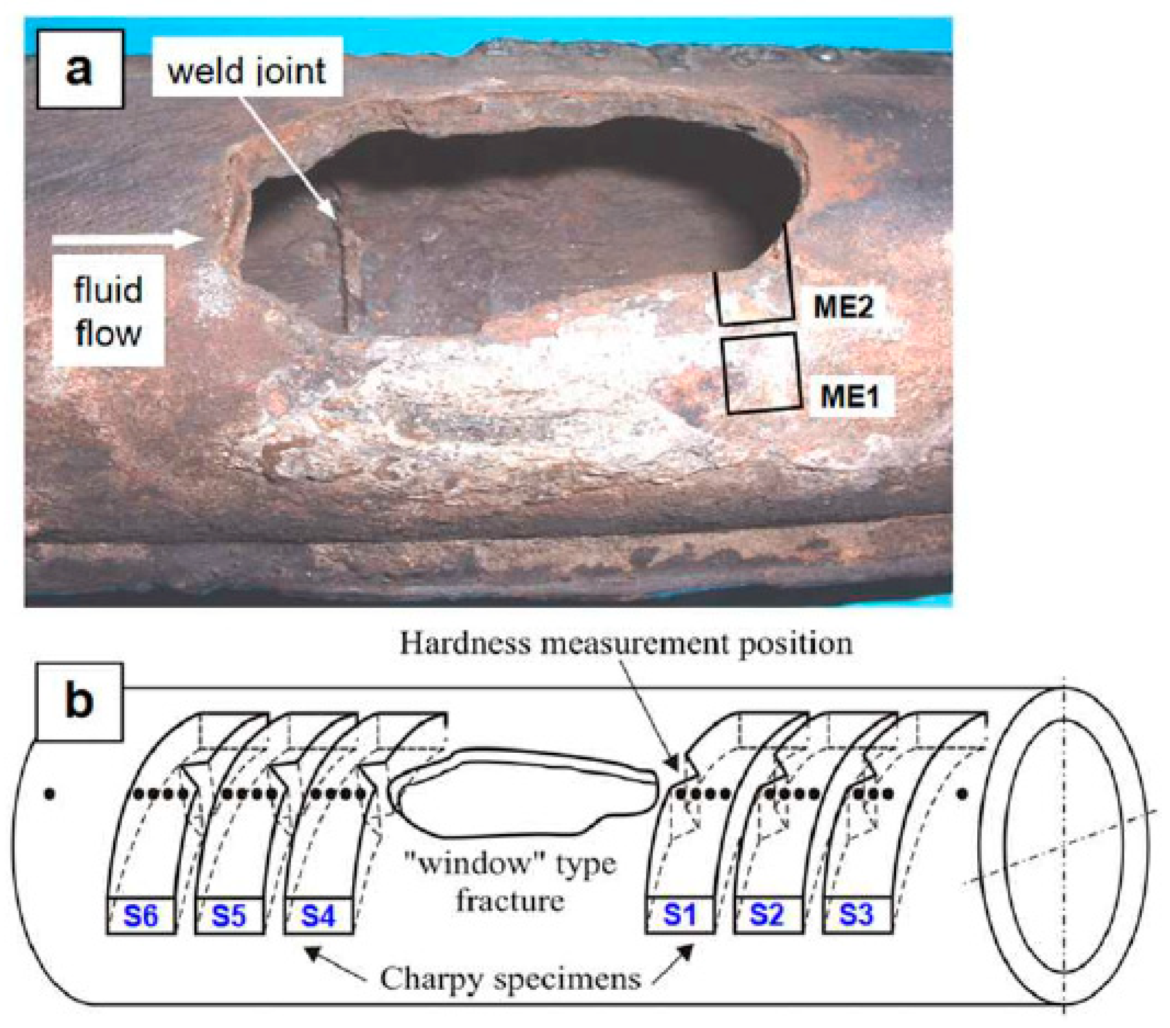
- Djukic, M.B.; Zeravcic, V.S.; Bakic, G.M.; Sedmak, A.; Rajicic, B. Hydrogen damage of steels: A case study and hydrogen embrittlement model. Eng. Fail. Anal. 2015, 58, 485–498. [Google Scholar] [CrossRef]
- Dadfarnia, M.; Sofronis, P.; Brouwer, J.; Sosa, S. Assessment of resistance to fatigue crack growth of natural gas line pipe steels carrying gas mixed with hydrogen. Int. J. Hydrog. Energy 2019, 44, 10808–10822. [Google Scholar] [CrossRef]
- Itsumi, Y.; Ellis, D.E. Electronic bonding characteristics of hydrogen in bcc iron: Part I. interstitials. J. Mater. Res. 1996, 11, 2206–2213. [Google Scholar] [CrossRef]
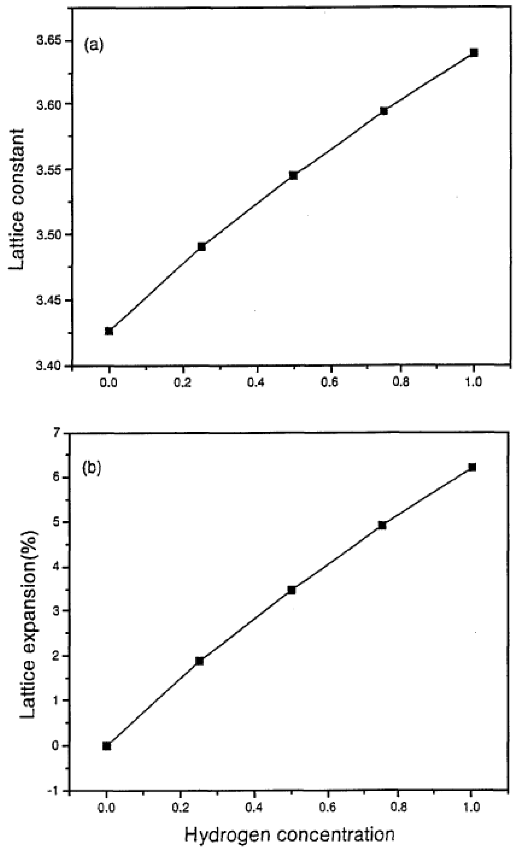
- Nash, G.; Choo, H.; Nash, P.; Daemen, L.L.; Bourke, M.A. Lattice dilation in a hydrogen charged steel, International Centre for Diffraction Data 2003. Adv. X-ray Anal. 2003, 46, 238–244. [Google Scholar]
- Yu, J.-Z.; Sun, Q.; Wang, Q.; Onose, U.; Akiyama, Y.; Kawazoe, Y. First-principles calculation on dissociation of hydrogen molecule in nickel. Mater. Trans. JIM 2000, 41, 1114. [Google Scholar] [CrossRef] [Green Version]
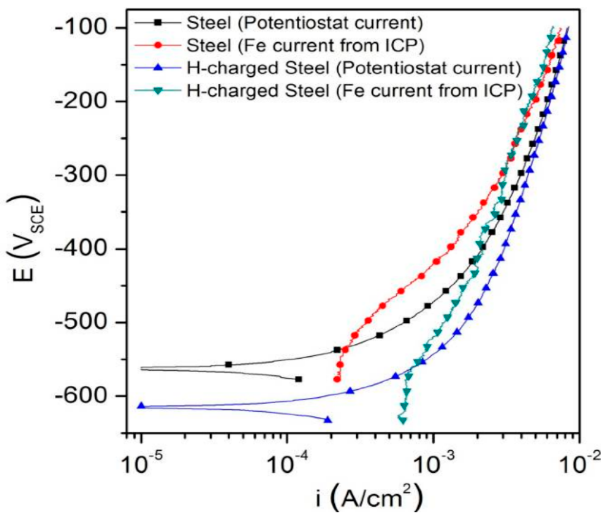
- Thomas, S.; Ott, N.; Schaller, R.F.; Yuwono, J.A.; Volovitch, P.; Sundararajan, G.; Medhekar, N.V.; Ogle, K.; Scully, J.R.; Birbilis, N. The effect of absorbed hydrogen on the dissolution of steel. Helyion 2016, 2, e00209. [Google Scholar] [CrossRef]
- Ningshen, S.; Mudali, U.K.; Amarendra, G.; Gopalan, P.; Dayal, R.K.; Khatak, H.S. Hydrogen effects on the passive film formation and pitting susceptibility of nitrogen containing type 316L stainless steels. Corros. Sci. 2006, 48, 1106–1121. [Google Scholar] [CrossRef]
- Michalska, J.; Chmiela, B.; Łabanowski, J.; Simka, W. Hydrogen damage in superaustenitic 904L stainless steels. J. Mater. Eng. Perform. 2014, 23, 2760–2765. [Google Scholar] [CrossRef] [Green Version]
- Takai, K.; Murakami, K.; Yabe, N.; Suzuki, H.; Hagihara, Y. Properties of thermal hydrogen desorption and substitution of high-pressure gas charging by electrolysis charging for inconel 625 and sus 316L. J. Jpn. Inst. Met. Mater. 2008, 72, 448–456. [Google Scholar] [CrossRef] [Green Version]
- Enomoto, M.; Cheng, L.; Mizuno, H.; Watanabe, Y.; Omura, T.; Sakai, J.I.; Yokoyama, K.I.; Suzuki, H.; Okuma, R. Hydrogen absorption into austenitic stainless steels under high-pressure gaseous hydrogen and cathodic charge in aqueous solution. Metall. Mater. Trans. E 2014, 1, 331–340. [Google Scholar] [CrossRef] [Green Version]
- Omura, T.; Suzuki, H.; Okamura, T.; Yamada, H.; Miwa, N.; Watanabe, Y.; Tada, M.; Saito, H.; Hayakawa, M.; Okuma, R.; et al. Hydrogen charging methods to low alloy steel simulating atmospheric and high pressure gaseous hydrogen environments. Tetsu Hagane J. Iron Steel Inst. Jpn. 2014, 100, 1289–1297. [Google Scholar] [CrossRef] [Green Version]
- Okamoto, G. Passive film of 18-8 stainless steel structure and its function. Corros. Sci. 1973, 13, 471–489. [Google Scholar] [CrossRef]
- Clayton, C.R.; Doss KG, K.; Wang, Y.F.; Warren, J.B.; Hubler, G.K. RHEED, AES and XPS studies of the passive films formed on ion implanted stainless steel. In Proceedings of the First Conference on Surface Modification by Ion Implantation, UMIST, Manchester, UK, 23–26 June 1981. [Google Scholar]
- Lu, Y.C.; Clayton, C.R.; Brooks, A.R. A bipolar model of the passivity of stainless steels—II. The influence of aqueous molybdate. Corros. Sci. 1989, 29, 863–880. [Google Scholar] [CrossRef]
- Clayton, C.R.; Lu, Y.C. A bipolar model of the passivity of stainless steels—III. The mechanism of MoO4(2-) formation and incorporation. Corros. Sci. 1989, 29, 881–898. [Google Scholar] [CrossRef]
- Pourbaix, M. Atlas of Electrochemical Equilibria in Aqueous Solutions, 2nd ed.; NACE International: Houston, TX, USA, 1974; p. 307. [Google Scholar]
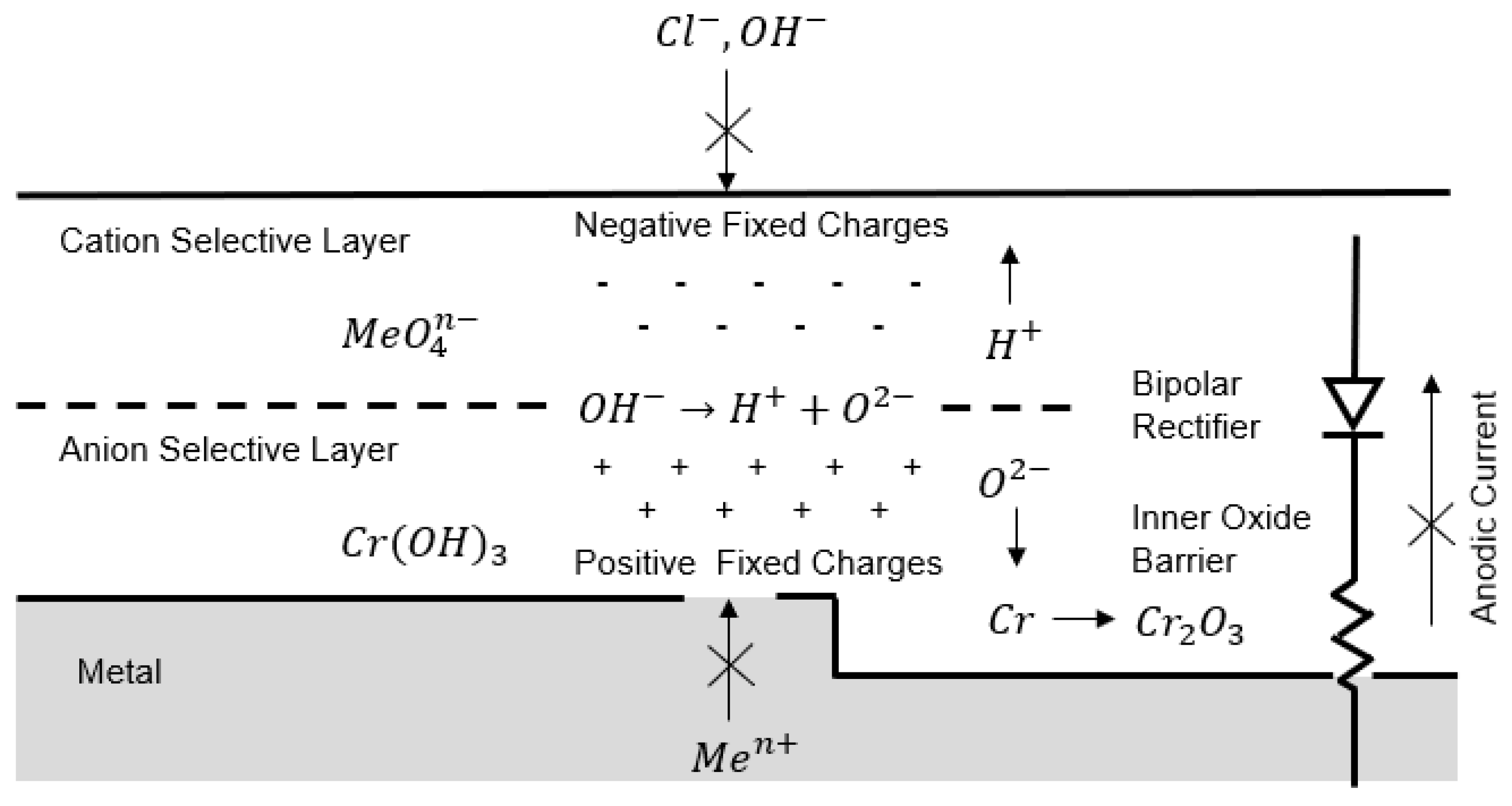
- Clayton, C.R.; Lu, Y.C. A bipolar model of the passivity of stainless steel. J. Electrochem. Soc. 1986, 133, 2465–2473. [Google Scholar] [CrossRef]
- Xue, H.B.; Cheng, Y.F. Hydrogen permeation and electrochemical corrosion behavior of the X80 pipeline steel weld. J. Mater. Eng. Perform. 2013, 22, 170–175. [Google Scholar] [CrossRef]
- LSE. Available online: https://climate-laws.org/geographies/united-kingdom/laws/climate-change-act-34405aa9-396e-4a78-a662-20cad9696365 (accessed on 12 October 2020).
- Wakefield, J.; Kassem, M. Improving site access verification and operator safety in smart and sustainable assets: A pilot study in a UK decarbonization project. In Proceedings of the 37th CIB W78 Information Technology for Construction Conference, Sao Paulo, Brazil, 18-20 August 2020; pp. 374–384. [Google Scholar]
- Isaac, T. HyDeploy: The UK’s first hydrogen blending deployment project. Clean Energy 2019, 3, 114–125. [Google Scholar] [CrossRef] [Green Version]
- SGN. Available online: https://www.sgn.co.uk/about-us/future-of-gas/hydrogen/east-neuk-power-hydrogen (accessed on 10 January 2021).
- SGN. Available online: https://sgn.co.uk/about-us/future-of-gas/hydrogen/aberdeen-vision (accessed on 10 January 2021).
- Energy Voice. Available online: https://www.energyvoice.com/renewables-energy-transition/183462/aberdeen-vision-for-pioneering-hydrogen-from-gas-project/ (accessed on 12 January 2021).
- Hynet North West. Available online: https://hynet.co.uk/ (accessed on 2 February 2021).
- Hydrogen View. Available online: https://www.h2-view.com/story/hynet-hydrogen-production-plant-the-uks-first-large-scale-low-carbon-hydrogen-facility/ (accessed on 2 February 2021).
- HyNTS: Hydrogen in the NTS. Available online: https://www.nationalgrid.com/uk/gas-transmission/document/133841/download (accessed on 3 February 2021).
- [9 November] Landmark Study Reviews Current Technology That Could Help Roll out Hydrogen across the UK Gas Network. Available online: https://www.nationalgrid.com/9-november-landmark-study-reviews-current-technology-could-help-roll-out-hydrogen-across-uk-gas (accessed on 12 October 2020).
- ofgem. Available online: https://www.ofgem.gov.uk/publications/hynts-futuregrid-phase-1-national-grid-gas-transmission (accessed on 20 October 2020).
- H21. Available online: https://h21.green/about/ (accessed on 12 January 2021).
- EMEC. Available online: https://www.emec.org.uk/projects/hydrogen-projects/hyspirits/ (accessed on 12 January 2021).
- Zero 2050. Available online: https://www.zero2050.co.uk/ (accessed on 12 January 2021).
- Network. Available online: https://networks.online/gas/ena-launches-new-gas-grid-decarbonisation-project/ (accessed on 12 October 2020).
- GRHYD. Available online: https://www.engie.com/en/businesses/gas/hydrogen/power-to-gas/the-grhyd-demonstration-project (accessed on 12 October 2020).
- Alliat, I. The first hythane refueling station in France: A successful demonstration. In Proceedings of the International Gas Union Research Conference, Korea, Seoul, 19–21 October 2011. [Google Scholar]
- Gouvernement. Available online: https://www.gouvernement.fr/en/climate-plan (accessed on 22 January 2021).
- European Comission. Available online: https://ec.europa.eu/clima/eu-action/european-green-deal/2030-climate-target-plan_en (accessed on 22 January 2021).
- THyGA. Available online: https://thyga-project.eu/about-thyga/ (accessed on 22 January 2021).
- Blanchard, L.; Briottet, L. Non-Combustion Related Impact of Hydrogen Admixture—Material Compatibility. THyGA Project 2020. Available online: https://www.h2knowledgecentre.com/content/conference295 (accessed on 11 May 2022).
- Green Car Congress. Available online: https://www.greencarcongress.com/2018/05/20180513-falkenhagen.html (accessed on 4 February 2021).
- Power. Available online: https://www.powermag.com/windgas-falkenhagen-pioneering-green-gas-production/ (accessed on 4 February 2021).
- H2 International. Available online: https://www.h2-international.com/2016/02/04/windgas-project-in-hamburg-reitbrook-in-operation/ (accessed on 4 February 2021).
- Reuters. Available online: https://www.reuters.com/business/energy/australia-starts-piping-hydrogen-gas-blend-into-homes-2021-05-19/ (accessed on 5 February 2021).
- AGIG. Available online: https://www.agig.com.au/hydrogen-park-south-australia (accessed on 5 February 2021).
- AGIG. Available online: https://www.agig.com.au/renewable-gas (accessed on 5 February 2021).
- Federal Ministry of Finance. Available online: https://www.bundesfinanzministerium.de/Content/EN/Standardartikel/Topics/Priority-Issues/Climate-Action/2019-09-19-climate-action-programme-2030.html (accessed on 1 March 2021).
- Australian Government Department of Industry, Science, Energy and Reseources. Available online: https://www.industry.gov.au/data-and-publications/technology-investment-roadmap-first-low-emissions-technology-statement-2020 (accessed on 1 March 2021).
- Australian Government Transparency Portal. Available online: https://www.transparency.gov.au/annual-reports/australian-renewable-energy-agency/reporting-year/2018-2019-25 (accessed on 1 March 2021).
- Government of Canada. Available online: https://www.canada.ca/en/services/environment/weather/climatechange/climate-plan/net-zero-emissions-2050/canadian-net-zero-emissions-accountability-act.html (accessed on 1 March 2021).
- ATCO. Available online: https://www.atco.com/en-ca/projects/fort-saskatchewan-hydrogen-blending-project.html (accessed on 1 March 2021).
- NGI. Available online: https://www.naturalgasintel.com/canadian-utilities-beginning-hydrogen-energy-field-tests/ (accessed on 1 March 2021).
- Cummins. Available online: https://www.cummins.com/news/2020/12/22/cummins-enbridge-project-brings-large-scale-hydrogen-blending-north-america (accessed on 1 March 2021).
- Hawaii Gas. Available online: https://www.hawaiigas.com/clean-energy/hydrogen/ (accessed on 1 March 2021).
- NREL. Available online: https://www.nrel.gov/news/program/2020/hyblend-project-to-accelerate-potential-for-blending-hydrogen-in-natural-gas-pipelines.html (accessed on 1 March 2021).
- PR Newswire. Available online: https://www.prnewswire.com/news-releases/socalgas-and-sdge-announce-groundbreaking-hydrogen-blending-demonstration-program-to-help-reduce-carbon-emissions-301178982.html (accessed on 1 March 2021).
- California Air Resources Board. Available online: https://ww2.arb.ca.gov/our-work/programs/cap-and-trade-program/about (accessed on 11 May 2022).
- Ewan, J.M. Hawaii Renewable Hydrogen Program: 2010-2020 Final Report. State of Hawaii 2011. Available online: https://www.hnei.hawaii.edu/projects/#hydro (accessed on 11 May 2022).
- The Business Journals. Available online: https://www.bizjournals.com/pacific/news/2016/12/02/hawaii-among-top-states-in-u-s-for-hydrogen-fuel.html (accessed on 1 March 2021).
- McCormick, M.D. The Hydrogen Race. American Gas Magazine. April 2021. Available online: https://www.aga.org/news/american-gas-magazine/past-issues/ (accessed on 12 May 2022).


| Natural Gas | Biogas 1 | Biogas 2 | CH4/H2 | ||
|---|---|---|---|---|---|
| CH4 comp. | [% v/v] | 82.5 | 60.0 | 40.0 | 90.0 |
| CO2 comp. | [% v/v] | 1.0 | 40.0 | 60.0 | 0 |
| H2 comp. | [% v/v] | 0 | 0 | 0 | 10.0 |
| LHV | [kJ/kg] | 47,351 | 17,627 | 9745 | 49,258 |
| EST | [m−1] | 1.47 × 10⁻⁶ | 1.80 × 10⁻⁶ | 1.98 × 10⁻⁶ | 2.86 × 10⁻⁶ |
Publisher’s Note: MDPI stays neutral with regard to jurisdictional claims in published maps and institutional affiliations. |
© 2022 by the authors. Licensee MDPI, Basel, Switzerland. This article is an open access article distributed under the terms and conditions of the Creative Commons Attribution (CC BY) license (https://creativecommons.org/licenses/by/4.0/).
Share and Cite
Mahajan, D.; Tan, K.; Venkatesh, T.; Kileti, P.; Clayton, C.R. Hydrogen Blending in Gas Pipeline Networks—A Review. Energies 2022, 15, 3582. https://doi.org/10.3390/en15103582
Mahajan D, Tan K, Venkatesh T, Kileti P, Clayton CR. Hydrogen Blending in Gas Pipeline Networks—A Review. Energies. 2022; 15(10):3582. https://doi.org/10.3390/en15103582
Chicago/Turabian StyleMahajan, Devinder, Kun Tan, T. Venkatesh, Pradheep Kileti, and Clive R. Clayton. 2022. "Hydrogen Blending in Gas Pipeline Networks—A Review" Energies 15, no. 10: 3582. https://doi.org/10.3390/en15103582