
Resiliency Analysis of Hybrid Energy Systems within Interconnected Infrastructures


1
Faculty of Energy Systems and Nuclear Science, Ontario Tech University (UOIT), Oshawa, ON L1G 0C5, Canada
2
Faculty of Engineering and Applied Science, Ontario Tech University (UOIT), Oshawa, ON L1G 0C5, Canada
Energies 2021, 14(22), 7499; https://doi.org/10.3390/en14227499
Submission received: 25 October 2021
/
Revised: 1 November 2021
/
Accepted: 5 November 2021
/
Published: 10 November 2021
(This article belongs to the Collection Feature Papers in Energy, Environment and Well-Being)
Abstract
:There are world tendencies to implement interconnected infrastructures of energy-water-waste-transportation-food-health-social systems to enhance the overall performance in normal and emergency situations where there are multiple interactions among them with possible conversions and improved efficiencies. Hybrid energy systems are core elements within interconnected infrastructures with possible conversions among electricity, thermal, gas, hydrogen, waste, and transportation networks. This could be improved with storage systems and intelligent control systems. It is important to study resiliency of hybrid energy systems within interconnected infrastructures to ensure reduced risks and improved performance. This paper presents framework for the analysis of resiliency layers as related to protection layers. Case study of hybrid energy system as integrated with water, waste, and transportation infrastructures is presented where different resiliency and protection layers are assessed. Performance measures are modeled and evaluated for possible interconnection scenarios with internal and external factors that led to resiliency demands. Resiliency layers could trigger protection layers under certain conditions, which are evaluated to achieve high performance hybrid energy systems within interconnected infrastructures. The proposed approach will support urban, small, and remote communities to achieve high performance interconnected infrastructures for normal and emergency situations.
1. Introduction
Smart cities offer the occupants of each community quality of life and wellbeing in terms of community development, economy, health, food, transportation, social, safety, security, and education. This is important for normal and emergency situations such as extreme weather conditions. One important aspect of community development is robust and efficient technological infrastructures with interconnected infrastructures that can assure real time interactions among energy, water-waste-transportation-food-health-social systems [1]. There are couplings and dependencies among energy, water, waste, transportation, food, health, and social systems. Food systems will include systems related to overall food lifecycle from resources till utilization and recycle. Similarly, health systems are related to health lifecycle from resources till usage in community applications for both human and animals. Social systems are important to support social activities, in terms of interactions, cultural, and community related activities. There are potential conversions among these systems which will impact the couplings and integration among these interconnected systems [2]. The accurate analysis of the couplings among these systems will ensure optimum overall performance while considering interactions among these systems.
Hybrid energy systems (HES) includes renewable energy resources from wind, solar, geothermal, as well as energy storage from electric storage, thermal storage, and gas or hydrogen storage. Typically, HES will be linked to electric, thermal, and gas loads with intelligent control and protection to ensure smooth operation and planning in view of different load profiles and energy demand requirements [3,4]. HES are essential to be integrated within interconnected infrastructures from water, waste, transportation, food, health, and social systems.
With the integration among hybrid energy systems within interconnected infrastructures it increases the needs for protection to reduce risks to each system while maintaining interactions with other systems [5]. There is a lack of protection analysis for integrated systems, where individual systems could be protected with safety systems, however, for integrated systems there might be impacts from one system to another, which require detailed analysis for fault propagation and risk estimation to achieve effective prevention and mitigation measures. The protection analysis for HES is still limited to typical power protection, while detailed analysis of integrated electric, thermal, and gas systems are not well established.
Resiliency of a given system is its ability to resist and overcome any challenge in terms of stresses/losses of facility, infrastructure, human, health, environment, production, reputation, or profits, and the ability to bounce back effectively with acceptable performance in reasonable response time [6,7,8]. There are number of attempts to develop methods for resiliency analysis such as qualitative studies to understand best practices of resiliency. Other techniques for quantitative resiliency analysis based on probabilistic analysis to meet system performance [9]. However, these techniques did not discuss response time to return to normal operation and the gap between ideal performance and the performance where system is returned to after resiliency actions. Moreover, most of these techniques did not integrate resiliency actions with design, control, and protection [10]. Data analytics techniques helped to support the analysis of hybrid energy systems while linking performance measures [11].
The analysis of design and operation scenarios of interconnected systems while considering HES are not well covered in literature. It is important to discuss design and operation scenarios and control strategies when studying resiliency where resiliency demands will be clarified and could be linked to potential resiliency actions and related systems [12]. Moreover, there is a lack of studying resiliency with respect to overall performance of interconnected systems, while considering performance modeling in view of possible disturbances that lead to resiliency demands and performance after resiliency actions. Furthermore, energy management techniques are potential to discuss resiliency within management schemes [13].
An integrated theoretical approach of modeling changes of a given system opportunity, cause, and purpose are described by Nicholas Georgescu-Roegen [14]. This is a useful approach to be used to evaluate resiliency of a given system.
The analysis of different initiating triggers, causes, consequences, and the proposed resiliency layers are explained in this paper and compared with the previous work to show a comprehensive model for both individual and interconnected systems.
2. HES within Interconnected Infrastructures
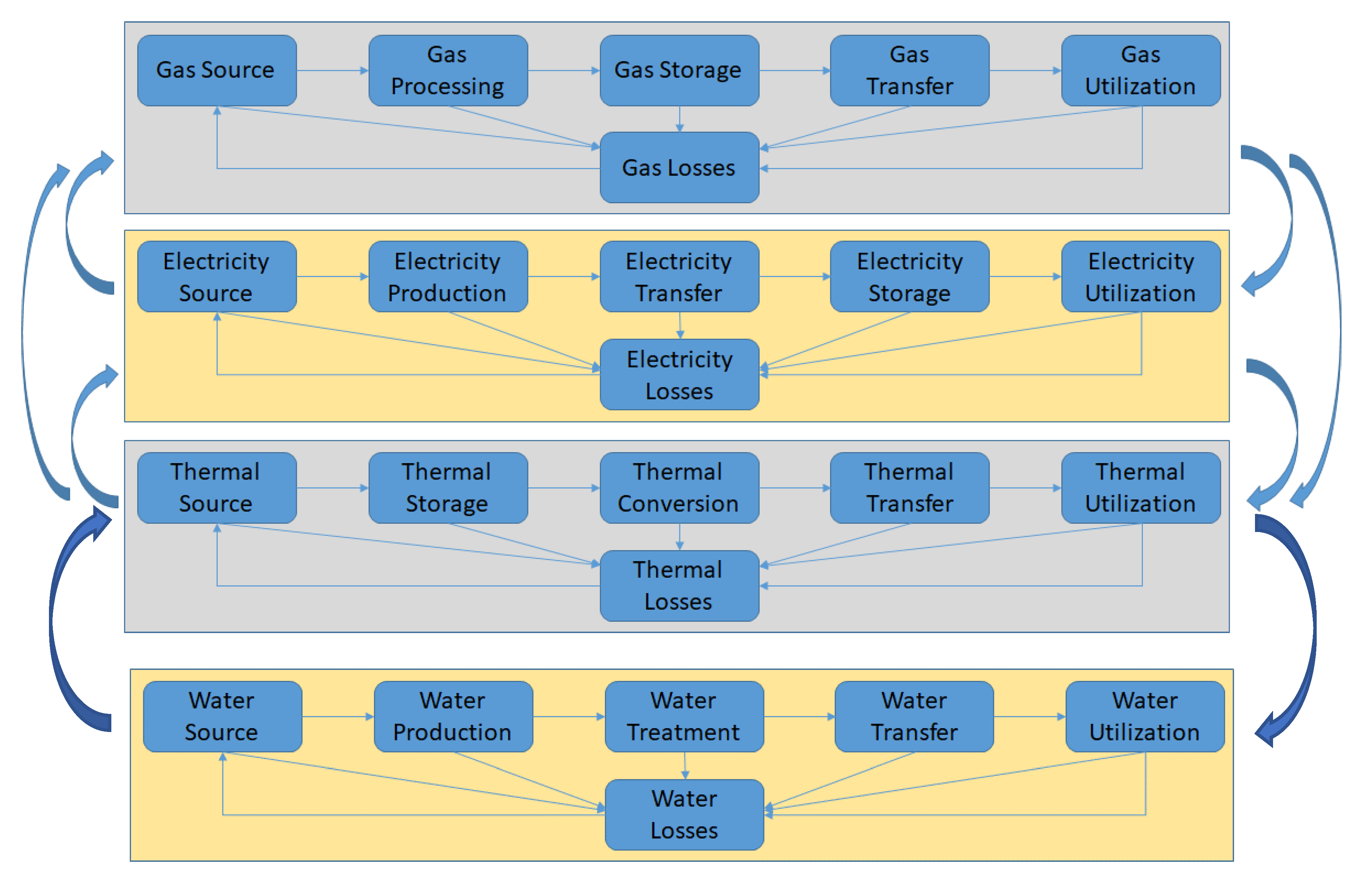
In modern smart cities, it is important to ensure interconnections among systems with real time analysis and interactions among state or process variables from each system. Figure 1 shows an overview of possible interconnections among energy, water, transportation, waste, food, health, and social systems via interfaces. HES are integrated within these interconnected systems where loads, storage, and generation components are linked.
In order to understand the interconnection mechanisms among different domains, an example of energy-water is used, as shown in Figure 2.
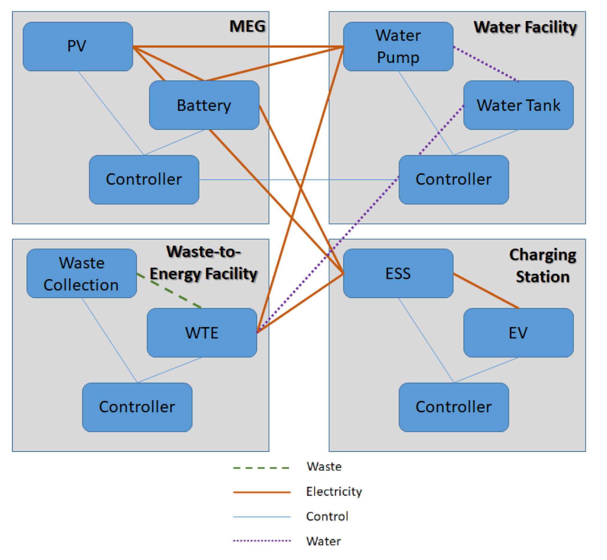
In order to illustrate HES within interconnected infrastructures, Figure 3 shows an example of hybrid energy system with microgrid (MG), water facility, waste-to-energy facility, and fast charging station for transportation electrification. The interactions among these systems are illustrated as energy, water, control, and waste lines. The resiliency analysis of such interconnected systems will be achieved via the study of propagation of deviations and events among different systems. The resiliency demands will be analyzed based on disturbances of set of state variables in interface ports among these systems with the required conversions.
The target resiliency analysis should address resiliency performance requirements among HES and the interconnected infrastructures from water, transportation, and waste. The following section will discuss the proposed resiliency performance analysis framework.
The proposed interface design [1] will allow mapping process variables and the coupling among them where resiliency will be measured and improved. The interface ports will allow local coupling analysis among electricity, thermal, gas, with water, transportation, waste, and other infrastructures. Elements within water networks, such as pumps, tanks, and treatment facilities will have interfaces that reflect internal coupling with energy, water, and other relevant parameters such as material, thermal, transport, data, social, or policy, as shown in Figure 4. The resiliency analysis will include resiliency coupling among these interfaces.
3. Proposed Resiliency Analysis Framework
The proposed resiliency analysis is based on defining independent resiliency layers, which is explained in the following section.
3.1. Independent Resiliency Layers
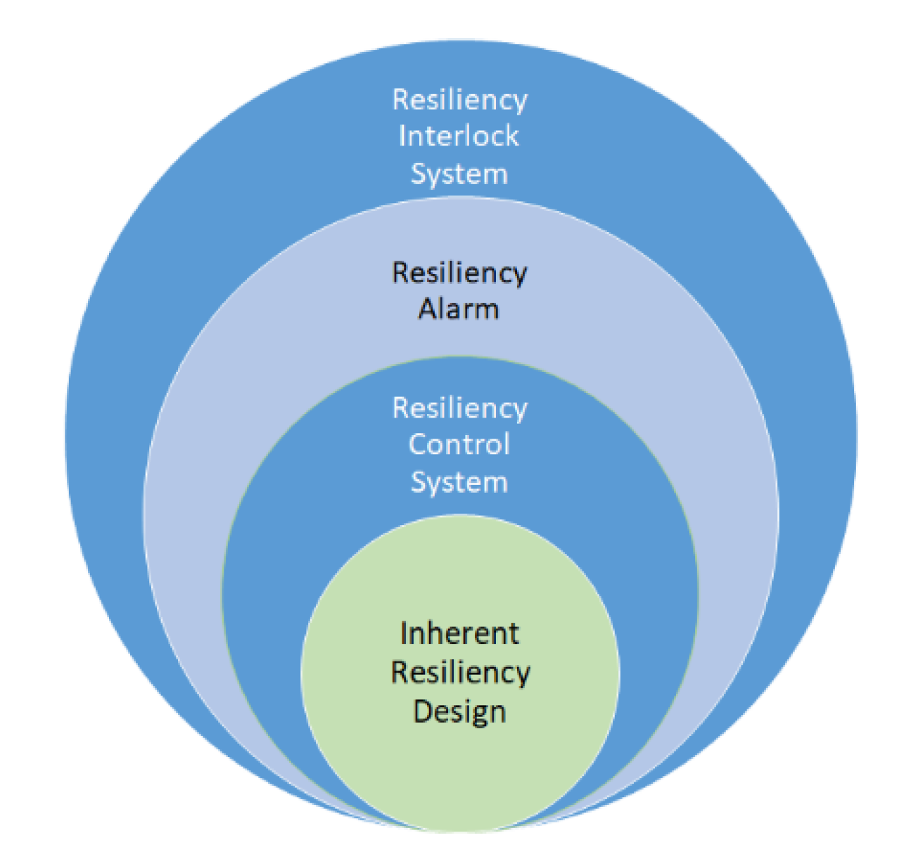
The following are the main four categories of resiliency layers, which are described in Figure 5, as follows:
- Inherence resiliency design (IRD);
- Resiliency control system (RCS);
- Resiliency alarms management (RAM);
- Resiliency interlock systems (RIS).
Figure 5.
Independent resiliency layers.

3.1.1. Inherent Resiliency Design (IRD)
Similar to inherent safety, inherent resiliency design includes design configuration and sizing of cogeneration, energy storage, and response time to start-stop. These features are considered as part of the design of HES. During the design, these features will be evaluated to ensure inherent resiliency. For example, availability of natural heat sources with thermal storage within HES to support increased thermal demand due to sever or elongated cold weather.
3.1.2. Resilient Control System (RCS)
Similar to the main function of basic process control system (BPCS) that will ensure process is within control limits, RCS will ensure that process is within resiliency limits, which are defined as the limits in which resiliency control function should be activated. Typically, the resiliency control limits are different from control limits but still located within safety limits, and defined using simulation and best practices where resiliency demand is triggered. RCS includes sensors, resiliency control logic solver, and actuators, and will function based on resiliency and fault tolerant control strategies in case of resiliency demand events. For example, in case energy supply drops to lower resiliency control limit, control action will be triggered to increase supply from energy storage, or conversion with cogeneration.
3.1.3. Resiliency Alarm Management (RAM)
Resiliency alarm management will be developed to alert system operators with potential resiliency actions based on alarm settings. Typically, process control alarms are defined as Low and High, while critical alarms are defined as Low-Low and High-High where operators will be alerted for critical actions. Similarly, resiliency alarms could be defined as Resiliency Low, Resiliency High, and critical resiliency alarms could be defined as Resiliency Low-Low and Resiliency High-High. Resiliency actions could be to tune cogeneration, energy storage, energy conversion systems as per matching load and demand relation.
3.1.4. Resiliency Interlock Systems (RIS)
Similar to safety instrumented (or interlock) systems, resiliency interlock systems (RIS) will automatically activate resiliency action and sub-system such as load, supply, storage, or co-generation systems. The use of RIS will be needed with critical loads where response time is small, less than alarm response time, i.e., time for the operator to take action based on alarm.
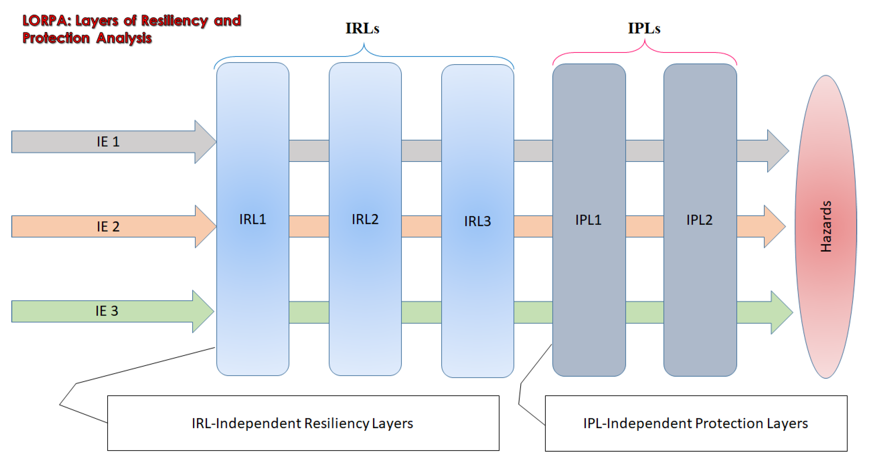
The integrated resiliency and protection layers are presented in Figure 6, where different initiating events could be controlled with resiliency layers and/or protection layers depending on process conditions and target performance.
4. Resiliency System Design
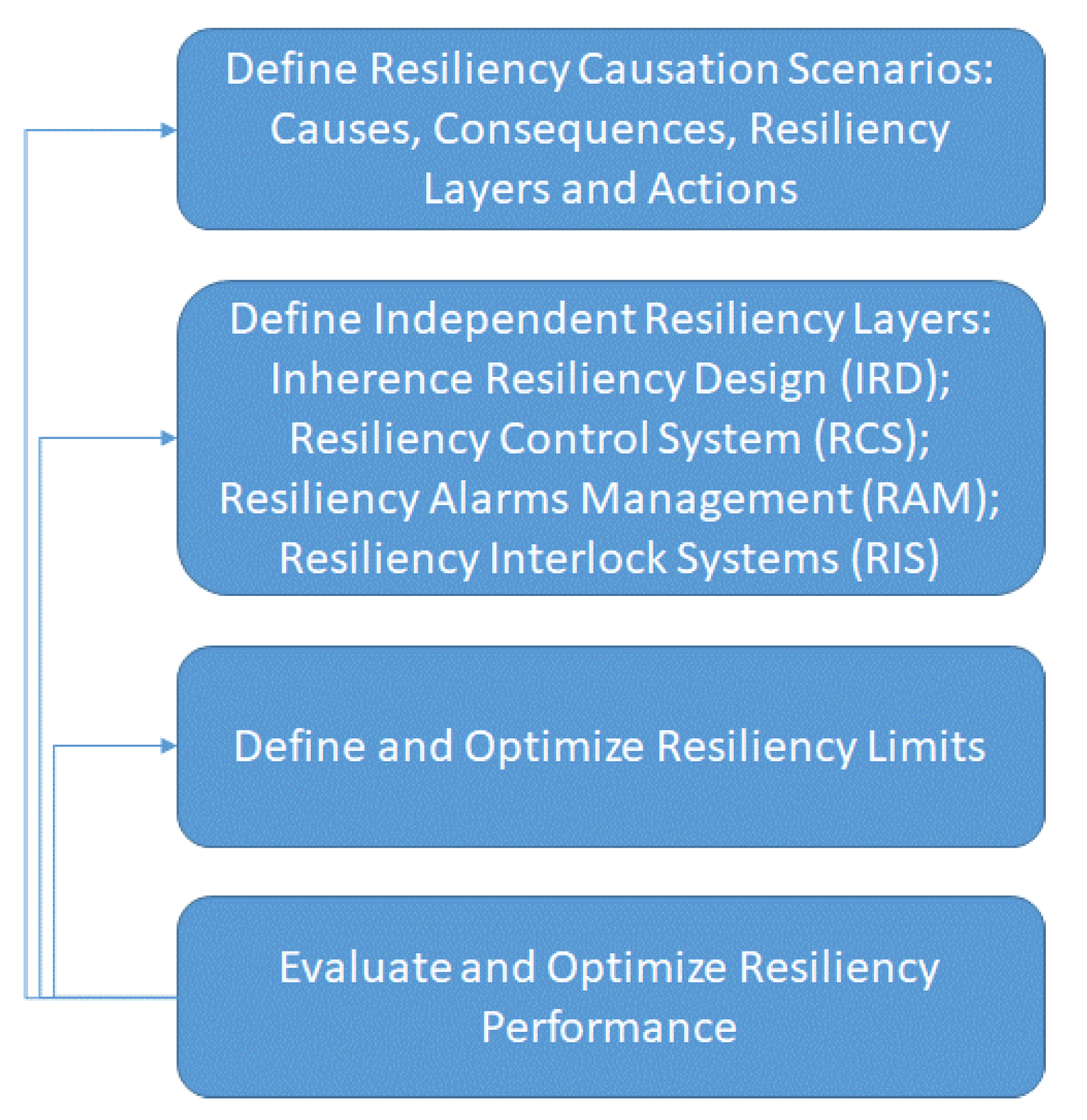
In order to implement resiliency layers for HES within interconnected infrastructures, an integrated framework for resiliency design is proposed as shown in Figure 7.
The proposed resiliency design starts with the analysis of resiliency causation scenarios, with causes, consequences, and resiliency actions. Independent resiliency layers are defined based on inherent resiliency layers (IRD), resiliency control system (RCS), resiliency alarm management (RAM), and resiliency interlock systems (RIS).
The resiliency propagation and control model is presented with possible links between resiliency top event and escalation factors as well as resiliency barrier controls are shown in Figure 8. From causes of any disturbance to the HES within interconnected infrastructures, there are number of possible resiliency barriers. Each resiliency barrier could be controlled by energy load via demand side management, or energy supply with cogeneration, and also energy storage by diversity of energy storage from battery and flywheel as well as thermal and gas storage. Each barrier could be evaluated with respect to response time and performance gap, while ensuring controls are implemented in the design and control.
Resiliency limits are defined and optimized as part of energy load, supply, storage, and conversion for electricity, thermal, gas, including interconnected systems from water-waste-transportation-food-health-social infrastructures. Resiliency limits are dependent as explained in Table 1.
Each component of the resiliency layers will be evaluated to ensure target response will meet the target performance.
5. Resiliency Analysis
This section presents resiliency analysis framework which includes resiliency causation analysis, independent resiliency layers, and integrated resiliency and protection analysis. Moreover, resiliency estimation is presented with simplified examples.
5.1. Resiliency Causation Scenarios
The following table represents a detailed analysis of resiliency causation scenarios where causes and consequences are analyzed and associated with possible resiliency layers. Resiliency events are defined as the initiating events that will require resiliency layers. These examples are described in Table 2 below.
5.2. Resiliency Performance Estimation
The cost and efforts needed to design resiliency layers are justified based on losses caused to lack of resiliency. The estimation of the losses due to lack of resiliency will be used to optimize resiliency layers. Resiliency losses are represented with time taken to return back to normal (or close to normal) condition after disturbances. In order to understand the proposed resiliency estimation method, a simple example of set of disturbances are introduced to a given system. The start time of introducing the disturbance is recorded as “Start Time”. The time system returned back after resiliency layer is activated is “Return Time”. The ideal performance is defined as “P-Ideal”, while the performance of the system after returning back close or reaching normal performance is defined as “P-Reached”. Response time is the time difference between start and return time. Performance gap is the difference between original system performance and the achieved performance after applying resiliency layers, which is defined as “P-Gap”. One definition of resiliency performance is defined as “R” which is the reciprocal of response time multiplied by performance difference. This is useful where the more response time the lower the resiliency performance of the system. Similarly, the larger the difference in performance the lower the resiliency performance. Another definition of the resiliency performance “R” is based on weighted multiplication of each resiliency factor, i.e., response time and performance gap. Table 3 shows the detailed calculations of the simplified example of different disturbances applied on a given system, where both resiliency performance measures are estimated.
The propagation from initiating events till reaching the limits of resiliency activation could have preventative measures in the form of resiliency layers, as discussed above. The probability of success or failure of these resiliency layers will be estimated based reliability of components and functions of these layers. The overall resiliency of the system will be quantified based on multiple resiliency layers. In case the resiliency layer is not able to return system back to normal, it might be possible to reach safety margins where protection layers will be activated.
5.3. Resiliency Performance Coupling
For the given HES within interconnected infrastructures as per the example above, resiliency performance coupling could be evaluated in view of interfaces and associated process variables from different domains, while analyzing the coupling among these variables to reflect to resiliency performance.
where,
- : total KPI for the whole interconnected systems;
- ;
- ;
- ;
- ;
- ;
- ;
- ;
- ;
- ;
- ;
- ;
- .
The detailed calculation of each performance measure and associated weights are based on system modeling and will be reflected into resiliency coupling among these systems. Examples of weights could be estimated as a normalized number between zero and one, where higher value will be used for more important KPI on the overall performance. Furthermore, the use of sensitivity analysis could be applied to measure the impact of the weight factor by applying small changes in the input parameters to see impacts on the overall performance based on different weight factor. This will open the door for additional analysis and system modeling and tool development for integrated resiliency and protection system for hybrid energy systems and interconnected infrastructures.
6. Conclusions
Smart cities are achieved by enabling interconnected and smart infrastructures where real time interactions among energy-water-transportation-waste-food-health-social systems could offer enhanced overall performance with energy savings, and reduced operating costs. In order to assure the resiliency of the overall system an integrated resiliency analysis framework is proposed where four main resiliency layers are proposed. Resiliency analysis of hybrid energy systems within interconnected infrastructures is illustrated using resiliency causation scenarios where causes, consequences, and mapped to resiliency actions. A simplified resiliency performance model is proposed to compare resiliency performance in view of design and operation scenarios. Resiliency performance is evaluated in view of two parameters: (a) response time where system return back to ideal performance after activating resiliency layers; (b) performance gap between the ideal performance and the performance where system returned back after activating resiliency layers. The proposed model will allow optimizing resiliency performance in view design and operation scenarios and control strategies of hybrid energy systems within interconnected infrastructures.
The proposed resiliency analysis framework is practical and novel where no prior studies are made in the past to facilitate the systematic design and validation of resiliency layers. The proposed resiliency analysis framework is demonstrated and applied on a case study hybrid energy systems within interconnected infrastructures. The research will be extended to include modeling and simulation with optimization based on the proposed resiliency design framework.
Funding
This research is supported by Natural Sciences and Engineering Research Council of Canada (NSERC)—Discovery Grant 210320.
Institutional Review Board Statement
Not applicable.
Informed Consent Statement
Not applicable.
Data Availability Statement
Not applicable.
Acknowledgments
This research is supported by Natural Sciences and Engineering Research Council of Canada (NSERC)—Discovery Grant 210320. The author thanks all Smart Energy Systems Lab (SESL) members at Ontario Tech University for their support.
Conflicts of Interest
There is no conflict of interests.
References
- Gabbar, H. Modeling of Interconnected Infrastructures with Unified Interface Design Toward Smart Cities. Energies 2021, 14, 4572. [Google Scholar] [CrossRef]
- Craig, G.; Eilín, W.; Kevin, M.; Philip, O. Regional Integration of Renewable Energy Systems in Ireland The Role Of Hybrid Energy Systems for Small Communities. Int. J. Electr. Power Energy Syst. 2013, 44, 713–720. [Google Scholar]
- Marcus, L.; Anne Marie, O.; Robert, D.; Martin, L.T.; Valerie, C.V. Governance Barriers to Sustainable Energy Transitions—Assessing Ireland’s Capacity towards Marine Energy Futures. Energy Policy 2018, 113, 623–632. [Google Scholar]
- Diab, F.; Lan, H.; Ali, S. Novel Comparison Study between The Hybrid Renewable Energy Systems on Land and on Ship. Renew. Sustain. Energy Rev. 2016, 63, 452–463. [Google Scholar] [CrossRef]
- Ustun, T.S.; Ozansoy, C.; Zayegh, A. Modeling of a Centralized Microgrid Protection System and Distributed Energy Resources according to IEC 61850-7-420. IEEE Trans. Power Syst. 2012, 27, 1560–1567. [Google Scholar] [CrossRef]
- Arash, B.; Kieran, P.D.; Richard Geddes, R.; Oliver Gao, H. Climate-Adaptive Planning for The Long-Term Resilience of Transportation Energy Infrastructure. Transp. Res. Part E Logist. Transp. Rev. 2018, 113, 99–122. [Google Scholar]
- Heng, C.X.; Ju, H.P.; Peng, S. Fuzzy Resilient Energy-To-Peak Filtering for Continuous-Time Nonlinear Systems. IEEE Trans. Fuzzy Syst. 2017, 25, 1576–1588. [Google Scholar]
- Nik, V.M.; Perera, A.T.D.; Chen, D. Towards Climate Resilient Urban Energy Systems: A Review. Natl. Sci. Rev. 2021, 8, 134. [Google Scholar] [CrossRef] [PubMed]
- Hamilton, M.C.; Lambert, J.H.; Connelly, E.B.; Barker, K. Resilience Analytics with Disruption of Prefer-Ences And Lifecycle Cost Analysis for Energy Microgrids. Reliab. Eng. Syst. Saf. 2016, 150, 11–21. [Google Scholar] [CrossRef]
- Fathima, A.H.; Palanisamy, K. Optimization in Microgrids With Hybrid Energy Systems—Review. Renew. Sustain. Energy Rev. 2015, 45, 431–446. [Google Scholar] [CrossRef]
- Arghandeh, R.; Uzunoglu, B.; D’arco, S.; Ozguven, E.E. Data Driven Reliable and Resilient Energy System against Disasters. IEEE Trans. Ind. Inform. 2021, 1. [Google Scholar] [CrossRef]
- Chao, D.; Yu, W.; Changyun, W.; Yan, X.; Pengfeng, L. Distributed Resilient Control for Energy Storage Systems in Cyber-Physical Microgrids. IEEE Trans. Ind. Inform. 2021, 17, 1331–1341. [Google Scholar]
- Kexing, L.; Illindala, M.S. A Distributed Energy Management Strategy for Resilient Shipboard Power System. Appl. Energy 2018, 228, 821–832. [Google Scholar]
- Georgescu-Roegen, N. The Entropy Law and the Economic Process; Harvard University Press Partnered With De Gruyter: Cambridge, MA, USA, 1971; ISBN 9780674281653. [Google Scholar]
Figure 1.
HES within interconnected infrastructures.

Figure 2.
Modeling of energy-water Interconnections.

Figure 3.
Example of HES within interconnected infrastructures.

Figure 4.
Interfaces with water pumps within interconnected infrastructures.

Figure 6.
Integrated resiliency and protection layers.

Figure 7.
Proposed resiliency design framework.

Figure 8.
Resiliency propagation and control analysis.


Table 1.
Resiliency limits dependencies.
| Resiliency Limits of Energy Load | Electricity, Thermal, Gas/Hydrogen |
|---|---|
| Resiliency Limits of Energy Supply | Electricity, Thermal, Gas/Hydrogen |
| Resiliency Limits of Energy Storage | Electricity, Thermal, Gas/Hydrogen |
| Resiliency Limits of Water Load | Energy-Water Interconnected Systems |
| Resiliency Limits of Water Supply | Energy-Water Interconnected Systems |
| Resiliency Limits of Water Storage | Energy-Water Interconnected Systems |
Table 2.
Resiliency causation scenarios.
| Causes | Consequences | Possible Resiliency Layers |
|---|---|---|
| 1. Demand related scenarios | ||
| 1.1. Increase in energy demand | Energy not served | Demand side management |
| Deterioration of energy systems | Increase energy storage | |
| Increased energy price from grid | Increase cogeneration | |
| Scheduled/interrupted energy supply | Increase energy conversion | |
| Activate protection layers | ||
| 1.2. Decrease in energy demand | Higher load on grid | Activate protection layers |
| Deterioration of energy systems | Increase energy storage | |
| Increase maintenance | ||
| 1.3. Fluctuation of energy demand | Same as increase/decrease in energy demand | |
| 2. Supply related scenarios | ||
| 2.1. Increase in energy supply | Higher load on grid | Activate protection layers |
| Deterioration of energy systems | Increase energy storage | |
| Increase maintenance | ||
| 2.2. Decrease in energy supply | Energy not served | Demand side management |
| Deterioration of energy systems | Increase energy storage | |
| Increased energy price from grid | Increase cogeneration | |
| Scheduled/interrupted energy supply | Increase energy conversion | |
| Activate protection layers | ||
| 2.3. Fluctuation in energy supply | Same as increase/decrease in energy supply | |
| 2.4. Increase in energy supply price | With limited budget, less cover to demand | Increase energy storage |
| 2.5. Decrease in energy supply price | Reduced profits of energy system owners | Increase energy storage |
| 2.6. Fluctuation in energy supply price | Same as increase/decrease in energy supply price | |
| 3. External Factors | ||
| 3.1. Earthquake/flood/storm | Damage to energy supply | Same as 2.2. |
| Damage to energy storage | Demand side management to close gap between supply and demand | |
| Increase energy supply | ||
| Increase energy storage | ||
| Damage to energy loads | Fix issues with damaged loads | |
| Same as 2.1. | ||
| 3.2. Special events | Increase in energy demand | Same as 1.1. |
| 3.3. Terror/Hacking | Damage to energy supply | Same as 2.2. |
| Damage to energy storage | Demand side management to close gap between supply and demand | |
| Increase energy supply | ||
| Increase energy storage | ||
| Damage to energy loads | Fix issues with damaged loads | |
| Same as 2.1. | ||
| 4. Impacts from Interconnected Systems | ||
| 4.1. Increase in water demand | Increase in energy demand (needed for water pumps and networks) | Same as 1.1. |
| 4.2. Decrease in water demand | Decrease in energy demand | Same as 1.2. |
| 4.3. Increase in transportation demand | Increase in energy demand (needed for increased EV) | Same as 1.1. |
| 4.4. Decrease in transportation demand | Decrease in energy demand | Same as 1.2. |
| 4.5. Increase in waste | Increase in energy supply (as output from waste-to-energy) | Same as 2.1. |
| 4.6. Decrease in waste | Decrease in energy supply | Same as 2.2. |
| 4.7. Increase in food demand | Increase in energy demand for processing food production/supply | Same as 1.1. |
| 4.8. Decrease in food demand | Decrease in energy demand | Same as 1.2. |
| 4.9. Increase in health demand | Increase in energy demand (to support health systems) | Same aas 1.1. |
| 4.10. Decrease in health demand | Decrease in energy demand | Same as 1.2. |
| 4.11. Increase in social demand | Possible increase in energy demand (to support mobility) | Same as 1.1. |
| 4.12. Decrease in social demand | Possible decrease in energy demand | Same as 1.2. |
| 4.13. Decrease in human performance | Possible deterioration of energy systems (with reduced operation and maintenance) | Activate protection layers |
| Increase maintenance | ||
| Increase energy storage | ||
| Increase energy supply | ||
| 4.14. Decrease in system performance | Possible deterioration of energy systems | Activate protection layers |
| Increase maintenance | ||
| Increase energy storage | ||
| Increase energy supply | ||
| 4.15. Change in geopolitical | Possible reduction of energy supply | Same as 2.2. |
Table 3.
Illustrative example of resiliency estimation.
| Disturbance | Start Time | Return Time | P-Reached | P-Ideal | Response | P-Gap | Resilience | Resilience-1 | Resilience-2 | Net Resilience |
|---|---|---|---|---|---|---|---|---|---|---|
| number | t1 | t2 | d1 | d2 | t2 − t1 | |d1 − d2| | R′ | R1 | R2 | R |
| 1 | 2 | 5 | 82 | 90 | 3 | 8 | 4.17 | 91.11 | 40 | 50.22 |
| 2 | 2 | 4 | 82 | 90 | 2 | 8 | 6.25 | 91.11 | 50 | 58.22 |
| 3 | 2 | 5 | 80 | 90 | 3 | 10 | 3.33 | 88.89 | 40 | 49.78 |
| 4 | 2 | 4 | 80 | 90 | 2 | 10 | 5.00 | 88.89 | 50 | 57.78 |
: weight for ; : weight for ; : resiliency factor related to performance gap; : resiliency factor related to response time; : resiliency calculation based on reciprocal of response time difference and performance gap; R: resiliency calculation based on weighted summation of resiliency factors.
Publisher’s Note: MDPI stays neutral with regard to jurisdictional claims in published maps and institutional affiliations. |
© 2021 by the author. Licensee MDPI, Basel, Switzerland. This article is an open access article distributed under the terms and conditions of the Creative Commons Attribution (CC BY) license (https://creativecommons.org/licenses/by/4.0/).
Share and Cite
MDPI and ACS Style
Gabbar, H.A. Resiliency Analysis of Hybrid Energy Systems within Interconnected Infrastructures. Energies 2021, 14, 7499. https://doi.org/10.3390/en14227499
AMA Style
Gabbar HA. Resiliency Analysis of Hybrid Energy Systems within Interconnected Infrastructures. Energies. 2021; 14(22):7499. https://doi.org/10.3390/en14227499
Chicago/Turabian StyleGabbar, Hossam A. 2021. "Resiliency Analysis of Hybrid Energy Systems within Interconnected Infrastructures" Energies 14, no. 22: 7499. https://doi.org/10.3390/en14227499
Note that from the first issue of 2016, this journal uses article numbers instead of page numbers. See further details here.