Review

A Comprehensive Overview of Hydrogen-Fueled Internal Combustion Engines: Achievements and Future Challenges

by
Zbigniew Stępień
Oil and Gas Institute—National Research Institute, 31-503 Kraków, Poland
Energies 2021, 14(20), 6504; https://doi.org/10.3390/en14206504
Submission received: 13 August 2021 / Revised: 27 September 2021 / Accepted: 28 September 2021 / Published: 11 October 2021
(This article belongs to the Special Issue Hydrogen-Fuelled Spark-Ignition Engines)

Abstract

:
This paper provides a comprehensive review and critical analysis of the latest research results in addition to an overview of the future challenges and opportunities regarding the use of hydrogen to power internal combustion engines (ICEs). The experiences and opinions of various international research centers on the technical possibilities of using hydrogen as a fuel in ICE are summarized. The advantages and disadvantages of the use of hydrogen as a solution are described. Attention is drawn to the specific physical, chemical, and operational properties of hydrogen for ICEs. A critical review of hydrogen combustion concepts is provided, drawing on previous research results and experiences described in a number of research papers. Much space is devoted to discussing the challenges and opportunities associated with port and direct hydrogen injection technology. A comparison of different fuel injection and ignition strategies and the benefits of using the synergies of selected solutions are presented. Pointing to the previous experiences of various research centers, the hazards related to incorrect hydrogen combustion, such as early pre-ignition, late pre-ignition, knocking combustion, and backfire, are described. Attention is focused on the fundamental importance of air ratio optimization from the point of view of combustion quality, NOx emissions, engine efficiency, and performance. Exhaust gas scrubbing to meet future emission regulations for hydrogen powered internal combustion engines is another issue that is considered. The article also discusses the modifications required to adapt existing engines to run on hydrogen. Referring to still-unsolved problems, the reliability challenges faced by fuel injection systems, in particular, are presented. An analysis of more than 150 articles shows that hydrogen is a suitable alternative fuel for spark-ignition engines. It will significantly improve their performance and greatly reduce emissions to a fraction of their current level. However, its use also has some drawbacks, the most significant of which are its high NOx emissions and low power output, and problems in terms of the durability and reliability of hydrogen-fueled engines.

1. Introduction

Under the proposed Green Deal program, the European Union will aim to achieve zero net greenhouse gas emissions by 2050. The interim target is to reduce GHG by 55% (relative to the 1990 reference year) by 2030. Only a 20% reduction has been achieved by 2020, so significant additional efforts are required to meet the target. The requirement for CO2-neutral powertrains to have the lowest possible emissions compared with other regulated exhaust components is a key factor in the diversification of future fuels. Today, an alternative fuel must not only be technically feasible and economically viable to produce but, above all, must reduce environmentally harmful emissions, including CO2, to the greatest possible extent. Current alternative fuels such as ethanol, methanol, biodiesel, propane, natural gas, and hydrogen can reduce engine emissions to varying degrees compared to emissions caused by conventional liquid hydrocarbon fuels. Of these, hydrogen, as an energy carrier, is the only fuel that is potentially free of hydrocarbon, carbon monoxide, and carbon dioxide emissions. Hydrogen has a very high combustion velocity in the engine combustion chamber (about 6 times higher than petrol), which contributes to high engine efficiency [1,2,3,4]. Hydrogen also has a wide range of flammability, which allows it to burn in engines when mixed with air in a wide range of different proportions (4–75%). This enables the use of very lean mixtures. Based on the research conducted so far, over 5% higher efficiency of a hydrogen-fueled reciprocating internal combustion engine compared to a diesel-fueled ZS engine (about 44.5% for a prototype engine) has already been achieved [1,2,3,4,5,6]. Therefore, hydrogen is considered one of the most important fuels of the future. Its use will make it possible to meet increasingly stringent emissions standards. Consequently, hydrogen is one of the most important candidates for satisfying future energy demands (including its application as a fuel for future vehicle powertrains) and plays a key role in most government strategic plans [4,5,6,7,8,9,10,11]. Hydrogen, as a sustainable fuel of the future, will reduce global dependence on fossil fuel resources and the level of exhaust emitted from motor vehicles [1,2,3,4,5,6, 9,10,11,12,13,14,15,16]. However, the quantities of emissions are highly influenced by the method of hydrogen production [17,18,19,20,21,22,23,24].
Various methods are currently used to produce hydrogen [2,3,4]. Currently, the most widely used method to produce hydrogen is steam methane reforming. In this case, the efficiency of hydrogen production is very high (65–75%) and the costs are relatively low. However, in this case, hydrogen production results in high levels of CO2 emission [3,4,5,11,25,26,27,28,29,30,31]. Another widely used method of hydrogen production is coal gasification. In this case, however, the efficiency of hydrogen production is low (45%) and CO2 emissions are high. Electrolysis of water is another method of producing hydrogen, but it requires the use of large amounts of electricity and is therefore very expensive. In this case, the level of CO2 emissions depends on the electricity source. Less common methods can also be used to produce hydrogen, such as biomass gasification, biomass-derived liquid reforming, or microbial biomass conversion [3,4,5,11,25,26,27,28,29,30,31]. However, only the solar–hydrogen system allows emission-free—but expensive—hydrogen production. In 2016, 96% of total hydrogen was produced from fossil fuels [6]. However, when fossil hydrocarbons are used, CO2 is produced during reforming. In order to prevent its emission into the atmosphere, it must be captured and stored [2,3,5,11,28,29,30,31,32,33,34,35,36,37,38,39]. The use of hydrogen as a fuel for internal combustion engines (ICEs) or fuel cell (FC) vehicles is a promising trend for the transport sector in future. An internal combustion engine may be operated using different fuels. However, it requires appropriate adjustment of the engine control unit and the material compatibility of engine components with different fuels [9,10,11,12,13]. The use of hydrogen as a fuel to power ICEs has significant advantages over FC technology. The most important of these are greater tolerance to contamination, maturity of the ICE technology, reduced consumption of scarce materials, and easy adaptation of the ICE to run on hydrogen [7,8,9,10,11,12]. Hydrogen-fueled ICEs (H2ICEs) have been the subject of research since the last century [13,14,15,16,17,18,19,20,21,22,23,24,25,33,34,35,36,37]. Figure 1 provides a critical comparison of the torque and power output characteristics of an internal combustion engine versus an electric motor as a power source in BEVs and FCEVs [26,36,37,38,39,40].
Noteworthy is the torque of the electric motor, which is very high at low motor speeds but decreases hyperbolically with increasing motor speed. The power output of an electric motor is represented by a flat line because each electric motor has a constant power rating to avoid overheating and to prevent damage to the electrical wiring insulation. By contrast, the torque of an internal combustion engine remains more or less constant with increasing engine speed (particularly the case for supercharged engines). Consequently, the ICE has greater power output at higher engine speeds. As can be seen in Figure 1, above a certain speed, there is an excess of ICE output power. This is favorable and typical characteristic of internal combustion engines, including those fueled with hydrogen [26].
According to standards set by the EU, a vehicle qualifies as zero-emission if it meets the following criteria:
For a heavy-duty vehicle without or with an internal combustion engine, its emissions must be less than 1 g CO2/kWh, as defined in accordance with Regulation (EC) No 595/2009 and its implementing measures, or which emits less than 1 g CO2/km as determined in accordance with Regulation (EC) No 715/2007 of the European Parliament and of the Council and its implementing measures (European Parliament, 2019).
Currently, the hydrogen-powered internal combustion engine is the only known internal combustion engine that meets these strict EU regulations. A hydrogen-powered engine also emits significantly lower levels of other pollutant species compared to a diesel-powered engine. The only significant pollutants that are potential byproducts of H2 combustion are nitrogen oxides (NOx). However, using an advanced combustion process and a relatively simple aftertreatment system, NOx emissions can be reduced to near zero. An important advantage of a hydrogen-powered ICE is that the technology can be brought to the market quickly and therefore be practically disseminated with minimal delay should the use of diesel vehicles be gradually reduced in the coming years [27,28,29,35,36,41,42,43]. Several types of low-emission propulsion systems are currently being considered for use in the near and distant future, considering the need for diversification in conjunction with specific applications. These propulsion systems include the increasingly widespread use of electric drives powered with batteries (BEVs) or fuel cells (FCEVs), internal combustion engines powered with synthetic fuels, and internal combustion engines powered with hydrogen and hybrid powertrains. Each of these drives has its own advantages and disadvantages that enable their optimal use only in a specific application. Table 1 compares the two powertrains currently most commonly considered as the future of road transport, i.e., battery electric and fuel cell electric powertrains as well powertrain based on the traditional hydrogen-powered internal combustion engine.
As can be seen in Table 1, battery electric vehicles (BEVs) have considerable potential, especially in urban traffic, where they are sufficient for short ranges. Fuel cell electric vehicles (FCEVs) can perform well in large and heavy vehicles and trucks where an extended range is required. However, the fuel cell has high thermal management requirements, is less robust and durable, and requires a hydrogen purity level of >99.9% as opposed to hydrogen-fueled vehicle engines that have the fewest weaknesses and are the most versatile [28]. Thus, H2-ICE powertrains are a viable alternative to battery-electric mobility and fuel cells, especially for light- and heavy-duty vehicles in the medium-to-long terms with regard to both the CO2 equivalent and performance characteristics. Today, the prospects for hydrogen mobility are better than ever, and hydrogen internal combustion engines (H2-ICEs) are one of the pillars of this mobility solution [30,33,42,43].

2. Thermophysical Properties of Hydrogen as a Fuel for Internal Combustion Engines

The physical and chemical properties of hydrogen differ significantly from those of conventional fossil fuels [11,15,16,31,32,33,34,35,44,45,46,47,48]. Several key properties of hydrogen have had a major impact on the design changes and technological developments of internal combustion engines. The main characteristics of a hydrogen fuel compared to other fuels commonly used in ICEs are presented in Table 2 [11,15,33,34,44,45,46,47,48,49,50,51].
At atmospheric pressure and a temperature of 273 K, the density of hydrogen is very low, less than that of natural gas by an order of magnitude. This is due to its very low molecular weight. Hydrogen has the highest mass–energy ratio among the chemical fuels and, in terms of mass–energy consumption, it outperforms conventional gasoline fuel by approximately 3 times, alcohol by 5 to 6 times, and methane and propane by 2.5 times. Therefore, an admixture of hydrogen to hydrocarbon fuel can be used to increase effective engine efficiency and reduce specific fuel consumption. The low density of hydrogen results in reduced energy density of the hydrogen-air mixture inside the engine cylinder, leading to a low power output. An effective method to eliminate the reduction in power output is to use direct H2 injection with the intake valve closed. To increase the hydrogen density and the associated volumetric energy content, it is necessary to increase the hydrogen storage pressure. As an example, hydrogen compressed to 350 bar at 273 K can increase the density of the gas to 31 kg/m3. At the same time, the volumetric energy content increases to 3700 MJ/m3 [30,34,35,36,42,43,46]. Beneficial for the combustion process are the high molecular diffusivity and flame speed of the burning hydrogen resulting in a faster production of a homogeneous mixture of fuel and air, and a better combustion efficiency and cycle-to-cycle variation in a wide range inside the cylinder. The use of gaseous fuel for short periods during engine start-up and warm-up eliminates problems associated with the evaporation of cold liquid fuel. It also reduces the uneven distribution of fuel to the cylinders due to the presence of a layer of liquid on the intake manifold walls. This, in turn, prevents undesirable changes in the fuel–air mixture ratio in the various cylinders of the engine during transients such as acceleration or deceleration. Hydrogen has wide flammability limits compared to other fuels (4–75% compared to 1.4–2.3% by volume in air in the case of gasoline). A significant advantage of this is that hydrogen can run on a lean mixture. It is characterized by a wide range of flammability limits, with flammable mixtures ranging from as poor as λ = 10 to as rich as λ = 0:14 (0:1 < ϕ (fuel/air equivalence ratio) < 7:1). This makes it possible to achieve a wide range of engine power by varying the mixture composition. Additionally, hydrogen wide flammability limits, allowing unthrottled engine operation at partial loads with a subsequent improvement in thermal efficiency [9,10,15,16,21,51,52,53]. The flammability limits widen with the increasing temperature with the lower flammability limit dropping to 2 vol % at 300 °C (equivalent to λ = 20/ϕ = 0:05) [16,36]. The lower flammability limit increases with increasing pressure, with the upper flammability limit taking different values in the pressure-dependent range. That, however, is less relevant regarding its application in engines [37]. Running the engine on a lean mixture produces a low flame temperature. This leads to less heat transfer to the walls and allows increased fuel economy due to the total fuel burnt. In addition, the wide flammability range of hydrogen enables ultra-efficient engine operation, resulting in lower NOx emissions and increased brake thermal efficiency [33,38,39,51,52]. There is a limit to the leanness of a fuel mixture. Running the engine with a lean mixture can significantly reduce the power output. The reason for this is a reduction in the volumetric heating value of the fuel–air mixture. The minimum energy required to ignite a hydrogen–air mixture under atmospheric conditions is very low, an order of magnitude lower than that for the methane–air and iso-octane–air mixtures. It is only 0.017 mJ (compared to 0.24 mJ for a gasoline-air mixture) for hydrogen concentrations of 22–26% (λ = 1:2–1:5/ϕ = 0:67–0:83) [16,39,40,41,42]. The figure quoted above corresponds to a spark plug gap of 0.5 mm. For a spark plug gap of 2 mm, the minimum ignition energy is approximately 0.05 mJ. This is approximately constant for hydrogen concentrations between 10% and 50% (λ = 0.42–3.77, ϕ = 0.27–2.38). When the hydrogen concentration drops below 10%, its sharp increase occurs. This poses a risk of the hot gases and hot spots in the combustion chamber becoming a source of premature ignition and flashback. Due to the very low ignition energy, a low-energy spark is sufficient to initiate combustion. Therefore, the combustion process can be initiated by a glow plug or a resistance hot wire [33,42,43,44,49,50,51,52,53,54,55,56,57]. Hydrogen has a small quenching distance of merely 0.6 mm, which is much shorter than that of gasoline. The quenching distance is the distance from the inner wall of the cylinder below which the combustion flame extinguishes. For nearly stoichiometric mixtures, it is minimal and decreases with increasing pressure and temperature. Consequently, hydrogen flames are closer to the cylinder wall before they are extinguished compared to other fuels. This has a considerable impact on the crevice combustion and heat transfer through the walls [16,35,42,43,44,45,46]. It is more difficult to extinguish a hydrogen flame compared with other fuels. It tends to backfire, especially since it may escape through a nearly closed intake valve [33,42,43,44,45,46,47]. The hydrogen flame ignites and burns quickly and is therefore relatively short-lived [39,45,46,47,48,49]. Unfortunately, the low flame quenching distance of hydrogen also results in increased lubricant evaporation, and as a result to increased particle formation in DI hydrogen ICEs [36,42,43,44,45,46,47,48,49].
The autoignition temperature of hydrogen is 853 K, significantly higher than that of other fuels. This makes ignition of the hydrogen–air mixture much more difficult when relying only on temperature increase during compression. Thus, ignition of a hydrogen–air mixture is difficult without an additional ignition source, and this is important when a mixture of hydrogen and air is compressed. The autoignition temperature is important because it allows the maximum compression ratio of the engine to be determined due to the relationship of temperature rise during compression to the compression ratio. Furthermore, this temperature allows higher compression ratios to be used in hydrogen-fueled engines [40,41,42,43]. Due to its very high autoignition temperature and octane number, resistance to knocking combustion should be higher for hydrogen than for hydrocarbon fuels [47]. Of note, the unambiguous, precise upper limit of the hydrogen octane number has not been established [30,46]. Its minimum ignition energy in air at stoichiometric ratios is an order of magnitude lower than that of hydrocarbon fuels. This poses the risk of hydrogen ignition from hot spots or residues in the combustion chamber. Consequently, this can result in the premature initiation of uncontrolled fuel ignition. There are, therefore, risks regarding loss of control of the combustion process, knocking combustion, and the possibility of mechanical damage to the engine [30,47]. The motor octane number (MON) of hydrogen is significantly lower than its RON compared to a typical drop of 8–10 points for gasoline. The exact MON of hydrogen, however, has not been clearly defined. However, there is a view that the MON is a more accurate measure of resistance to knock combustion in hydrogen engines [47,54,55,56,57,58].
For the complete combustion of hydrogen in air, the stoichiometric or chemically correct A/F ratio (λ) is 34.29 kg air to 1 kg hydrogen. This corresponds to a stoichiometric percentage of 29.52% hydrogen in air by volume. This is much higher than the 14.7:1 (A/F) ratio required for gasoline. Hydrogen has a high flame speed at stoichiometric ratios, and under these conditions, the hydrogen flame speed is nearly an order of magnitude higher (faster) than that of gasoline. This allows hydrogen engines to more closely approximate the thermodynamically ideal engine cycle. At leaner mixtures, the flame velocity decreases significantly, and the fuel economy improves. The adiabatic temperature of the flame and its velocity affect engine parameters such as thermal efficiency, combustion stability, exhaust emissions, etc. Another property of hydrogen is its very high diffusivity. The ability of hydrogen to disperse in air is much greater than that of petrol. This is advantageous for two main reasons: it facilitates the formation of a homogeneous mixture of fuel and air; and from the point of view of application safety, it disperses rapidly in the event of a hydrogen leak [33,41,47,48,53,55,58].

3. Hydrogen Use in Internal Combustion Engines

Hydrogen can be used in spark ignition (SI) as well as compression ignition (CI) engines.

3.1. Spark Ignition Engines

Hydrogen has considerable potential in applications to power spark ignition engines and to achieve good performance. Some beneficial properties of hydrogen, such as fast flame propagation, low ignition energy, and a wide operating range, allow for optimization and improvement of the combustion process. This makes it possible, among other things, to limit the emission of harmful components to only NOx [15,30,33,41,49,50,51,52,53]. Hydrogen in SI engines can be used in one of the following ways [52,53,54,55,56,57,58,59]:
-
Manifold induction—Low-temperature hydrogen is injected into the manifold through a valve controlled duct.
-
Direct introduction—A cryogenic cylinder is used to store hydrogen. A pump circulates liquid hydrogen to a heat exchanger to vaporize it. Then, cold hydrogen is injected into the engine. By using cold hydrogen, pre-ignition is avoided and NOx formation in the combustion process is reduced.
-
Hydrogen addition to gasoline: In this method, a mixture of hydrogen and petrol is introduced into the combustion chamber of an internal combustion engine. There, the compressed mixture is ignited by a spark.
Hydrogen fuel, when mixed with air, forms a combustible mixture. It can be burned in a conventional spark ignition engine with an equivalence ratio below the flammability limit of a gasoline–air mixture. The resulting ultra-lean combustion produces low flame temperatures. This directly leads to lower heat transfer to the walls, higher engine efficiency, and lower NOx emissions. This is an important advantage of hydrogen-powered SI engines. Hydrogen-powered engines have lower unwanted emissions compared to hydrocarbon-fueled engines. Previous studies have shown that the main pollutants in hydrogen engines are NOx as well as PM. NOx emissions from hydrogen-fueled ICEs are higher than from petrol-fueled ICEs due to the high combustion temperature. Due to the higher combustion temperatures, high NOx emissions occur especially when the engine is operating in the stoichiometric fuel-to-air ratio range. Reducing the air–fuel ratio decreases the combustion temperature and NOx emissions.
Spark ignition engines can be fueled with hydrogen without requiring major modifications. A higher hydrogen burning velocity improves combustion and allows for higher brake thermal efficiency. Emissions of hydrocarbons and carbon monoxide are virtually negligible. Only trace amounts of these emissions are produced by the evaporation and burning of the lubricating oil film on engine cylinder walls [39,55,56,57,58,59]. The performance of a hydrogen engine is better than that of a gasoline-powered engine, particularly under part-load operation. Hydrogen can also be used as an admixture in methane or petrol. This makes it possible to burn very lean mixtures with an equivalence factor of 0.1. However, spark ignition engines are an inferior solution where high levels of torque are required at low engine speeds. In such cases, engines operating at higher compression ratios, such as diesels, are usually used.

3.2. Compression Ignition Engines

There are several reasons for using hydrogen as a diesel fuel additive in compression ignition (CI) internal combustion engines [60,61,62,63]. The injection of small amounts of hydrogen into a CI internal combustion engine improves the homogeneity of mixing in the diesel spray stream. This is largely due to the high diffusivity of hydrogen. As a result, the combustible mixture is more thoroughly mixed with air [34,60,61,62,63,64,65,66]. As such, the formation of hydrocarbons, carbon monoxide, and carbon dioxide during combustion can be almost completely eliminated. Only the partial combustion of lubricating oil can produce trace amounts of these compounds in the combustion chamber [61,62,63]. In hydrogen-fueled CI engines, an injector is used to inject high-pressure hydrogen into the cylinder. Therefore, not only is the design of the engine structure important but that of the injector because the injection nozzle controls how pressurized hydrogen is injected into the combustion chamber [62,63,64,65]. Compression ignition engines cannot be operated with hydrogen as a standalone fuel the compression temperature is insufficient for initiating combustion due to the higher autoignition temperature required [61,62,63,64,65]. Therefore, burning hydrogen in a CI engine requires the aid of a spark plug or a glow plug. With a dual-fuel engine, the main fuel (hydrogen) is injected into the intake air or carburetor. Combustion is initiated by the diesel fuel acting as an ignition source. The amount of pilot fuel can be 10–30% of the total fuel, with the rest of the energy provided by the main fuel (hydrogen). Similarly to SI engines, nitrogen oxides (NOx) are a major problem in hydrogen-operated dual-fuel CI engines. EGR is effective in reducing the NOx emissions due to the dilution effect, which reduces the oxygen concentration in the intake charge. However, volumetric efficiency significantly decreases as EGR increases. Compared to a dual-fuel hydrogen propulsion system without EGR, an approximately 15% decrease in volumetric efficiency is observed [35]. In addition, the use of EGR in hydrogen dual-fuel operation can increase particulate emissions. The effect of a bi-fuel engine using hydrogen and EGR is to produce smoke levels similar to those of a CI ICE. At the same time, the use of EGR increases the emissions of unburned HC, CO, and CO2. Another way to reduce NOx emissions is to introduce liquid water into the combustion chamber. It can also prevent knocking combustion and premature ignition when burning hydrogen. The action of water has a similar effect to the dilution of exhaust gases by EGR, causing cooling of the charge and reducing the combustion rate. However, water injection into the intake manifold results in reduced volumetric efficiency of the engine [65,66].

4. Abnormal Combustion Challenges

The primary problem that has been encountered in the development of hydrogen engines is premature ignition (pre-ignition). Premature ignition occurs when the fuel mixture in the combustion chamber is ignited before ignition is produced by the spark plug. This results in inefficient, erratic engine operation and the loss of maximum power [66,67]. If premature ignition occurs near the fuel intake valve, it can lead to a flame backflow traveling back into the induction system and, consequently, backfire. When the intake valves are opened, a hydrogen–air mixture flows into the combustion chamber, and the occurrence of backfire is then possible, which is caused by hot spots in the combustion chamber and hot exhaust gases. The remaining charge in the ignition system will ignite the hydrogen due to its low ignition temperature. As a result, pre-ignition is followed by flame retraction. The only difference is the moment at which it happens. Unrestricted combustion occurs during the compression stroke, before ignition. During this time, the intake and exhaust valves close before the spark from the spark plug. At the same time, pre-ignition initiates flashback during the compression stroke when the intake valve is open. Thereafter, the flashback moves forward until the mixture fed into the cylinder is ignited [66,67,68]. Backfire can initiate the combustion process, which increases the pressure in the intake manifold that can lead to damage to the intake system. Backfire is more likely to occur when using PFI-H2ICE because hydrogen is fed into the intake manifold before the intake valve opens. As a result, a combustible mixture is formed with the air in the intake manifold, and this occurs before the mixture enters the combustion chamber. Abnormal combustion may occur in hydrogen-fueled ICEs because of hydrogen’s wide flammability limits and low ignition energy together with the high speed of flame propagation.
The problem of abnormal combustion in hydrogen-fueled ICEs has still not been fully resolved. Most often, solving this problem requires changes to engine design, mixture strategy, and load control. In general, there are three regimes of abnormal combustion in spark ignition engines. The first is knock combustion and, therefore, spontaneous ignition in the final gas region. The second is pre-ignition, i.e., uncontrolled ignition caused by a hot spot. The third is backfire (also known as backflash, flashback, or induction ignition) or premature ignition during the suction stroke, which can be seen as an early form of pre-ignition [33,41,52,69]. Knocking combustion is a frequently encountered problem in hydrogen-fueled engines. Knocking combustion can damage the engine due to the large amplitude of pressure waves causing high mechanical and thermal stresses. For a hydrogen-fueled ICEs, the effects of knocking combustion can be particularly severe due to the high burning speed of the hydrogen mixture. The knock properties of a specific fuel can be determined using a dedicated engine test bench (CFR). This test bench makes it possible to compare the knock resistance of a test fuel with a mixture of heptane and iso-octane. The most common, standardized tests for determining a fuel’s resistance to knocking are those conducted on a CFR engine bench, in which the research octane number (RON) and motor octane number (MON) of the fuel under test are determined. In the case of hydrogen, very high flame speeds in near-stoichiometric mixtures cause inconsistencies in the determination of knock resistance. Therefore, this standard procedure for determining knock resistance is inappropriate and controversial in this case. To date, a number of studies have been conducted to assess the knock resistance of hydrogen used to power an ICE, in which high qualitative agreement was found for compression ratio difference, fuel–air equivalence ratio, and intake air temperature [41,70,71,72,73,74,75]. The possibility of knocking combustion occurring significantly reduces the operating regime of hydrogen-fueled ICEs. Premature ignition is a much greater problem in hydrogen-fueled engines compared to other IC engines because of the hydrogen’s lower ignition energy, wider flammability range, and shorter quenching distance. In general, both high temperatures and residual charge can cause pre-ignition. Due to the dependence of the minimum ignition energy on the equivalence ratio, pre-ignition is more likely when the hydrogen–air mixtures approach stoichiometric levels. In addition, operating conditions at increased engine speeds and loads are more conducive to the occurrence of pre-ignition. This is caused by higher gas and component temperatures. In general, the sources of pre-ignition are as follows [41,66,67,68,76,77,78,79,80]:
-
Hot spark plug components;
-
Hot surfaces of exhaust valve heads;
-
Hot combustion gases from the combustion process;
-
Combustion occurring in the crevice volume between the piston and cylinder.
The following are methods to reduce the occurrence of pre-ignition [16,68,74,76,80,81,82]:
-
Suitable, dedicated spark plug design;
-
Maximum reduction in the residual charge in the ignition system;
-
Adjustment of the crankcase ventilation system;
-
Use of exhaust valves filled with sodium;
-
Restriction of the occurrence of hot spots by means of an appropriate course of the cooling channels in the engine head;
-
Hydrogen-adapted direct-injection systems;
-
Optimization of valve timing for increased efficiency;
-
Adjustment of valve timing for efficient use of exhaust gas residues.
As is well known, backfire is a particularly difficult obstacle encountered in the development of hydrogen engines. The reasons for this phenomenon are as follows [69]:
-
Hot spots in the engine combustion chamber—These hot spots are mainly deposits and particles [79], spark plugs [81,82], gas residue [82,83,84,85,86], exhaust valves [87,88,89,90,91,92,93], etc. Deposits and particulates are mostly formed by the partial combustion of engine lubricating oil.
-
Residual energy in the ignition circuit—The lower ion concentration in the hydrogen–air flame compared to the hydrocarbon–air flame means that the ignition energy is not completely deposited in the flame. Therefore, it may remain in the ignition circuit. Under favorable conditions created in the cylinder (during expansion or intake stroke when the pressure is low), a second unwanted ignition may occur [82,87,88].
-
Induction in the ignition cable—In the case of multicylinder engines, the controlled ignition in one cylinder can cause an induced ignition in another cylinder. This phenomenon can occur when individual ignition cables are placed close together [80,92,94].
-
Combustion at the piston crown surface continuing until the intake valve opens and a fresh charge is ignited [9,16,17,18,83,88]—This is caused by the difference in the quenching gap for hydrogen mixtures compared to that for typical hydrocarbon mixtures. This allows the hydrogen flame to propagate into the top land.
-
Pre-ignition—Premature ignition occurs during the compression stroke. Then, the temperature in the combustion chamber rises, causing hot spots. They initiate a pre-ignition and raise the temperature, which leads to further pre-ignitions in the next cycle. This development of successive pre-ignitions continues until it occurs during the suction stroke and causes the flame to reverse. DI is an effective tool for counteracting pre-ignition and the associated backfire [80,88,90,92,94].
Many works have been conducted to optimize intake design and injection strategies to avoid backfiring. Consequently, the measures that help in avoiding pre-ignition also reduce the risk of backfiring. Some of the strategies that are used to avoid backfiring [16,66,67,89,93,94,95] are listed below:
-
Injection strategies that allow pure air to flow into the combustion chamber to cool the potential hot spots before fuel–air mixture aspiration;
-
Optimization of the fuel injection strategy in conjunction with variable timing phases for both the intake and exhaust valves, which allows the port-injected hydrogen engine to operate with a stoichiometric mixture over the entire speed range.

5. Hydrogen Fuel Induction Techniques

Fuel induction techniques play a major role in the development of hydrogen-powered ICEs, which is primarily concerned with optimizing fuel consumption, power output, and exhaust emissions. The structure of hydrogen-fueled engines is almost the same as for conventional internal combustion engines. However, modifications are required, particularly to the fuel supply and combustion system. This allows avoiding significant problems such as abnormal combustion, low power, or high NOx emissions. Studies have shown that a unit volume of a stoichiometric hydrogen–air mixture provides only 85% of the calorific value compared to a gasoline–air mixture (reviewed in [90]). In addition, hydrogen-fueled ICEs suffer from the problem of dangerous flameback in the inlet system. With some proportions of hydrogen mixed with air, this causes the engine to run irregularly. This is the biggest challenge in using hydrogen as a fuel in internal combustion engines. Notably, the amount of NOx formed depends on the air/fuel ratio, which in turn determines the combustion temperature. Therefore, rich, clean combustion or staged combustion techniques are usually employed to control unwanted emissions. This requires the use of appropriate fuel injection systems [90,91,92,93,94]. As a result, hydrogen fuel induction techniques play a critical role in the development of the hydrogen engines. Various fuel induction techniques are reviewed below to assess the progress that has already been achieved in this area [36,92,95,96,97].
Use of a carburetor is the simplest and oldest technique for supplying fuel, such as petrol, to an engine. An important advantage of such a system is that when hydrogen is used as a fuel, its pressure does not need to be as high as with other methods. With this fuel system, it is easy to convert a standard petrol engine to a hydrogen or petrol–hydrogen engine. The disadvantage of central hydrogen injection in an internal combustion engine is that the volume occupied by the fuel is approx. 1.7% of the mixture and, consequently, the use of carbureted hydrogen gas engine fueling results in an approx. 15% loss of power. The higher the amount of hydrogen–air mixture in the manifold, the greater the likelihood of premature ignition. Therefore, if ignition occurs in an engine with a pre-created mixture when the intake valve is opened, the flame may spread and pass through the valve. In this case, the fuel–air mixture in the intake manifold may ignite or the flame may backfire. With this type of induction, there is always the possibility of a significant amount of hydrogen–air mixture in the intake manifold, so extreme care must be taken to prevent ignition. If a backfire occurs, serious engine damage may result.
With PFI, the hydrogen fuel is injected into the port by mechanically or electrically controlled injectors after the start of the inlet stroke. For precise control of the injection timing and injection duration at high engine speeds, electronic injectors are preferred. Therefore, at the beginning of each intake stroke, hydrogen fuel is injected into the manifold via electronic injectors. Injectors adapted to injecting hydrogen allow precise control of the timing and duration of its injection. At the same time, air is supplied separately at the intake stroke to dilute the hot residual gases. This reduces the temperature in the engine combustion chamber [36,64,85,96,97,98]. Furthermore, when there is less gas (hydrogen or air) in the intake manifold, premature ignition is less likely to occur. However, if it does occur, it is less violent. The intake system pressure with port injection is usually higher than with carburetor or central injection systems. However, it is lower than for direct injection systems. A constant volume injection (CVI) system uses mechanical cam-controlled devices to determine the timing of hydrogen injection into each cylinder. The electronic fuel injection (EFI) system dispenses hydrogen to each cylinder via individual electronic fuel injectors (solenoid valves). These injectors are connected to a common fuel rail. The CVI system uses a constant injection frequency and variable fuel rail pressure; the EFI system uses a variable injection frequency and constant fuel rail pressure instead [36,95,97].
In direct injection (DI), hydrogen is directly injected into the combustion chamber at the end of the compression stroke. Because hydrogen disperses quickly, mixing it with air causes the flame to immediately spread. Diesel fuel or a spark plug is used as the ignition source. With manifold injection, there may be a drop in power may drop, which can be prevented using direct injection. In the idle speed range, the engine efficiency may be slightly reduced. However, compared to other inductive methods, this method is the most efficient. Using this method, a 20% increase in power output can be achieved compared to a petrol engine due to the higher stoichiometric heat of combustion per standard kilogram of air for hydrogen (approximately 3.37 MJ for hydrogen compared with 2.83 MJ for gasoline). Additionally, 42% more power is obtained compared to the carburetion system using hydrogen [33,36,41,98,99]. However, some challenges, related to the properties of hydrogen, are associated with the use of hydrogen in a DI engine. The main challenges are the high self-ignition temperature of hydrogen, the long autoignition delay, and the fast rate of pressure increase. The use of direct injection solves the problem of premature ignition in the intake manifold but does not guarantee control against the possible occurrence of pre-ignition in the engine combustion chamber. The created fuel–air mixture will not be fully homogeneous due to the reduced time for the mixing of the hydrogen with the air. Test results showed that this could lead to higher NOx emissions compared to nondirect injection systems [62,91,93,94,99].
The primary tasks of the fuel injection system are fuel metering and fuel delivery. Gaseous fuels are compressed outside the fuel injection system; therefore, only the fuel metering function is used [62,90,98]. The quantity of hydrogen injected into the engine combustion chamber is precisely measured and actively controlled by varying the duration of injection. The basic functional requirements to be met by the hydrogen injector are as follows:
-
Short time of full opening of the injector—This is the time required to move the injector needle from one extreme position to the other. It is recommended that the injection time be limited and low flow rates used when opening and closing the valve. This maximizes the average mass flow rate during injection. In this way, internal mixture formation can also be improved.
-
Rapid response of the injector to the impulse activating its operation—This is the time from the impulse controlling the initial needle movement to when there is actual initial needle movement. The upper limit of the response time is usually close to the time of one engine cycle. An overly delayed time between needle response and the control impulse prevents the injector operation from adapting to high engine speeds.
-
Duration of fuel injection—To achieve the required fuel–air mixing ratio, this time should be carefully controlled. Therefore, the use of an electronic control system with an efficient controller should be considered to optimize engine performance [95,97].
-
Minimum fuel leakage—Such leakage would result in the possibility of premature ignition during compression in the induction phase. In addition, leakage of the valve during the exhaust stroke would lead to hydrogen loss, which would also result in decreased volumetric efficiency.
-
Durability of the injector—The injector needle moves at a frequency of 50 Hz. The high dynamics of its movement cause a high impact load on the surfaces restricting this movement. For this reason, the injector valve should be resistant to damage. In addition, it should be characterized by optimum flow performance and tightness [96,97].
To meet the above requirements, direct injection hydrogen systems can use one of two types of injection—low-pressure direct injection (LPDI) and high-pressure direct injection (HPDI). LDPI is based on fuel injection when the intake valve is closed and under low cylinder pressure, whereas HPDI is based on fuel injection at the end of the compression stroke [64,99,100,101,102,103].
Finding the perfect compromise among power density, efficiency, and cost plays a crucial role in determining the final design of an injection system. The comparison of different injection concepts for a hydrogen engine considering current applications is mainly concerned with port fuel injection and direct injection. Direct injection allows a higher power density and a reduced risk of erratic combustion events [98,99,100,101,102,103]. Port fuel injection requires a higher charge–air pressure compared to direct injection if an identical fuel–air ratio (lambda) is the target parameter (owing to the volume of the injected hydrogen). Given the same charge–air pressure, a higher efficiency is obtained with direct injection along with a higher torque available at the operating points close to full load. One advantage of DI over PFI, particularly in lean-burn operation, is the greater potential in terms of power density. The widespread port fuel injection method features a uniform mixture of air and fuel and is technically simpler to implement than direct injection because the position of the injector is outside the cylinder, usually just before the intake valves [6,15,99,100,101,102,103]. Therefore, this method is referred to as external mixture formation. Because of the simple system and low costs, many studies have focused on PFI to date [101]. In the case of direct injection, the injector is mounted in the cylinder head in such a position that the fuel is transported directly to the combustion chamber. The injector nozzle can be positioned either centrally or laterally. During internal mixture formation, mixture homogenization is more difficult, but the volumetric efficiency is higher because the incoming air is not displaced by hydrogen in the intake duct [6,15,99,100,101,102,103,104,105,106,107]. In the case of direct injection, we have to distinguish between low- and high-pressure injection. For high-pressure injection (HP-DI), significantly more effort is required to supply the necessary pressure, which manifests in the effective efficiency, higher costs, and greater complexity of the system. Table 3 compares the most important features and parameters of the PFI and DI systems [98]. Table 4 summarizes some of the advantages of direct injection compared to fuel injection into the injection port [99,101,102,103,104,105,106,107].

Synergy of Injection and Ignition Strategies

Internal combustion engines can be divided into two groups according to their fuel injection strategy as port fuel injection and direct injection engines. These two groups can be further categorized considering the ignition strategy of the engine. For port fuel-injected engines, homogeneous charge compression ignition, spark ignition (SI), and ignition with pilot diesel are the most common. Direct-injected hydrogen can be ignited with a glow plug or with a spark ignition or a pilot diesel [27,104,106,108].
When developing injection and ignition strategies, the correlations among the engine load (which is related to the fuel/air ratio for unthrottled operation), injection timing, and nitrogen oxide emissions are important [104,105,106,107,108,109]. At low engine loads and, therefore, low air/fuel ratios, early direct injection (resulting in a lean homogeneous mixture) produces low NOx emissions. Beyond a certain load or air/fuel ratio (~0.5), the NOx emissions increase rapidly, peaking around ~0.8 and decreasing slightly as they approach a stoichiometric mixture. This general trend applies to both hydrogen port injection and early direct hydrogen injection due to the resulting fairly homogeneous mixture at the start of the combustion. Late direct injection, just before ignition timing, generally results in opposite trends in terms of NOx emissions. Stratification leads to increased NOx emissions at low engine loads and a significant reduction at high engine loads compared to early injection [27,91,102,106]. Notably, the low flame quenching distance of hydrogen also results in increased lubricant evaporation and, as a result, increased particle formation in DI hydrogen ICEs [16,35,43,44,102]. Figure 2 shows the six basic injection and ignition strategies under both low- and high-load conditions. These are referred to the engine bottom dead center (BDC), intake valve closure (IVC), and combustion position (TDC) [99,104].
If port fuel injection (PFI) is used, the homogeneous mixture at the inlet port may be subject to backfire. Research has shown that timing the port injection so that it occurs only during part of the suction stroke reduces the occurrence of backfire. However, it still displaces air (30% at stoichiometry), which worsens volumetric efficiency and power density potential. One of the advantages of direct injection is the improved performance. In addition, it also enables a reduction in NOx emissions compared to multiple injection and PFI injection. However, DI may increase particulate emissions compared to PFI [20,39,64,110,111,112,113,114,115,116,117,118,119,120]. In particular, the use of multiple injection can reduce NOx emissions by almost an order of magnitude with only a small loss in the efficiency compared to a single injection.
In general, the basic idea of multiple injection is to create a lean, homogeneous mixture. This can be burned without NOx emissions with the controlled addition of additional hydrogen during the actual combustion process. Depending on the spark timing relative to the start of the second injection, we can further differentiate whether or not the mixture is already ignited at the start of the second injection [104]. Stratification of the air–hydrogen mixture helps minimize heat losses. By using very late direct injection of fuel in the compression stroke, the combustion rate can be significantly increased by stratification. At the same time, fuel wetting of the combustion chamber walls and heat loss are significantly minimized. The nozzle design is a key factor in optimizing this stratification [104,110,118].

6. Combustion Strategies for Increased Efficiency

A major advantage of hydrogen is the ability to combine the largely premixed combustion of an SI engine with the largely non-premixed combustion of a diesel engine to control the combustion process [111,112,113,119,121], whereas typically, a partial charge of hydrogen is injected early and ignited by the spark plug as a homogeneous premix, the remaining portion of the charge necessary to reach the desired load is injected directly into the flame for the subsequent, primarily diffusion-type combustion. The initial partial charge ideally yields overall air conditions above the NOx generation threshold at approx. λ = 2.2. At such low loads, slight knocking is to be expected. In the diffusion combustion phase, knocking is basically excluded even at high loads [114,115,116,117,118,119,120,122,123,124,125].
The hydrogen combustion concepts can be generally divided into various groups of spark ignition concepts with homogeneous premix and compression ignition concepts.
Spark-ignited hydrogen engines, using a premixed homogeneous charge, enable 100% CO2 reduction (excluding minor emissions from burnt lubricating engine oil or SCR reagent). The achievable power density is heavily dependent on the excess air ratio at full load and the corresponding allowable engine-out raw NOx emissions [121]. The greatest engine performance challenges for spark ignition hydrogen concepts are power density, fuel efficiency, and transient performance. For low-pressure hydrogen combustion concepts, moderate hydrogen injection pressure is required and there is no need for an additional compression system. Hydrogen can be directly supplied from the pressure tanks (350–700 bar). High-pressure concepts require an injection pressure of 250–300 bar; therefore, an additional compression system is required for compressed hydrogen storage such that the maximum amount of hydrogen from the tank can be used. When using liquid hydrogen, the high pressure required in the feed system can be obtained with lower energy expenditure [121].
Several challenges need to be solved when designing a hydrogen-fueled DI combustion system [122,124,125]:
-
The mass flow rate of injected gases can be severely limited by the maximum possible injector size for small bore engines and at relatively low feeding injection pressures. The injection timing and duration are directly related to each other, thus rendering late injections more difficult.
-
Hydrogen spray typically evolves within highly underexpanded supersonic conditions, with the formation of one or more Mach disks immediately downstream of the injector outlet, and typical Coanda effects can occur depending on the wall geometries. This creates significant difficulties for achieving homogenization in mixing control and even more so for stratification. Wall-guided mixing strategies are typically more effective than air- or spray-guided ones, so an appropriate design is required to adequately address flow and combustion.
-
The much higher diffusivity of hydrogen compared to gasoline is advantageous for mixture homogenization, but unfavorable for controlling the stratification and the spread toward the cylinder liner and piston crevices.
To increase the efficiency of homogeneous premixed hydrogen, it is important to consider the potential of further developing inhomogeneous combustion processes (stratified/diffusive combustion). Figure 3 is a comparison of different hydrogen combustion processes [120].
In general, high-pressure injection (200–300 bar) can be used to inject hydrogen during combustion, whereas diffusive combustion can be used to avoid all the problems of pre-inflammation and knocking, providing considerable potential for increasing efficiency and power density. The premixed low-pressure DI combustion process represents the most balanced compromise in the attempt to resolve the target conflict among efficiency, power density, raw emissions, time to market, and costs [123,124,125,126,127,128].
In summary, there are many possible combustion process strategies that are related to the selection and optimization of specific parameters, such as the power demand, while controlling NOx emissions. These strategies are briefly described in [16,122,123,124,125,128] and are presented in order of increasing brake thermal efficiency for use at the lowest engine loads:
-
The operation of the engine on a stoichiometric mixture, with throttling (and/or EGR) and exhaust after-treatment;
-
Maintaining a fixed lean equivalence ratio (NOx threshold deviation) with throttling without an exhaust aftertreatment system;
-
Using an ultra-lean equivalence ratio, with throttling and without an exhaust aftertreatment system.
For small loads, in order of increasing brake thermal efficiency [16,122,123,124,125], these strategies include:
-
The operation of the engine on a stoichiometric mixture, with throttling (and/or EGR) and exhaust aftertreatment;
-
Maintaining a fixed lean equivalence ratio (NOx threshold deviation) with throttling and without an exhaust aftertreatment system;
-
Engine operation at variable equivalence ratio, with the throttle wide open, at medium loads, without exhaust aftertreatment;
-
The operation of the engine on a stoichiometric mixture, with throttling (and/or EGR) and exhaust aftertreatment;
-
Maintaining a fixed lean equivalence ratio (NOx threshold deviation) with supercharging and without aftertreatment;
-
Engine operation with a variable equivalence ratio, which is operation between stoichiometric conditions and the NOx threshold at wide open throttle, with lean NOx aftertreatment.
At the highest loads [16,122,123,124,125], the strategies include:
-
The operation of the DI engine at stoichiometric mixture with aftertreatment;
-
The operation of the PFI engine at stoichiometric mixture with supercharging and aftertreatment;
-
The operation of the PFI engine at stoichiometric mixture with cryogenic fuel injection and aftertreatment;
-
Maintaining a fixed lean equivalence ratio (NOx threshold deviation) with (high) supercharging and without aftertreatment.

7. Engine Conversion to Hydrogen Fueling

In order to adapt a conventional internal combustion engine to run on hydrogen, hardware changes are needed in the layout of the combustion and turbocharging systems as well as in the fuel injection and ignition systems. The control software structure and the exhaust aftertreatment system must also be changed. The extent of the changes that include modifying some of the components and adding or removing components from the engine depends on whether the SI, CI, or CNG engine was already adapted to run on hydrogen. The most significant changes are listed below [99,121,122,128,129,130]:
-
Combustion systems (cylinder head–spark plug, piston and piston rings, compression ratio, valve, valve seats and valve guides materials, control system–knock and ignition, ECU, crankcase ventilation system, and engine lubricating oil);
-
Turbocharging system (turbocharger);
-
Fuel injection system (hydrogen injectors and relevant rails and pipes, hydrogen fuel supply according to the pressure level of PFI or DI, and gas pressure regulator);
-
Ignition system (spark plugs and ignition coils);
-
Exhaust gas aftertreatment system.
For hydrogen-fueled engines, irregular combustion events that cannot be avoided in certain areas of engine operation cause temperature and pressure spikes at critical locations such as valves or valve seats, which can lead to reduced fatigue life, resulting in high replacement costs. Crank system components are also subject to irregular combustion processes. This is one reason for the necessary modifications to hydrogen-powered engines. Another reason is the well-known effect of hydrogen on the mechanical properties of iron and steel. Regarding the embrittling effect of hydrogen, it is well known that the dominant effects are a decrease in ductility and true stress at fracture. Moreover, crankcase ventilation is much more important for hydrogen than for gasoline engines. Because hydrogen has a lower ignition energy limit than gasoline, when it enters the crankcase, it has a higher chance of igniting. Therefore, hydrogen accumulation should be prevented by a suitable crankcase ventilation system. When hydrogen is ignited in the crankcase, pressure suddenly increases. To relieve this pressure, a pressure relief valve must be installed on the valve cover. Ignition in the crankcase can also lead to an engine fire. As for the piston ring and crevice volumes, the piston top land clearance must be reduced (to prevent hydrogen flames from propagating into the top land). The volume of the crevice and/or piston ring must be changed to reduce the re-flow of unburned mixture from the second land to the top land (preventing fueling of a top land flame during exhaust and intake) [69,129,130,131,132,133]. The most effective method to control pre-ignition and knocking combustion is to redesign the combustion chamber and the engine cooling system. Additional measures to reduce the likelihood of premature ignition include using two small exhaust valves instead of one large valve and to develop an effective scavenging system, i.e., a means of displacing exhaust gases from the combustion chamber by fresh air. Hot spots in the combustion chamber that could initiate surface ignition should be avoided or minimized. In this case, the use of cooled exhaust valves and multivalve engine heads is recommended. They help to reduce the temperature of the exhaust valves [84,86,129,132]. In addition, the use of an appropriate lubricating oil and additional optimized engine coolant passages around the valves and other areas of high thermal load are recommended [129]. In order to reduce the residual gas temperature, a delay in fuel introduction is required to create air cooling conditions and adequate exhaust venting (e.g., using variable valve timing [84,132]
Due to the very low lubricity of hydrogen, suitable valve seat materials have to be chosen, and the design of the injectors should allow for that [85,133]. Low-temperature spark plugs should be applied so that the spark plug electrode temperatures do not exceed the autoignition limit and cause the flame to backfire. Spark plugs with a cold characteristic can be used as they only barely grow deposits. Spark plugs with platinum electrodes should not be used because they can be a catalyst for hydrogen oxidation [81,83,85,87,133,134].

8. Operational Damage and Future Challenges

The specific properties of hydrogen as a fuel, that were previously indicated and described, cause various types of damage, especially to the fuel injection system components of a hydrogen-fueled engine. In the case of direct hydrogen injection of, a durable and precise injection capability is required. As shown in Figure 4, this capability is affected by [109,131,132,133,134,135]:
-
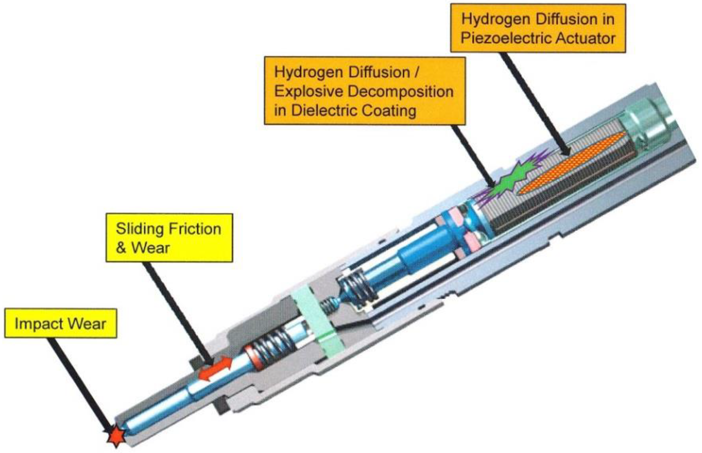
Degradation of the piezoelectric ceramics used to actuate the fuel injectors (hydrogen poisoning and damage due to high-pressure hydrogen uptake);
-
Sliding friction and wear of the injector materials (between the needle guide part and the nozzle body);
-
Degradation due to hydrogen diffusion into the dielectric coating or piezoelectric actuator;
-
Possible epoxy (dielectric) breakdown due to elevated temperatures, hydrogen pressure, or during depressurization.
Impact wear occurs at the contacting surfaces conical needle tip/seat in the fuel nozzle. These components are subject to impact wear as a result of the impacts of the injector needle on the fuel outlet socket, during its opening and closing. Under real-world conditions, the needle/seat interaction is a case of sliding impact that occurs when the needle contacts the nozzle. This leads to a certain amount of energy being dissipated at the contact points of injector needle and nozzle seat. The contact surface between the needle face and the nozzle seat undergoes a slight plastic deformation during break-in. This occurs until an equilibrium state is reached. The cylindrical surface of the hole in the nozzle enables precise guidance of the injector needle. The friction characteristics, method, and wear rate of metal components depend on several factors. The most important factors are the mechanical and thermochemical treatment of the material, working environment, lubrication, and the growth of surface oxide layers. In the chemically reducing environment of hydrogen, the progressive, wear-induced loss of surface oxides will result in contact with the bare surface. This results in increases in the friction and wear [109]. Another type of damage is the appearance of air bubbles preceding the delamination of the epoxy coating covering the piezoelectric stack. Previous studies have shown that the epoxy material is susceptible to hydrogen diffusion. This results in decompression damage upon pressure relief. A further possible consequence of epoxy damage is the formation of voids and the micro-arcing and carbon tracks from the damaged epoxy. This can lead to an electrical short between adjacent electrodes in the stack, ultimately causing an internal short circuit [109,136,137]. Furthermore, piezoelectric elements are exposed to can come into contact with hydrogen due to hydrogen permeation into the material lattice. This results in the deterioration of their electrical properties caused by changes in the internal dipole moments in the crystal due to the formation of –OH bonds. Damage to piezoelectric elements can also be caused by corona discharges on their surface (apparent short circuits [109,120]).
Due to the low lubricating properties of hydrogen, some hydrogen often leaks into the engine combustion chamber due to wear of the injector components. These leaks can cause abnormal combustion processes, such as knocking and flameback, leading to engine stalling. Additionally, the fuel pump powered by liquid hydrogen can fail due to hydrogen gas generation in the compression chamber formed by the cylinder and the pump piston. The generation of hydrogen gas prevents the pump from operating properly, leading to pumping failure. The saturated liquid hydrogen in the fuel tank where the pump is located easily changes to gaseous hydrogen. Even then, a small amount of heat is released due to friction. Friction is also easily created by the moving piston. The higher the delivery pressure, the greater the friction; hence, it is crucial to minimize friction to near zero [99,109].
Future work will address the challenges and problems in the design and optimization of hydrogen-fueled engine systems, subsystems, and components of the H2ICE that differ from the baseline powertrains. With respect to the optimization of combustion and gas exchange as well as the development of emission concepts, depending on the operational strategy pursued by the H2ICE concept (lean-only operation or lean and stoichiometric operation) as well as depending on the powertrain configuration and driving performance requirements, the main research directions and objectives pursued are defined as follows [99,120,123,136,137,138]:
-
Increasing the combustion potential of the lean mixture during a homogeneous combustion process of premixed hydrogen, achievable by further optimizing the charging unit in the heavy load range and adjusting the ignition system for leaner mixtures;
-
Increasing the compression ratio with dedicated combustion chamber design;
-
Optimizing the trade-off between charge motion and cylinder filling;
-
Adjusting the characteristics of the intake port considering the effect of direct fuel injection on the movement of the cargo and the turbulent kinetic energy inside the cylinder, with the simultaneous optimization of the preparation of the combustible mixture;
-
Optimizing H2 PFI and H2DI systems;
-
Optimizing the ignition system;
-
Optimizing the charging system,
-
Applying active temperature management of components with phase-change cooling to reduce the knocking tendency as much as possible and to increase the enthalpy of the exhaust gases, in particular, by actively controlling the temperature of the exhaust manifold;
-
Heavy cooling of the external EGR to lower the intake manifold and high-pressure process temperatures, thus reducing wall heat loss and raw NOx emissions;
-
Developing an emission concept for lean-only as well as lean and stoichiometric operation.
Other challenges arise from the destructive effects of hydrogen on metal parts of the engine and related systems. It is well known that all metals, when in contact with hydrogen, may be susceptible to hydrogen embrittlement. This occurs when atomic hydrogen diffuses into the material, which consequently leads to embrittlement. The phenomenon usually becomes significant when it leads to cracking. Due to the clean burning of hydrogen, almost no oil coke lubrication occurs, which results in a lack of lubrication at tribo-pairs such as valves and valve seats [98,99].
In summary, at this stage of development, hydrogen-powered internal combustion engines still need to overcome numerous challenges [135,136,137,138,139,140]. For example, port fuel injection engines exhibit many limitations. These include including pre-ignition, knock combustion, flameback, low volumetric efficiency, and problems with loss of compression. This limits the allowable load on the engine and its efficiency. A possible solution to these limitations is the use of direct hydrogen injection. Although beneficial, the low compression ratio of typical spark ignition engines limits their thermodynamic efficiency. In compression ignition engines, ignition of the air–fuel mixture may be caused by pilot ignition. This causes the formation of numerous ignition kernels, which promotes the rapid combustion of the gaseous fuel. This combustion mode is known as dual-fuel hydrogen–diesel direct injection and has the potential to reduce the power and compression ratio limitations reported for hydrogen applications in spark ignition engines. However, further research is needed to better understand the mechanisms governing engine performance and pollutant formation in such a dual-fuel combustion mode [130,131,132,133,134,135,136,137,138,139,140].

9. Summary

Hydrogen, as a fuel for internal combustion engines, can significantly contribute to alternative, environmentally friendly road mobility solutions, including meeting the EU’s 2050 CO2 neutrality targets. Hydrogen can be used in both spark ignition as well as compression ignition engines without any major modifications to the existing systems. Hydrogen-powered internal combustion engines with near-zero emissions and higher efficiency than diesel engines are an attractive automotive solution. This solution also takes significant advantage of the mature ICE design. The necessary modifications related to the use of hydrogen as a fuel concern the following engine subsystems and components:
-
Injection system (timed injection is a prerequisite; high flow rate injectors designed for gas are needed both for PFI and DI);
-
Intake manifold (For H2PFI, H2 injectors installation and gas exchange optimization are required);
-
Ignition system (to prevent the occurrence of uncontrolled ignitions due to residual ignition energy, the ignition system must be properly grounded);
-
Spark plugs (cold-rated spark plugs should be used);
-
Cylinder head (cooling optimization to avoid hot spots in the combustion chamber; cooled exhaust valves, new materials for cylinder head, valves, seats, and guides due to risk caused by hydrogen embrittlement and lack of lubrication for clean burning of H2);
-
Piston and piston rings (for reduced oil consumption, to minimize blow-by and H2 leak to the sump, and for crevice volumes reduction);
-
Crank train (risk of engine lubricating oil ageing and washing effects with wear impact and corrosion related issues);
-
Combustion chamber (due to the high flame speeds of hydrogen, a low turbulence combustion chamber should be used; this solution is beneficial for engine efficiency);
-
Compression ratio (optimal compression ratio adapted for hydrogen combustion);
-
Turbocharging (H2-specialized turbocharging system for lower boost pressure demand);
-
Aftertreatment system (optimized for H2 combustion and NOx emissions);
-
Crankcase ventilation system (to limit hydrogen leakage into the crankcase and to avoid critical, ignitable mixtures);
-
Lubrication (engine lubricating oil should be adapted to the increased concentration of water in the crankcase) and an ashless oil to avoid deposit formation and formation hot spots, and an improved blow-by separator.
Hydrogen-fueled internal combustion engines have considerable potential for increasing efficiency: the wide flammability limits and high flame velocity of hydrogen–air mixtures allow various load control strategies, and the high autoignition temperature allows increased compression ratios. Current research works on advanced hydrogen-fueled ICEs have focused on achieving brake thermal efficiency higher than 45% while keeping the levels of NOx emissions low. To accomplish this goal, modern hydrogen-fueled ICEs use direct injection (DI) fueling strategies. This results in increased volumetric efficiency and mitigates issues of knock, pre-ignition, and backfire, which are all negative effects associated with hydrogen port fuel injection. However, DI requires the precise control of air/fuel mixing during the compression stroke such that optimal fuel stratification can be obtained at ignition.
The operation and widespread adoption of internal combustion engines running on hydrogen fuel pose several challenges, the most important of which are:
-
Cylinder head adaptation for injectors;
-
Turbo charger for lower pressure demand;
-
Combustion irregularities;
-
Early pre-ignition;
-
Late pre-ignition;
-
Knocking;
-
Optimization of the mixture formation in the cylinder;
-
Oil input into the combustion chamber;
-
Piston rings and crevice volumes;
-
Optimal compression ratio;
-
Optimizing injection strategies to improve engine efficiency, emissions, and power density;
-
Load control strategies;
-
Degradation and damage of piezoelectric injectors;
-
Maximum reduction in adhesive wear and leakage between the needle and seat with age;
-
Counteracting hydrogen diffusion into a dielectric shell or piezoelectric actuator;
-
Delamination of dielectric epoxy coating;
-
Piezoelectric surface blistering;
-
Actuator cracking due to unwanted tensile loads;
-
Sliding friction and wear of moving parts of injectors;
-
Durability of valves and spark plugs;
-
Hydrogen slip into crankcase;
-
High oil consumption.
The widespread introduction of hydrogen combustion engines into serial production has not yet begun, primarily because the hydrogen infrastructure that is required for all hydrogen-powered vehicles (i.e., fuel cell electric motors as well as hydrogen-fueled internal combustion engines) is underdeveloped. With the construction of H2 infrastructure planned and already underway in some markets, whether and how hydrogen-powered internal combustion engines can complement fuel cells to contribute to CO2-free propulsion systems are currently being discussed. Examples of arguments in favor of hydrogen-fueled internal combustion engines include low investment due to extensive use of existing production capacity and vehicle architecture to date as well as long service life. Furthermore, hydrogen-fueled ICEs can be integrated with electric motors in electrified powertrains (in hybrid powertrains). In addition to the advantages in terms of efficiency and driving range, this leads to attractive functional synergies and additional degrees of freedom in terms of design and operating strategies to be considered.

Funding

This research received no external funding.

Institutional Review Board Statement

Not applicable.

Informed Consent Statement

Not applicable.

Data Availability Statement

Not applicable.

Conflicts of Interest

The authors declare no conflict of interest.

References

  1. Hosseini, S.E.; Butler, B. An overview of development and challenges in hydrogen-powered vehicles. Int. J. Green Energy 2020, 17, 13–37. [Google Scholar] [CrossRef] [Green Version]
  2. Elnashaie, S.; Chen, Z.; Prasad, P. Efficient Production and Economics of Clean-Fuel Hydrogen. Int. J. Green Energy 2007, 4, 249–282. [Google Scholar] [CrossRef]
  3. Hosseini, S.E.; Wahid, M.A.; Ganjehkaviri, A. An overview of renewable hydrogen production from thermochemcial process of oil palm solid waste in Malaysia. Energy Convers. Manag. 2015, 94, 415–429. [Google Scholar] [CrossRef]
  4. Balat, M. Potential importance of hydrogen as a future solution to environmental and transportation problems. Int. J. Hydrogen Energy 2008, 33, 4013–4029. [Google Scholar] [CrossRef]
  5. Dougherty, W.; Kartha, S.; Rajan, C.; Lazarus, M.; Bailie, A.; Runkle, B.; Fencl, A. Greenhouse gas reduction benefits and costs of a large-scale transition to hydrogen in the USA. Energy Policy 2008, 37, 56–67. [Google Scholar] [CrossRef]
  6. Yip, H.L.; Srna, A.; Chun Yin Yuen, A.; Kook, S.; Taylor, R.A.; Heng Yeoh, G.; Medwell, P.R.; Chan, Q.N. A review of hydrogen direct injection for internal combustion engines: Towards carbon-free combustion. Appl. Sci. 2019, 9, 4842. [Google Scholar] [CrossRef] [Green Version]
  7. Hänggi, S.; Elbert, P.; Bütler, T.; Cabalzar, U.; Teske, S.; Bach, C.; Onder, C. A review of synthetic fuels for passenger vehicles. Energy Rep. 2019, 5, 555–569. [Google Scholar] [CrossRef]
  8. Helmolt, R.V.; Eberle, U. Fuel cell vehicles: Status. J. Power Sources 2007, 165, 833–843. [Google Scholar] [CrossRef]
  9. Verhelst, S. Recent progress in the use of hydrogen as a fuel for internal combustion engines. Int. J. Hydrogen Energy 2014, 39, 1071–1085. [Google Scholar] [CrossRef] [Green Version]
  10. White, C.M.; Steeper, R.R.; Lutz, A.E. The hydrogen-fueled internal combustion engine: A technical review. Int. J. Hydrogen Energy 2006, 31, 1292–1305. [Google Scholar]
  11. Al-baghdadi, M. An overview of hydrogen as an alternative fuel. Encyclopedia 2020. Available online: https://encyclopedia.pub/revision/9798/v1 (accessed on 12 June 2021).
  12. Shelef, M.; Kukkonen, C. Prospects of hydrogen-fueled vehicles. Prog. Energy Combust. Sci. 1994, 20, 139. [Google Scholar] [CrossRef]
  13. Eichlseder, H.; Wallner, T.; Freymann, R.; Ringler, J. The Potential of Hydrogen Internal Combustion Engines in a Future Mobility Scenario; SAE International: Warrendale, PA, USA, 2003. [Google Scholar]
  14. Wimmer, A.; Wallner, T.; Ringler, J.; Gerbig, F. H2-Direct Injection—A Highly Promising Combustion Concept; SAE International: Warrendale, PA, USA, 2005. [Google Scholar]
  15. Verhelst, S.; Sierens, R.; Verstraeten, S. A Critical Review of Experimental Research on Hydrogen-Fueled SI Engines; SAE International: Warrendale, PA, USA, 2006. [Google Scholar]
  16. Verhelst, S.; Wallner, T. Hydrogen-fueled internal combustion engines. Prog. Energy Combust. Sci. 2009, 35, 490–527. [Google Scholar] [CrossRef] [Green Version]
  17. Kawamura, A.; Yanai, T.; Sato, Y.; Naganuma, K.; Yamane, K.; Takagi, Y. Summary and Progress of the Hydrogen ICE Truck Development Project; SAE International: Warrendale, PA, USA, 2009; SAE paper no. 2009-01-1922. [Google Scholar]
  18. Kawamura, A.; Sato, Y.; Naganuma, K.; Yamane, K.; Takagi, Y. Development Project of a Multi-Cylinder DISI Hydrogen ICE System for Heavy Duty Vehicles; SAE International: Warrendale, PA, USA, 2010; SAE paper no. 2010-01-2175. [Google Scholar]
  19. Obermair, H.; Scarcelli, R.; Wallner, T. Eciency Improved Combustion System for Hydrogen Direct Injection Operation; SAE International: Warrendale, PA, USA, 2010; SAE paper no. 2010-01-2170. [Google Scholar]
  20. Wallner, T.; Matthias, N.S.; Scarcelli, R.; Kwon, J.C. Evaluation of the efficiency and the drive cycle emissions for a hydrogen direct-injection engine. Proc. Inst. Mech. Eng. Part D J. Automob. Eng. 2012, 227, 99–109. [Google Scholar] [CrossRef]
  21. Verhelst, S.; Maesschalck, P.; Rombaut, N.; Sierens, R. Increasing the power output of hydrogen internal combustion engines by means of supercharging and exhaust gas recirculation. Int. J. Hydrogen Energy 2009, 34, 4406–4412. [Google Scholar] [CrossRef] [Green Version]
  22. Heindl, R.; Eichlseder, H.; Spuller, C.; Gerbig, F.; Heller, K. New and Innovative Combustion Systems for the H2-ICE: Compression Ignition and Combined Processes; SAE International: Warrendale, PA, USA, 2009; SAE paper no. 2009-01-1421. [Google Scholar]
  23. Welch, A.; Mumford, D.; Munshi, S.; Holbery, J.; Boyer, B.; Younkins, M.; Jung, H. Challenges in Developing Hydrogen Direct Injection Technology for Internal Combustion Engines; SAE International: Warrendale, PA, USA, 2008; SAE Paper no. 2008-01-2379. [Google Scholar]
  24. Sopena, C.; Dieguez, P.; Sainz, D.; Urroz, J.; Guelbenzu, E.; Gandía, L.M. Conversion of a commercial spark ignition engine to run on hydrogen: Performance comparison using hydrogen and gasoline. Int. J. Hydrogen Energy 2010, 35, 1420–1429. [Google Scholar] [CrossRef]
  25. Yamane, K. Hydrogen-Fueled ICE, Successfully Overcoming Challenges through High-Pressure Direct Injection Technologies: 40 Years of Japanese Hydrogen ICE Research and Development; SAE International: Warrendale, PA, USA, 2018; No. 2018-01-1145. [Google Scholar] [CrossRef]
  26. Walter, L.; Sommermann, A.; Hyna, D.; Malischewski, T.; Leistner, M.; Hinrichsen, F.; Wöhner, P.; Schmitt, J.; McMackin, M. The H2 combustion engine—the forerunner of a zero emissions future. In Proceedings of the 42nd International Vienna Motor Symposium, Vienna, Austria, 29–30 April 2021. [Google Scholar]
  27. Korn, T.; Nobile, R.-F.; Grassinger, D. Zero-emission, maximum performance—the latest generation of hydrogen combustion engines. In Proceedings of the 42nd International Vienna Motor Symposium, Vienna, Austria, 29–30 April 2021. [Google Scholar]
  28. Pauer, T.; Weller, H.; Schünemann, E.; Eichlseder, H.; Grabner, P.; Schaffer, K. H2 ICE für zukünftige PKWs und leichte Nutzfahrzeuge. In Proceedings of the 41st Internationales Wiener Motorensymposium, Vienna, Austria, 22–24 April 2020. [Google Scholar]
  29. Boretti, A. Transient positive ignition internal combustion engines have now surpassed the 50% fuel conversion efficiency barrier. Int. J. Hydrogen Energy 2019, 44, 7051–7052. [Google Scholar] [CrossRef]
  30. Das, L.M. Hydrogen engines: A view of the past and a look into the future. Int. J. Hydrogen Energy 1990, 15, 425–443. [Google Scholar] [CrossRef]
  31. Glaude, P.A.; Fournet, R.; Bounaceur, R.; Molière, M. Adiabatic flame temperature from biofuels and fossil fuels and derived effect on NOx emissions. Fuel Process Technol. 2010, 91, 229–235. [Google Scholar] [CrossRef]
  32. Chong, C.T.; Hochgreb, S. Measurements of laminar flame speeds of liquid fuels: Jet-A1, diesel, palm methylesters and blends using particle-imaging velocimetry (PIV). Proc. Combust. Inst. 2011, 33, 979–986. [Google Scholar] [CrossRef]
  33. Srinivasana, C.B.; Subramanian, R. Hydrogen as a spark ignition engine fuel technical review. Int. J. Mech. Mechatron. Eng. IJMME-IJENS 2014, 14, 111–117. [Google Scholar]
  34. Dimitriou, P.; Tsujimura, T. A review of hydrogen as a compression ignition engine fuel. Int. J. Hydrogen Energy 2017, 42, 24470–24486. [Google Scholar] [CrossRef]
  35. Kumar, N. Hydrogen use in internal combustion engine. Int. J. Adv. Cult. Technol. 2015, 2, 87–99. [Google Scholar]
  36. Faizal, M.; Chuah, L.S.; Lee, C.; Hameed, A.; Lee, J.; Shankar, M. Review of hydrogen fuel for internal combustion engines. J. Mech. Eng. Res. Dev. (JMERD) 2019, 42, 35–46. [Google Scholar]
  37. Molnarne, M.; Schendler, T.; Schroeder, V. Sicherheitstechnische Kenngroessen, Band 2: Explosionsbereiche von Gasgemischen. In Wirtschaftsverlag NW—Verlag fuer neue Wissenschaft; 2003. [Google Scholar]
  38. Schroeder, V.; Holtappels, K. Explosion characteristics of hydrogen-air and hydrogen-oxygen mixtures at elevated pressures. In Proceedings of the International Conference on Hydrogen Safety, Pisa, Italy, 8–10 September 2005. Paper No. 120001. [Google Scholar]
  39. Subash, G.P.; Das, L.M. An experimental investigation on the performance and emission characteristics of a hydrogen fueled spark ignition engine. Int. J. Sci. Technol. Manag. 2011, 8, 197–208. [Google Scholar]
  40. Karim, G.A. Hydrogen as a spark ignition engine fuel. Chem. Ind. 2002, 6, 256–263. [Google Scholar] [CrossRef] [Green Version]
  41. Ono, R.; Nifuku, M.; Fujiwara, S.; Horiguchi, S.; Oda, T. Minimum ignition energy of hydrogen-air mixture: Effects of humidity and spark duration. J. Electrost. 2007, 65, 87–93. [Google Scholar] [CrossRef]
  42. Gandhi, R.D. Use of hydrogen in internal combustion engine. Int. J. Eng. Manag. Sci. (IJEMS) 2015, 3, 207–216. [Google Scholar]
  43. Ciniviz, M.; Kose, H. Hydrogen use in internal combustion engine. Int. J. Automot. Eng. Technol. 2012, 18, 1–15. [Google Scholar]
  44. Hong, S.-W.; Shin, Y.-S.; Song, J.-H.; Chang, S.-H. Performance test of the quenching meshes for hydrogen control. J. Nucl. Sci. Technol. 2003, 40, 814–819. [Google Scholar] [CrossRef]
  45. Potter, A.E., Jr. Flame Quenching, Progress in Combustion and Fuel Technology; Durcarme, J., Gerstain, M., Lefebvre, A.H., Eds.; Pergamon Press: New York, NY, USA, 1960; Volume 1, p. 5182. [Google Scholar]
  46. Korn, T. The Most Efficient Way for CO2 Reduction: The New Generation of Hydrogen Internal Combustion Engines. In Proceedings of the 41th International Vienna Motoren Symposium, Vienna, Austria, 22–24 April 2020. [Google Scholar]
  47. Wahab, A.M. Addition of hydrogen to gasoline-fueled 4 stroke SI engine using 1-dımensıonal analysis. In Faculty of Mechanical Engineering; University Malaysia Pahang: Pahang, Malaysia, 2009; pp. 1–68. [Google Scholar]
  48. Maher, A.R. Sadiq Al-Baghdadi. Alternative fuels research progress. In International Energy and Environment Foundation; Maher, A.R., Al-Baghdadi, S., Eds.; 2013; 442p, ISBN 9781484057711. [Google Scholar]
  49. Aleiferis, P.G.; Rosati, M.F. Controlled autoignition of hydrogen in a direct-injection optical engine. Combust. Flame 2012, 159, 2500–2515. [Google Scholar] [CrossRef] [Green Version]
  50. Ingersoll, J.G. Natural Gas Vehicles; Fairmont Press: Lilburn, GA, USA, 1996. [Google Scholar]
  51. Mazloomi, K.; Gomes, C. Hydrogen as an energy carrier: Prospects and challenges. Renew. Sustain. Energy Rev. 2012, 16, 3024–3033. [Google Scholar] [CrossRef]
  52. Heffel, J.W. NOx emission and performance data for a hydrogen-fueled internal combustion engine at 1500 rpm using exhaust gas recirculation. Int. J. Hydrogen Energy 2003, 28, 901–908. [Google Scholar] [CrossRef]
  53. Acar, C.; Dincer, I. The potential role of hydrogen as a sustainable transportation fuel to combat global warming. Int. J. Hydrogen Energy 2018, 45, 3396–3406. [Google Scholar] [CrossRef]
  54. Bradley, D.M.; Lawes, K.; Liu, S.; Verhelst, S.; Woolley, R. Laminar burning velocities of lean hydrogen–Air mixtures at pressures up to 1.0 MPa. Combust. Flame 2006, 149, 162–172. [Google Scholar] [CrossRef]
  55. Luo, Q.; Sun, B. Inducing factors and frequency of combustion knock in hydrogen internal combustion engines. Int. J. Hydrogen Energy 2016, 41, 16296–16305. [Google Scholar] [CrossRef]
  56. Verhelst, S.; Sierens, R. Aspects concerning the optimization of a hydrogen-fueled engine. Int. J. Hydrogen Energy 2001, 26, 981–985. [Google Scholar] [CrossRef]
  57. Negurescu, N.; Pana, C.; Cernat, A. Aspects of using hydrogen in SI engine. Univ. " Politeh. " Buchar. Sci. Bull. Ser. D Mech. Eng. 2012, 74, 11–20. [Google Scholar]
  58. Abdelghaffar, W.A. Spark ignition engine fueled by Hydrogen: Comparative analysis. Eur. J. Sci. Res. 2010, 44, 13–28. [Google Scholar]
  59. Suryawanshi, J.G.; Nitnaware, P.T. An investigation on SI engine using Hydrogen and CNG blends. IJRRAS 2011, 7, 295–303. [Google Scholar]
  60. Szwaja, S.; Grab-Rogalinski, K. Hydrogen combustion in a compression ignition diesel engine. Int. J. Hydrogen Energy 2009, 34, 4413–4421. [Google Scholar] [CrossRef]
  61. Saravanan, N.; Nagarajan, G.; Sanjay, G.; Dhanasekaran, C.; Kalaiselvan, M.K. Combustion analysis on a DI diesel engine with hydrogen in dual fuel mode. Fuel 2008, 87, 3591–3599. [Google Scholar] [CrossRef]
  62. Gomes Antunes, J.M.; Mikalsen, R.; Roskilly, A.P. An experimental study of a direct injection compression ignition hydrogen engine. Int. J. Hydrogen Energy 2009, 34, 6516–6522. [Google Scholar] [CrossRef]
  63. Naber, J.D.; Siebers, D.L. Hydrogen combustion under diesel engine conditions. Int. J. Hydrogen Energy 1998, 23, 363–371. [Google Scholar] [CrossRef]
  64. Saravanan, N.; Nagarajan, G. Performance and emission studies on port injection of hydrogen with varied flow rates with Diesel as an ignition source. Appl. Energy 2010, 87, 2218–2229. [Google Scholar] [CrossRef]
  65. Korakianitis, T.; Namasivayam, M.A.; Crookes, J.R. Hydrogen dual-fueling of compression ignition engines with emulsified biodiesel as pilot fuel. Int. J. Hydrogen Energy 2010, 35, 13329–13344. [Google Scholar] [CrossRef]
  66. Kirchweger, W. Applications of the LIF method for the diagnostics of the combustion process of gas-IC-engines. Exp. Fluids 2007, 43, 329–340. [Google Scholar] [CrossRef]
  67. Lee, S.J.; Yi, H.S.; Kim, E.S. Combustion characteristics of intake port injection type hydrogen-fueled engine. Hydrogen Energy 1995, 20, 317–322. [Google Scholar] [CrossRef]
  68. Liu, X.H. Backfire prediction in a manifold injection hydrogen internal combustion engine. Int. J. Hydrogen Energy 2008, 33, 3847–3855. [Google Scholar] [CrossRef]
  69. Verhelst, S.; Verstraeten, S.; Sierens, R. A comprehensive overview of hydrogen engine design features. Proc. Inst. Mech. Eng. Part D J. Automob. Eng. 2007, 221, 911–919. [Google Scholar] [CrossRef]
  70. Saravanan, N.; Nagarajan, G.; Dhanasekaran, C.; Kalaiselvan, K. Experimental investigation of hydrogen port fuel injection in DI diesel engine. Int. J. Hydrogen Energy 2007, 32, 4071–4080. [Google Scholar] [CrossRef]
  71. Leiker, M.; Cartelliere, W.; Christoph, H.; Pfeifer, U.; Rankl, M. Evaluation of anti-knocking property of gaseous fuels by means of methane number and its practical application to gas engines. ASME 1972, 94, 55. [Google Scholar]
  72. Li, H.; Karim, G.A. Hydrogen-fueled spark-ignition engines predictive and experimental performance. Trans. ASME J. Eng. Gas Turbines Power 2006, 128, 230–236. [Google Scholar] [CrossRef]
  73. Kleijn, R.; Van der Voet, E. Resource constraints in a hydrogen economy based on renewable energy sources: An exploration. Renew. Sustain. Energy Rev. 2010, 14, 2784–2795. [Google Scholar] [CrossRef]
  74. Szwaja, S.; Bhandary, K.; Naber, J. Comparisons of hydrogen and gasoline combustion knock in a spark ignition engine. Int. J. Hydrogen Energy 2007, 32, 5076–5087. [Google Scholar] [CrossRef]
  75. Verhelst, S.; Sierens, R.; Scarcelli, R. Update on the progress of hydrogen-fueled internal combustion engines. Renew. Hydrogen Technol. 2013, 381–400. [Google Scholar] [CrossRef] [Green Version]
  76. Li, H.; Karim, G.A. Knock in spark ignition hydrogen engines. Int. J. Hydrogen Energy 2004, 29, 859–865. [Google Scholar] [CrossRef]
  77. Sadiq Al-Baghdadi Maher, A.R. Effect of compression ratio, equivalence ratio and engine speed on the performance and emission characteristics of a spark ignition engine using hydrogen as a fuel. Renew. Energy 2004, 29, 2245–2260. [Google Scholar] [CrossRef]
  78. Saxena, R.C. Thermo-chemical routes for hydrogen rich gas from biomass: A review. Renew. Sustain. Energy Rev. 2008, 12, 1909–1927. [Google Scholar] [CrossRef]
  79. Bardon, M.F.; Haycock, R.G. The hydrogen research of R. In O. King. In Proceedings of the 14th World Hydrogen Energy Conference, Montreal, QC, Canada, 9–13 June 2002; p. 22, invited paper. [Google Scholar]
  80. MacCarley, C.A. A study of factors influencing thermally induced backfiring in hydrogen-fueled engines, and methods for backfire control. In Proceedings of the Intersociety Energy Conversion Engineering Conference, Atlanta, GA, USA, 9 August 1981; p. 5. [Google Scholar]
  81. Das, L.M. Near-term introduction of hydrogen engines for automotive and agricultural application. Int. J. Hydrogen Energy 2002, 27, 479–487. [Google Scholar] [CrossRef]
  82. Lucas, G.G.; Morris, L.E. The backfire problem of the hydrogen engine. In Proceedings of the Symposium Organized by the University’s Internal Combustion Engine Group, King’s College, London, UK, 1980. [Google Scholar]
  83. Das, L.M. Hydrogen–oxygen reaction mechanism and its implication to hydrogen engine combustion. Int. J. Hydrogen Energy 1996, 21, 703–715. [Google Scholar] [CrossRef]
  84. Berckmüller, M.; Rottengruber, H.; Eder, A.; Brehm, N.; Elsasser, G.; Müller-Alander, G.; Schwarz, C. Potentials of a Charged SI-Hydrogen Engine; SAE International: Warrendale, PA, USA, 2003; SAE paper 2003-01-3210. [Google Scholar]
  85. Stockhausen, W.F.; Natkin, R.J.; Kabat, D.M.; Reams, L.; Tang, X.; Hashemi, S.; Szwabowski, S.J.; Zanardelli, V.P. Ford P2000 Hydrogen Engine Design and Vehicle Development Program; SAE International: Warrendale, PA, USA, 2002; SAE paper 2002-01-0240. [Google Scholar]
  86. Swain, M.R.; Swain, M.N.; Adt, R.R. Consideration in the Design of an Inexpensive Four Hydrogen-Fueled Engine; SAE International: Warrendale, PA, USA, 1988; SAE paper 881630. [Google Scholar]
  87. Kondo, T.; Iio, S.; Hiruma, M. A Study on the Mechanism of Backfire in External Mixture Formation Hydrogen Engines—About Backfire Occurred by the Cause of the Spark Plug; SAE International: Warrendale, PA, USA, 1997; SAE paper 971704. [Google Scholar]
  88. Lee, J.T.; Kim, Y.Y.; Lee, C.W.; Caton, J.A. An investigation of a cause of backfire and its control due to crevice volumes in a hydrogen-fueled engine. In Proceedings of the ASME Spring Technical Conference, San Antonio, TX, USA, 2000. paper 2000-ICE-284 (American Society of Mechanical Engineers, New York). [Google Scholar]
  89. Verhelst, S.; Demuynck, J.; Sierens, R.; Huyskens, P. Impact of variable valve timing on power, emissions and backfire of a bi-fuel hydrogen/gasoline engine Inter. J. Hydr. Ener 2010, 35, 4399–4408. [Google Scholar] [CrossRef] [Green Version]
  90. Office of Energy Efficiency & Renewable Energy. Hydrogen Use in Internal Combustion Engines. 2020. Available online: http://www.eere.energy.gov (accessed on 27 September 2021).
  91. Shudo, T.; Omori, K.; Hiyama, O. NOx reduction and NO2 emission characteristics in rich-lean combustion of hydrogen. Int. J. Hydrogen Energy 2008, 33, 4689–4693. [Google Scholar] [CrossRef] [Green Version]
  92. Das, L.M. Hydrogen engine: Research and development (R&D) programmers in Indian Institute of Technology (IIT), Delhi. Int. J. Hydrogen Energy 2002, 27, 953–965. [Google Scholar]
  93. Masood, M.; Ishrat, M.M.; Reddy, S.A. Computational combustion and emission analysis of hydrogen–diesel blends with experimental verification. Int. J. Hydrogen Energy 2007, 32, 2539–2547. [Google Scholar] [CrossRef]
  94. Verhelst, S.; Sierens, R. Hydrogen engine-specific properties. Int. J. Hydrogen Energy 2001, 26, 987–990. [Google Scholar] [CrossRef]
  95. Lucas, G.G.; Emtage, A.L. Microprocessor control of the hydrogen/petrol engine. IMechE 1987, 231–240, paper no. C08/87. [Google Scholar]
  96. Ikegami, M.; Miwa, K.; Shioji, M. A study of hydrogen-fueled compression ignition engines. Int. J. Hydrogen Energy 1982, 7, 341–353. [Google Scholar] [CrossRef]
  97. Maccarley, C.A.; Van Vorst, W.D. Electronic fuel injection techniques for hydrogen-powered I.C. engines. Int. J. Hydrogen Energy 1980, 5, 179–203. [Google Scholar] [CrossRef] [Green Version]
  98. Kufferath, A.; Schünemann, E.; Krüger, M.; Krüger, M.; Jianye, S.; Eichlseder, H.; Koch, T. H2 ICE Powertrains for future on-road mobility. In Proceedings of the 42nd International Vienna Motor Symposium, Vienna, Austria, 29–30 April 2021. [Google Scholar]
  99. Pauer, T.; Weller, H.; Schünemann, E.; Eichlseder, H.; Grabner, P.; Schaffer, K. H2 ICE for future passenger cars and light commercial vehicles. In Proceedings of the 41st International Vienna Motor Symposium, Vienna, Austria, 22–24 April 2020. [Google Scholar]
  100. Welch, A.; Mumford, D.; Munshi, S.; Holbery, J.; Boyer, B. Hydrogen direct injection technology—challenges and opportunities. In Proceedings of the NHA Annual Hydrogen Conference 2008, Sacramento, CA, USA, 31 March–4 April 2008; Available online: https://nha.confex.com/nha/2008/techprogram/P4181.HTM (accessed on 27 September 2021).
  101. Sun, B.-G.; Zhang, D.-S.; Liu, F.-S. Cycle variations in a hydrogen internal combustion engine. Int. J. Hydrogen Energy 2013, 38, 3778–3783. [Google Scholar] [CrossRef]
  102. Salazar, V.; Kaiser, S. Interaction of Intake-Induced Flow and Injection Jet in a Direct-Injection Hydrogen-Fueled Engine Measured by PIV; SAE International: Warrendale, PA, USA, 2011; No. 2011-01-0673. [Google Scholar] [CrossRef]
  103. Chand, M.A.; Monga, R. Optimization of hydrogen direct injection engine to reduce NOx emissions. Int. J. Innov. Sci. Res. 2014, 1, 63–66. [Google Scholar]
  104. Wallner, T.; Ciatti, S.; Bihari, B.; Stockhausen, W.; Boyer, B. Endoscopic investigations in a hydrogen internal combustion engine. In Proceedings of the 1st International Symposium on Hydrogen Internal Combustion Engines, Graz, Austria, 2006. [Google Scholar]
  105. Boretti, A. Hydrogen internal combustion engines to 2030. Int. J. Hydrogen Energy 2020, 45, 23692–23703. [Google Scholar] [CrossRef]
  106. Boretti, A.; Watson, H.; Tempia, A. Computational analysis of the lean-burn direct-injection jet ignition hydrogen engine. Proc. Inst. Mech. Eng. Part D J. Automob. Eng 2010, 224, 261–269. [Google Scholar] [CrossRef]
  107. Mumford, D.; Welch, A.; Bartunek, B. Development of H2 direct injection technology for High efficiency/high BMEP engines. In Proceedings of the 1st International Symposium on Hydrogen Internal Combustion Engines, Graz, Austria, 2006. [Google Scholar]
  108. Eichlseder, H.; Grabner, P.; Gerbig, F.; Heller, K. Advanced combustion concepts and development methods for hydrogen IC engines. In FISITA World Automotive Congress; GWV Fachverlage GmbH: Munich, Germany, 2008. [Google Scholar]
  109. Gerbig, F.; Strobl, W.; Eichlseder, H.; Wimmer, A. Potentials of the hydrogen combustion engine with innovative hydrogen–specific combustion process. In FISITA World Automotive Congress; GWV Fachverlage GmbH: Munich, Germany, 2004. [Google Scholar]
  110. Wallner, T. Entwicklung von Brennverfahrenskonzepten für Einen Pkw–Motor mit Wasserstoffbetrieb (Development of Combustion Concepts for a Hydrogen-Powered Internal Combustion Engine). PHD Dissertation, TU Graz, Graz, Austria, 2004. [Google Scholar]
  111. Ikegami, M.; Miwa, K.; Shioji, M.; Esaki, M. A study on hydrogen-fueled diesel combustion. Bull JSME 1980, 23, 1187–1193. [Google Scholar] [CrossRef] [Green Version]
  112. Varde, K.S.; Frame, G.A. Hydrogen aspiration in a direct injection type diesel engine—its effects on smoke and other engine performance parameters. Int. J. Hydrogen Energy 1983, 8, 549–555. [Google Scholar] [CrossRef] [Green Version]
  113. Lilik, G.K.; Zhang, H.; Herreros, J.M.; Haworth, D.C.; Boehman, A.L. Hydrogen-assisted diesel combustion. Int. J. Hydrogen Energy 2010, 35, 4382–4398. [Google Scholar] [CrossRef]
  114. Santoso, W.B.; Bakar, R.A.; Nur, A. Combustion characteristics of diesel-hydrogen dual fuel engine at low load. Energy Procedia 2013, 32, 3–10. [Google Scholar] [CrossRef] [Green Version]
  115. Suzuki, Y.; Tsujimura, T. The Combustion Improvements of Hydrogen/Diesel Dual Fuel Engine, SAE Technical Paper. 2015; No. 2015-01-1939.
  116. Suzuki, Y.; Tsujimura, T.; Mita, T. The performance of multi-cylinder hydrogen/diesel dual fuel engine. SAE Int. J. Engines 2015, 8, 2240–2252. [Google Scholar] [CrossRef]
  117. Karagoz, Y.; Sandalci, T.; Yuksek, L.; Dalkilic, A.S. Engine performance and emission effects of diesel burns enriched by hydrogen on different engine loads. Int. J. Hydrogen Energy 2015, 40, 6702–6713. [Google Scholar] [CrossRef]
  118. Dreisbach, R.; Arnberger, A.; Zukancic, A.; Wieser, M.; Kunder, N.; Plettenberg, M.; Raser, B.; Eichlseder, H. The heavy-duty hydrogen engine and its realization until 2025. In Proceedings of the 42nd International Vienna Motor Symposium, Vienna, Austria, 29–30 April 2021. [Google Scholar]
  119. Golisano, R.; Scalabrini, S.; Arpaia, A.; Pesce, F.; Vassallo, A.; Borgia, L.; Cubito, C.; Biasin, V.; Knichel, T.; Millo, F.; et al. PUNCH Hydrogen internal combustion engine & KERS: An appealing value-proposition for green power pack. In Proceedings of the 42nd International Vienna Motor Symposium, Vienna, Austria, 29–30 April 2021. [Google Scholar]
  120. Sens, M.; Danzer, C.; von Essen, C.; Brauer, M.; Wascheck, R.; Seebode, J.; Kratzsch, M. Hydrogen powertrains in competition to fossil fuel-based internal combustion engines and battery electric powertrains. In Proceedings of the 42nd International Vienna Motor Symposium, Vienna, Austria, 29–30 April 2021. [Google Scholar]
  121. Rezaei, R.; Riess, M.; Li, Q.; Rolke, P.; Wohlrab, A.; Hayduk, C.; Bertram, C. Decarbonization of commercial vehicles with hydrogen combustion: From concept to start of production and beyond. In Proceedings of the 2nd World Congress on Internal Combustion Engines, Jinan, China, 21–24 April 2021. [Google Scholar]
  122. Rezaei, R.; Mennig, M.; Hayduk, C.; Bertram, C.; Hahn, C.; Kureti, S. Holistic engine and exhaust after-treatment system development for hydrogen combustion concepts. In Proceedings of the 18th FAD Conference Challenge—Exhaust aftertretament, Radebeul, Dresden, 15–16 September 2020. [Google Scholar]
  123. Rezaei, R.; Hayduk, C.; Sens, M.; Fandakov, A.; Bertram, C. Model-based development methodology for HD hydrogen combustion system optimization. In ATZ Experten-Forum Powertrain 2020—Ladungswechsel und Emissionierung; 2020. [Google Scholar]
  124. Rezaei, R.; Sens, M.; Riess, M.; Bertram, C. Potentials and challenges of hydrogen combustion system development as a sustainable fuel for commercial vehicles. ATZ Engine Conference, Baden-Baden, Germany, 2021. [Google Scholar]
  125. Virnich, L.; Lindemann, B.; Müther, M.; Schaub, J.; Huth, V.; Geiger, J. How to improve transient engine performance of HD hydrogen engines while maintaining lowest NOx Emissions. In Proceedings of the 42nd International Vienna Motor Symposium, Vienna, Austria, 29–30 April 2021. [Google Scholar]
  126. Swain, M.R.; Schade, G.J.; Swain, M.N. Design and Testing of a Dedicated Hydrogen-Fueled Engine, SAE Technical Paper. 1996; SAE paper 961077.
  127. Koyanagi, K.; Hiruma, M.; Furuhama, S. Study on Mechanism of Backfire in Hydrogen Engines, SAE Technical Paper. 1994; SAE paper 942035.
  128. Tang, X.; Stockhausen, W.F.; Kabat, D.M.; Natkin, R.J.; Heffel, J.W. Ford P2000 Hydrogen Engine Dynamometer Development, SAE Technical Paper. 2002; SAE Paper No. 2002-01-0242.
  129. Olavson, L.G.; Baker, N.R.; Lynch, F.E.; Meija, L.C. Hydrogen Fuel for Underground Mining Machinery, SAE Technical Paper. 1984; SAE Paper No. 840233.
  130. Eichlseder, H.; Klell, M.; Sartory, M.; Schaffer, K.; Leitner, D. Potential of Synergies in a Vehicle for Variable Mixtures of CNG and Hydrogen, SAE Technical Paper. 2009; SAE Paper No. 2009-01-1420.
  131. Pitman, S.; Smit, M.; Blau, P.; Boyer, B.; Erdimer, A.; Welch, A. Hydrogen Material Compatibility for Hydrogen ICE. In DOE Sponsored Project DE AC06 76RLO 1830 Propulsion Materials Technology Development Manager: Jerry Gibbs; 2009. Available online: https://www.energy.gov/sites/prod/files/2014/03/f13/pm_04_smith.pdf (accessed on 27 September 2021).
  132. Erdemir, A.; Ozturk, O.; Alzoubi, M.; Woodford, J.; Ajayi, L.; Fenske, G. Near-Frictionless Carbon for Use in Fuel Injectors and Pump systems Operating with Low-Sulfur Diesel Fuels, SAE Technical Paper. 2000; SAE 2000-01-0518.
  133. Yasuda, Y.; Kano, M.; Mabuchi, Y.; Abou, S. Research on Diamond-Like Carbon Coatings for Low-Friction Valve Lifters, SAE Technical Paper. 2003; SAE 2003-01-1101.
  134. Matthias, N.S.; Wallner, T.; Scarcelli, R. A hydrogen direct injection engine concept that exceeds U.S. DOE light-duty efficiency targets. SAE Int. J. Engines 2012, 5, 838–849. [Google Scholar] [CrossRef]
  135. Antunes, J.G.; Mikalsen, R.; Roskilly, A.P. An investigation of hydrogen-fueled HCCI engine performance and operation. Int. J. Hydrogen Energy 2008, 33, 5823–5828. [Google Scholar]
  136. Lee, K.J.; Kim, Y.R.; Byun, C.H.; Lee, J.T. Feasibility of compression ignition for hydrogen-fueled engine with neat hydrogen-air pre-mixture by using high compression. Int. J. Hydrogen Energy 2013, 38, 255–264. [Google Scholar] [CrossRef]
  137. Chintala, V.; Subramanian, K.A. A comprehensive review on utilization of hydrogen in a compression ignition engine under dual fuel mode. Renew. Sustain. Energy Rev. 2017, 70, 472–491. [Google Scholar] [CrossRef]
  138. Sandalcı, T.; Karagöz, Y. Experimental investigation of the combustion characteristics, emissions and performance of hydrogen port fuel injection in a diesel engine. Int. J. Hydrogen Energy 2014, 39, 18480–18489. [Google Scholar] [CrossRef]
  139. Mohammadi, A.; Shioji, M.; Nakai, Y.; Ishikura, W.; Tabo, E. Performance and combustion characteristics of a direct injection SI hydrogen engine. Int. J. Hydrogen Energy 2007, 32, 296–304. [Google Scholar] [CrossRef]
  140. Takagi, Y.; Mori, H.; Mihara, Y.; Kawahara, N.; Tomita, E. Improvement of thermal efficiency and reduction of NOx emissions by burning a controlled jet plume in high-pressure direct-injection hydrogen engines. Int. J. Hydrogen Energy 2017, 42, 26114–26122. [Google Scholar] [CrossRef]
Figure 1. Comparison of ICE and electric motors (BEVs and FCEVs).
Energies 14 06504 g001
Figure 2. Comparison of various injection and ignition strategies [99,104].
Energies 14 06504 g002
Figure 3. Comparison of different hydrogen combustion processes [120].
Energies 14 06504 g003
Figure 4. Areas and types of fuel injector damage [109,136].
Energies 14 06504 g004
Table 1. Comparison of the three zero-emission technologies.
ParametersBattery Electric VehiclesFuel Cell Electric VehiclesH2 Engine Vehicles
Production + infrastructure + operating costs Energies 14 06504 i001
Suitability for daily use Energies 14 06504 i002 Energies 14 06504 i003
Driving Ranges Energies 14 06504 i001 Energies 14 06504 i003 Energies 14 06504 i003
Refueling time Energies 14 06504 i001 Energies 14 06504 i003 Energies 14 06504 i003
Fuel efficiency Energies 14 06504 i003 Energies 14 06504 i003 Energies 14 06504 i002
Durability Energies 14 06504 i002 Energies 14 06504 i001 Energies 14 06504 i003
Climate Protection Energies 14 06504 i002 Energies 14 06504 i003 Energies 14 06504 i003
Table 2. Hydrogen properties compared with gasoline, diesel, and methane [11,15,33,34].
PropertyHydrogenMethaneGasolineDiesel
Carbon content (mass%)0758486
Lower (net) heating value (MJ/kg)119.945.843.942.5
Density (at 1 bar & 273 K; kg/m3)0.0890.72730–780830
Volumetric energy content (at 1 bar & 273 K; MJ/m3)10.733.033 × 10335 × 103
Molecular weight2.01616.043~110~170
Boiling point (K)20111298–488453–633
Auto-ignition temperature (K)853813~623~523
Minimum ignition energy in air (at 1 bar & at stoichiometry; mJ)0.020.290.240.24
Stoichiometry air/fuel mass ratio34.417.214.714.5
Quenching distance (at 1 bar & 298 K at stoichiometry; mm)0.642.1~2-
Laminar flame speed in air (at 1 bar & 298 K at stoichiometry; m/s)1.850.380.37–0.430.37–0.43
Diffusion coefficient in air (at 1 bar & 273 K; m2/s)8.5 × 10−61.9 × 10−6--
Flammability limits in air (vol%)4–765.3–151–7.60.6–5.5
Adiabatic flame temperature (at 1 bar & 298 K at stoichiometry; K)248022142580~2300
Octane number (R+M)/2130+120+86–94-
Cetane number--13–1740–55
Table 3. Comparison of key features and parameters of PFI and DI fuel systems [98].
Features and ParametersIntake ManifoldDirect Injection
Low Pressure DIHigh Pressure DI
H2 injectionPFI single pointPFI open valveSuction & begin of compression strokeNear TDC
Fuel InjectionEquipment costsModerateBest cost/bebefit Trade-offCostly H2 Injection system
Power densityCa. −30% comp. To DieselComparable to Diesel resp. 0 to −20%
EfficiencySlightly below DieselClose to Diesel
Further featuresHigh risk of backfireRisk of backfireH2 LP—system as FCEV, allows high milageH2 compression pump require
Table 4. Advantages of direct injection vs. port fuel injection [99].
Basic AdvantagesRelated to the Injection Process
Power density improvement
Air is not displaced by H2 during intake stroke
Reduced thermal losses with charge stratification
Minimal wall contact with fuel
Elimination of backfire
H2 injection after intake valve closing
Low Nox, multi-injection strategies
Recovery of a portion of tank energy
Ideally inject at TDC
Pressure rise rate control with multi-injection
Reduced pre-ignition tendency
Late injection results in less compression heating, incylinder residance time and exposure to hot spots
Improved thermal efficiency
Increased compression ratio potential
Publisher’s Note: MDPI stays neutral with regard to jurisdictional claims in published maps and institutional affiliations.

