
Liquid Hydrogen: A Review on Liquefaction, Storage, Transportation, and Safety


Institute of Industrial Science, The University of Tokyo, Tokyo 153-8505, Japan
Energies 2021, 14(18), 5917; https://doi.org/10.3390/en14185917
Submission received: 3 June 2021
/
Revised: 28 July 2021
/
Accepted: 18 August 2021
/
Published: 17 September 2021
(This article belongs to the Collection Hydrogen Energy Reviews)
Abstract
:Decarbonization plays an important role in future energy systems for reducing greenhouse gas emissions and establishing a zero-carbon society. Hydrogen is believed to be a promising secondary energy source (energy carrier) that can be converted, stored, and utilized efficiently, leading to a broad range of possibilities for future applications. Moreover, hydrogen and electricity are mutually converted, creating high energy security and broad economic opportunities toward high energy resilience. Hydrogen can be stored in various forms, including compressed gas, liquid hydrogen, hydrides, adsorbed hydrogen, and reformed fuels. Among these, liquid hydrogen has advantages, including high gravimetric and volumetric hydrogen densities and hydrogen purity. However, liquid hydrogen is garnering increasing attention owing to the demand for long storage periods, long transportation distances, and economic performance. This paper reviews the characteristics of liquid hydrogen, liquefaction technology, storage and transportation methods, and safety standards to handle liquid hydrogen. The main challenges in utilizing liquid hydrogen are its extremely low temperature and ortho- to para-hydrogen conversion. These two characteristics have led to the urgent development of hydrogen liquefaction, storage, and transportation. In addition, safety standards for handling liquid hydrogen must be updated regularly, especially to facilitate massive and large-scale hydrogen liquefaction, storage, and transportation.
1. Introduction
The increase in atmospheric greenhouse gas (GHGs) concentrations has raised concern regarding climate change, which is currently regarded as the largest global issue that needs to be urgently mitigated. In 2019, the total carbon emitted from the energy-related sector was approximately 33 Gt-CO2 [1], approximately 87% of the total globally emitted CO2. Moreover, this value is predicted to increase due to increasing global energy consumption. The Kyoto Protocol [2], which was signed by 192 countries and entered into force in 2005, was an organized global effort to combat climate change. This effort was followed by the Paris Agreement [3] in 2015, which aimed to limit the global average temperature increase to under 2 °C while actively attempting to limit this increase to 1.5 °C. The strategy to establish a low-carbon energy system is believed to be crucial for reducing GHG emissions. Several evident efforts have been proposed, including reducing fossil fuel consumption, increasing the renewable energy share, and decreasing primary energy intensity by improving energy efficiency [4,5]. The energy transition considering a strong motivation for fuel decarbonization and an increase in renewable energy share must be taken seriously for establishing a carbon-free society. Japan and China have committed to achieving their carbon neutrality targets by 2050 and 2060, respectively [6].
Recently, the COVID-19 pandemic has caused several changes in systems, including the energy system. Lower energy demand during the pandemic has resulted in the reduction of fossil fuel consumption, especially coal [7], which was running to half of its capacity by 2020. In addition, the increasing share of renewable energy sources has also cumulatively added a positive effect on the global energy transition trend [8]. However, energy transition also faces several challenges, including the storage of renewable energy sources and energy balancing following the fluctuation of renewable energy sources [4].
In terms of energy transition, hydrogen is predicted to have a more significant and pivotal role in the future, owing to its characteristics and applicability. Hydrogen is a carbon-free fuel; hence, its oxidation leads to CO2-free utilization, leading to the actualization of fuel decarbonization. Hydrogen is the most abundant element on Earth, although it is naturally available in its oxidized state (water). It can be produced from primary energy sources through various conversion technologies, including thermochemical, electrochemical, and biological routes. In addition, hydrogen is convertible to and from other secondary energy sources, such as electricity and heat, leading to possible mutual conversion among these secondary energy sources. Hydrogen utilization covers a broad range of oxidation technologies, including turbine combustion, internal combustion engines, fuel cells, and fuel mixing [9,10]. Hydrogen can also be adopted as an effective energy storage system, such as batteries. Compared to conventional batteries, which have characteristics of self-discharge and capacity degradation following the storage period and cycle, hydrogen can store the energy for a longer period, while maintaining its high energy density.
The massive future hydrogen deployment is expected to establish the hydrogen economy, in which hydrogen can be economically competitive. This massive deployment demands a broad range of hydrogen storage and transportation, ranging from small scale (e.g., vehicles) to large scale (e.g., power generation). Hydrogen is the lightest substance in this universe, with a density of 0.081 kg/m3 at 27 °C and 1 atm. Hydrogen has an excellent gravimetric energy density with a lower heating value (LHV) of 118.8 MJ/kg, but it possesses a very low volumetric energy density of approximately 3 Wh/L at ambient conditions (temperature and pressure of 20 °C and 1 atm, respectively) [11]. These characteristics pose the largest challenge in hydrogen utilization; therefore, developing and adopting an effective storage method for hydrogen is crucial. In general, hydrogen can be stored through different storage technologies, including compression, liquefaction, adsorption, hydrides, and reformed fuels. Selecting appropriate technologies to store hydrogen is influenced by its application, transportation mode, storage period, and other conditions [12].
Among these hydrogen storage systems, liquid hydrogen is considered promising in terms of both gravimetric and volumetric hydrogen densities, high hydrogen purity, and the possibility for low-pressure storage [13]. Liquid hydrogen was initially produced in 1898, and its application as a rocket fuel was adopted at the beginning of the 1950s [14]. As the demand for aerospace and other applications is increasing, the production of liquid hydrogen also increases. Moreover, the rapid growth of various hydrogen applications, including fuel-cell-based power generators and vehicles, demand high purity of hydrogen on a large scale [14], which can be provided by liquid hydrogen-based storage and transportation. Additionally, liquid hydrogen is considered to be the most feasible storage and distribution method to facilitate the demand for mobility-based hydrogen considering economy, energy density, and technical issues [15].
Figure 1 shows the basic supply chain of liquid hydrogen, covering hydrogen production, liquefaction, transportation, distribution, and utilization. Hydrogen can be produced from various primary energy sources, including conventional fossil fuels, renewable energy sources, and surplus energy (heat and electricity). This conversion can be conducted through electrochemical (electrolysis), thermochemical (gasification, pyrolysis, steam reforming, and chemical looping) [16], and biological processes (fermentation, biophotolysis, and microbial electrolysis) [17]. The produced hydrogen is then liquefied before being loaded for transportation. Various transportation options are available, such as sea tankers, trucks, and railway tankers. Transportation covers long-distance international shipping and domestic distribution. In the utilization sites, liquid hydrogen is unloaded and regasified before being distributed to small sale consumers.
However, hydrogen liquefaction is an energy-intensive process. In addition, because of the extremely low temperature of −253 °C, handling and transporting liquid hydrogen requires advanced technologies and careful handling to minimize hydrogen loss and hazardous risks. Several technologies for liquefying gaseous hydrogen have been developed, including storage and transportation. This paper reviews the characteristics of liquid hydrogen, liquefaction technology, storage and transportation, and some safety aspects and standards required to manage liquid hydrogen.
2. Hydrogen Characteristics
2.1. Hydrogen Properties
Hydrogen is the simplest substance (one proton, one electron, and no neutron), non-toxic, and has no color, odor, or taste. In addition, at ambient conditions (temperature and pressure of 20 °C and 1 atm, respectively), the hydrogen molecule is extremely small (van der Waals radius of 120 pm) and about 14 times lighter than air at 2.016 g/mol, and has a high diffusion rate (0.61 cm2/s) and buoyancy [12]. The bombardment of neutrons with hydrogen leads to the formation of isotopes, including deuterium and tritium, which are radioactive and are utilized in many nuclear devices [18]. The flashpoint (the temperature at which the fuel generates sufficient vapor amount to facilitate a flame at its surface when the ignition source exists) of hydrogen is –231 °C, which is the lowest compared to other fuels. As the flashpoint indicates easy fuel combustion, the very low flashpoint of hydrogen is advantageous because of the possibility of a simpler system to ignite and combust hydrogen [19]. Table 1 lists the physical properties of hydrogen.
Figure 2 shows the correlation between hydrogen density and temperature at specific pressures. At ambient pressure (1 atm), hydrogen liquifies at a temperature of −253 °C, leading to a significant increase in its density. Hydrogen has a critical temperature and pressure of −240 °C and 1.3 MPa, respectively. Increasing the pressure to 1 MPa leads to an increase in the boiling point, although a similar graph is obtained at 0.1 MPa. When the pressure is increased further and higher than its critical point, different trends of graphs are shown because there is no latent heat under these supercritical conditions.
2.2. Comparison of Hydrogen Storage
Figure 3 shows some possible hydrogen storage options, including compression, liquefaction, hydrides, and adsorption. In physical storage, hydrogen can be stored through compression and liquefaction in the form of compressed, liquid, cryo-compressed, and slush hydrogen. In addition, chemical storage converts a broad range of materials to bind or react with hydrogen. These include hydrides (metal, interstitial metal, complex, and chemical hydrides), liquid organic hydrogen carriers (LOHC), reformed organic fuels, and hydrolysis. Among these, compression and metal hydrides are considered efficient methods for small- to medium-scale hydrogen storage [24]. Integrating large-scale energy storage into the electrical grid has the potential to solve grid problems, including the fluctuation of renewable energy [25] and storage of surplus energy.
Table 2 lists the characteristics comparison of several representative hydrogen storage methods, including compressed hydrogen, metal hydride, LOHC, liquid hydrogen, and liquid ammonia. These four methods are selected due to their hydrogen storage density, technological maturity, and no involvement of carbon during hydrogen utilization.
Compression is the conventional and easiest way to store hydrogen. The hydrogen density stored in its compressed form depends strongly on the storage pressure. Typically, at pressure of 10 MPa, the volumetric density of the storage hydrogen is 7.8 kg-H2/m3 (temperature of 20 °C). It increases to 39 kg-H2/m3 when the pressure is increased to approximately 69 MPa. Compressed hydrogen is adopted in many applications, including vehicles, hydrogen refueling stations, and other industrial purposes. To achieve a high density, advanced materials for vessels are required, such as carbon fiber and glass fiber-reinforced plastics. However, due to manufacturing limitations, the vessel size is also limited. In addition, because of its high pressure, the permeation of hydrogen gas (permeated hydrogen gas amount) to the vessel wall becomes larger [30] leading to higher risk of accelerated embrittlement.
Hydrides for hydrogen storage include metal, complex, chemical, and interstitial metal hydrides. Metal hydrides are intermetallic compounds formed through a combination of stable hydride-forming elements and unstable-hydride-forming elements. Common metal hydrides include MgH2, AlH2, LaNi5, and Mn2Zn [31]. Metal hydrides have the benefits of absorption and desorption at constant pressure, moderate temperature operation, and stability and safety during storage (possibility of long-term storage) [32]. However, metal hydrides also face several challenges, including limited hydrogen storage, limited reversibility, packing limitation, thermal management, and heat demand during desorption to release hydrogen [33]. Furthermore, complex hydrides are generally defined as compounds with the general formula M(XHx)y, in which M and X represent metal cations and metal or non-metal elements that have covalent or iono-covalent bonding with hydrogen. Complex hydrides include alanates (e.g., LiAlH4 (10.4 wt%) and Mg(AlH4)2 (9.7 wt%)), amide–hydride composites (e.g., LiNH2-2LiH (11.5 wt%)), metal B-based complex hydrides (e.g., LiBH4(NH3BH3) (18.9 wt%), Mn(BH4)2·6NH3 (14.0 wt%)), and metalorganic hydrides [34]. Additionally, chemical hydrides are a promising option. Chemical hydrides are lighter than metal hydrides and have higher hydrogen densities. LiH (25.2 wt%), LiAlH (21.1 wt%), NaBH (21.3 wt%), and NH3BH3 (19.6 wt%) are promising chemical hydrides [35]. Although these complex and chemical hydrides have high hydrogen density, they continue to face several problems, including low reversibility, thermodynamic limitations during dehydrogenation, slow kinetics during hydrogenation and dehydrogenation, and potential evolution of another product [36].
Hydrogen can also be stored via adsorption, in which hydrogen molecules are physically bonded through van der Waals bonding with a material with a large specific surface area. However, as van der Waals bonding is relatively weak (3 kJ/mol-H2–10 kJ/mol-H2), gaseous hydrogen must be charged at relatively high pressures and low temperatures [37] to achieve a relatively high hydrogen storage density. The pressure during hydrogen charging is 1–10 MPa (depending on the adsorbent materials and application), while liquid nitrogen is generally adopted as the cooling medium [38]. Several adsorbents have been developed, including zeolites [39], metal organic frameworks (MOFs) [40], porous carbon materials [41], and porous polymeric materials [37]. Low adsorbent density, the requirement for additives to enhance heat conductivity, low volumetric hydrogen density [42], and requirement for heat management are challenges faced by hydrogen adsorption. The adsorption is exothermic; therefore, heat removal is required to facilitate a sufficient level of adsorption [37].
LOHC is a liquid that can store and release hydrogen reversibly through hydrogenation and dehydrogenation processes, respectively. The hydrogen density of LOHCs was in the range of 5–7 wt%. Promising LOHCs included toluene (C7H7)/methyl cyclohexane (C7H14), benzene (C6H6)/cyclohexane (C6H12), naphthalene (C10H8)/decalin (C10H18), biphenyl (C12H10)/bicyclohexyl (C12H22), and dibenzyltoluene (H0-DBT)/perhydrodibenzyltoluene (H18-DBT) with hydrogen storage densities of 6.2, 7.2, 7.3, 7.23, and 6.2%, respectively [43,44,45]. LOHCs are essentially liquid under atmospheric conditions (20 °C and 1 atm); therefore, their handling, storage, and transportation are highly convenient. In addition, it is stable, safe, and compatible with the existing fuel infrastructure [44]. However, LOHCs have disadvantages, such as low hydrogen density, the large amount of energy required during dehydrogenation, and the need for purification after dehydrogenation [46].
Hydrogen can also be physically stored in liquid conditions at a temperature of −253 °C. This liquefaction leads to high gravimetric and volumetric hydrogen densities of 100 wt% and 70.9 kg-H2/m3, respectively, which are higher than those of compressed hydrogen, hydrides, and adsorption-based hydrogen storage. Furthermore, the liquefaction of hydrogen leads to several possibilities of storage, including liquid hydrogen (at normal pressure), cryo-compression (at elevated pressure), and slush (suspension with solid) hydrogen. Hydrogen becomes supercritical at temperatures and pressures higher than −240 °C and 1.3 MPa, respectively. Cryo-compressed storage refers to a combination of cryogenic liquid and compressed storage [47]. This combination leads to a higher hydrogen storage density than liquid hydrogen, no change in phase, reduction in evaporation, increase in pressure buildup time, and reduction of boil-off losses [48,49]. However, the heat transferred from the surroundings results in evaporation, and the pressure inside the vessel increases accordingly. When the pressure limit was reached, the boil-off valve opened. Cryo-compressed hydrogen has several challenges, such as tank design, material, and expensive refueling infrastructure.
Slush hydrogen is defined as a cryogenic suspension of combined sub-cooled liquid and solid hydrogen at a triple point (−259.3 °C, 7.042 kPa) [50], and it has a higher gravimetric density (approximately 15–20% higher) than liquid hydrogen [51]. When the hydrogen slush contains 50% mass fraction of hydrogen solid, the gravimetric density and heat capacity are increased by 15.5 and 18.3%, respectively, compared to the liquid hydrogen at its boiling temperature. It has a higher density and heat capacity compared to liquid hydrogen, and is mainly adopted in aerospace rockets as a fuel [52]. Moreover, slush hydrogen can be achieved through any repeated freeze–thaw process, in which liquid hydrogen is brought near its boiling point and the pressure is reduced. This results in vaporization of liquid hydrogen, removing the latent heat, and decreasing its temperature [53]. When the liquid hydrogen is subsequently cooled down and its triple point is reached, solid hydrogen is formed on the surface of the vaporizing liquid. As the vacuuming is stopped, the pressure increases, leading to the melting of the formed solid hydrogen before it sinks and is agitated in liquid hydrogen. This process is repeated.
Storing hydrogen in the form of organic fuels, including methane and methanol, is considered non-carbon-free, as these materials involve carbon in their molecules. Among reformed organic fuels, ammonia is also considered promising for storing hydrogen due to its high hydrogen density (17.8 wt%), availability of infrastructure, wide possibility for utilization (with and without decomposition), and good storability (liquefaction at pressure of 0.8 MPa and temperature of 20 °C) [26,54]. However, ammonia faces several challenges, including high energy demand during its synthesis, narrow flammability range (15.15–27.35% and 15.95–26.55% in dry and 100% relative humidity of air, respectively), relatively higher apparent toxicity (approximately three orders of magnitude higher than methanol), and its potential to generate NOx during its combustion at high temperatures [52]. In addition, ammonia decomposition to release hydrogen requires a large amount of energy of 30.6 kJ/mol-H2.
Large-scale hydrogen storage demands a high density of hydrogen storage. Liquid hydrogen and ammonia are considered promising storage methods, considering their hydrogen storage density and utilization. According to Wijayanta et al. [26], liquid hydrogen is the most economically competitive when high-purity hydrogen is required during utilization. In addition, liquid hydrogen remains highly competitive compared to ammonia in many carbon-neutral applications. Liquid hydrogen is predicted to be applicable for advanced applications demanding high gravimetric energy density, such as maritime and aviation.
2.3. Characteristics of Liquid Hydrogen
Like gaseous hydrogen, liquid hydrogen is odorless, tasteless, and colorless. The main characteristics of liquid hydrogen distinguishing it from gaseous hydrogen are its very low temperature and liquid phase. The liquid phase leads to a significantly higher density (approximately 848 times that of gaseous hydrogen). The properties of liquid hydrogen are listed in Table 3.
Furthermore, discussion related to hydrogen isomers becomes very important when considering liquid hydrogen. Hydrogen has two different spin isomers that possibly coexist; they are ortho- and para-hydrogen. This phenomenon was initially observed in 1912 during experiments using hydrogen at low temperatures. The heat capacity at cryogenic temperatures showed different hysteresis compared to the cooling and heating curves. Subsequently, the existence of a hydrogen spin isomer was postulated [57] and experimentally proven [58] in 1927 and 1929, respectively.
Figure 4 shows the spin isomers of hydrogen and para-hydrogen concentrations in equilibrium hydrogen according to the temperature. In addition, Table 4 shows the characteristic comparison of ortho- and para-hydrogen. Ortho-hydrogen is defined as the condition in which both protons in the nuclei of both hydrogen atoms spin in the same direction; therefore, the resultant nuclear spin is one. Conversely, para-hydrogen refers to the conditions in which both protons in the nuclei of hydrogen atoms spin in opposite directions; hence, the resultant is zero. Both have slightly different physical properties, including thermal, magnetic, and optical properties [59,60], although their chemical properties are still equivalent. Therefore, both still have similar hazards when they are used.
The concentration of ortho- and para-hydrogen depends strongly on the temperature. Particularly at lower temperatures, below −120 °C, the concentration of para-hydrogen increased significantly under equilibrium conditions. There was no significant change in the concentration ratio of both ortho- and para-hydrogen at temperatures higher than −120 °C. Under atmospheric conditions (20 °C and 1 atm), gaseous hydrogen consists of 75 and 25% ortho- and para-hydrogen, respectively [63], and is generally referred to as normal hydrogen. However, when the temperature is cooled to near zero, the concentration of para-hydrogen approaches 100%.
When gaseous hydrogen with 75% ortho-hydrogen is cryogenically liquefied from ambient temperature, the conversion of ortho- to para-hydrogen gradually occurs to achieve the equilibrium condition. Para-hydrogen has a lower energy stage than ortho-hydrogen. The complete conversion of ortho- to para-hydrogen generates heat of 703 kJ/kg. Hence, it can be calculated that in the case of normal hydrogen (para-hydrogen concentration of 25%) is liquefied, its conversion generates a heat of 527 kJ/kg. As the latent heat of vaporization of liquid hydrogen is 446 kJ/kg, boil-off occurs following the storage period, leading to a lower storage efficiency.
At low temperatures, ortho-hydrogen, especially in liquid hydrogen, is unstable and changes to a more stable para-hydrogen. This isomer change leads to heat generation and promotes vaporization of liquid hydrogen.
3. Brief Review on Liquefaction Technologies
As hydrogen is a permanent gas (a gas that cannot be liquefied, except at very low temperatures), it cannot be liquefied only by compression at 1 atm. To liquefy the hydrogen, it should be cooled down to its critical temperature (−240 °C), which is then stored in vacuum-insulated vessels below the boiling temperature (−253 °C at 1 atm). Through cryogenic cooling, the volume of hydrogen is reduced by 1/848, leading to significantly efficient hydrogen storage. Hydrogen liquefaction is considered an established technology, although several improvements are being carried out, specifically further reducing energy consumption. The current global production of liquid hydrogen is approximately 355 t/d, with the largest liquefaction plant producing up to 34 t/d [64].
Hydrogen has been initially liquefied in 1898 by Sir James Dewar in Scotland using a small liquefaction device with a capacity of 0.24 L/h [65], several years before a pre-cooled Hampson–Linde cycle was tested in a laboratory-scale liquefaction system [64]. Dewar initially pressurized gaseous hydrogen to 18 MPa, and then pre-cooled using carbolic acid and liquid air to a temperature of −250 °C. This liquefaction system is relatively similar to the Hampson–Linde cycle, which is currently adopted for air liquefaction [64]. Several other liquefaction processes were developed around 1900, including Claude, pre-cooled Claude, and helium-refrigerated systems. In 1957, a relatively large hydrogen liquefaction plant that would utilize a pre-cooled Claude system was developed to meet the demands of the chemical and aerospace industries. In this system, hydrogen is initially pre-cooled using liquid nitrogen to a temperature of approximately −193 #xB0;C, which is followed by refrigeration using hydrogen until liquid hydrogen is formed [65].
During hydrogen liquefaction, throttling and Joule–Thomson effects are important concepts. Throttling is generally employed in large gas liquefaction cycles after increasing the pressure and/or decreasing the temperature to create non-ideality [66]. Conversely, the Joule–Thomson effect deals with the maximum inversion temperature compared to the ambient temperature. Cooling during throttling occurs if the inversion temperature is higher than the ambient temperature. Moreover, the Joule–Thomson coefficient represents the extent and direction of the temperature change during the isenthalpic change of state. A positive Joule–Thomson coefficient indicates that the temperature decreases following a decrease in isenthalpic pressure. The concept of a positive Joule–Thomson coefficient is adopted during hydrogen liquefaction, in which a rapid pressure change can be facilitated using a nozzle. Conversely, a negative Joule–Thomson coefficient leads to a temperature increase during the decrease in isenthalpic pressure. This concept was utilized during the hydrogen filling of the high-pressure vessel. This section describes several basic hydrogen liquefaction processes, catalyzed ortho- to para-hydrogen conversion, and specific energy consumption during hydrogen liquefaction.
3.1. Linde Process
The Hampson–Linde (or Joule–Thomson expansion) process is considered the most basic and simplest liquefaction process [56]. In this process, the hydrogen gas under ambient conditions is compressed and then cooled via heat exchange. Subsequently, the isenthalpic Joule–Thomson expansion for this compressed and cooled gas was conducted through a throttling valve. As the system relies on the Joule–Thomson effect for liquefaction, a high pressure of hydrogen is generally required [67]. A part of the compressed gas becomes liquid, while the rest (which is still in gaseous form) is recirculated back for the subsequent cooling process. This process is appropriate for gas that can be cooled by expansion at room temperature, such as nitrogen. However, hydrogen, such as helium, warms up during expansion at room temperature. Therefore, to cool down the hydrogen following expansion, hydrogen must be initially cooled to its inversion temperature (−73 °C at 1 bar) or lower [68]. Liquid nitrogen (boiling temperature of −195 °C at 1 bar) can be used to pre-cool the hydrogen. It is important to note that the inversion temperature is strongly influenced by the pressure; hence, pressure adjustment is crucial to facilitate sufficient pre-cooling.
Figure 5 shows a schematic of the Linde–Sankey process for hydrogen liquefaction [56]. Gaseous hydrogen is compressed and cooled in subsequent heat exchangers for cooling using compressed and liquid nitrogen. After the temperature of compressed hydrogen is lower than its inversion temperature, Joule–Thomson expansion is conducted, and as a result, a part of the hydrogen liquefies. The remaining gaseous hydrogen was then recirculated and mixed with the new gaseous hydrogen feed.
3.2. Claude Process
A crude process was successfully developed by Georges Claude in 1902 to liquefy air using a reciprocating expansion machine [64]. This process combines the expansion engine and the Joule–Thomson expansion effect. Isenthalpic expansion leads to the simplicity of the system; however, it suffers from low energy efficiency [69]. The introduction of an expansion engine in the Claude process can produce a lower temperature before isenthalpic expansion (as adopted by the Linde process). In addition, as the expansion engine becomes the main refrigeration source, cooling using liquid nitrogen is not essential. However, Timmerhaus and Flynn mentioned in their study that 50–70% higher exergy efficiency can be established when liquid nitrogen is additionally utilized for pre-cooling [70].
Figure 6 shows a schematic diagram of the Claude process for hydrogen liquefaction [69]. The compressed gaseous hydrogen is cooled through several series of heat exchangers, where an expansion engine is installed between the heat exchangers. A part of the compressed gas is fed to the expansion engine and used to cool the remaining gas. Theoretically, isothermal compression and isenthalpic expansion are employed. The expansion engine cannot practically be used for condensation, as the liquefied substance potentially damages this expansion engine. Using this expansion engine, a part of the high-pressure hydrogen is expanded to generate a lower temperature of hydrogen. Then, it was mixed with cold hydrogen at a low temperature, which was then heat exchanged with the high-pressure hydrogen in the heat exchanger (HE2).
3.3. Collins Process
The Collins process was initially developed for helium liquefaction [71]. Figure 7 shows a schematic diagram of the Collins process [56]. The Collins process is called the modified Claude process due to its similarities to the Claude process. The gaseous hydrogen is compressed and then fed to several heat exchangers before being expanded through the Joule–Thomson expansion valve. Following the expansion, the pressure of the hydrogen decreases and a part of the hydrogen condenses, while the remaining gaseous hydrogen flows back to the heat exchangers in the counter-current mode. Cooling must be conducted until the temperature reaches or below the inversion temperature. For cooling, two adiabatic expansion engines working at different working temperatures were adopted.
3.4. Helium Brayton Cycle
Figure 8 shows schematic diagrams of helium Brayton cycle hydrogen liquefaction [67]. Several possible structures include simple helium Brayton cycle, helium Brayton cycle with pre-cooling using liquid nitrogen, and two-steps helium Brayton cycle. The Brayton cycle is generally adopted for jet engines or gas turbines in power generation plants. In Brayton refrigeration system, helium and hydrogen commonly used as refrigerant. Helium—primarily used as a refrigerant, not as a liquefier—is cooled down to a temperature lower than the hydrogen temperature [72]. In a system with liquid nitrogen pre-cooling, liquid nitrogen is used to additionally provide a cold heat; hence, the compressor work can be reduced.
3.5. Magnetic Refrigeration/Liquefaction System
Magnetic refrigeration utilizes a magnetic field to both magnetize and demagnetize the magnetic material repeatedly, resulting in a magnetocaloric effect. Therefore, a low temperature of heat can be produced owing to this magnetocaloric effect [72]. The magnetocaloric effect is a phenomenon in which a change in the magnetic field results in a reversible change in the working material temperature. The first magnetic refrigerator was initially developed in 1930 [73]. Furthermore, a near room temperature magnetic refrigerator was successfully developed in 1976 by Brown [74]. By using gadolinium and changing the magnetic field (0–7 T), Brown successfully realized a 47 K no-load temperature difference between hot and cold ends (temperatures of 319 and 272 K, respectively) [74]. Gadolinium alloys have been broadly adopted as working magnetic materials, although some other promising materials have also been developed and evaluated [75].
Figure 9 shows a schematic diagram of the magnetic hydrogen liquefaction. Magnetic refrigeration principally adopts the reversed Carnot cycle and consists of four continuous steps: adiabatic magnetization, isothermal magnetization, adiabatic demagnetization, and isothermal demagnetization [76]. In adiabatic magnetization, the working material is installed in a thermally insulated environment. When an external magnetic field is applied and increased, the magnetic atom dipoles are aligned, leading to a decrease in the entropy and heat capacity. Subsequently, the process was continued with isothermal magnetization (isomagnetic enthalpy transfer), where the heat was removed by another fluid, while the magnetic field was kept constant to avoid heat absorption by the dipoles. Furthermore, the working material is placed under adiabatic conditions in adiabatic demagnetization; hence, the total enthalpy remains constant. In this step, as the magnetic field decreases, the generated heat results in magnetic moments overcoming the magnetic field. Therefore, the working material was cooled. The thermal entropy was converted to the magnetic entropy. In the last step, isothermal demagnetization (isomagnetic entropy transfer) is conducted, in which the magnetic field is kept constant to prevent material reheating. In this step, the working material has thermal contact with the hydrogen to be refrigerated or liquefied. As the environment temperature is higher than the working material temperature, heat is transferred to the working material.
The theoretical efficiency of this cycle is higher than that of the Carnot cycle-based system, especially compressed-gas refrigeration. The magnetic refrigeration system can establish approximately 50% theoretical Carnot efficiency, which is much higher than that of the compressed-gas refrigeration system, which has an efficiency of 38% theoretical Carnot efficiency [77]. Moreover, by adopting a solid magnetic material in a magnetic refrigeration system, the liquefying plant will be more compact owing to its higher entropy density than gas.
3.6. Catalyzed Ortho- to Para-Hydrogen Conversion
The non-catalyzed conversion of ortho- to para-hydrogen is very slow, and when this conversion occurs during storage and transportation, hydrogen loss due to boil-off may occur. To minimize the conversion of ortho- to para-hydrogen and thus minimize the heat release during storage, a catalyst is used during liquefaction to accelerate the change of ortho- to para-hydrogen. Therefore, a high para-hydrogen concentration can be achieved, and boil-off due to ortho-to-para-hydrogen conversion can be minimized [61]. The catalytic conversion of ortho- and para-hydrogen can be described using the following reaction:
where k0, kop, and kpo are the total conversion rate constant, ortho- to para-hydrogen conversion rate constant, and para- to ortho-hydrogen conversion rate constants, respectively.
Fradkov and Troitskii [78] reported a hydrogen liquefaction system equipped with an ortho- to para-hydrogen conversion module in 1965. They found that to improve the output, ortho- to para-hydrogen conversion should be performed at several temperature levels. In addition, they also suggested utilizing liquid nitrogen as the pre-coolant to partially remove the conversion heat. Their system indicated a very high conversion rate of 98%. Figure 10 shows the possible installation of an ortho-to-para-hydrogen conversion reactor in different liquefaction systems of the helium Brayton cycle with liquid nitrogen pre-cooling and a two-step helium Brayton cycle [67]. The conversion reactor can be installed in a multistage manner to achieve effective conversion. As shown in Figure 10, two ortho-to-para-hydrogen conversion reactors (CV1 and CV2) were installed in a two-stage arrangement. In both systems, the first conversion reactor was installed at an intermediate temperature in the gas phase, while the second conversion reactor was located at the end of liquefaction, where liquid hydrogen was produced. In the former system (Figure 10a), the first ortho- to-para-hydrogen conversion reactor was installed in the first heat exchanger under isothermal conditions at liquid nitrogen temperature; therefore, the conversion heat can be covered by liquid nitrogen. Conversely, in the latter system, the first conversion reactor was installed under adiabatic conditions, where the hydrogen temperature increased following ortho- to-para-conversion. The second conversion reactor in both liquefaction systems was conducted under isothermal conditions at −253 °C.
Various catalysts have been developed and evaluated, especially in terms of their ortho- to para-hydrogen conversion performance. The kinetics of the catalytic conversion of ortho- to para-hydrogen include seven consecutive steps: (a) diffusion of ortho-hydrogen from the liquid to the surface of the catalyst; (b) diffusion of ortho-hydrogen in the catalyst pore reaching the active site; (c) ortho-hydrogen adsorption; (d) surface reaction of ortho- and para-hydrogen (ortho-hydrogen ↔ para-hydrogen); (e) desorption of para-hydrogen; (f) diffusion of para-hydrogen in the catalyst pore to the catalyst surface, and (g) diffusion of para-hydrogen to the liquid through the boundary film [79,80].
Some materials, such as silver [81,82,83], copper [84,85], charcoal [56], graphite [86], and supported chromium [87,88] and ferric [89,90] oxides, have been found to be effective for this conversion. Schmauch and Singleton [91] compared the following three catalysts: APACHI, iron gel, and chromia on alumina. They found that the APACHI catalyst displayed an excellent conversion activity, which was approximately 10 times that of iron gel (2.6 min−1 compared to 0.27 min−1). In addition, the smaller particle size of the catalyst leads to higher activity because of the smaller average pore length and higher diffusion. Sullivan et al. [92] compared chromic oxide (CrO3) and ferric hydroxide (Fe(OH)3) for ortho- to para-hydrogen conversion, and they found that chromic oxide supported by silica gel has a highly efficient catalytic surface for conversion at low temperatures. In addition, chromic oxide is less susceptible to poisoning than ferric hydroxide. Moreover, Hartl et al. [88] compared chromium-doped silica and ferric oxide gel, and they found that chromium-doped silica has better adsorption and desorption, leading to better surface mobility. In addition, chromium-doped silica can adsorb more hydrogen per surface area. These characteristics improve the performance of chromium-doped silica during the conversion. Recently, Boeva et al. [93] used gold nanoparticles supported on γ-Al2O3 and reported high catalytic activity and reaction rate, although they also found that there was no significant impact of particle size on the catalytic activity and reaction rate.
3.7. Specific Energy Consumption for Hydrogen Liquefaction
Theoretically, the minimum work required for hydrogen liquefaction is 2.7 kWhel/kg-H2 at a feed pressure of 2.5 MPa [94]. However, in practical applications, the specific energy demand for hydrogen liquefaction is approximately 10 kWhel/kg-H2, although it is predicted that the demand can be reduced to approximately 6 kWhel/kg-H2 with further process improvements [37,94]. Hydrogen liquefaction is a very energy-intensive process because of its very low boiling temperature (−253 °C at 1 atm). In addition, as hydrogen cannot be cooled down through throttling processes, including adiabatic and isenthalpic expansion, for temperatures higher than −73 °C, pre-cooling during the liquefaction process, such as by evaporating liquid nitrogen, is required. This pre-cooling increases the energy consumed during liquefaction [15]. The US Department of Energy (DOE) has set the ultimate energy consumption target for hydrogen liquefaction to 6 kWhel/kg-H2 (large-scale liquefaction, 300,000 kg-H2/d) [95]. It is important to note that although the energy consumed for liquefaction can be lowered by adopting further process integration and improvements, the capital cost for liquefaction remains a challenge [96], as this capital cost for liquefaction may dominate approximately 40–50% of the total liquefaction process (assuming a liquefaction capacity of 100 t/d) [97].
Efforts to reduce energy consumption during hydrogen liquefaction have been undertaken by various researchers and industries. In addition, more complicated liquefaction processes have been developed. A large-scale Linde hydrogen liquefaction plant, installed in Ingolstadt, Germany, has specific energy consumption of 13.58 kWhel/kg-H2 and capacity of 4.4. t/d by applying the Claude process with nitrogen pre-cooling [98]. Very large hydrogen liquefaction with a capacity of 50 t/d was modeled and developed by adopting helium pre-cooling and four ortho- to para-hydrogen conversion catalyst beds by Shimko and Gardiner. The system can achieve a specific energy consumption of 8.73 kWhel/kg-H2 [99]. Zhang and Liu modeled the Claude pre-cooling cycle combined with the Joule–Brayton refrigeration cycle, and obtained a specific energy consumption of 5.85 kWhel/kg-H2 [100]. A hydrogen liquefaction system consisting of a pre-cooling process using mixed refrigerants and four cascaded Joule–Brayton refrigeration cycles was developed by Krasae-In et al. [64]; their developed system indicated extremely high energy efficiency, with a specific energy consumption of 5.35 kWhel/kg-H2. Matsuda and Nagami [101] evaluated the Joule–Brayton pre-cooling Claude process employing four different refrigerants and found that neon with a cold pump showed the lowest specific energy consumption of 8.49 kWhel/kg-H2. Quack et al. [102] developed an ethane-propane Joule–Brayton pre-cooling Claude process using helium-neon as a refrigerant in the cryogenic module, and the system showed a specific energy consumption of 5 kWhel/kg-H2–7 kWhel/kg-H2. Further efforts to reduce the energy consumption during hydrogen liquefaction are required; consequently, the liquefaction cost can be further reduced, leading to a low total hydrogen cost.
4. Liquid Hydrogen Storage and Transportation
Liquid hydrogen can be transported via road and rail transportation. The former is usually utilized for short and medium domestic and international transportation, while the latter is utilized for long-distance international transportation. The amount of transported liquid hydrogen can reach up to 4000 and 10,000 t per truck and shipment, respectively [18].
4.1. Liquid Hydrogen Storage
As the temperature is extremely low, the apparatuses (pipe, tank, vessel, vent, valve, etc.) having direct contact with the liquid hydrogen must be designed and manufactured such that they can withstand this low temperature. In addition, the formation of ice surrounding the pipes, valves, and vents needs to be minimized, as it potentially leads to material rupture, especially when a strong pressure and force are impacted. Moreover, liquid hydrogen is non-corrosive; hence, providing any special material to prevent corrosion is unnecessary.
4.1.1. Boil-Off
The phenomenon in which liquid hydrogen vaporizes to its gaseous state during storage is usually referred to as boil-off. The evaporation of hydrogen during storage results in two different losses: the energy loss for liquefaction and the hydrogen loss due to purging of the evaporated gas to avoid pressure buildup inside the vessel [37]. This boil-off is correlated with the thermal insulation, tank shape and dimension, and the ortho- to para-hydrogen ratio. The vaporized hydrogen should be released from the storage tank and vessel; otherwise, the inner pressure of the tank and vessel increases significantly, leading to the possibility of breakage or explosion. This release of gaseous hydrogen from the storage tank indicates the loss of hydrogen capacity in the tank and vessel. As the expansion ratio of liquid to gas hydrogen is approximately 848, when the tank/vessel is completely contained and has an initial pressure of 1 atm, the inner pressure of the tank/vessel may increase to approximately 172 MPa when the liquid hydrogen is completely vaporized.
Boil-off occurs due to several causes or mechanisms, including ortho- to para-hydrogen conversion (spin isomer conversion), heat leakage, thermal stratification, sloshing, and flashing. The details of each mechanism are provided below.
- Change of spin isomer (ortho- to para-hydrogen conversion)As described in Section 2.3, ortho- to para-hydrogen conversion results in heat generation, leading to the evaporation of liquid hydrogen, followed by an increase in pressure inside the vessel. Therefore, the accelerated conversion of ortho- to para-hydrogen should be performed before liquid hydrogen is stored and transported, especially for a long period of time. Hence, the amount of conversion can be defined by the storage and transportation durations;
- Heat transferred from surrounding environmentLiquid hydrogen is stored in a very well-insulated vessel and tank. However, there is no insulation that can completely neglect the heat transfer from the surroundings to the liquid hydrogen, especially when the temperature difference is very large. The liquid hydrogen is partially vaporized because of the heat transferred from the surroundings. In stationary liquid hydrogen storage, this type of hydrogen loss is considered the most significant one, which can reach 1% or might be higher in the case of small storage tanks (tanks with volumes of 0.1 and 100 m3 have boil-off of approximately 2 and 0.06%, respectively) [56]. However, this loss can be reduced when the size of the storage tank is increased (scale effect) [63], as a larger tank dimension leads to a better surface-to-volume ratio. Heat transfer from the surroundings to the liquid hydrogen occurs through conduction, convection, and radiation. The conduction heat transfer is reduced by a material with low heat conductivity, while the convection can be minimized by facilitating a vacuum space between the outer and inner walls. Furthermore, the radiation heat transfer can be reduced by installing a multilayer insulation facing the inner walls;
- Sloshing and flashingSloshing is defined as the motion of liquid hydrogen inside a tank or vessel due to acceleration, deceleration, and shaking during movement or any other causes. The generated kinetic energy is then transformed into thermal energy, which is transferred to the liquid inside the tank or vessel. The generated thermal energy also increases the amount of evaporated liquid hydrogen. Conversely, flashing refers to the phenomenon that occurs during the transfer of liquid hydrogen from a tank with higher pressure to that with lower pressure. This pressure difference leads to the evaporation of some parts of the liquid hydrogen;
- Thermal stratification and overfillWhen the heat is transferred to the liquid hydrogen inside the vessel (such as due to thermal leakage), hydrogen with a relatively higher temperature is drawn to the surface due to lower density, resulting in a liquid–vapor interface. Consequently, this layer creates different pressures, in which the pressure of the vapor is higher than that of the bulk liquid. This stratification in liquid hydrogen is relatively stable because of the poor thermal conductivity of liquid hydrogen (0.0012 W/cm·K at −253 °C) [56]. Moreover, the thermal overfill represents the condition when the tank is filled with liquid hydrogen, and the saturation pressure is higher than the maximum operating pressure of the vessel. In this case, the surface layer exhibits liquid surface temperature, which corresponds to the tank operating pressure (not the higher pressure of bulk liquid hydrogen). As a result, rapid boil-off may occur as the system achieves equilibrium conditions following a change in the surface layer.
The boil-off can be minimized (zero boil-off) through various active and passive efforts, such as acceleration of isomer change from ortho- to para-hydrogen during liquefaction, minimization of surface-to-volume ratio of the vessel (such as spherical shape), excellent insulation of the vessel to reduce the heat transfer from the surrounding environment, and the adoption of a cryocooler [37]. A combination of liquid hydrogen storage vessels and metal hydrides has been proposed to reduce the total hydrogen loss from the system [103]. The evaporated liquid hydrogen can be stored further by utilizing metal hydride hydrogen storage. Cryocoolers and passive insulation have also been developed to minimize boil-off [104]. The cryocooler is adopted to reject the heat leak; therefore, evaporation can be avoided. Another method to minimize the heat leak is to shield the vessel wall using liquid nitrogen [105]. The liquid nitrogen cools the vessel, and therefore, the heat transfer to the hydrogen liquid can be significantly minimized. It was demonstrated that the system is able to realize zero boil-off for approximately 12 days of storage [56]. Furthermore, if the liquefaction plant and liquid hydrogen storage vessel are located in the same area, or relatively near, the boil-off gas can be reliquefied and refed to the storage vessel. In addition, boil-off gas can be utilized for any application, including power generation to cover the electricity consumed by the surrounding equipment and fuel for tankers and trucks.
Xu et al. [106] proposed a combination of fuel cells, refrigeration systems, and passive insulation to establish zero boil-off liquid hydrogen storage.
4.1.2. Materials and Equipment Structures
The materials employed for hydrogen handling, including pipes, vessels, valves, and fittings, must be selected carefully to fulfill their suitability with hydrogen characteristics. The main considerations for materials used to handle liquid hydrogen include hydrogen embrittlement, permeability, and capability to withstand very low temperatures. This embrittlement weakens the material. However, as the hydrogen solubility decreases with decreasing temperature, hydrogen embrittlement for liquid hydrogen is significantly lower than that for gaseous hydrogen [56]. Permeability handles the passage of hydrogen through the material. Recently, high-performance composites have been developed as promising material options, facilitating high strength in both pressure and temperature, low permeability, and reduced embrittlement risk. In addition, owing to the very low temperature, the application of new materials for liquid hydrogen requires sufficient material testing in the storage environment.
In addition, the equipment must be designed to be adaptable to any physical fluctuation, including thermal expansion and contraction, due to temperature fluctuations. The pipes used to transfer the liquid hydrogen from the vessel tanker to the storage vessel must be able to withstand a wide range of temperature changes, from room temperature to its liquid temperature (approximately 280 °C temperature difference).
The storage vessels used to store liquid hydrogen generally have two walls that are highly vacuumed between them; hence, both convection and conduction heat transfers can be minimized [47]. In addition, several materials, including alumina-coated polyester sheets, combined layers of aluminum foil and glass fiber, aluminum, silica, and perlite particles, are also added between these walls to reduce the radiation heat transfer [37,107,108]. Through excellent insulation and a low surface-to-volume ratio (large spherical tank), the boil-off can be suppressed to less than 0.1% per day [37]. Large storage vessels for liquid hydrogen have the potential to be more economical than storing hydrogen under compressed conditions [107]. Currently, National Aeronautics and Space Administration (NASA) has the largest liquid hydrogen storage vessel worldwide, with a capacity of 230–270 t [107].
When designing the liquid hydrogen tank, several design parameters are set, including the operating temperature, pressure, and insulation quality. Two different structural and material approaches are generally adopted considering thermal insulation. The first design adopted closed-cell foams that were installed between the walls. In addition, different metallic layers were considered to improve the performance of this foam. The second approach utilizes a multilayered system that is low emissive and highly reflective, and they are separated by fiber glass. Low thermal conductivity due to the partial vacuum between the layers and low radiation heat transfer can be established.
Correlating with the boil-off phenomenon, as the storage tank and vessel are not designed for very high pressure (the average operating pressure is approximately 5 bar), the liquid hydrogen tank/vessel must be equipped with a pressure-relief apparatus to avoid any excessive pressure. Although it is a very small amount, boil-off is unavoidable; therefore, purging and pressure controlling systems must be provided. The purging/venting system should consider the flow of evaporated hydrogen, and a system that prohibits air infiltration into the line and tank. Air infiltration can potentially freeze and block the line.
Generally, liquid hydrogen vessels are made of stainless steel and aluminum. In addition, a combination of lightweight fiber-reinforced materials and metallic inner has been developed. Currently, double-walled vessels made of austenitic stainless steel, which are vacuumed between the walls, are mainly adopted. Passive insulation includes multilayer [109], spray-on foam [110], and hollow-glass microsphere [111]. Vacuum multilayer insulation shows extremely low thermal conductivity, which can be approximately 10−6–10−5 W/m·K [112], while non-evacuated insulation (such as foams and fibrous insulation) has a thermal conductivity of approximately 10−2 W/m·K [56]. In addition, by combining with variable-density multilayer insulation, the above thermal conductivity can be further reduced by 10–50% [113]. Spray-on foam insulation (e.g., polystyrene, polyurethane, rubber, and silicone) generally has a thermal conductivity of 10−3–10−2 W/m·K [114]. Furthermore, insulation using hollow-glass microspheres has a thermal conductivity of 10−3–10−4 W/m·K [115]. Both spray-on foam insulation and hollow-glass microsphere show no significant difference in thermal conductivity under vacuum or non-vacuum conditions; therefore, they can play a crucial role considering faults in vacuum insulation [116]. Further combinations of insulation materials can establish different thermal conductivities, depending on the insulation demand.
Thermodynamic vent systems can be adopted to realize zero-boil-off storage. This system may comprise a cryogenic pump, Joule–Thomson expansion system, heat exchanger, and longitudinal spray bar system. It is able to maintain the pressure stability inside the liquid hydrogen vessel through mixing and Joule–Thomson expansion [117,118]. Moreover, the adoption of cryocoolers significantly increases the reliability and storage duration [113].
A cryo-compressed hydrogen storage tank has been developed in which liquid hydrogen can be stored under high-pressure conditions, leading to a higher hydrogen capacity. The internal pressure can reach approximately 23 MPa, although the tank can operate at a much higher pressure. This tank can store hydrogen under both gaseous and liquid conditions.
4.2. Liquid Hydrogen Transportation and Loading/Unloading
Large-scale sea transportation can be performed using a large tanker with a total volume larger than 10,000 m3. Moreover, land transportation has many options for transportation methods and tank sizes. Road transportation can utilize a trailer, which typically has a tank size of 30–60 m3 that can hold 2100–4200 kg; for rail transport, a larger container of 115 m3 (approximately 8000 kg) can be utilized. For safety reasons considering the thermal expansion, the amount of filling during vessel refueling is limited to approximately 85% of the vessel volume [54]. Furthermore, the DOE set the lifetime target of liquid hydrogen tank trailers to 30 years for 2020 and beyond 30 years as the ultimate target [95].
The boil-off of liquid hydrogen storage in liquid tanker ranges from 0.3 to 0.6% per day, and additional boil-off may occur when the liquid hydrogen is transferred from the tanker to the storage vessel [63]. Transporting liquid hydrogen under atmospheric pressure is considered to have lower losses compared to transporting it at higher pressures. This is due to the rapid vaporization (flash losses) occurring during the transfer of high-pressure liquid hydrogen to lower pressure, which typically ranges from 10–20% or even much higher. However, storing liquid hydrogen at a lower pressure means that a lower volume of hydrogen is stored. In addition, vaporization during the transfer of liquid hydrogen from the tanker to the storage vessel occurs because of the temperature difference between the liquid hydrogen, pipelines, and storage vessel. Pre-cooling the transferring pipelines using liquid nitrogen is not recommended because of the possibility of nitrogen solidification in the pipelines.
Transfer of liquid hydrogen should be performed in a vacuum-insulated system to minimize the loss due to vaporization and avoid the formation of liquid air with subsequent enrichment of oxygen. In addition, this transfer should be conducted in a closed system with a proper safety relief device to avoid a flammable atmosphere or explosive mixture of air and liquid hydrogen. Liquid hydrogen is purged with helium gas, avoiding any solidification of the substance, owing to the lower boiling point of helium than that of hydrogen. Moreover, the device or facilities to transfer liquid hydrogen should be vacuum-insulated and grounded.
In consumer distribution sites, safety in hydrogen refueling stations must also be ensured. When liquid hydrogen is adopted, several risks, including low-temperature risk, overpressure, overfilling, and overheating must be carefully considered, especially because of the very low temperature characteristic of liquid hydrogen. Overfilling may easily occur when the ambient temperature is low; therefore, when the vessel is exposed to higher temperatures or when the ambient temperature is increasing, the vessel pressure increases gradually and might be higher than its operational pressure. Overheating also potentially occurs at a low remaining pressure of the vessel and a high ambient temperature. Moreover, hydrogen sensors are installed in several locations in the hydrogen refueling station to detect hydrogen leaks.
Figure 11 shows a schematic diagram of a typical refueling station with liquid hydrogen delivery. Most hydrogen refueling stations employ compressed gaseous hydrogen to be delivered and stored, and very few of them adopt liquid hydrogen. Liquid hydrogen is delivered to the station using a delivery trailer, and liquid hydrogen is transferred to the liquid hydrogen vessel. Both boil-off gas and liquid hydrogen are utilized together, and are evaporated and compressed before being stored in compressed hydrogen tanks. The hydrogen dispenser was connected to these compressed hydrogen tanks.
Purging, conducted during storage and transportation, is important to avoid the formation of flammable mixtures. Purging can be performed using several methods. Helium is ideally used to purge liquid hydrogen from the storage tank/vessel because helium has a lower boiling temperature than hydrogen. However, helium is expensive. Moreover, when hydrogen is purged with nitrogen, the nitrogen must be purged initially, followed by the purging of gaseous hydrogen under ambient conditions. The vessel and pipes should be equipped with a purging system (evacuation procedure).
5. Safety
5.1. General Safety
Hydrogen has been adopted for a long time since it was artificially produced in 1766; therefore, its standards and regulations for handling and management are available worldwide. It is generally accepted that hydrogen is not more dangerous or hazardous than other currently adopted fuels [119]. Table 5 lists the comparison of the combustion properties of several fuels at a temperature of 25 °C and pressure of 1 atm. Hydrogen is highly flammable and has very wide range of flammability, with both lower and higher flammability limits of 4.1 and 74.8% (at temperature of 25 °C and pressure of 1 atm), and the explosion range exists in these between [20]. Lower and higher flammability levels represent the range of fuel concentration in the air in which the mixture of fuel and air becomes flammable.
Hydrogen safety, including the prevention and mitigation of danger, and the success of handling the danger when it occurs, becomes the key issue to increase the social acceptance of hydrogen in the community. The dangers of hydrogen can be categorized into: physical (embrittlement, failures, and phase change), physiological (frostbite, suffocation, hypothermia, asphyxiation, and respiratory problems), and chemical (fire, explosion) [20]. The challenge in hydrogen safety is due to its characteristics, including vulnerability to leakage, low ignition energy, and a wide range of fuel-to-oxygen ratios for combustion, buoyancy, and embrittlement [121,122].
Hydrogen has a high auto-ignition temperature (the temperature at which the fuel ignites without any external ignition source, 585 °C). Owing to its broad flammability range, the auto-ignition temperature of hydrogen seems to be unchanged, although at higher oxygen concentrations and pressures [18]. From a safety perspective, a high auto-ignition temperature indicates that it is safer. However, the energy required to initially ignite hydrogen is very low compared to that of other fuels. In addition, hydrogen also has an extremely low electro-conductivity rate, which means that both flow and agitation of hydrogen have the potential to generate an electrostatic charge that might trigger the spark, whether in liquid or gaseous conditions. Hence, eliminating any potential ignition and heat sources (such as static electricity, hot objects, open flames, and electrical equipment) and electrically grounding the devices dealing with hydrogen are important. On burning, hydrogen has an almost invisible, pale blue color, making it difficult to detect; hence, it requires very careful handling during ignition and combustion. The flame of a hydrogen fire is usually in the form of a torch or jet originating at the point of hydrogen discharge.
The vapor-from-liquid generation speed of hydrogen is significantly faster compared to any fossil fuel, resulting in very short period of hydrogen fire (0.1–0.2 of hydrocarbon-based fire for the same fuel volume) [123]. However, as the combustion produces water, the inhalation of smoke from hydrogen combustion is safe, with no risk of smoke asphyxiation. Hydrogen is relatively sensitive to detonation [124], and its wide range of oxygen mixtures potentially lead to convenient ignition and detonation [19], resulting in the demand for very careful attention during its storage. A very rapid hydrogen burning rate leads to a reduction in the total energy that is radiated for equal volumes of fuels; therefore, the heat transferred to the object surrounding the flame through radiation becomes smaller. This results in a lower risk of secondary burns and ignition [63]. Furthermore, the mixture of hydrogen and air has a higher propensity to detonate compared to a mixture of other fuels with air. However, this detonation seemingly occurs in confined spaces because of the rapid dispersion of hydrogen [63].
5.2. Safety of Liquid Hydrogen
Compared to gaseous hydrogen, liquid hydrogen requires further careful attention and treatment owing to its extremely low temperature (boiling temperature of −253 °C at 1 bar) and high hydrogen density. Direct contact with liquid hydrogen and cold oil-off gas from liquid hydrogen leads to severe burns, which are similar to thermal burns, including frostbite and hypothermia. Moreover, inhalation of cold vapor can cause respiratory ailments and asphyxiation [12]. Some tissues of the human body can be injured due to exposure to liquid hydrogen and its boil-off gas in a relatively short time. The contact between the insufficiently insulated equipment and the human body also potentially causes the skin to stick and tear. Moreover, owing to the cold temperature, the condensed air that drips from the equipment may also result in cold burn hazards.
According to Hansen [125], some challenges faced in handling liquid hydrogen include several factors. A large release or leak of liquid hydrogen leads to a hydrogen-rich atmosphere and the accumulation of liquid hydrogen and solidified air outside the vessel. This condition is considered very dangerous as detonation may occur, releasing a larger amount of energy than gaseous hydrogen. When this condition occurs, water can be sprayed to vaporize immediately and mitigate the accumulation of liquid hydrogen and solidified air. Moreover, the small release or leakage of liquid hydrogen also potentially results in explosion due to exposure to liquid hydrogen, which may vaporize quickly to become gaseous hydrogen, and react with the air. In addition, as the vaporized liquid hydrogen can form hydrogen gas clouds, a high concentration of hydrogen gas is created and not immediately released into the atmosphere.
The vaporizing liquid hydrogen, which disperses to its gaseous state, has different characteristics from gaseous hydrogen, especially immediately after vaporization. This vaporizing hydrogen has a very cold temperature and a higher density (higher than air); therefore, it accumulates at a low level and acts as a dense gas for a certain period of time [63]. An immediate contact between cold hydrogen and hot liquid potentially leads to a rapid phase transition (RPT) explosion. RPT is a physical process, and it is different from any explosion due to a chemical reaction; therefore, the energy following RPT is significantly lower. This type of RPT explosion has been confirmed in dripping liquefied natural gas (LPG) in water [126]. Further observation of the possibility of an RPT explosion in the case of liquid hydrogen is required to ensure its safety.
Oxygen has higher melting and boiling temperatures than nitrogen; therefore, when air is solidified, it seems that oxygen may condense faster than nitrogen, leading to oxygen enrichment in the solidified material. The concentration of this oxygen may increase with an increase in the time period and cycle of refilling and pressurization. When the storage system is maintained and returned to room temperature, the solidified material may evaporate. Therefore, the regasified material contains a higher concentration of oxygen, leading to a high-pressure and oxygen-enriched flammable gas mixture [63]. A high concentration of oxygen in the gas leads to a lower ignition energy; hence, it increases the combustion rate of combustible materials and the possibility of detonation. Precautions during the maintenance of this phenomenon should be taken intensively. Furthermore, the liquid hydrogen spill or flow may lead to condensation and solidification of air surrounding the liquid hydrogen. This type of mixture (liquid hydrogen and solidified air) is shock-sensitive, and when the mixture is regasified, flammable conditions can be obtained.
When liquid hydrogen leaks and spills, it vaporizes rapidly with decelerated buoyancy and tends to spread horizontally with strong concentration fluctuations. The rapid spillage of liquid hydrogen leads to cloud dispersion to a relatively safe concentration level and becomes positively buoyant, owing to thermal and momentum-induced turbulence. The cloud due to the rapid evaporation of liquid hydrogen may extend widely because of the condensation of water in the air. In addition, because of the higher density of liquid hydrogen than air, the release of liquid hydrogen is much slower and takes a longer time to be completely dissipated into the atmosphere. This leads to a larger dispersion hazard distance during handling of liquid hydrogen. Extremely low temperatures of liquid hydrogen and hydrogen embrittlement demand very well-designed vessel and containment facilities, including material and structure. Liu et al. [127] studied the effect and behavior of liquid hydrogen spillage in an open environment; they found that the wind speed positively affects the transport of evaporated gas, atmospheric turbulence, and cloud-air shear force, leading to an increase in the safety distance. However, a significantly higher wind speed potentially decreases the safety distance. Moreover, the spill rate of liquid hydrogen positively correlated with the safety distance.
The liquid hydrogen storage tank is equipped with several safety devices, including overfilling protection, pressure-relief valves, rupture disks, and pressure-safety valves. The pressure-relief valve vents the evaporated liquid hydrogen owing to the overpressure inside the vessel to a safe location. Overfilling of liquid hydrogen in the vessel potentially dumps the pressure-relief valve, resulting in non-functioning of the pressure-relief valve or the possibility of liquid hydrogen release. A rupture disk may be installed on the pressure-relief valve line. It works together with a pressure-relief valve and breaks when the pressure inside the vessel rises higher than the set pressure of the pressure-relief valve.
5.3. Safety Standards
Various standards have been established to support the adoption of hydrogen, both in gaseous and liquid conditions, although the standards for liquid hydrogen require further modifications. The International Standardization Organization (ISO) has issued several guidelines related to the use of hydrogen. The Technical Committee (TC) 197 is dedicated to developing standards related to the systems and devices used for hydrogen production, storage, transportation, and measurement. ISO/TR 15916:2004 has been established to provide guidelines for hydrogen utilization in both gaseous and liquid forms. It consists of basic safety concerns, basic hydrogen properties, and risks. In addition, ISO 13984:1999 and ISO 13985:2006 were issued to provide guidance related to the dispensing of liquid hydrogen to vehicles and the required specifications of the liquid hydrogen fuel tank, respectively.
The separation distance (safety distance) is defined as the minimum separation distance between the hazard source and the object, including humans, that can avoid any effect of likely foreseeable incident and prevent the extension of minor incidents to increase. The European Industrial Gases Association (EIGA) has recommended several minimum separation distances for liquid hydrogen for each corresponding application [127]. According to this list, the separation distances for liquid hydrogen facilities installed in public spaces, near the occupied building, and combustible liquid and solid are 60, 20, and 10 m, respectively [128]. The separation distance can be reduced by adopting several mitigation measures, such as water sprays (reducing thermal radiation effects) and walls (protecting from explosion). It is important to establish that one important point to consider is the mitigation of another new hazard. The separation distance is established by considering both the consequence of the failure event and the likelihood of its occurrence. EIGA also recommended that liquid hydrogen storage vessels are not installed inside buildings, while underground storage demands additional requirements to be fulfilled. Regarding piping and fittings, owing to the existence of ammonia and chlorine as contaminants, pipes and fittings made of copper and alloys of copper, tin, zinc should not be used because of potential attacks by these contaminants.
In the United Kingdom, several regulations deal with the handling of liquid hydrogen and its associated infrastructure, including dangerous substances and explosive atmosphere regulations (DSEAR) 2002, Control of Major Accident Hazard (COMAH), Pressure Equipment Regulations (PER) 1999, and Carriage of Dangerous Goods (CDG) regulations. DSEAR deals with risk management for using dangerous substances in the workplace, including any substance with explosive potential, such as flammable gases and liquids, and one that is corrosive to metals [129]. DSEAR regulations are managed by the Health and Safety Executive (HSE). DSEAR covers measures to mitigate and prevent the occurrence of hazardous concentrations of flammable gases and liquids. The explosive atmosphere in DSEAR is defined as a mixture of flammable material with air in the form of gas, liquid, mist, and dust, which potentially ignites and spreads to the entire unburned mixture under atmospheric conditions. In addition, the explosive atmosphere is regulated by ATEX, which refers to two European directives that regulate the explosive atmosphere. ATEX includes ATEX 137 (Directive 99/92/EC and is also called ATEX Workplace Directive) and ATEX 95 (Directive 94/9/EC, also called the ATEX Equipment Directive). Considering liquid hydrogen, ATEX 137 requests the employer to provide an explosion protection document that describes the fire and explosion hazards, areas in which the explosive atmospheres may exist, risk evaluation, and measures to mitigate and prevent accidents [130].
The COMAH Regulations were brought into effect in 1999 and then amended in 2005 by the COMAH Regulations 2005, implementing the EU Directive 96/82/EC (Serveso II Directive) [131]. The regulations correlated to the threshold quantities (both lower-tier and top-tier) of dangerous materials stored in the chemical industry or storage facilities. The site operators of lower-tier levels have the obligation to notify the competent authority (CA), prepare the major accident prevention policy, decide all necessary measures to prevent and mitigate the accident, and report the major accidents. In addition, the operators of top-tier sites have to prepare a safety report and arrange for emergency planning, in addition to completing the tasks required for lower-tier site operators. The lower- and top-tier thresholds for hydrogen are 5 and 50 t, respectively. Based on this regulation, hydrogen refueling stations can be categorized as lower-tier sites [63].
In the United States, the National Renewable Energy Laboratory (NREL) issued a Hydrogen Technologies Safety Guide, summarizing various codes and standards, including liquid hydrogen [132]. The National Fire Protection Association (NFPA) has issued several codes related to hydrogen handling, including NFPA 2 [133] and NFPA 55 [134] (which renewed previous codes of NFPA 50A and NFPA 50B). Both NFPA 2 and NFPA 55 used the liquid hydrogen system defined by the Compressed Gas Association, Inc. (CGA) P-28: OSHA Process and Safety Management (OSHA PSM) and EPA Risk Management Plan (EPA RMP) Guidance Document for Bulk Liquid Hydrogen Systems. The system consists of a liquid hydrogen tank, a pressure buildup circuit, an economizer, a vaporizer, and a pump. In addition, CGA P-28 describes the hazard and operability of bulk liquid hydrogen systems, including delivery (trailer, hose, and filling line), storage tank, pressure buildup circuit and economizer, hydrogen line (liquid through vaporizer to the final line), hydrogen pump, venting system, and other general aspects [135]. CGA P-12 and CGA PS-17 are dedicated to the safe handling and underground installation of liquid hydrogen storage, respectively. Moreover, CGA H-3 provides standards for cryogenic hydrogen storage.
NFPA 2 suggested a safety distance of the bulk liquid hydrogen system of 15.2 m when a sufficient mitigation system is installed in the system, including connection to the vent stack system, equipment of emergency shutdown device and fast-acting liquid hydrogen shut-off valve during the trans-fill process, and a sign indication. Moreover, the standard also adopts ASME B31.3: Process Piping as the piping system requirements, and CGA S-1.1. to 1.3 as pressure-relief device standards. Moreover, the International Fire Code (IFC) issued various guidelines related to liquid hydrogen storage, covering equipment locations, and containers. IFC 2209.3 suggested that a liquid hydrogen vessel and its equipment should be placed at least 7.62 m from buildings with combustible walls or one-hour fire resistance wall surfaces, wall openings, public streets, and parked vehicles. In addition, IFC 3204 and 3205 contain cryogenic fluid storage and use and handling guidelines, respectively. The dispensing system and its operation and maintenance have been regulated in various guidelines, including NFPA 2 (10.2 and 10.3), CGA G-5.5, IFC 2204, IFC 2209, and NFPA 30A. Tubing, valving, and venting were also provided by ASME B31, CG G-5.4, IFC 2209, IFC 3203, and IFC 3005. Finally, fire safety, including construction, equipment, and signage, has been regulated by various regulations, including IFC 911, IFC 706, IFC 404, IFC 2209, NFPA 52, NFPA 55, and CGA H-3 [132]. In the aviation sector, the technical guidelines for installing, operating, and maintaining liquid hydrogen storage in aircraft are provided by SAE AS6679 [136].
Through its Standardization Administration of the People’s Republic of China (SAC), China has issued several standards for hydrogen storage and transportation. GB/T 34583 [137], GB/T 34584 [138], and GB/T 29729 [139] are standards related to safety issues for hydrogen storage, especially in refueling stations.
6. Conclusions
As a non-carbon-based fuel, hydrogen has the potential to replace carbon-based fuels being used currently, which are mainly dominated by fossil fuels. The massive adoption of hydrogen demands a broad range of hydrogen storage and transportation systems. Liquid hydrogen shows high potential for efficient hydrogen storage and transportation owing to its high gravimetric and volumetric energy densities and hydrogen purity. The very low temperature of liquid hydrogen and ortho- to para-hydrogen conversion are challenging characteristics of liquid hydrogen, which should be appropriately and sufficiently managed. Ortho- to para-hydrogen conversion needs to be accelerated before liquid hydrogen is stored and transported, especially for long durations and distances. In addition, several safety points during the storage and transportation of liquid hydrogen must be considered carefully. These include materials that can withstand very low temperatures, overpressure protection mechanisms, ice buildup, air and nitrogen condensation, cold vapor and liquid leakage, and hazards related to flammability, ignition, and explosion. Physical infrastructure and its management must be strictly developed, improved, and maintained to avoid any occurrence of incidence. Additionally, hydrogen liquefaction with high energy efficiency (low specific energy consumption) must be intensively developed. A specific energy consumption of approximately 5–6 kWhel/kg-H2 should be established in the near future. This agrees with zero boil-off storage and transportation technology; therefore, the total cost of production, storage, and transportation of liquid hydrogen can be reduced significantly. Safety aspects such as the standards and regulations that comprehensively cover the installation, operation, maintenance, and accident management related to liquid hydrogen need to be emphasized.
Funding
This research was financially supported by JSPS KAKENHI Grant Number JP19K04211 and the Iwatani Naoji Foundation.
Institutional Review Board Statement
Not applicable.
Informed Consent Statement
Not applicable.
Data Availability Statement
Not applicable.
Conflicts of Interest
The author declares no conflict of interest.
References
- International Energy Agency (IEA) Global CO2 Emissions in 2019. Available online: https://www.iea.org/articles/global-co2-emissions-in-2019 (accessed on 28 July 2021).
- United Nations Framework Convention on Climate Change (UNFCCC) Kyoto Protocol to the United Nations Framework Convention on Climate Change. Available online: https://unfccc.int/resource/docs/convkp/kpeng.pdf (accessed on 28 July 2021).
- United Nations Framework Convention on Climate Change (UNFCCC) Report of the Conference of the Parties on Its Twenty-First Session, Held in Paris from 30 November to 13 December 2015. Available online: https://cop23.unfccc.int/resource/docs/2015/cop21/eng/10a01.pdf (accessed on 28 July 2021).
- Mikul, H. Energy transition and the role of system integration of the energy, water and environmental systems. J. Clean. Prod. 2021, 292, 126027. [Google Scholar]
- Nam, E.; Jin, T. Mitigating carbon emissions by energy transition, energy efficiency, and electrification: Difference between regulation indicators and empirical data. J. Clean. Prod. 2021, 300, 126962. [Google Scholar] [CrossRef]
- Li, Y.; Lan, S.; Ryberg, M.; Pérez-Ramírez, J.; Wang, X. A quantitative roadmap for China towards carbon neutrality in 2060 using methanol and ammonia as energy carriers. iScience 2021, 24, 102513. [Google Scholar] [CrossRef] [PubMed]
- Mutezo, G.; Mulopo, J. A review of Africa’s transition from fossil fuels to renewable energy using circular economy principles. Renew. Sustain. Energy Rev. 2021, 137, 110609. [Google Scholar] [CrossRef]
- Klemeš, J.J.; Van Fan, Y.; Jiang, P. The energy and environmental footprints of COVID-19 fighting measures—PPE, disinfection, supply chains. Energy 2020, 211, 118701. [Google Scholar] [CrossRef] [PubMed]
- Lata, D.; Misra, A. Theoretical and experimental investigations on the performance of dual fuel diesel engine with hydrogen and LPG as secondary fuels. Int. J. Hydrogen Energy 2010, 35, 11918–11931. [Google Scholar] [CrossRef]
- Juste, G.L. Hydrogen injection as additional fuel in gas turbine combustor. Evaluation of effects. Int. J. Hydrogen Energy 2006, 31, 2112–2121. [Google Scholar] [CrossRef]
- Juangsa, F.B.; Prananto, L.A.; Mufrodi, Z.; Budiman, A.; Oda, T.; Aziz, M. Highly energy-efficient combination of dehydrogenation of methylcyclohexane and hydrogen-based power generation. Appl. Energy 2018, 226, 31–38. [Google Scholar] [CrossRef]
- Kovač, A.; Paranos, M.; Marciuš, D. Hydrogen in energy transition: A review. Int. J. Hydrogen Energy 2021, 46, 10016–10035. [Google Scholar] [CrossRef]
- Li, M.; Bai, Y.; Zhang, C.; Song, Y.; Jiang, S.; Grouset, D.; Zhang, M. Review on the research of hydrogen storage system fast refueling in fuel cell vehicle. Int. J. Hydrogen Energy 2019, 44, 10677–10693. [Google Scholar] [CrossRef] [Green Version]
- Yin, L.; Ju, Y. Review on the design and optimization of hydrogen liquefaction processes. Front. Energy 2020, 14, 530–544. [Google Scholar] [CrossRef]
- Valenti, G. 2-Hydrogen liquefaction and liquid hydrogen storage. In Compendium of Hydrogen Energy; Gupta, R.B., Basile, A., Veziroğlu, T.N., Eds.; Woodhead Publishing Series in Energy; Woodhead Publishing: Sawston, UK, 2016; pp. 27–51. ISBN 978-1-78242-362-1. [Google Scholar]
- Arregi, A.; Amutio, M.; Lopez, G.; Bilbao, J.; Olazar, M. Evaluation of thermochemical routes for hydrogen production from biomass: A review. Energy Convers. Manag. 2018, 165, 696–719. [Google Scholar] [CrossRef]
- Akhlaghi, N.; Najafpour-Darzi, G. A comprehensive review on biological hydrogen production. Int. J. Hydrogen Energy 2020, 45, 22492–22512. [Google Scholar] [CrossRef]
- Mazloomi, K.; Gomes, C. Hydrogen as an energy carrier: Prospects and challenges. Renew. Sustain. Energy Rev. 2012, 16, 3024–3033. [Google Scholar] [CrossRef]
- Verhelst, S.; Wallner, T. Hydrogen-fueled internal combustion engines. Prog. Energy Combust. Sci. 2009, 35, 490–527. [Google Scholar] [CrossRef] [Green Version]
- Najjar, Y.S. Hydrogen safety: The road toward green technology. Int. J. Hydrogen Energy 2013, 38, 10716–10728. [Google Scholar] [CrossRef]
- Hydrogen Tools Basic Hydrogen Properties. Available online: https://h2tools.org/hyarc/hydrogen-data/basic-hydrogen-properties (accessed on 26 June 2021).
- University of Florida Liquid Hydrogen. Available online: https://www.ehs.ufl.edu/programs/lab/cryogens/hydrogen/ (accessed on 12 May 2021).
- H2 Tools Hydrogen Density at Different Temperatures and Pressures. Available online: https://h2tools.org/hyarc/hydrogen-data/hydrogen-density-different-temperatures-and-pressures (accessed on 28 July 2021).
- Tarasov, B.P.; Fursikov, P.V.; Volodin, A.A.; Bocharnikov, M.S.; Shimkus, Y.Y.; Kashin, A.M.; Yartys, V.A.; Chidziva, S.; Pasupathi, S.; Lototskyy, M.V. Metal hydride hydrogen storage and compression systems for energy storage technologies. Int. J. Hydrogen Energy 2021, 46, 13647–13657. [Google Scholar] [CrossRef]
- Antonelli, M.; Barsali, S.; Desideri, U.; Giglioli, R.; Paganucci, F.; Pasini, G. Liquid air energy storage: Potential and challenges of hybrid power plants. Appl. Energy 2017, 194, 522–529. [Google Scholar] [CrossRef]
- Wijayanta, A.T.; Oda, T.; Purnomo, C.W.; Kashiwagi, T.; Aziz, M. Liquid hydrogen, methylcyclohexane, and ammonia as potential hydrogen storage: Comparison review. Int. J. Hydrogen Energy 2019, 44, 15026–15044. [Google Scholar] [CrossRef]
- Aziz, M.; Wijayanta, A.T.; Nandiyanto, A.B.D. Ammonia as Effective Hydrogen Storage: A Review on Production, Storage and Utilization. Energies 2020, 13, 3062. [Google Scholar] [CrossRef]
- Sun, Z.; Lu, X.; Nyahuma, F.M.; Yan, N.; Xiao, J.; Su, S.; Zhang, L. Enhancing Hydrogen Storage Properties of MgH2 by Transition Metals and Carbon Materials: A Brief Review. Front. Chem. 2020, 8, 552. [Google Scholar] [CrossRef] [PubMed]
- Juangsa, F.B.; Irhamna, A.R.; Aziz, M. Production of ammonia as potential hydrogen carrier: Review on thermochemical and electrochemical processes. Int. J. Hydrogen Energy 2021, 46, 14455–14477. [Google Scholar] [CrossRef]
- Fujiwara, H.; Ono, H.; Onoue, K.; Nishimura, S. High-pressure gaseous hydrogen permeation test method -property of polymeric materials for high-pressure hydrogen devices (1). Int. J. Hydrogen Energy 2020, 45, 29082–29094. [Google Scholar] [CrossRef]
- Shafiee, S.; McCay, M.H. Different reactor and heat exchanger configurations for metal hydride hydrogen storage systems—A review. Int. J. Hydrogen Energy 2016, 41, 9462–9470. [Google Scholar] [CrossRef]
- Sakintuna, B.; Lamari-Darkrim, F.; Hirscher, M. Metal hydride materials for solid hydrogen storage: A review. Int. J. Hydrogen Energy 2007, 32, 1121–1140. [Google Scholar] [CrossRef]
- Di Profio, P.; Arca, S.; Rossi, F.; Filipponi, M. Comparison of hydrogen hydrates with existing hydrogen storage technologies: Energetic and economic evaluations. Int. J. Hydrogen Energy 2009, 34, 9173–9180. [Google Scholar] [CrossRef]
- He, T.; Cao, H.; Chen, P. Complex Hydrides for Energy Storage, Conversion, and Utilization. Adv. Mater. 2019, 31, e1902757. [Google Scholar] [CrossRef]
- Semelsberger, T.A. Fuels—Hydrogen Storage|Chemical Carriers. In Encyclopedia of Electrochemical Power Sources; Garche, J., Ed.; Elsevier: Amsterdam, The Netherlands, 2009; pp. 504–518. ISBN 978-0-444-52745-5. [Google Scholar]
- Weidenthaler, C.; Felderhoff, M. Complex Hydrides. In Handbook of Hydrogen Storage; Wiley: Hoboken, NJ, USA, 2010; pp. 117–157. [Google Scholar]
- Andersson, J.; Grönkvist, S. Large-scale storage of hydrogen. Int. J. Hydrogen Energy 2019, 44, 11901–11919. [Google Scholar] [CrossRef]
- Berenguer-Murcia, Á.; Marco-Lozar, J.P.; Cazorla-Amorós, D. Hydrogen Storage in Porous Materials: Status, Milestones, and Challenges. Chem. Rec. 2018, 18, 900–912. [Google Scholar] [CrossRef] [Green Version]
- Weitkamp, J.; Fritz, M.; Ernst, S. Zeolites as Media for Hydrogen Storage. In Proceedings of the Ninth International Zeolite Conference, Montreal, QC, Canada, 5–10 July 1993. [Google Scholar]
- Langmi, H.; Ren, J.; North, B.; Mathe, M.; Bessarabov, D. Hydrogen Storage in Metal-Organic Frameworks: A Review. Electrochim. Acta 2014, 128, 368–392. [Google Scholar] [CrossRef]
- Xia, Y.; Yang, Z.; Zhu, Y. Porous carbon-based materials for hydrogen storage: Advancement and challenges. J. Mater. Chem. A 2013, 1, 9365–9381. [Google Scholar] [CrossRef]
- García-Holley, P.; Schweitzer, B.; Islamoglu, T.; Liu, Y.; Lin, L.; Rodriguez, S.; Weston, M.H.; Hupp, J.T.; Gómez-Gualdrón, D.A.; Yildirim, T.; et al. Benchmark Study of Hydrogen Storage in Metal–Organic Frameworks under Temperature and Pressure Swing Conditions. ACS Energy Lett. 2018, 3, 748–754. [Google Scholar] [CrossRef] [Green Version]
- Aakko-Saksa, P.T.; Cook, C.; Kiviaho, J.; Repo, T. Liquid organic hydrogen carriers for transportation and storing of renewable energy—Review and discussion. J. Power Sources 2018, 396, 803–823. [Google Scholar] [CrossRef]
- Hurskainen, M.; Ihonen, J. Techno-economic feasibility of road transport of hydrogen using liquid organic hydrogen carriers. Int. J. Hydrogen Energy 2020, 45, 32098–32112. [Google Scholar] [CrossRef]
- Rao, P.C.; Yoon, M. Potential Liquid-Organic Hydrogen Carrier (LOHC) Systems: A Review on Recent Progress. Energies 2020, 13, 6040. [Google Scholar] [CrossRef]
- Niermann, M.; Beckendorff, A.; Kaltschmitt, M.; Bonhoff, K. Liquid Organic Hydrogen Carrier (LOHC)—Assessment based on chemical and economic properties. Int. J. Hydrogen Energy 2019, 44, 6631–6654. [Google Scholar] [CrossRef]
- Klell, M. Storage of Hydrogen in the Pure Form. In Handbook of Hydrogen Storage; Wiley: Hoboken, NJ, USA, 2010; pp. 1–37. [Google Scholar]
- Moreno-Blanco, J.; Petitpas, G.; Espinosa-Loza, F.; Elizalde-Blancas, F.; Martinez-Frias, J.; Aceves, S.M. The storage performance of automotive cryo-compressed hydrogen vessels. Int. J. Hydrogen Energy 2019, 44, 16841–16851. [Google Scholar] [CrossRef]
- Yanxing, Z.; Maoqiong, G.; Yuan, Z.; Xueqiang, D.; Jun, S. Thermodynamics analysis of hydrogen storage based on compressed gaseous hydrogen, liquid hydrogen and cryo-compressed hydrogen. Int. J. Hydrogen Energy 2019, 44, 16833–16840. [Google Scholar] [CrossRef]
- Gürsu, S.; Sheriff, S.A.; Vezirocğlu, T.N.; Sheffield, J.W. Review of slush hydrogen production and utilization technologies. Int. J. Hydrogen Energy 1994, 19, 491–496. [Google Scholar] [CrossRef]
- Ohira, K. 3-Slush hydrogen production, storage, and transportation. In Compendium of Hydrogen Energy; Gupta, R.B., Basile, A., Veziroğlu, T.N., Eds.; Woodhead Publishing Series in Energy; Woodhead Publishing: Sawston, UK, 2016; pp. 53–90. ISBN 978-1-78242-362-1. [Google Scholar]
- Jin, T.; Li, Y.; Liang, Z.; Lan, Y.; Lei, G.; Gao, X. Numerical prediction of flow characteristics of slush hydrogen in a horizontal pipe. Int. J. Hydrogen Energy 2017, 42, 3778–3789. [Google Scholar] [CrossRef]
- Park, Y.M. Literature research on the production, loading, flow, and heat transfer of slush hydrogen. Int. J. Hydrogen Energy 2010, 35, 12993–13003. [Google Scholar] [CrossRef]
- Juangsa, F.B.; Aziz, M. Integrated system of thermochemical cycle of ammonia, nitrogen production, and power generation. Int. J. Hydrogen Energy 2019, 44, 17525–17534. [Google Scholar] [CrossRef]
- Preuster, P.; Alekseev, A.; Wasserscheid, P. Hydrogen Storage Technologies for Future Energy Systems. Annu. Rev. Chem. Biomol. Eng. 2017, 8, 445–471. [Google Scholar] [CrossRef]
- Godula-Jopek, A.; Jehle, W.; Wellnitz, J. Hydrogen Storage Technologies: New Materials, Transport and Infrastructure; Godula-Jopek, A., Jehle, W., Wellnitz, J., Eds.; Wiley-VCH: Weinheim, Germany, 2012; ISBN 9783527326839. [Google Scholar]
- Heisenberg, W. Mehrkörperproblem und Resonanz in der Quantenmechanik. Zeitschrift für Physik 1985, 38, 456–471. [Google Scholar] [CrossRef]
- Bonhoeffer, K.F.; Harteck, P. Experimente über Para-und Orthowasserstoff. Naturwissenschaften 1929, 17, 182. [Google Scholar] [CrossRef]
- Giauque, W.F.; Johnston, H.L. Symmetrical and antisymmetrical hydrogen and the third law of thermodynamics. Thermal equilibrium and the triple point pressure. J. Am. Chem. Soc. 1928, 50, 3221–3228. [Google Scholar] [CrossRef]
- Brickwedde, F.G.; Scott, R.B.; Taylor, H.S. The Difference in Vapor Pressures of Ortho and Para Deuterium. J. Chem. Phys. 1935, 3, 653–660. [Google Scholar] [CrossRef]
- Institute of Slush Hydrogen What’re Slush Hydrogen and Slush Nitrogen? Available online: https://slush-ish-nitro-english.com/technology1.html (accessed on 13 March 2021).
- Difference Between Difference between Ortho and Para Hydrogen. Available online: https://www.differencebetween.com/difference-between-ortho-and-para-hydrogen/ (accessed on 13 March 2021).
- Pritchard, D.K.; Rattigan, W.M. Hazards of Liquid Hydrogen; Health Safety Executive: Buxton, UK, 2010. Available online: https://www.hse.gov.uk/research/rrpdf/rr769.pdf (accessed on 13 March 2021).
- Krasae-In, S.; Stang, J.H.; Neksa, P. Development of large-scale hydrogen liquefaction processes from 1898 to 2009. Int. J. Hydrogen Energy 2010, 35, 4524–4533. [Google Scholar] [CrossRef]
- Dewar, J. Liquid hydrogen: Preliminary note on the liquefaction of hydrogen and helium. Science 1898, 8, 3–6. [Google Scholar] [CrossRef]
- Aasadnia, M.; Mehrpooya, M. Large-scale liquid hydrogen production methods and approaches: A review. Appl. Energy 2018, 212, 57–83. [Google Scholar] [CrossRef]
- Chang, H.-M.; Ryu, K.N.; Baik, J.H. Thermodynamic design of hydrogen liquefaction systems with helium or neon Brayton refrigerator. Cryogenics 2018, 91, 68–76. [Google Scholar] [CrossRef]
- Barron, R.F. Cryogenic systems. In Monographs on Cryogenics; Oxford University Press: New York, NY, USA, 1985. [Google Scholar]
- Nandi, T.; Sarangi, S. Performance and optimization of hydrogen liquefaction cycles. Int. J. Hydrogen Energy 1993, 18, 131–139. [Google Scholar] [CrossRef]
- Timmerhaus, K.D.; Flynn, T.M. Cryogenic Process Engineering; International Cryogenics Monograph Series; Springer: Berlin/Heidelberg, Germany, 2013; ISBN 9781468487565. [Google Scholar]
- Staats, W.L.; Smith, J.L.; Brisson, J.G. Analysis of a Supercritical Hydrogen Liquefaction Cycle; Massachusetts Institute of Technology: Cambridge, MA, USA, 2008; pp. 721–730. [Google Scholar]
- Nair, J.; Kumar, S.; Menon, R.S.; Goyal, M.; Ansari, N.A.; Chakravarty, A.; Joemon, V. Helium refrigeration system for hydrogen liquefaction applications. Mater. Sci. Eng. Conf. Ser. 2017, 171, 12029. [Google Scholar]
- Ilyn, M.; Bartashevich, M.I.; Andreev, A.V.; Tereshina-Chitrova, E.; Zhukova, V.; Zhukov, A.; Gonzalez, J. Magnetocaloric effect in single crystalNd2Co7. J. Appl. Phys. 2011, 109, 083932. [Google Scholar] [CrossRef]
- Pecharsky, V.K.; Gschneidner, K.A. Magnetocaloric Effect. In Encyclopedia of Condensed Matter Physics; Bassani, F., Liedl, G.L., Wyder, P., Eds.; Elsevier: Amsterdam, The Netherlands, 2005; pp. 236–244. ISBN 978-0-12-369401-0. [Google Scholar]
- Norizan, A.; Rashid, M.; Rahman, A.; Azhar, M.A.; Din, M.F.; Zahir, M.; Ishak, M.T.; Asnida, N. Compound as refrigerant for magnetic refrigerator application Study on Gadolinium and LaFe11. 5Si1. 5 Compound as Refrigerant for Magnetic Refrigerator Application. AIP Conf. Proc. 2018, 1930, 020037. [Google Scholar]
- Numazawa, T.; Kamiya, K.; Utaki, T.; Matsumoto, K. Magnetic refrigerator for hydrogen liquefaction. Cryogenics 2014, 62, 185–192. [Google Scholar] [CrossRef] [Green Version]
- Institute of Slush Hydrogen the World’s First Hydrogen Liquefaction by Magnetic Refrigeration. Available online: http://slush-ish-mag-english.com/technology2.html (accessed on 16 May 2021).
- Fradkov, A.; Troitskii, V. Liquefier with two-stage conversion to obtain 98 per cent parahydrogen. Cryogenics 1965, 5, 136–137. [Google Scholar] [CrossRef]
- Keeler, R.N.; Weitzel, D.H.; Blake, J.H.; Konecnik, M. A Kinetics Study of Ortho-Para Hydrogen Conversion. In Proceedings of the Advances in Cryogenic Engineering, Ann Arbor, MI, USA, 15–17 August 1961; pp. 511–517. [Google Scholar]
- Donaubauer, P.J.; Cardella, U.; Decker, L.; Klein, H. Kinetics and Heat Exchanger Design for Catalytic Ortho-Para Hydrogen Conversion during Liquefaction. Chem. Eng. Technol. 2019, 42, 669–679. [Google Scholar] [CrossRef]
- Avouris, P.; DeMuth, J.E.; Schmeisser, D. Observation of Rotational Excitations of H2 Adsorbed on Ag Surfaces. Phys. Rev. Lett. 1982, 48, 199–202. [Google Scholar] [CrossRef]
- Niki, K.; Kawauchi, T.; Matsumoto, M.; Fukutani, K.; Okano, T. Mechanism of the ortho-para conversion of hydrogen on Ag surfaces. Phys. Rev. B 2008, 77, 201404. [Google Scholar] [CrossRef]
- Fukutani, K.; Yoshida, K.; Wilde, M.; Diño, W.A.; Matsumoto, M.; Okano, T. Photostimulated Desorption and Ortho-Para Conversion of H2H2 on Ag Surfaces. Phys. Rev. Lett. 2003, 90, 96103. [Google Scholar] [CrossRef]
- Andersson, S.; Harris, J. Observation of Rotational Transitions for H2,D2, and HD Adsorbed on Cu(100). Phys. Rev. Lett. 1982, 48, 545–548. [Google Scholar] [CrossRef]
- Svensson, K.; Andersson, S. Fast Ortho-Para Conversion of H2H2 Adsorbed at Copper Surface Step Atoms. Phys. Rev. Lett. 2007, 98, 96105. [Google Scholar] [CrossRef]
- Palmer, R.E.; Willis, R.F. Rotational states of physisorbed hydrogen on graphite. Surf. Sci. 1987, 179, L1–L5. [Google Scholar] [CrossRef]
- Kim, J.H.; Karng, S.W.; Oh, I.-H.; Nah, I.W. Ortho-para hydrogen conversion characteristics of amorphous and mesoporous Cr2O3 powders at a temperature of 77 K. Int. J. Hydrogen Energy 2015, 40, 14147–14153. [Google Scholar] [CrossRef]
- Hartl, M.; Gillis, R.C.; Daemen, L.; Olds, D.P.; Page, K.; Carlson, S.; Cheng, Y.; Huegle, T.; Iverson, E.B.; Ramirez-Cuesta, A.; et al. Hydrogen adsorption on two catalysts for the ortho- to parahydrogen conversion: Cr-doped silica and ferric oxide gel. Phys. Chem. Chem. Phys. 2016, 18, 17281–17293. [Google Scholar] [CrossRef]
- Das, T.; Kweon, S.-C.; Choi, J.-G.; Kim, S.Y.; Oh, I.-H. Spin conversion of hydrogen over LaFeO3/Al2O3 catalysts at low temperature: Synthesis, characterization and activity. Int. J. Hydrogen Energy 2014, 40, 383–391. [Google Scholar] [CrossRef]
- Das, T.; Nah, I.W.; Choi, J.-G.; Oh, I.-H. Synthesis of iron oxide catalysts using various methods for the spin conversion of hydrogen. React. Kinet. Mech. Catal. 2016, 118, 669–681. [Google Scholar] [CrossRef]
- Schmauch, G.E.; Singleton, A.H. Technical Aspects of Ortho-Parahydrogen Conversion. Ind. Eng. Chem. 1964, 56, 20–31. [Google Scholar] [CrossRef]
- Sullivan, N.; Zhou, D.; Edwards, C. Precise and efficient in situ ortho—Para-hydrogen converter. Cryogenics 1990, 30, 734–735. [Google Scholar] [CrossRef]
- Boeva, O.A.; Odintzov, A.A.; Solovov, R.; Abkhalimov, E.V.; Zhavoronkova, K.N.; Ershov, B.G. Low-temperature ortho–para hydrogen conversion catalyzed by gold nanoparticles: Particle size does not affect the rate. Int. J. Hydrogen Energy 2017, 42, 22897–22902. [Google Scholar] [CrossRef]
- Wilhelmsen, Ø.; Berstad, D.; Aasen, A.; Nekså, P.; Skaugen, G. Reducing the exergy destruction in the cryogenic heat exchangers of hydrogen liquefaction processes. Int. J. Hydrogen Energy 2018, 43, 5033–5047. [Google Scholar] [CrossRef] [Green Version]
- US Department of Energy DOE Technical Targets for Hydrogen Delivery. Available online: https://www.energy.gov/eere/fuelcells/doe-technical-targets-hydrogen-delivery (accessed on 26 June 2021).
- Cardella, U.; Decker, L.; Klein, H. Roadmap to economically viable hydrogen liquefaction. Int. J. Hydrogen Energy 2017, 42, 13329–13338. [Google Scholar] [CrossRef]
- Cardella, U.; Decker, L.; Sundberg, J.; Klein, H. Process optimization for large-scale hydrogen liquefaction. Int. J. Hydrogen Energy 2017, 42, 12339–12354. [Google Scholar] [CrossRef]
- Bracha, M.; Lorenz, G.; Patzelt, A.; Wanner, M. Large-scale hydrogen liquefaction in Germany. Int. J. Hydrogen Energy 1994, 19, 53–59. [Google Scholar] [CrossRef]
- Shimko, M.; Gardiner, M. Innovative Hydrogen Liquefaction Cycle; Gas Equipment Engineering Corporation: Milford, CT, USA, 2008. [Google Scholar]
- Zhang, S.; Liu, G. Design and performance analysis of a hydrogen liquefaction process. Clean Technol. Environ. Policy 2021. [Google Scholar] [CrossRef]
- Matsuda, H.; Nagami, M. Study of Large Hydrogen Liquefaction Process. Available online: http://www.enaa.or.jp/WE-NET/ronbun/1997/e5/sanso1997.html (accessed on 1 June 2021).
- Quack, H. Conceptual design of a high efficiency large capacity hydrogen liquefier. AIP Conf. Proc. 2002, 613, 255–263. [Google Scholar]
- Fuura, T.; Tsunokaka, S.; Hirotani, R.; Hashimoto, T.; Akai, M.; Watanabe, S.; Al, E. Development of LH2 Vehicle Tank Boil-Off Gas Recovery System Using Hydrogen Storage Alloys. In Proceedings of the 15th World Hydrogen Energy Conference, Yokohama, Japan, 27 June–2 July 2004. [Google Scholar]
- Hedayat, A.; Hastings, L.J.; Bryant, C.; Plachta, D.W. Large scale demonstration of liquid hydrogen storage with zero boiloff. AIP Conf. Proc. 2002, 613, 1276–1283. [Google Scholar] [CrossRef]
- Reijerkerk, C. Potential of cryogenic hydrogen storage in vehicles. In Proceedings of the National Hydrogen Association Conference, Washington, DC, USA, 29 March–1 April 2005. [Google Scholar]
- Xu, X.; Xu, H.; Zheng, J.; Chen, L.; Wang, J. A high-efficiency liquid hydrogen storage system cooled by a fuel-cell-driven refrigerator for hydrogen combustion heat recovery. Energy Convers. Manag. 2020, 226, 113496. [Google Scholar] [CrossRef]
- Tietze, V.; Luhr, S.; Stolten, D. Bulk Storage Vessels for Compressed and Liquid Hydrogen. In Hydrogen Science and Engineering: Materials, Processes, Systems and Technology; Wiley: Hoboken, NJ, USA, 2016; pp. 659–690. [Google Scholar]
- Godula-Jopek, A.; Jehle, W.; Wellnitz, J. Storage of Pure Hydrogen in Different States. In Hydrogen Storage Technologies; Wiley: Hoboken, NJ, USA, 2012; pp. 97–170. [Google Scholar]
- Hedayat, A.; Hastings, L.J.; Brown, T. Analytical modeling of variable density multilayer insulation for cryogenic storage. AIP Conf. Proc. 2002, 613, 1557–1564. [Google Scholar]
- Xue, X.; Wang, S.; Cui, C.; Wang, J.; Zhou, Y. Thermal performance study for hybrid SOFI and MLI system used in space. AIP Conf. Proc. 2014, 1573, 716–719. [Google Scholar]
- Wang, P.; Ji, L.; Yuan, J.; An, Z.; Yan, K.; Zhang, J. Modeling and optimization of composite thermal insulation system with HGMs and VDMLI for liquid hydrogen on orbit storage. Int. J. Hydrogen Energy 2020, 45, 7088–7097. [Google Scholar] [CrossRef]
- Deng, B.; Yang, S.; Xie, X.; Wang, Y.; Bian, X.; Gong, L.; Li, Q. Study of the thermal performance of multilayer insulation used in cryogenic transfer lines. Cryogenics 2019, 100, 114–122. [Google Scholar] [CrossRef]
- Zheng, J.; Chen, L.; Cui, C.; Guo, J.; Zhu, W.; Zhou, Y.; Wang, J. Experimental study on composite insulation system of spray on foam insulation and variable density multilayer insulation. Appl. Therm. Eng. 2018, 130, 161–168. [Google Scholar] [CrossRef]
- Tseng, C.-J.; Yamaguchi, M.; Ohmori, T. Thermal conductivity of polyurethane foams from room temperature to 20 K. Cryogenics 1997, 37, 305–312. [Google Scholar] [CrossRef]
- Wang, P.; Liao, B.; An, Z.; Yan, K.; Zhang, J. Measurement and calculation of cryogenic thermal conductivity of HGMs. Int. J. Heat Mass Transf. 2019, 129, 591–598. [Google Scholar] [CrossRef]
- Liu, Z.; Li, Y.; Xie, F.; Zhou, K. Thermal performance of foam/MLI for cryogenic liquid hydrogen tank during the ascent and on orbit period. Appl. Therm. Eng. 2016, 98, 430–439. [Google Scholar] [CrossRef]
- Huang, Y.; Wang, B.; Zhou, S.; Wu, J.; Lei, G.; Li, P.; Sun, P. Modeling and experimental study on combination of foam and variable density multilayer insulation for cryogen storage. Energy 2017, 123, 487–498. [Google Scholar] [CrossRef]
- Plachta, D.W.; Christie, R.J.; Carlberg, E.; Feller, J.R. Cryogenic Propellant Boil-Off. Am. Inst. Phys. 2008, 985, 1457. [Google Scholar]
- Abdelaal, H.; Sadik, M.; Bassyouni, M.; Shalabi, M. A new approach to utilize Hydrogen as a safe fuel. Int. J. Hydrogen Energy 2005, 30, 1511–1514. [Google Scholar] [CrossRef]
- Aprea, J.L. New standard on safety for hydrogen systems in spanish: Keys for understanding and use. Int. J. Hydrogen Energy 2008, 33, 3526–3530. [Google Scholar] [CrossRef]
- Ramamurthi, K.; Bhadraiah, K.; Murthy, S.S. Formation of flammable hydrogen–air clouds from hydrogen leakage. Int. J. Hydrogen Energy 2009, 34, 8428–8437. [Google Scholar] [CrossRef]
- Houf, W.; Schefer, R.; Evans, G.; Merilo, E.; Groethe, M. Evaluation of barrier walls for mitigation of unintended releases of hydrogen. Int. J. Hydrogen Energy 2010, 35, 4758–4775. [Google Scholar] [CrossRef]
- Züttel, A.; Remhof, A.; Borgschulte, A.; Friedrichs, O. Hydrogen: The future energy carrier. Philos. Trans. R. Soc. A Math. Phys. Eng. Sci. 2010, 368, 3329–3342. [Google Scholar] [CrossRef] [PubMed]
- Deluchi, M. Hydrogen vehicles: An evaluation of fuel storage, performance, safety, environmental impacts, and cost. Int. J. Hydrogen Energy 1989, 14, 81–130. [Google Scholar] [CrossRef]
- Hansen, O.R. Hydrogen infrastructure—Efficient risk assessment and design optimization approach to ensure safe and practical solutions. Process. Saf. Environ. Prot. 2020, 143, 164–176. [Google Scholar] [CrossRef]
- Verfondern, K.; Dienhart, B. Experimental and theoretical investigation of liquid hydrogen pool spreading and vaporization. Int. J. Hydrogen Energy 1997, 22, 649–660. [Google Scholar] [CrossRef]
- Liu, Y.; Liu, Z.; Wei, J.; Lan, Y.; Yang, S.; Jin, T. Evaluation and prediction of the safe distance in liquid hydrogen spill accident. Process. Saf. Environ. Prot. 2021, 146, 1–8. [Google Scholar] [CrossRef]
- EIGA. Safety in Storage, Handling and Distribution; EIGA: Brussels, Belgium, 2019; p. 24. [Google Scholar]
- Health and Safety Executive DSEAR Regulations. Available online: https://www.hse.gov.uk/fireandexplosion/dsear-regulations.htm (accessed on 18 May 2021).
- Health and Safety Executive ATEX and Explosive Atmospheres. Available online: https://www.hse.gov.uk/fireandexplosion/atex.htm (accessed on 18 May 2021).
- The Stationery Office the Control of Major Accident Hazards (Amendment) Regulations 2005. Available online: https://www.legislation.gov.uk/uksi/2005/1088/contents/made (accessed on 18 May 2021).
- Rivkin, C.; Burgess, R.; Büttner, W. Hydrogen Technologies Safety Guide; Office of Scientific and Technical Information (OSTI): Oak Ridge, TN, USA, 2015; p. 67.
- National Fire Protection Association NFPA 2: Hydrogen Technologies Code. Available online: https://www.nfpa.org/codes-and-standards/all-codes-and-standards/list-of-codes-and-standards/detail?code=2 (accessed on 2 January 2021).
- National Fire Protection Association NFPA 55: Compressed Gases and Cryogenic Fluids Code. Available online: https://www.nfpa.org/codes-and-standards/all-codes-and-standards/list-of-codes-and-standards/detail?code=55 (accessed on 2 January 2021).
- Compressed Gas Association [P-28] OSHA Process Safety Management and EPA Risk Management Plan Guidance Document for Bulk Liquid Hydrogen Systems. Available online: https://portal.cganet.com/Publication/Details.aspx?id=P-28 (accessed on 2 January 2021).
- SAE Liquid Hydrogen Storage for Aviation. Available online: https://www.sae.org/standards/content/as6679/ (accessed on 2 January 2021).
- Chinese Standard GB/T 34583-2017 (GBT 34583-2017). Available online: https://www.chinesestandard.net/PDF/English.aspx/GBT34583-2017 (accessed on 2 January 2021).
- Chinese Standard GB/T 34584-2017 (GB/T34584-2017). Available online: https://www.chinesestandard.net/PDF.aspx/GBT34584-2017 (accessed on 2 January 2021).
- Chinese Standard GB/T 29729-2013 (GB/T29729-2013). Available online: https://www.chinesestandard.net/PDF.aspx/GBT29729-2013 (accessed on 2 January 2021).
Figure 1.
Basic liquid hydrogen supply chain, covering hydrogen production, liquefaction, transportation, storage, transportation, and utilization.
Figure 1.
Basic liquid hydrogen supply chain, covering hydrogen production, liquefaction, transportation, storage, transportation, and utilization.

Figure 2.
Correlation of hydrogen density and temperature under different pressure [23].
Figure 2.
Correlation of hydrogen density and temperature under different pressure [23].

Figure 3.
Hydrogen storage options, including physical and chemical storages.

Figure 4.
Spin isomers of molecular hydrogen and its para-hydrogen concentration in equilibrium hydrogen for each corresponding temperature [61].
Figure 4.
Spin isomers of molecular hydrogen and its para-hydrogen concentration in equilibrium hydrogen for each corresponding temperature [61].

Figure 5.
Basic schematic diagram of Linde–Sankey process for liquid hydrogen production.

Figure 6.
Basic schematic diagram of Claude process for hydrogen liquefaction [69].
Figure 6.
Basic schematic diagram of Claude process for hydrogen liquefaction [69].

Figure 7.
Basic schematic diagram of Collins process for hydrogen liquefaction.

Figure 8.
Basic schematic diagram of Brayton cycle for hydrogen liquefaction: (a) simple helium Brayton cycle; (b) helium Brayton cycle with liquid nitrogen pre-cooling, and (c) two-step helium Brayton cycle [67].
Figure 8.
Basic schematic diagram of Brayton cycle for hydrogen liquefaction: (a) simple helium Brayton cycle; (b) helium Brayton cycle with liquid nitrogen pre-cooling, and (c) two-step helium Brayton cycle [67].

Figure 9.
Schematic diagram of magnetic hydrogen liquefaction.

Figure 10.
Schematic diagram of possible installation of ortho- to-para-hydrogen converter in: (a) helium Brayton cycle with liquid nitrogen pre-cooling, and (b) two-step helium Brayton cycle [67].
Figure 10.
Schematic diagram of possible installation of ortho- to-para-hydrogen converter in: (a) helium Brayton cycle with liquid nitrogen pre-cooling, and (b) two-step helium Brayton cycle [67].

Figure 11.
Schematic diagram of typical hydrogen refueling station with liquid hydrogen delivery.


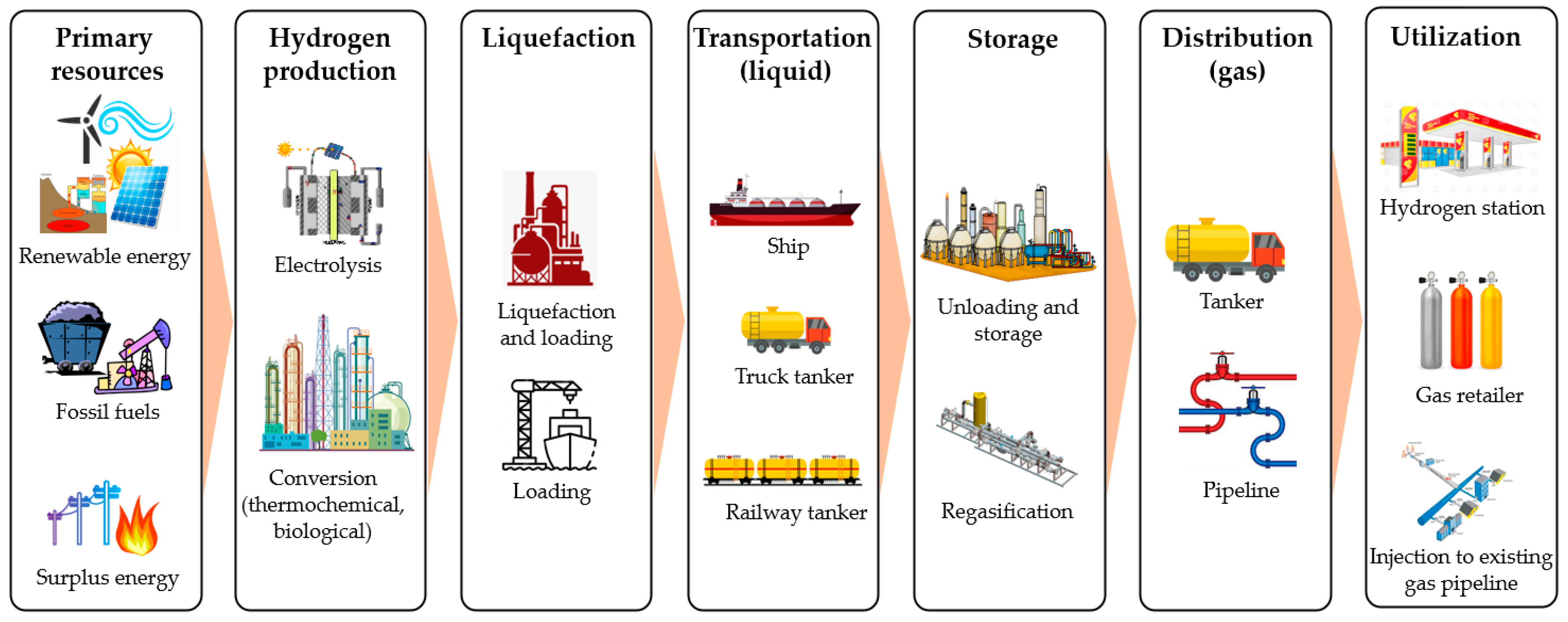
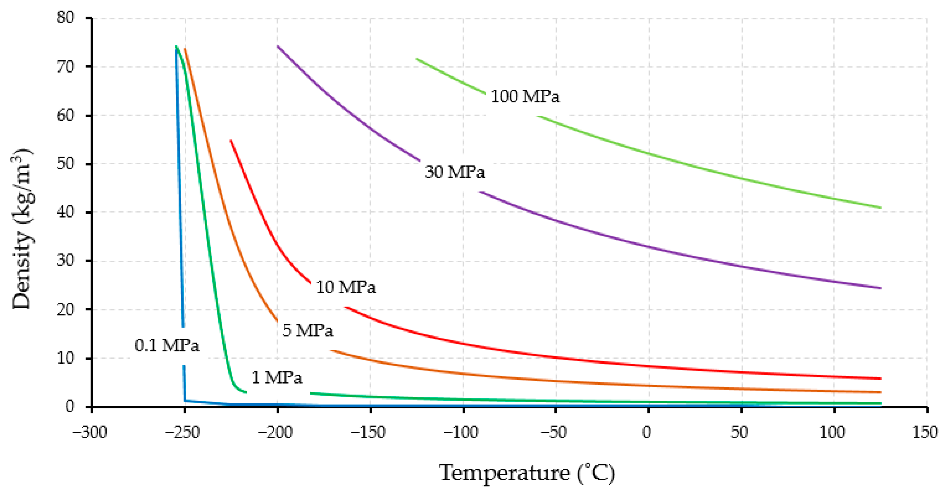
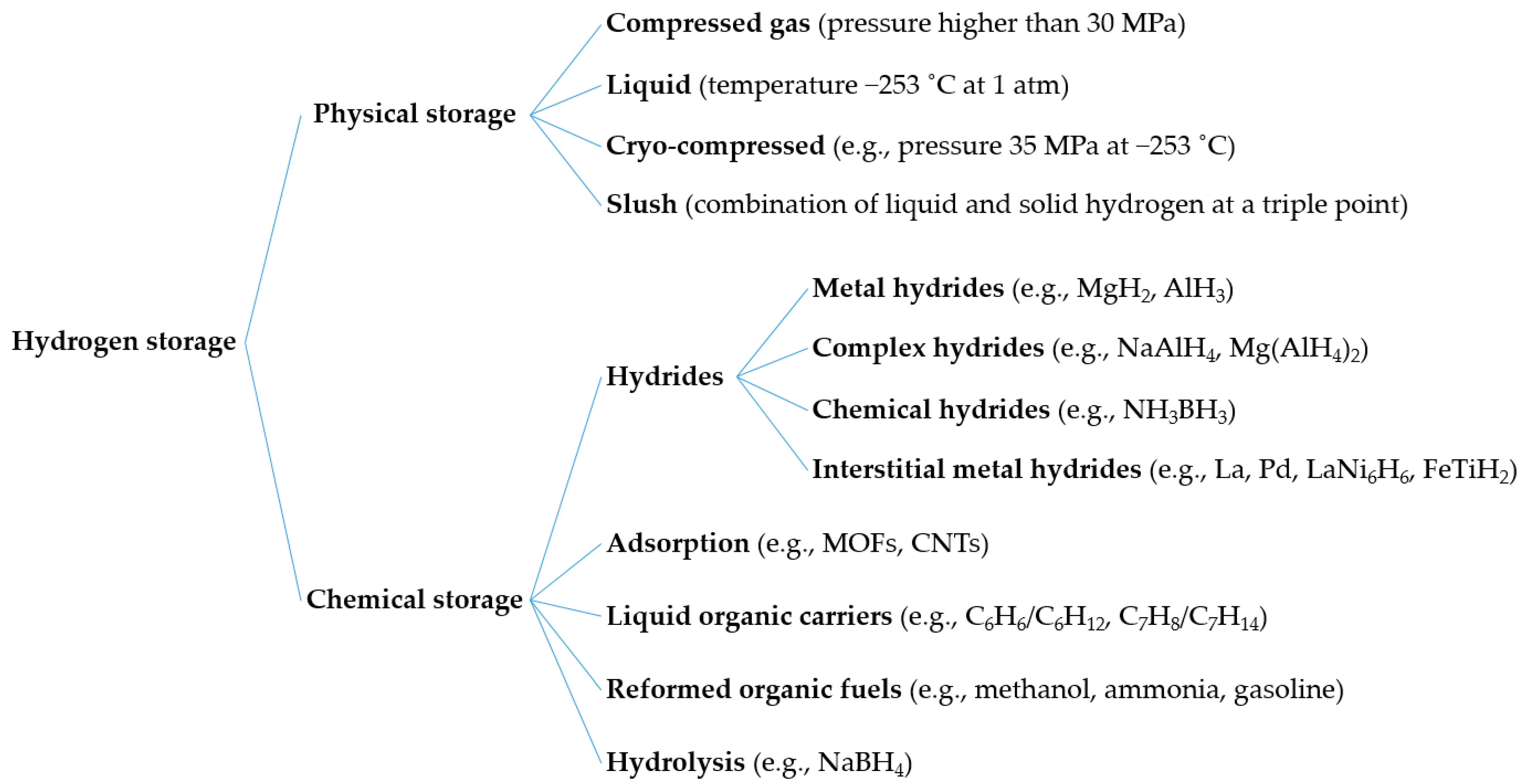
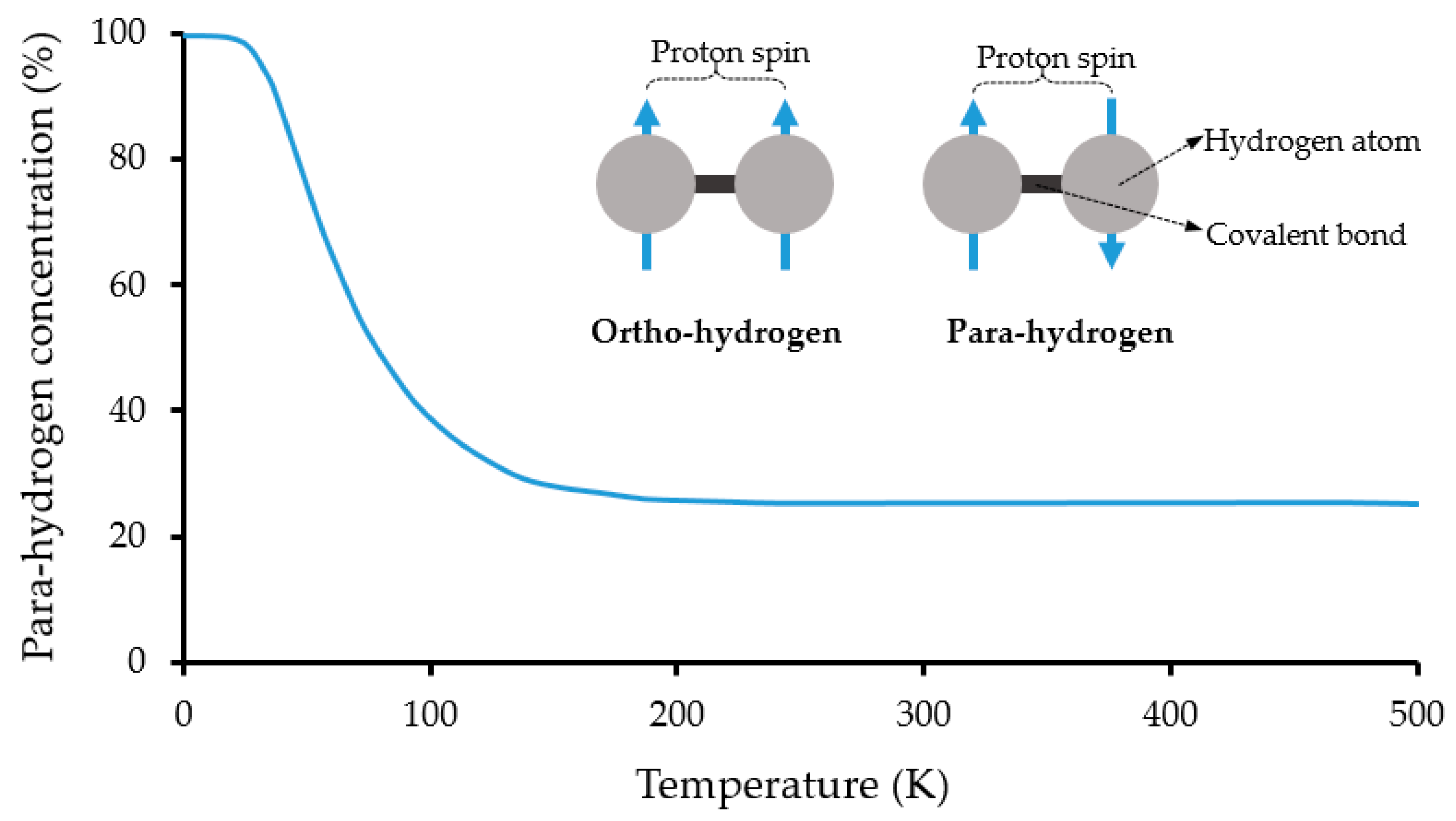
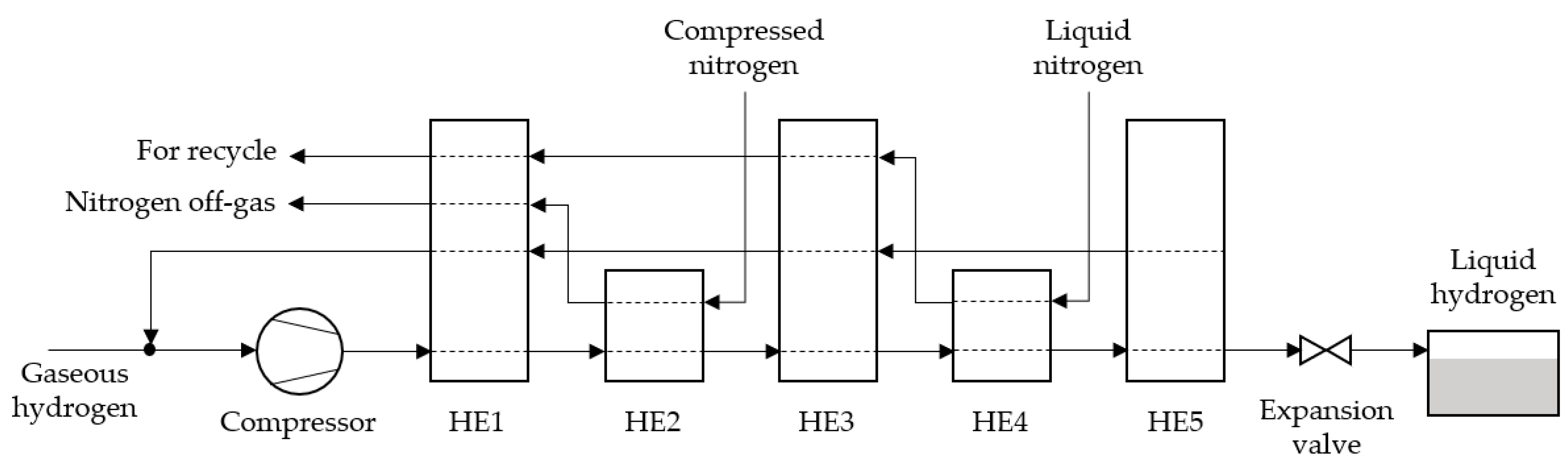
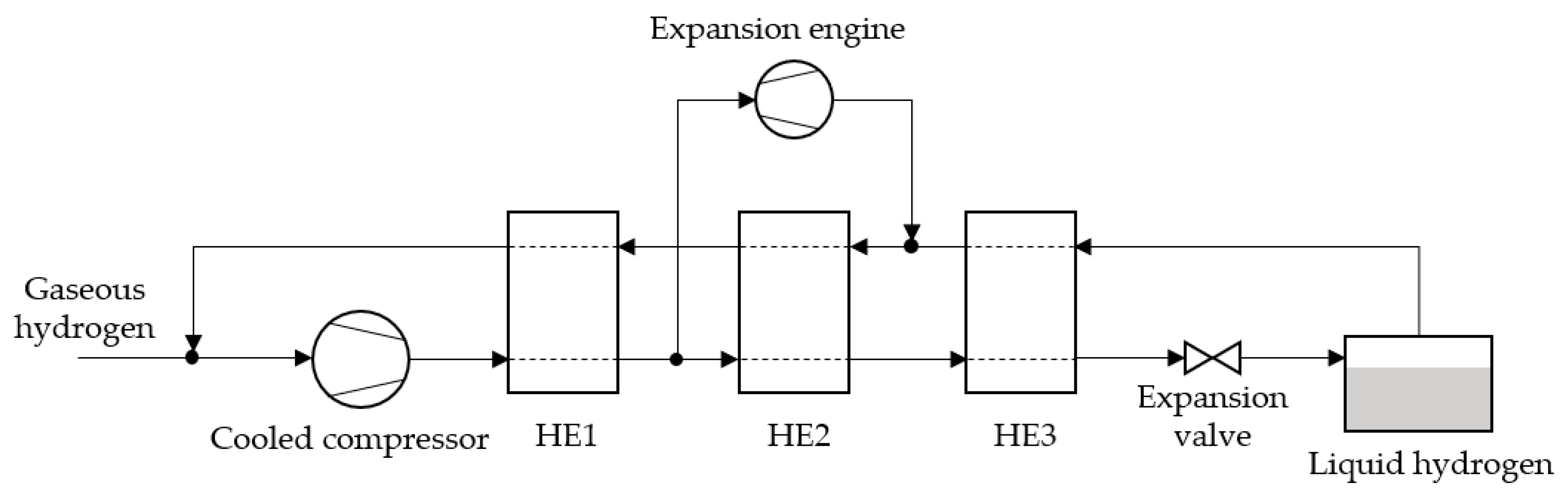
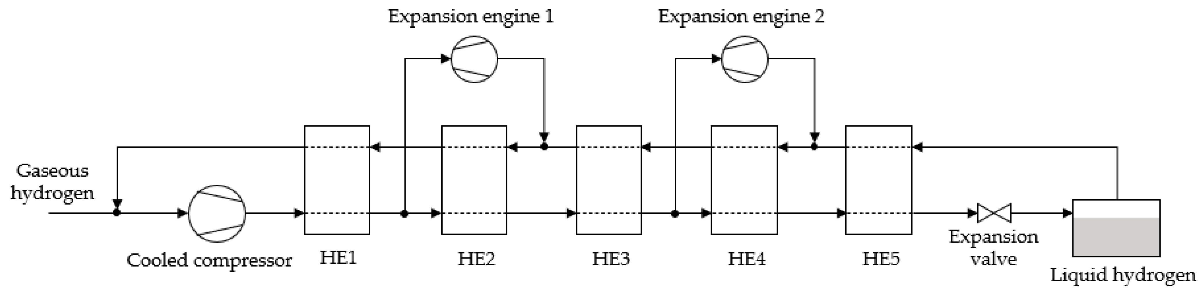
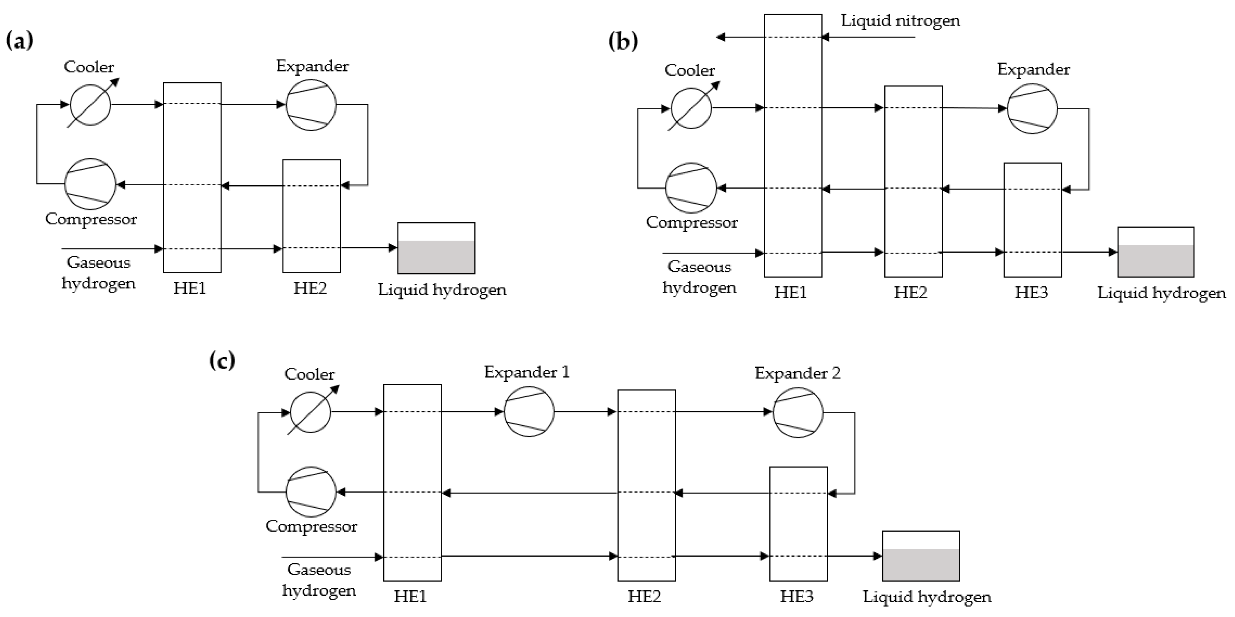
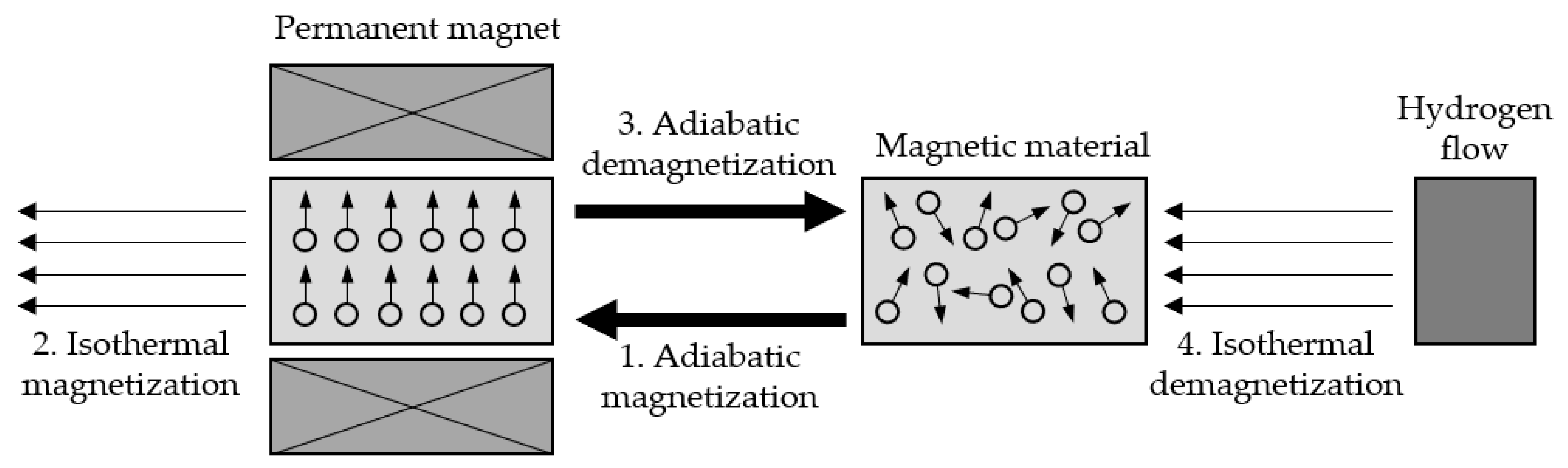
Table 1.
Physical properties of hydrogen.
| Properties | Value | Ref. |
|---|---|---|
| Molecular weight (g/mol) | 2.016 | [18,20] |
| Lower heating value (MJ/kg) | 118.8 | [18] |
| Higher heating value (MJ/kg) | 143 | [18] |
| Viscosity at 25 °C (cP) | 0.000892 | [20] |
| Boiling temperature at 1 atm (°C) | −253 | [18,20] |
| Melting temperature (°C) | −259 | [18,20] |
| Critical temperature (°C) | −240 | [20] |
| Critical pressure (MPa) | 1.3 | [20] |
| Density of gaseous hydrogen at 0 °C (kg/m3) | 0.08987 | [20] |
| Density of liquid hydrogen at −253 °C (kg/m3) | 70.85 | [20] |
| Density of solid hydrogen at −259 °C (kg/m3) | 858 | [20] |
| Critical density (kg/m3) | 31.2 | [20] |
| Heat capacity of gaseous hydrogen at 0 °C (kJ/kg·°C) | 14.3 | [20] |
| Heat capacity of liquid hydrogen at −256 °C (kJ/kg·°C) | 8.1 | [20] |
| Heat capacity of solid hydrogen at −259.8 °C (kJ/kg·°C) | 2.63 | [20] |
| Heat of vaporization at −253 °C (kJ/kg) | 447 | [20] |
| Heat of fusion at −259 °C (kJ/kg) | 58 | [20] |
| Thermal conductivity at 25 °C (W/cm·K) | 0.018 | [20] |
| Ionization energy (eV) | 13.5989 | [18] |
| Liquid-to-gas expansion ratio at atmospheric condition | 1:848 | [18] |
| Adiabatic flame temperature (°C) | 2107 | [18] |
| Research octane number (RON) | >130 | [18] |
| Thermal conductivity (20 °C, 1 atm) (W/m·K) | 0.1825 | [21] |
| Specific gravity of gas hydrogen at 20 °C and 1 atm | 0.0696 | [22] |
| Specific gravity of liquid hydrogen at −253 °C and 1 atm | 0.0710 | [22] |
| Latent heat of vaporization (kJ/kg) | 461 |
| Properties | Compressed Hydrogen | Metal Hydride (MgH2-10wt%Ni) | Liquid Organic (C7H8/C7H14) | Liquid Hydrogen | Liquid Ammonia |
|---|---|---|---|---|---|
| Density (kg/m3) | 39 (69 MPa, 25 °C) | 1,450 | 769 (1 atm, 20 °C) | 70.9 (1 atm, −253 °C) | 682 (1 atm, −33.33 °C) |
| Boiling point (°C) | −253 | - | 101 | −253 | −33.33 |
| Gravimetric hydrogen density (wt%) | 100 | 7.10 | 6.16 | 100 | 17.8 |
| Volumetric hydrogen density (kg-H2/m3) | 42.2 | 47.1 | 70.9 | 120.3 | |
| Hydrogen release temp. (°C) | - | 250 | 200–400 | −253 | 350–900 |
| Regeneration temp. (°C) | - | - | 100–200 | - | 400–600 |
| Enthalpy change to release hydrogen (kJ/mol-H2) | - | 118 | 67.5 | 0.899 | 30.6 |
Table 3.
Physical properties of liquid hydrogen.
| Properties | Value | Ref. |
|---|---|---|
| Density (kg/m3) | 70.85 | [20] |
| Volumetric energy density (kWh/L) | 2.36 | [55] |
| Gravimetric energy density (kWh/kg) | 33.3 | [55] |
| Heat of evaporation (kJ/kg) | 446 | [56] |
| Heat of ortho- to para- hydrogen (−253 #xB0;C) (kJ/kg) | 703 | [56] |
Table 4.
Characteristics comparison of ortho- and para-hydrogen [62].
Table 4.
Characteristics comparison of ortho- and para-hydrogen [62].
| Properties | Ortho-Hydrogen | Para-Hydrogen |
|---|---|---|
| Spin direction | Same direction | Opposite direction |
| Spin alignment | Parallel | Antiparallel |
| Energy state | Higher energy state | Lower energy state |
| Nuclear magnetic resonance (NMR) spectroscopy | Triplet | Singlet |
Table 5.
Comparison of combustion properties among fuels at atmospheric condition (temperature and pressure of 25 °C and 1 atm, respectively) [18,120].
| Properties | Hydrogen | Methane | Propane | Gasoline |
|---|---|---|---|---|
| Flammability limit (vol%) | 4.1–74.8 | 5.3–17.0 | 1.7–10.9 | 1.0–6.0 |
| Detonation limit (vol%) | 18.3–59.0 | 6.3–13.5 | 3.1–9.2 | 1.1–6.0 |
| Auto-ignition temp. (°C) | 585 | 540 | 490 | 246–280 |
| Min. ignition energy (mJ) | 0.017 | 0.274 | 0.24 | 0.24 |
| Stoichiometric mixture (vol%) | 29.6 | 9.5 | 4.0 | 1.9 |
| Laminar burning velocity (cm/s) | 270 | 37 | 47 | 30 |
Publisher’s Note: MDPI stays neutral with regard to jurisdictional claims in published maps and institutional affiliations. |
© 2021 by the author. Licensee MDPI, Basel, Switzerland. This article is an open access article distributed under the terms and conditions of the Creative Commons Attribution (CC BY) license (https://creativecommons.org/licenses/by/4.0/).
Share and Cite
MDPI and ACS Style
Aziz, M. Liquid Hydrogen: A Review on Liquefaction, Storage, Transportation, and Safety. Energies 2021, 14, 5917. https://doi.org/10.3390/en14185917
AMA Style
Aziz M. Liquid Hydrogen: A Review on Liquefaction, Storage, Transportation, and Safety. Energies. 2021; 14(18):5917. https://doi.org/10.3390/en14185917
Chicago/Turabian StyleAziz, Muhammad. 2021. "Liquid Hydrogen: A Review on Liquefaction, Storage, Transportation, and Safety" Energies 14, no. 18: 5917. https://doi.org/10.3390/en14185917
Note that from the first issue of 2016, this journal uses article numbers instead of page numbers. See further details here.