Article

Corrosion Behavior of VM12-SHC Steel in Contact with Solar Salt and Ternary Molten Salt in Accelerated Fluid Conditions

by
Gustavo García-Martin
*,
María I. Lasanta
,
María T. de Miguel
,
Andre Illana Sánchez
and
Francisco J. Pérez-Trujillo
Surface Engineering and Nanostructured Materials Research Group, Faculty of Chemical Sciences, Complutense University of Madrid, Complutense Avenue s/n, 28040 Madrid, Spain
*
Author to whom correspondence should be addressed.
Energies 2021, 14(18), 5903; https://doi.org/10.3390/en14185903
Submission received: 7 July 2021 / Revised: 3 September 2021 / Accepted: 13 September 2021 / Published: 17 September 2021

Abstract

:
Ternary low melting point mixtures with the addition of LiNO3 and Ca(NO3)2 have been presented as direct system candidates for CSP technologies due to having better physical and chemical properties than those of Solar Salt. In this study, thermal, physical and chemical properties are measured as is the corrosive behavior of stainless alloy VM12 (Cr 12%) when in contact with Solar Salt, 60% NaNO3-40% KNO3 (wt.%) and ternary 46% NaNO3-19% Ca(NO3)2-35% LiNO3 (wt.%). Gravimetric weight change measurements were performed on the test specimens, which were tested under accelerated fluid conditions (0.2 m s−1) at 500 °C for 2000 h. This research confirms the potential of this novel formulation as a thermal storage medium and validates the suitability of ferritic VM12-SHC stainless steel as a structural material for CSP technology with Solar Salt. Meanwhile, the results obtained by scanning electron microscopy and X-ray diffraction indicate a reduction in the protective character of the oxide layer formed on this alloy when the medium contains calcium and lithium components.

1. Introduction

Wealth and growth in society are associated with the capacity and independence of electricity generation, whereas conventional fossil fuel technology is a heavily polluting industry, mainly because it is an intensive producer of greenhouse gases (GHG) [1]; the depletion of natural resources also constitutes a reason to strengthen alternative renewable energy sources, such as concentrated solar power (CSP) plants.
CSP plant technology has a competitive status amongst other renewable sources, such as photovoltaic, hydraulic and wind energy, because it may be coupled with a thermal energy storage system (TES) that yields heat to the power block overnight or at peak demand. Between the two principal commercial CSP technology layouts, the central tower (CT) and the parabolic trough (PT), the latter is the more mature, fostering up-to-date production with higher electricity [2]. In commercial PT plants, the thermal oil used as a heat transfer fluid (HTF) releases heat to the thermal energy storage system (TES) with molten salt TES by means of a heat exchanger. Nevertheless, there is an inherent freezing risk of the nitrate mixture, which eventually clogs pipes and pumps due to the high melting point (~227 °C) of the current state-of-the-art Solar Salt (60% NaNO3-40% KNO3); therefore, researchers are concentrating on new fluids with better physical–chemical properties than those of Solar Salt and a higher working temperature range, lower melting point and higher decomposition temperature [3].
Ternary alkaline nitrate mixtures with Ca(NO3)2 and LiNO3 have a great potential to be used as an HTF and a heat storage medium (HSM). C.Y. Zhao et al. [4] designed several combinations, 50–80 wt.% KNO3, 0–25 wt.% LiNO3 and 10–45 wt.% Ca(NO3)2. The authors concluded that the melting points for the formulations 67.2% KNO3-19.3% Ca(NO3)2-13.5% LiNO3, 64.8% KNO3-24.8% Ca(NO3)2-1.4% LiNO3 and 63.7% KNO3-27.3% Ca(NO3)2-9.0% LiNO3 were 78 °C, 80 °C and 76 °C, respectively. However, thermodynamic simulation studies indicated that the eutectic point was 117 °C. Equally, Ca(NO3)2-NaNO3-LiNO3 is considered in CSP. Juntao et al. [5] determined a phase diagram with a eutectic point at 174 °C for the mole fraction combination 42.4% LiNO3-43.3% NaNO3-14.3% Ca(NO3)2, and the thermogravimetric analysis showed a 3% weight loss at 537 °C with a 10 °C/min heating rate. NaNO3-KNO3-LiNO3 ternary systems have also been studied [6].
The corrosiveness of molten salt is a huge problem in the CSP industry. The adequate use of LiNO3 implies a specific corrosion mechanism, regarding which some authors indicated a reduction in the corrosion as a result of its presence. The formation of LiFe5O8 and dense protective LiFeO2 layers is responsible for the steel corrosion resistance that would increase the service life of CSP [7]. The problem of LiNO3 is that it costs more than the current state of the art; it would increase LCOE with current technology [8]. Capital expenditure (CAPEX) in TES might be raised due to the replacement of the current state-of-the-art fluid by ternary or quaternary mixtures containing lithium at an amount between 13% and 23% because of the molten salt prices [9]. NaNO3 and Ca(NO3)2 are the cheapest commodities, around ~280 EUR/ton and ~254 EUR/ton, respectively. KNO3 is approximately three times more expensive than the previous components (~790 EUR/ton); meanwhile, LiNO3 is 6763 EUR/ton [10]. Thus, a balanced combination of low-cost constructive material and multicomponent formulations with less corrosive impact than “Solar Salt” might increase the efficiency of the CSP industry. Carbon steel and low chrome content [11] have been used with stainless steels in PT technology [12,13] for storage systems, pipes and exchangers. Compatibility studies of T22 steel (9% Cr-1% Mo) immersed in 20% LiNO3-52% KNO3-28% NaNO3, 30% LiNO3-10% Ca(NO3)2-60% KNO3 and 10% LiNO3-10% Ca(NO3)2-60% KNO3-20% NaNO3for 1000 h in static conditions show lower corrosion rates than those of the specimens in Solar Salt [14]. There are investigations assessing the corrosion resistance of steels in Solar Salt and other nitrate formulations [15,16,17]. Almost all corrosion studies have been performed in static conditions where, at such extreme operational conditions, Cr content is essential to form protective layers, i.e., Cr2O3 [13,18]. Aiming at reducing the cost of energy, alternative ferritic/martensitic materials, such as P92 (wt.%: 8.8Cr-0.5Mo-1.8W) [19], or the new generation of ferritic steel, such as VM12-SHC (super high corrosion resistance) [20] have been used. The latter material is suitable for different energy technologies; its specific chemical composition (wt.%: 12Cr-1.6Co-1.5W) provides a special performance in terms of creep resistance and steam corrosion up to 620 °C according to the manufacturer, Vallourec. There are many computational studies predicting corrosion issues thermodynamically and kinetically in advance [21,22,23]. However, experimental research is mandatory because of the complexity in the case of molten salt. At the moment, there are very few studies of VM12-SHC in contact with molten salts exhibiting good endurance. For instance, P. Audigié et al. [24] conducted one of the first investigations of this material under a static immersion in 60% NaNO3-40% KNO3 for 1000 h. D. Fähsing et al. [25] compared the corrosion resistance between VM12 and another ferritic/martensitic steel with a lower chrome content in pure Solar Salt and a different impurity level (300 ppm of Cl and SO4−2). VM12 experienced less mass gain after 1000 h at 560 °C in all cases, with an internal protective chromium layer. VM12 could be among the potential constructive materials that can be used in CSP and has been considered for the replacement of T91 [26]. Its mechanical properties and reasonable costs make this material suitable for coating treatment. To date, its positive corrosion inputs stem from investigations performed in static conditions in the binary. Therefore, in this study, corrosion resistance tests were performed on specimens of VM12 in an accelerated regime of Solar Salt and a ternary molten salt mixture, 19 wt.% Ca(NO3)2-46 wt.% NaNO3-35 wt.% LiNO3. The latter was selected due to its suitable thermo-chemical properties and, also, because of the use of two economical nitrates, which may partially compensate for the negative economic impact of LiNO3. The substantial amount of LiNO3 was also an important reason for its selection, as it enables the study of the corrosion behavior competition between oxidation and “lithiumization”.

2. Materials and Methods

2.1. Materials

2.1.1. Preparation of the Salt Mixtures

The required primary components of NaNO3 KNO3, LiNO3 and Ca(NO3)2·4H2O (QuimipurTM) were measured in weight percentage in a precision balance (Mettler Toledo mod. AE/100). The two mixtures assessed were “Solar Salt” with a weight percentage of 60 wt.% NaNO3-40 wt.% KNO3 and ternary molten salt, 19 wt.% Ca(NO3)2-46 wt.% NaNO3-35 wt.% LiNO3.
The composition of the nitrates is detailed in Table 1. The impurity levels of chlorides and sulphates were Na(SO4)2 of up to 500 ppm and 250 ppm in the formulations, respectively. These impurities are also involved in molten salt container degradation and the physical–chemical property change [27].

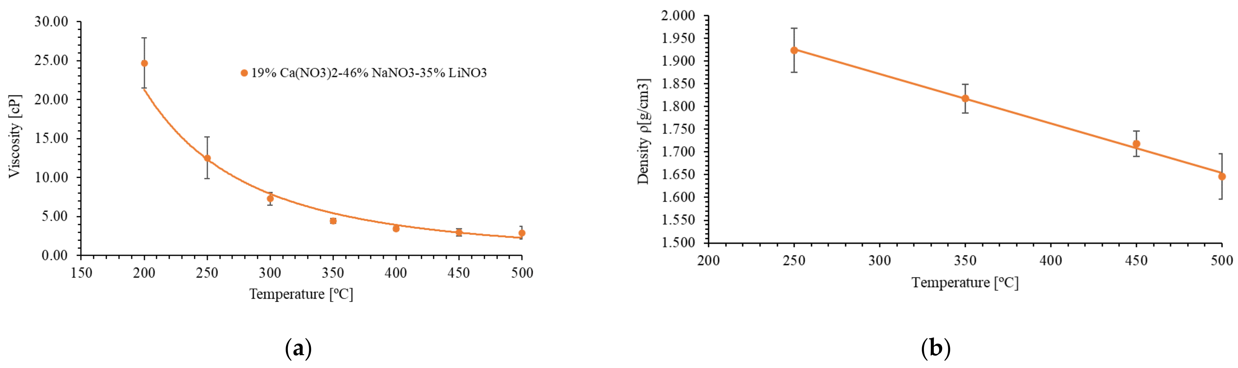
2.1.2. Measurement of Physical–Chemical Properties

In this investigation, thermodynamic properties were measured, including the melting and degradation points, specific heat, density and viscosity of the molten salts.
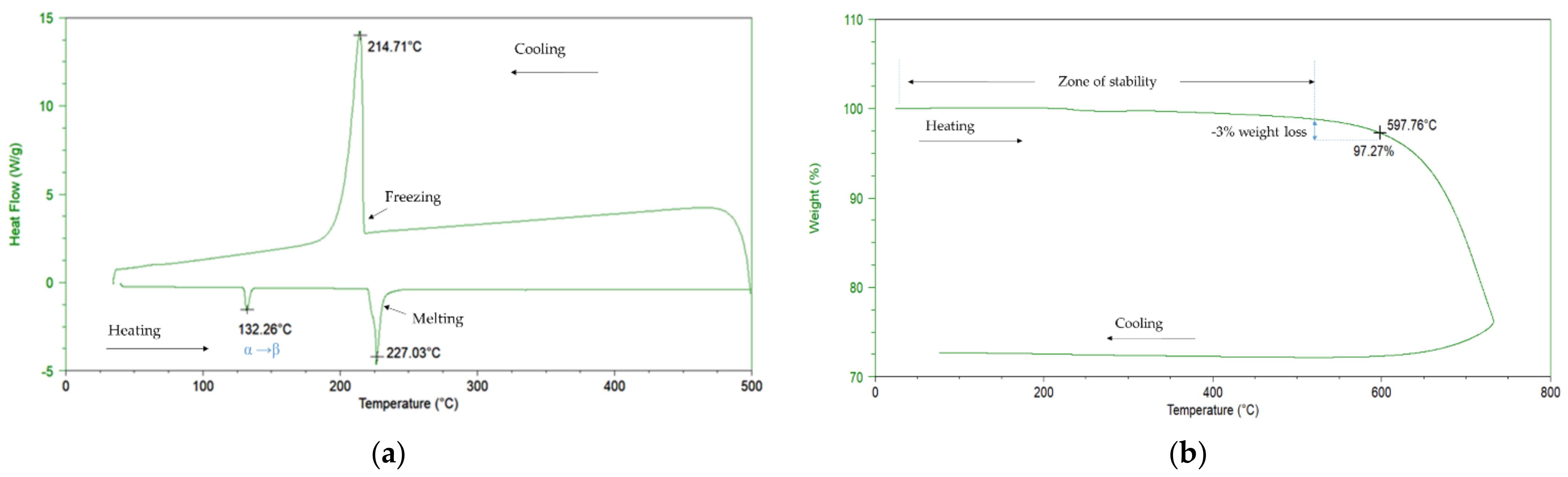
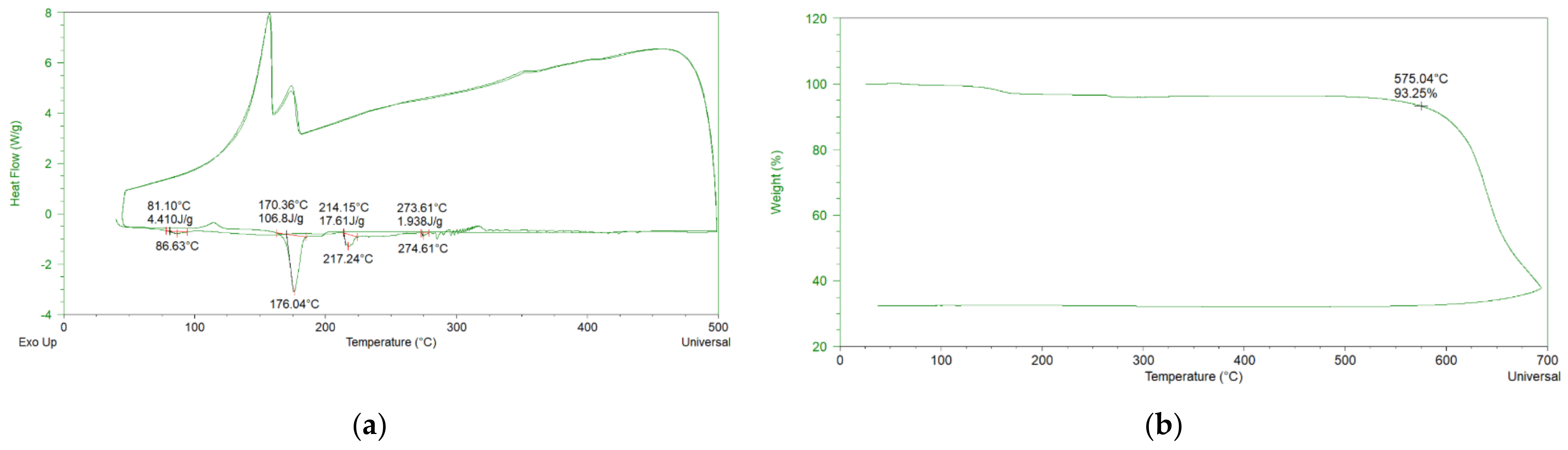
  • Melting point and thermal decomposition
Differential scanning calorimetry (DSC) is the most widely used technique for the melting point determination of molten salts. [8,28,29]. The melting point was measured using a TA Instruments DSC mod. Q20 coupled with a cooling system, which allows a working temperature range between −90 °C and 550 °C and a temperature precision of ±0.1 °C. Hermetic aluminum pans were employed on the sample holder in the cell. The analysis was conducted in an inert atmosphere (N2), from room temperature up to 500 °C and a heating rate of 10 °C/min, which is the optimum testing velocity to identify phase transitions and melting points [30].
For the thermal degradation study, Q600 TA instrument thermogravimetric analysis (TGA) equipment was used. Its horizontal balance, with a 200 mg capacity and 0.1 μg sensitivity, was placed in a furnace with a maximum working temperature of 1500 °C and programmable heating rates of between 0.1 °C/min and 25 °C/min. Both the heating rate and the atmosphere parameters affect the degradation temperature evaluation [31]. Commonly, a 10 °C/min heating rate and N2 or Ar inert atmospheres are used [32,33]. In these experiments, the TGA of the specimens was performed in a platinum crucible from room temperature up to 800 °C under a flowing N2 atmosphere of 100 mL·m−1. Prior to the analyses, both instruments were calibrated with indium.
  • Specific Heat capacity measurement
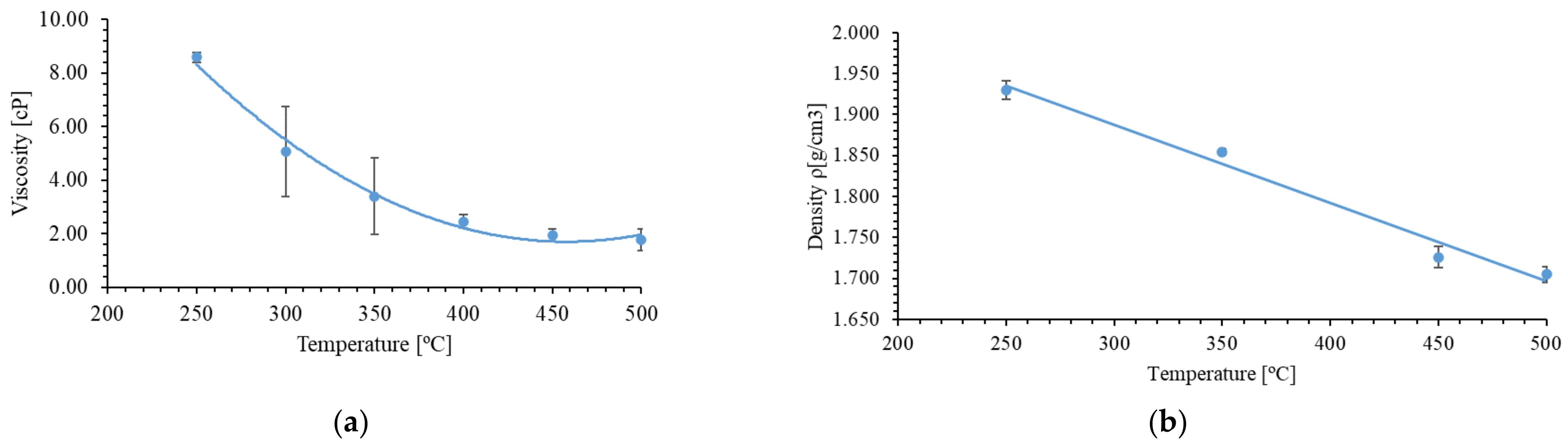
The TA Instruments DSC mod. Q20 was used to measure the specific heat capacity (Cp) by its modulated differential scanning calorimetry (MDSC) feature. The standard MDSC was conducted according to the ASTM standard E1269; it was also implemented by other researchers [34]. To ensure the reproducibility of the measuring setup because of the facility sensitivity, several experiments under similar conditions were conducted for each salt: “Solar Salt” and 46% NaNO3-19% Ca(NO3)2-35% LiNO3. The sample masses (around 3 mg) of molten salts were adequately deposited, covering the bottom of the aluminum pan in every experiment.
  • Density measurement
Density (ρ) (g/cm3), is an important parameter to evaluate the mass flow in pipes and the volumetric capacity of tanks [35]. It is certainly a challenging lab measurement procedure at a high temperature (i.e., 500 °C) due to the lack of commercial apparatuses limited up to ~300 °C [36]. Therefore, experimentally, this property is less reported in the literature [36]. Most of the apparatuses are based on the Archimedes principle [37,38], while others have been determined by the pycnometer concept [39]. Using this insight, an empty graduated borosilicate glass tube was duly weighted in a calibrated Radwag precision balance, mod. PS-3500 R2. Around 12 mg of powder salt was placed in the tube. Once fused in a verified furnace and stabilized for five hours, the liquid content was weighted, and the occupied volume was recorded. Density was determined at 250 °C, 350 °C, 450 °C and 500 °C, by repeating the measurements five times at each temperature. Then, by means of the relation between the recorded mass (m) and its volume (V), the material density (ρ) was obtained.
  • Viscosity measurement
Viscosity µ (cP) is an important factor to take into account in order to minimize the energy consumption of the impeller pumps in CSP plants [40,41]. In this investigation, the dynamic absolute viscosity (µ) was measured, which consisted of an evaluation of the particles’ internal resistance against shear stress (σ, (Pa)). This relates viscosity and the share rate (γ, (1/s)) by the following equation [42]:
σ = µ…γ
The behavior of the molten salts studied was examined by a TA instrument, mod. Discovery Hybrid Rheometer (DHR1), with an adjustable parallel plate fitting. The whole system was placed in a high temperature furnace capable of reaching 700 °C. In this study, viscosities were evaluated from 200 °C to 500 °C with every increase in 50 °C temperature and a shear rate variation from 10 to 1000 (1/s). Before the measurements, the equipment was calibrated with a reference polymer specimen.

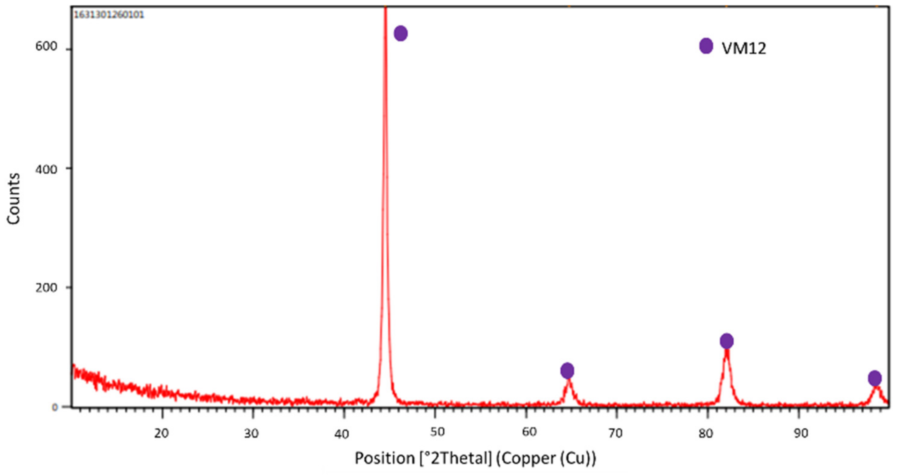
2.1.3. Corrosion Study of the Substrates

Corrosion studies were performed at an isothermal temperature of 500 °C and accelerated fluid conditions in a pilot plant. The velocity of the test was set to 0.2 m·s−1. This velocity was selected on the basis of the flow velocity, which is given in areas near to pipe bends and valves in the current CSP plants (0.2–0.5 m·s−1), which are areas where high levels of corrosion are found. This patented (ES2534850-B2) pilot plant, built in AISI 321 steel, enables one to simulate a medium flowing under real operational conditions. A place area with an alumina sample holder allows one to place specimens, with 20 × 10 mm size, parallel to the molten salt flow for degradation tests of materials. This facility was explained in detail in a previous work [16]; it was used to compare static conditions versus accelerated flow conditions. It is feasible equipment for simulating corrosion effects when salt circulates through steel tubes in a CSP plant.
VM12-SHC steel was the substrate selected for corrosion evaluation. The chemical composition of the material was characterized as received by SEM-EDX in a weight percent of 0.38% Si, 0.25% V, 12% Cr, 0.42% Mn, 1.78% Co, 0.36% Ni, 0.39% Mo and 1.42% W and Fe in balance. These values are in line with those reported by the manufacturer [20]. Moreover, an XRD was performed on the material before the test (see Figure 1).
In this investigation, the accelerated flow effects were monitored at 48 h, 75 h, 175 h, 250 h, 500 h, 750 h, 1000 h, 1500 h, 1750 h and 2000 h (h). For this purpose, three samples were prepared for each measurement time. Specimens were superficially grounded with P180 sandpaper and cleaned in distilled water followed by 5 min of sonication in ethanol before testing.
Once the samples were removed from the pilot plant, they were cooled slowly in warm distilled water to eliminate the remaining solidified salt with which they had been in contact. They were then dried and weighed, and an average was taken from five values of their weights. Thus, the formula used to calculate the mass variation over time was
Δm/S0 = (mfmi)/S0
where mi is the initial mass of the specimen, mf is the mass of the sample at the selected time, and S0 is the initial area of the specimen.

3. Results and Discussion

3.1. Characterization of the Salt Mixture

Table 2 presents all the results obtained for the main physical–chemical properties of both mixtures studied.
The DSC revealed a melting point of the Solar Salt at 227 °C, along with its characteristic endothermic phase solid–solid transition (α, β) of the KNO3 at around 132 °C [43]. This signal also appears in higher compositional formulations and can be shifted at a different heating rate [38]. The exothermic curve with a maximum peak at 214 °C was produced in the cooling segment slope and delayed with respect to the melting point because of atom nucleation [44] (see Figure 2a). The decomposition temperature was 597 °C. This corresponds to a mass loss of 3% with respect to the stability slope (see Figure 2b).
Generally, authors assign a working temperature range of 240 °C–565 °C [45]. The average specific heat capacity at 500 °C was 1.55 J/g °C (see Figure 3), in line with other investigations [46].
Regarding the viscosity, the average value at 300 °C was 5.06 cP, which is higher than the 3.26 cP reported by González-Roubaud [47]. Most of the researchers stated Arrhenius or polynomic equation types with a temperature dependence of the viscosity. In this case, the relation one fits better with the polynomic mathematic expression, µ = 0.002·T2 − 0. 140·T + 33.805 (see Figure 4a).
The average value obtained for density for the range between 250 °C and 500 °C was 1.804 g/cm3 (see Figure 4b). Antoni Gil et al. [48] determined a similar average of 1.870 g/cm3 between 265 °C and 565 °C.
In comparison with “Solar Salt”, the studied ternary mixture, 19% Ca(NO3)2-46% NaNO3-35% LiNO3, melted at 176.04 °C and was stable up to 575 °C (see Figure 5). There were two endothermic peaks at 86.63 °C and 217 °C due to water loss from Ca(NO3)2.4H2O during the first thermal cycle; the second moisture release required a higher amount of energy (17.01 J/g) [49]. When calcium content is reduced, mixtures tend to have higher stability as observed by Judith C. et al. [44] for ternary Ca-Na-K nitrate combinations. Moreover, the thermal stability enhancement is a consequence of lithium oxides, Li2O and Li2O2, as reported by T. Wang et al. [50]. Thus, this investigated ternary mixture increases thermal range with respect to Solar Salt due to LiNO3 presence.
The viscosity values at 500 °C were 2.93 cP. Meanwhile, Solar Salt resulted in 1.12 cP, with an equation tendency, µ = 8.64·106·T−2.437, for the curve represented at different temperatures (see Figure 6a). LiNO3 presence enables one to reduce viscosity and raise Cp as evaluated by Coscia, Kevin et al. [51]. In this work, the ternary mixture 19% Ca(NO3)2-46% NaNO3-35% LiNO3 presented a specific heat capacity of 1623 J/g·°C at 500 °C, higher than that of Solar Salt (see Figure 3). This is similar to the average value collected by Zhang Pheng et al. [32] for the formulation 30% LiNO3-18% NaNO3-52% KNO3 up to 380 °C; when formulation varied to 20% LiNO3-28% NaNO3-52% KNO3, the heat capacity suffered a significant reduction value, 1.091 kJ/kg·K at 390 °C [52].
The density evaluations resulted in a linear decrease with temperature according to the expression ρ = 2.1968 − 0.0011·T, and a lower density than that of Solar Salt was presented in all temperature ranges caused by the large amount of LiNO3 (see Figure 6b).
The energetic density (ƍε) calculations for the ternary mixture and the reference “Solar Salt” were taken from the experimental measurement, being expressed as follows: ƍε = ρ·Cp·ΔT [52], where ρ is the density, Cp is the specific heat capacity, and ΔT is the working temperature range. The binary mixture presented 721 MJ/m3 at 500 °C, similarly to the data reported by Wang et al. [53] for the same temperature, 756 MJ/m3. The investigated ternary combination of nitrates of this research, Li-Ca-Na, with 35 wt.% LiNO3 resulted in 867 MJ/m3, which is an outstanding value when compared with that of other authors. For instance, Parrado et al. [9] gathered known mixtures and new formulations, 60% NaNO3-40% KNO3 (550 MJ/m3), 48% Ca(NO3)2-7% NaNO3-45% KNO3 (539 MJ/m3), 20% LiNO3-52% KNO3-28% NaNO3 (513 MJ/m3), 30% LiNO3-10% Ca(NO3)2-60% KNO3 (607 MJ/m3) and 10% LiNO3-10% Ca(NO3)2-60% KNO3-20% NaNO3 (680 MJ/m3).
So, the studied ternary mixture presented higher storage capacity for a parabolic trough system, although its drawback is the resistance to flow. Besides, its corrosive impact must be evaluated in different materials.

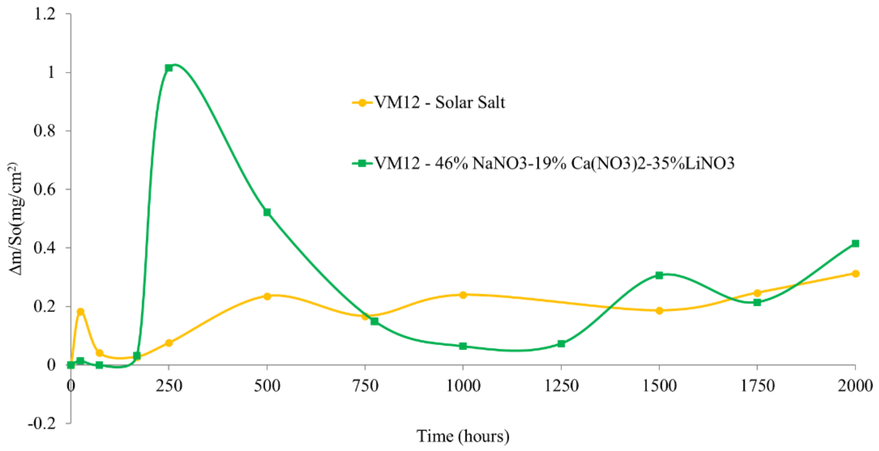
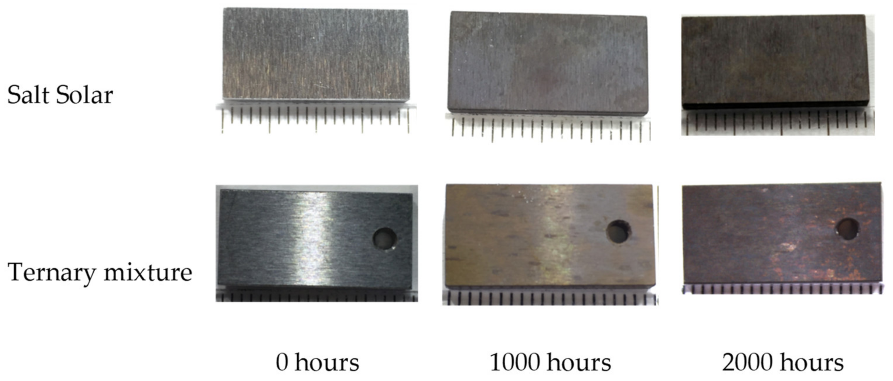
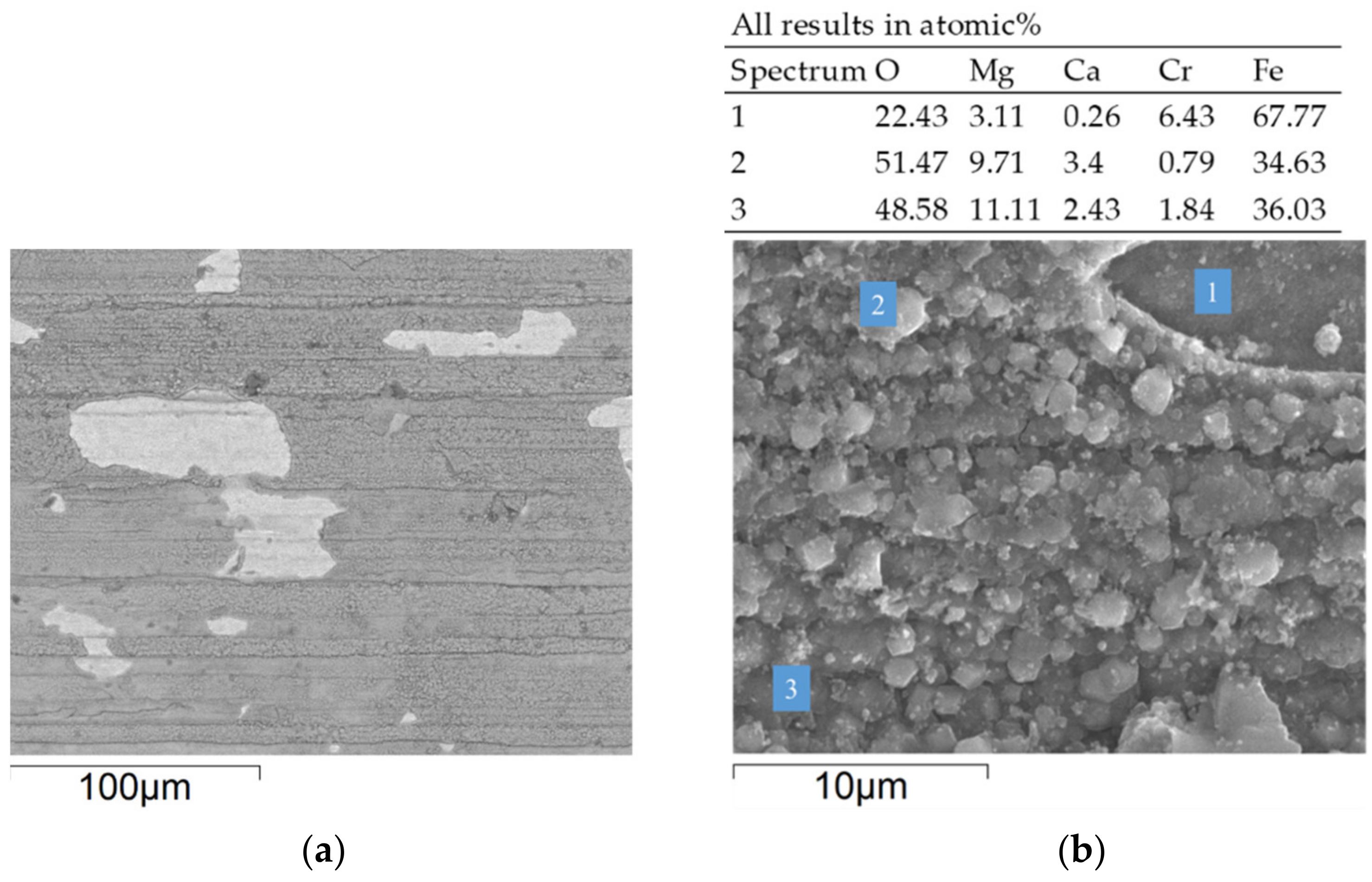
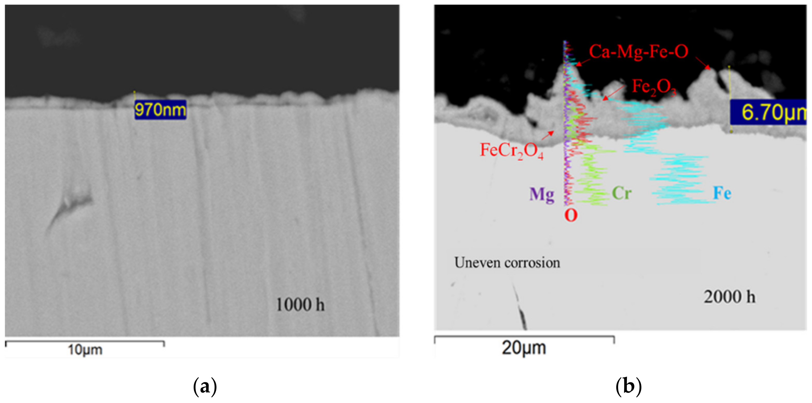
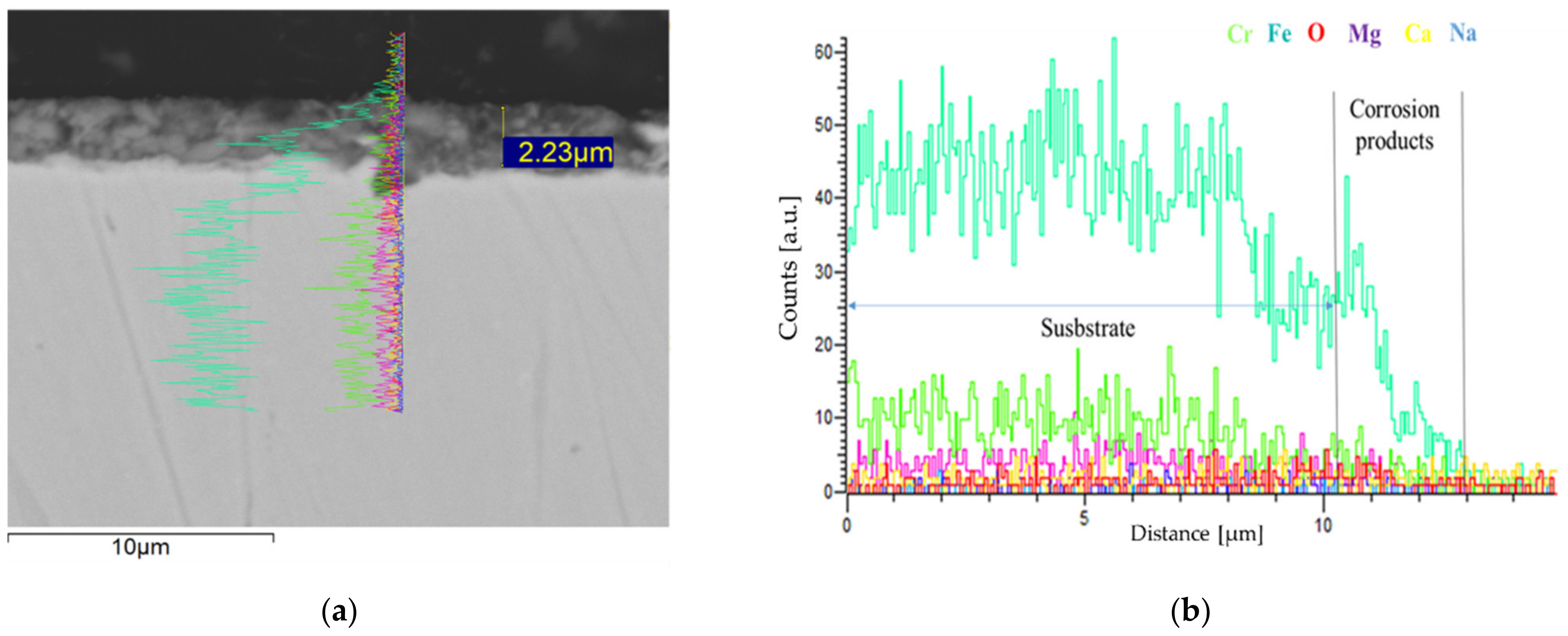
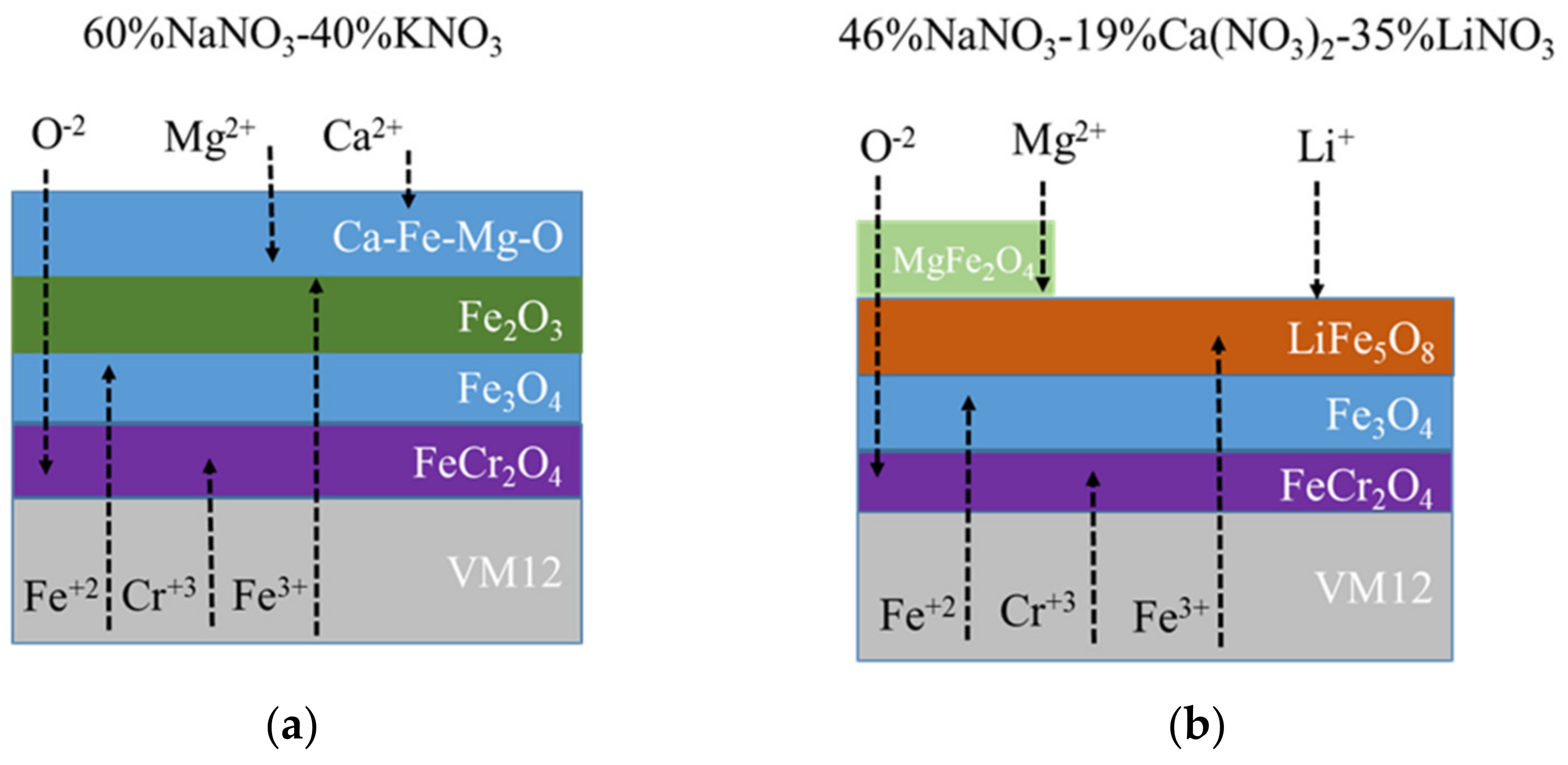
3.2. Corrosion Behavior in VM12

Figure 7 shows the gravimetric results of the VM12 in Solar Salt and the new ternary mixture formulated at 500 °C with a molten salt flow rate of 0.2 m/s. There was barely any weight loss when in contact with 60% NaNO3-40% KNO3. A sinusoidal shape was observed during the test when in contact with 46% NaNO3-19% Ca(NO3)2-35% LiNO3, with a gained weight mass of 0.5 mg/cm2 after 2000 h.
The weight variations correlated with a noticeable spallation in different areas of the sample as may be seen in a visual inspection of the coupons (see Figure 8).
However, any evident degradation signal was identified visually with the current state-of-the-art fluid. In Solar Salt, after 2000 h, there were preferential oxide growth areas on the sample, surely caused by grinding defects and the flow direction (see Figure 9). In the same figure, The SEM-EDX measurements on the surface revealed an atomic percentage of Fe, Cr and O, an indication of Fe-Cr-O spinels. Meanwhile, according to the specific chemical analyses #1 and #2 of the sample, a preferential combination of Fe-O was formed. Although very poor, Na presence leads one to think of a possible intermediate Na2O formation due to the oxyanion (O−2) affinity with this element [54].
The identified magnesium atomic percentages, #1:2.42 and #2:2.27 (see Figure 9), come from salt impurities, Mg(NO3)2, forming unprotected complex oxides from a reaction with the outer Fe2O3 (see Equation (3)). Besides, some researchers credited magnesium reactivity with a direct responsibility for NOx emissions during the plant commissioning [8].
MgO + Fe2O3 + MgFe2O4 ↔ MgFe2O3
Regarding the ternary mixture developed, although Ca(NO3)2 is one of the main components of the designed ternary mixture and molten salt impurities, the SEM-EDX atomic spectrum analysis (see Figure 10b) revealed a low presence of Ca specimens. That also means a low carbonate existence due to the large LiNO3 amount and its greater activity.
Severe delamination occurred (see Figure 10a), and a loss of corrosion products could be observed in the images of the surfaces (light color areas); this was confirmed by the increasing amount of Cr and Fe with lower O (22.43%) incidence after the SEM-EDX #1 chemical element analysis spectrum (see Figure 10b). The fluid movement provoked a pulling force that encouraged the mechanical separation of the corrosion products from the substrate.
When the material transversal section was compared after its exposure to the different molten salts, it was observed that the SEM cross-section of VM12 showed a low corrosion product generation with a 970 nm layer after being in contact with Solar Salt for 1000 h. General corrosion persisted; at the end of the experiment, however, there were uneven corrosion layers with a maximum thickness of 6.7 µm (see Figure 11a,b).
The line scan analysis indicated a majority presence of Fe, Cr and O, as well as Mg to a lesser extent. These findings are in line with the posterior structural phases identified in X-ray diffraction. The outer corrosion product scales (see Figure 11b) are promoted and formed by the impurities in molten salts at a high temperature [55].
When compared with the sample cross-section after 2000 h of exposure to 19% Ca (NO3)2-46% NaNO3-35% LiNO3, VM12 showed a layer thickness of 2.23 µm ( see Figure 12a) with a compact zone close to the interface lengthwise). In the SEM-EDX linear spectrum of the oxide layer (see Figure 12b), it can be correlated with the intensity change of the Cr signal, of which Fe and O together had the higher counts. Moreover, weak Mg and Ca signals were observed, which are correlated to the SEM-EDX results on the surface of the sample at the end of the test (see Figure 10b).
Figure 13a shows the XRD analysis of VM12 after “Solar Salt” exposure, It reveled that the crystalline complex CaFe16Mg2O27 was the option that best suited their intensity and position peaks. This crystalline phase evidenced the interaction between hematite and Mg+2 and Ca+2 (see Figure 11b). It is worth mentioning only crystalline species can be detected, which means that existing species with amorphous structures are not identified by XRD.
On the other hand, the XRD analysis of the material in contact with the ternary mixture (see Figure 13b) confirmed a corrosion multi-layer mainly composed of LiFe5O8, hematite, magnetite and FeCr2O4. Although NaNO3 accounted for 46% of the total ternary mixture weight, any crystalline structure could be identified with Na. Their activity was probably slowed down because of the greater Li+ activity. This is a positive phenomenon against impurity concentration enhancement, such as NaCl or Na2SO4 [56]. The XRD diffractogram also corroborated that lithium reacted with Fe2O3 to generate LiFe5O8 (see Equation (4)), as well as the unprotected MgFe2O4 oxide, which justifies the spallation observed.
6Fe2O3 + 2Li+ → 2LiFe5O8 +2Fe3+ + 2O2−
There were barely any remarkable phase intensity peaks related to crystalline hematite, but magnetite signals may be allocated more precisely. Thus, there was a rapid consumption of the generated Fe2O3 that reacted with the lithium oxide. This phenomenon was also observed by Wei-Jen Cheng et al. [7] in a similar chromium content alloy X20 (12 wt.% Cr) in the presence of a ternary nitrate mixture of Li, Na and K in static conditions; at the same time, outer corrosion scales corresponded to lithium oxide layers and the inner one to protective chromium spinel.
Furthermore, the protective specimen LiFeO2 might be formed by depletion of the LiFe5O8 that grew on the substrate [7]. This also could occur by a direct reaction between magnetite and lithium oxide Li2O:
LiFe5O8 + 3Li+ → 4LiFeO2 + Fe3+
Fe+3 + Li+ +2O2− → LiFeO2
Despite these reaction types, the two above-mentioned mechanisms were not preferential with VM12 and this ternary fluid in the accelerated conditions, and the protective oxide was not identified in XRD.
Figure 14a,b shows the corrosion mechanism proposed for the ternary mixture and “Solar Salt” as a result of this study. In short, there have been studies on neither ternary molten salt mixtures nor accelerated conditions in VM12 to date; nevertheless, the first investigation of VM12 immersed in 60% NaNO3-40% KNO3 resulted in a good corrosion resistance, with a weight gained of ≈1 mg/cm2 after 1000 h of tests in static conditions [57], which is higher than the mass obtained in this research, 0.3 mg/cm2. This difference can be explained by the fact that the working temperature was 580 °C. D. Fähsing et al. [25] investigated this material under Solar Salt at 560 °C and with an addition of 300 ppm Cl and SO4−2 impurities, the latter in the same range used in this research. The material had 0.07 mg/cm2 after 2000 h, and a protective oxide chromium scale in the inner part of the multi-layer and corrosion products that is consistent with those obtained in this investigation was detected. Nevertheless, the higher mass gained could be attributed to the effect of fluid circulation in this research. VM12 tended to form protective layers very quickly during the first test hours in contact with the accelerated ternary mixture. As a consequence of their insufficient compactness and stability, it suffered scale spallation from 500 h of running. In contrast, the substrate in contact with Solar Salt generated a more stable multilayer oxide scale.

4. Conclusions

This work assessed the physical–chemical properties of a ternary mixture containing 46% NaNO3-19% Ca(NO3)2-35% LiNO3, the corrosiveness effect in the ferritic alloy VM12 and its comparison with the current state-of-the-art fluid. Corrosion tests were evaluated in a patented pilot plant with a fluid movement of 0.2 m/s during 2000 h of exposure at 500 °C.
The ternary mixture resulted in a melting point of 176 °C and 575 °C degradation, which would make it possible to increase the thermal working range in a direct thermal energy storage system, and a Cp of 1.6 J/g°C gave it higher energy density (MJ/m3) than that of Solar Salt. In contrast, viscosity values were above those obtained for Solar Salt at up to 400 °C because of Ca(NO3)2. This would imply more energy consumption from pump impulsion that, together with lithium price, aggravates the levelized cost of energy.
The compatibility studies between the material and fluids were performed with the same chloride and sulphate impurity levels. The corrosion results of the newly formulated fluid in VM12 (12% Cr) demonstrated a particular oxidation corrosion mechanism due to the presence of LiNO3, with a superior mass gained of the coupons to that of Solar Salt at the end of the test due to lithium basicity. The formation of compact layers of lithium oxide was not promoted, thus explaining the less protective crystalline structure identification of LiFe5O8 in XRD rather than the upper protective scale LiFeO2. The lack of lithium protective oxides along with the complex oxides formed with impurities (MgFe2O4) on the surface of the ferritic material yielded severe scale spallation in contact with the ternary mixture. Thus, according to the gravimetric, microstructural characterization and phase analysis of the corrosion products, it can be stated that what prevailed was the preference for the protective chromium oxide formation in the oxidation mechanism.
VM12 shows better compatibility with Solar Salt than with the ternary mixture in an accelerated fluid regime. The mass gained value in accelerated flow conditions harmonized with the data previously obtained by other authors for static conditions and corrosion products that were mainly Fe2O3, F3O4 and FeCr2O4.
In view of these results, the ternary mixture did not turn out to be a clear alternative to replace Solar Salt as a heat transfer fluid and/or thermal storage system. It is necessary to study their environmental and cost impact. The suitability of VM12 in Solar Salt was demonstrated in accelerated fluid conditions for 2000 h at 500 °C. However, this material did not present good resistance in the ternary nitrate mixture of Ca-Na-Li.

Author Contributions

Conceptualization, F.J.P.-T. and G.G.-M.; methodology, G.G.-M.; investigation, G.G.-M. and M.I.L.; writing—original draft preparation, G.G.-M.; writing—review and editing, G.G.-M. and M.T.d.M.; visualization, A.I.S.; supervision, F.J.P.-T.; funding acquisition, F.J.P.-T. All authors have read and agreed to the published version of the manuscript.

Funding

This investigation has been funding from the Ministry of Science and Innovation of Spain under grant agreement No PCI2020-120703-2 (EuroPatMoS). We acknowledge its support.

Conflicts of Interest

The authors declare no conflict of interest.

References

  1. Renovables, A.d.P.d.E. Impactos Ambientales de la Producción de Electricidad: Estudio Comparativo de Ocho Tecnologías de Generación Eléctrica; Instituto para la Diversificación y Ahorro de la Energía; Ministerio de Ciencia y Tecnología Madrid: Madrid, Spain, 2011. [Google Scholar]
  2. Blanco, M.J.; Miller, S. Introduction to concentrating solar thermal (CST) technologies. In Advances in Concentrating Solar Thermal Research and Technology; Woodhead Publishing: Sawston, UK, 2017; pp. 3–25. [Google Scholar]
  3. Pfleger, N.; Braun, M.; Eck, M.; Bauer, T. Assessment of Novel Inorganic Storage Medium with Low Melting Point. Energy Procedia 2015, 69, 988–996. [Google Scholar] [CrossRef] [Green Version]
  4. Zhao, C.Y.; Wu, Z.G. Thermal property characterization of a low melting-temperature ternary nitrate salt mixture for thermal energy storage systems. Sol. Energy Mater. Sol. Cells 2011, 95, 3341–3346. [Google Scholar] [CrossRef]
  5. Wang, J.; Xu, F.; Han, H.; Zeng, D. Thermodynamic Modeling and Experimental Verification of Eutectic Point in the LiNO3-NaNO3-Ca(NO3)2 Ternary System. J. Phase Equilibria Diffus. 2015, 36, 606–612. [Google Scholar] [CrossRef]
  6. Mantha, D.; Wang, T.; Reddy, R.G. Thermodynamic modeling of eutectic point in the LiNO3–NaNO3–KNO3–NaNO2 quaternary system. Sol. Energy Mater. Sol. Cells 2013, 118, 18–21. [Google Scholar] [CrossRef]
  7. Cheng, W.-J.; Chen, D.-J.; Wang, C.-J. High-temperature corrosion of Cr–Mo steel in molten LiNO3–NaNO3–KNO3 eutectic salt for thermal energy storage. Sol. Energy Mater. Sol. Cells 2015, 132, 563–569. [Google Scholar] [CrossRef]
  8. Bonk, A.; Sau, S.; Uranga, N.; Hernaiz, M. Advanced heat transfer fluids for direct molten salt line-focusing CSP plants. Prog. Energy Combust. Sci. 2018, 67, 69–87. [Google Scholar] [CrossRef]
  9. Parrado, C.; Marzo, A.; Fuentealba, E.; Fernández, A.G. 2050 LCOE improvement using new molten salts for thermal energy storage in CSP plants. Renew. Sustain. Energy Rev. 2016, 57, 505–514. [Google Scholar] [CrossRef]
  10. Chen, Y.Y.; Zhao, C.Y. Thermophysical properties of Ca(NO3)2-NaNO3-KNO3 mixtures for heat transfer and thermal storage. Sol. Energy 2017, 146, 172–179. [Google Scholar] [CrossRef]
  11. Shackelford, J.F. Introducción a la Ciencia de Materiales Para Ingenieros, 6th ed.; Pearson-Prentice Hall: London, UK, 2005. [Google Scholar]
  12. Walczak, M.; Pineda, F.; Fernández, Á.G.; Mata-Torres, C.; Escobar, R.A. Materials corrosion for thermal energy storage systems in concentrated solar power plants. Renew. Sustain. Energy Rev. 2018, 86, 22–44. [Google Scholar] [CrossRef]
  13. Delise, T.; Tizzoni, A.; Ferrara, M.; Corsaro, N.; D’Ottavi, C.; Sau, S.; Licoccia, S. Thermophysical, environmental, and compatibility properties of nitrate and nitrite containing molten salts for medium temperature CSP applications: A critical review. J. Eur. Ceram. Soc. 2019, 39, 92–99. [Google Scholar] [CrossRef]
  14. Fernández, Á.G.; Gomez-Vidal, J.C. Thermophysical properties of low cost lithium nitrate salts produced in northern Chile for thermal energy storage. Renew. Energy 2017, 101, 120–125. [Google Scholar] [CrossRef] [Green Version]
  15. McConohy, G.; Kruizenga, A. Molten nitrate salts at 600 and 680 °C: Thermophysical property changes and corrosion of high-temperature nickel alloys. Sol. Energy 2014, 103, 242–252. [Google Scholar] [CrossRef]
  16. Martín, G.G.; Lasanta, M.; Encinas-Sánchez, V.; de Miguel, M.; Trujillo, F.J.P. Evaluation of corrosion resistance of A516 Steel in a molten nitrate salt mixture using a pilot plant facility for application in CSP plants. Sol. Energy Mater. Sol. Cells 2017, 161, 226–231. [Google Scholar] [CrossRef]
  17. Prieto, C.; Gallardo-Gonzalez, J.; Ruiz-Cabañas, F.J.; Barreneche, C.; Martínez, M.; Segarra, M.; Fernández, A.I. Study of corrosion by Dynamic Gravimetric Analysis (DGA) methodology. Influence of chloride content in solar salt. Sol. Energy Mater. Sol. Cells 2016, 157, 526–532. [Google Scholar] [CrossRef] [Green Version]
  18. Federsel, K.; Wortmann, J.; Ladenberger, M. High-temperature and Corrosion Behavior of Nitrate Nitrite Molten Salt Mixtures Regarding their Application in Concentrating Solar Power Plants. Energy Procedia 2015, 69, 618–625. [Google Scholar] [CrossRef] [Green Version]
  19. Audigié, P.; Bizien, N.; Baráibar, I.; Rodríguez, S.; Pastor, A.; Hernández, M.; Agüero, A. Aluminide slurry coatings for protection of ferritic steel in molten nitrate corrosion for concentrated solar power technology. AIP Conf. Proc. 2017, 1850, 70002. [Google Scholar]
  20. Vallourec. VM12-SHC. Technical Datasheet. 2018. Available online: http://www.vallourec.com/fossilpower/EN/Products/Pages/vm12-shc.aspx (accessed on 15 May 2020).
  21. Marulanda, J.L.; Castañeda, S.I.; Pérez, F.J. Improvement in Resistance to Steam Oxidation of Aluminide-Coated AISI 304 and AISI 316 Steel Produced by Chemical Vapor Deposition in a Fluidized Bed Reactor. Oxid. Met. 2015, 84, 429–445. [Google Scholar] [CrossRef]
  22. Malinowski, S.; Jaroszyńska-Wolińska, J.; Herbert, T. Theoretical predictions of anti-corrosive properties of THAM and its derivatives. J. Mol. Modeling 2018, 24, 1–12. [Google Scholar] [CrossRef]
  23. Sanchez, L.; Bolívar, F.; Hierro, M.; Trilleros, J.; Pérez, F. Effects of reactive gaseous mixture and time on the growth rate and composition of aluminium diffusion coatings by CVD-FBR on 12Cr-ferritic steel. Surf. Coat. Technol. 2007, 201, 7626–7634. [Google Scholar] [CrossRef]
  24. Agüero, A.; Audigié, P.; Rodríguez, S.; Encinas-Sánchez, V.; De Miguel, M.T.; Perez-Trujillo, F.J. Protective coatings for high temperature molten salt heat storage systems in solar concentration power plants. AIP Conf. Proc. 2018, 2033, 090001. [Google Scholar]
  25. Fähsing, D.; Oskay, C.; Meißner, T.; Galetz, M. Corrosion testing of diffusion-coated steel in molten salt for concentrated solar power tower systems. Surf. Coat. Technol. 2018, 354, 46–55. [Google Scholar] [CrossRef]
  26. Reoyo-Prats, R.; Plaza, A.C.; Faugeroux, O.; Claudet, B.; Soum-Glaude, A.; Hildebrandt, C.; Binyamin, Y.; Agüero, A.; Meißner, T. Accelerated aging of absorber coatings for CSP receivers under real high solar flux—Evolution of their optical properties. Sol. Energy Mater. Sol. Cells 2019, 193, 92–100. [Google Scholar] [CrossRef]
  27. Li, X.L.; Wei, X.; Lu, J.; Ding, J.; Wang, W. Corrosion resistance of 310S and 316L austenitic stainless steel in a quaternary molten salt for concentrating solar power. Energy Procedia 2017, 142, 3590–3596. [Google Scholar] [CrossRef]
  28. Beneš, O.; Konings, R.; Wurzer, S.; Sierig, M.; Dockendorf, A. A DSC study of the NaNO3–KNO3 system using an innovative encapsulation technique. Thermochim. Acta 2010, 509, 62–66. [Google Scholar] [CrossRef]
  29. Ercole, D.; Manca, O.; Vafai, K. An investigation of thermal characteristics of eutectic molten salt-based nanofluids. Int. Commun. Heat Mass Transf. 2017, 87, 98–104. [Google Scholar] [CrossRef]
  30. Olivares, R.I.; Edwards, W. LiNO3–NaNO3–KNO3 salt for thermal energy storage: Thermal stability evaluation in different atmospheres. Thermochim. Acta 2013, 560, 34–42. [Google Scholar] [CrossRef]
  31. Villada, C.; Bonk, A.; Bauer, T.; Bolívar, F. High-temperature stability of nitrate/nitrite molten salt mixtures under different atmospheres. Appl. Energy 2018, 226, 107–115. [Google Scholar] [CrossRef]
  32. Zhang, P.; Cheng, J.; Jin, Y.; An, X. Evaluation of thermal physical properties of molten nitrate salts with low melting temperature. Sol. Energy Mater. Sol. Cells 2018, 176, 36–41. [Google Scholar] [CrossRef]
  33. Mohammad, M.B.; Brooks, G.A.; Rhamdhani, M.A. Thermal analysis of molten ternary lithium-sodium-potassium nitrates. Renew. Energy 2017, 104, 76–87. [Google Scholar] [CrossRef]
  34. Dudda, B.; Shin, D. Effect of nanoparticle dispersion on specific heat capacity of a binary nitrate salt eutectic for concentrated solar power applications. Int. J. Therm. Sci. 2013, 69, 37–42. [Google Scholar] [CrossRef]
  35. Bauer, T.; Bonk, A. Semi-empirical Density Estimations for Binary, Ternary and Multicomponent Alkali Nitrate–Nitrite Molten Salt Mixtures. Int. J. Thermophys. 2018, 39. [Google Scholar] [CrossRef]
  36. López-González, D.; Valverde, J.L.; Sánchez, P.; Sanchez-Silva, L. Characterization of different heat transfer fluids and degradation study by using a pilot plant device operating at real conditions. Energy 2013, 54, 240–250. [Google Scholar] [CrossRef]
  37. Roget, F.; Favotto, C.; Rogez, J. Study of the KNO3–LiNO3 and KNO3–NaNO3–LiNO3 eutectics as phase change materials for thermal storage in a low-temperature solar power plant. Sol. Energy 2013, 95, 155–169. [Google Scholar] [CrossRef]
  38. Lu-Lu, C.; Xia, C.; Yu-Ting, W.; Xin, W.; Chong-Fang, C. Experimental study of thermophysical properties and thermal stability of quaternary nitrate molten salts for thermal energy storage. Sol. Energy Mater. Sol. Cells 2019, 190, 12–19. [Google Scholar]
  39. Wang, T.; Mantha, D.; Reddy, R.G. Novel low melting point quaternary eutectic system for solar thermal energy storage. Appl. Energy 2013, 102, 1422–1429. [Google Scholar] [CrossRef]
  40. Jin, Y.; Cheng, J.; An, X.; Su, T.; Zhang, P.; Li, Z. Accurate viscosity measurement of nitrates/nitrites salts for concentrated solar power. Sol. Energy 2016, 137, 385–392. [Google Scholar] [CrossRef]
  41. Bradshaw, R.W.; Siegel, N.P. Molten Nitrate Salt Development for Thermal Energy Storage in Parabolic Trough Solar Power Systems. In Proceedings of the ASME 2008 2nd International Conference on Energy Sustainability, Jacksonville, FL, USA, 10–14 August 2008; Volume 2, pp. 631–637. [Google Scholar]
  42. Lappalainen, J.; Hakkarainen, E.; Sihvonen, T.; Rodríguez-García, M.M.; Alopaeus, V. Modelling a molten salt thermal energy system—A validation study. Appl. Energy 2019, 233–234, 126–145. [Google Scholar] [CrossRef]
  43. Ping, W.; Harrowell, P.; Byrne, N.; Angell, C.A. Composition dependence of the solid state transitions in NaNO3/KNO3 mixtures. Thermochim. Acta 2009, 486, 27–31. [Google Scholar] [CrossRef]
  44. Gomez, J.C.; Calvet, N.; Starace, A.; Glatzmaier, G.C. Ca(NO3)2—NaNO3—KNO3 Molten Salt Mixtures for Direct Thermal Energy Storage Systems in Parabolic Trough Plants. J. Sol. Energy Eng. 2013, 135, 021016. [Google Scholar] [CrossRef]
  45. Ni, H.; Wu, J.; Sun, Z.; Lu, G.; Yu, J. Insight into the viscosity enhancement ability of Ca(NO3)2 on the binary molten nitrate salt: A molecular dynamics simulation study. Chem. Eng. J. 2019, 377, 120029. [Google Scholar] [CrossRef]
  46. Li, Y.; Wu, Y.-T.; Lu, Y.; Ma, C.-F. Novel low melting point binary nitrates for thermal energy storage applications. In Proceedings of the Second Thermal and Fluids Engineering Conference, Las Vegas, NV, USA, 2–5 April 2017. [Google Scholar]
  47. González-Roubaud, E.; Pérez-Osorio, D.; Prieto, C. Review of commercial thermal energy storage in concentrated solar power plants: Steam vs. molten salts. Renew. Sustain. Energy Rev. 2017, 80, 133–148. [Google Scholar] [CrossRef]
  48. Gil, A.; Medrano, M.; Martorell, I.; Lázaro, A.; Dolado, P.; Zalba, B.; Cabeza, L.F. State of the art on high temperature thermal energy storage for power generation. Part 1—Concepts, materials and modellization. Renew. Sustain. Energy Rev. 2010, 14, 31–55. [Google Scholar] [CrossRef]
  49. Paulik, J.; Paulik, F.; Arnold, M. Thermogravimetric examination of the dehydration of calcium nitrate tetrahydrate under quasiisothermal and quasi-isobaric conditions. J. Therm. Anal. Calorim. 1983, 27, 409–418. [Google Scholar] [CrossRef]
  50. Wang, T.; Mantha, D.; Reddy, R.G. Thermal stability of the eutectic composition in LiNO3–NaNO3–KNO3 ternary system used for thermal energy storage. Sol. Energy Mater. Sol. Cells 2012, 100, 162–168. [Google Scholar] [CrossRef]
  51. Coscia, K.; Nelle, S.; Elliott, T.; Mohapatra, S.; Oztekin, A.; Neti, S. Thermophysical Properties of LiNO3–NaNO3–KNO3 Mixtures for Use in Concentrated Solar Power. J. Sol. Energy Eng. 2013, 135, 034506. [Google Scholar] [CrossRef]
  52. Cabeza, L.F.; Gutierrez, A.; Barreneche, C.; Ushak, S.; Fernandez, A.I.; Fernádez, A.I.; Grágeda, M. Lithium in thermal energy storage: A state-of-the-art review. Renew. Sustain. Energy Rev. 2015, 42, 1106–1112. [Google Scholar] [CrossRef] [Green Version]
  53. Wang, T. High themal energy storage density molten salts for parabolic trough solar power generation. In Metallurgical and Materials Engineering; University of Alabama: Tuscaloosa, AL, USA, 2011. [Google Scholar]
  54. Fernández, A.G.; Muñoz-Sánchez, B.; Nieto-Maestre, J.; García-Romero, A. High temperature corrosion behavior on molten nitrate salt-based nanofluids for CSP plants. Renew. Energy 2019, 130, 902–909. [Google Scholar] [CrossRef]
  55. Fernández, A.G.; Cabeza, L.F. Molten salt corrosion mechanisms of nitrate based thermal energy storage materials for concentrated solar power plants: A review. Sol. Energy Mater. Sol. Cells 2019, 194, 160–165. [Google Scholar] [CrossRef]
  56. Ruiz-Cabañas, F.J.; Prieto, C.; Osuna, R.; Madina, V.; Fernández, A.I.; Cabeza, L.F. Corrosion testing device for in-situ corrosion characterization in operational molten salts storage tanks: A516 Gr70 carbon steel performance under molten salts exposure. Sol. Energy Mater. Sol. Cells 2016, 157, 383–392. [Google Scholar] [CrossRef]
  57. Audigié, P.; Encinas-Sánchez, V.; Juez-Lorenzo, M.; Rodríguez, S.; Gutiérrez, M.; Perez-Trujillo, F.J.; Agüero, A. High temperature molten salt corrosion behavior of aluminide and nickel-aluminide coatings for heat storage in concentrated solar power plants. Surf. Coat. Technol. 2018, 349, 1148–1157. [Google Scholar] [CrossRef]
Figure 1. XRD of VM12-SH.
Energies 14 05903 g001
Figure 2. (a) 60% NaNO3-40% KNO3 DSC curve; (b) 60% NaNO3-40% KNO3 TGA curve.
Energies 14 05903 g002
Figure 3. Specific heat capacity of the molten salts studied at 500 °C.
Energies 14 05903 g003
Figure 4. (a) Viscosity value of 60% NaNO3-40% KNO3 at different temperatures, (b) Solar Salt density values from 250 °C up to 500 °C.
Energies 14 05903 g004
Figure 5. (a) 19% Ca (NO3)2-46% NaNO3-35% LiNO3 DSC curve, (b) 19% Ca (NO3)2-46% NaNO3-35% LiNO3 TGA curve.
Energies 14 05903 g005
Figure 6. (a) Viscosity value of 19% Ca (NO3)2-46% NaNO3-35% LiNO3 at different temperatures. (b) 19% Ca (NO3)2-46% NaNO3-35% LiNO3 density values from 250 °C up to 500 °C.
Energies 14 05903 g006
Figure 7. Gravimetric mass change of stainless steel VM12 in the studied molten salts in accelerated flow molten salt conditions at 500 °C.
Energies 14 05903 g007
Figure 8. Visual aspect of the coupons at different stages of the test.
Energies 14 05903 g008
Figure 9. SEM-EDX measurements on the VM12 surface underneath the “Solar Salt” in accelerated flow conditions (0.2 m/s) at 500 °C after 2000 h exposure.
Energies 14 05903 g009
Figure 10. VM12 microstructural characterization of the surface tested in the ternary mixture 19% Ca(NO3)2-46% NaNO3-35% LiNO3 in accelerated flow conditions (0.2 m/s) at 500 °C after 2000 h exposed: (a) 1000× magnification with clear delamination areas; (b) 3000× magnification.
Energies 14 05903 g010
Figure 11. Microstructural characterization of the VM12 cross-section tested in “Solar Salt” in accelerated flow conditions (0.2 m/s) at 500 °C; (a) after 1000 h, (b) after 2000 h.
Energies 14 05903 g011
Figure 12. (a) Microstructural characterization of the VM12 cross-section tested in the ternary mixture 19% Ca(NO3)2-46% NaNO3-35% LiNO3 in accelerated flow conditions (0.2 m/s) at 500 °C after 2000 h (b). Graph of the linear spectrum of the oxide layer.
Energies 14 05903 g012
Figure 13. XRD analysis of VM12: (a) after “Solar Salt” in accelerated flow exposure at 500 °C for 2000 h, (b) after 19% Ca(NO3)2-46% NaNO3-35% LiNO3 in accelerated flow exposure at 500 °C for 2000 h.
Energies 14 05903 g013
Figure 14. Sketches of oxide layers formed in the stainless steel after molten salt exposure; (a) Solar Salt, (b) 19% Ca (NO3)2-46% NaNO3-35% LiNO3.
Energies 14 05903 g014
Table 1. Impurities of the raw materials.
ChemicalsPurity (%)Cl (ppm)SO4−2 (ppm)NO2 (ppm)CO3−2 (ppm)Mg (ppm)
KNO399–10010100≤5-≤10
Ca(NO3)29852364--≤5
NaNO399.52505050400≤5
LiNO39850500-5010
Table 2. Physicochemical properties of the studied molten salts.
Molten Salt Composition (wt.%) Melting Point (°C)Stability Limit (°C)Spec. Heat Capacity (J/(g°C))Density (g/cm3)Viscosity (cP)Energetic Density (MJ/m3)
60% NaNO3-40% KNO3 2275971.55 (500 °C)1.930 (250 °C)
1.854 (350 °C)
1.726 (450 °C)
1.705 (500 °C)
1.12 (500 °C)721 (500 °C)
46% NaNO3-19% Ca(NO3)2-35% LiNO31765751.621.923 (250 °C)
1.817 (350 °C)
1.718 (450 °C)
1.647 (500 °C)
2.93 (500 °C)861 (500 °C)
Publisher’s Note: MDPI stays neutral with regard to jurisdictional claims in published maps and institutional affiliations.

