1. Introduction
Many years of adaptation and the multitude of possible uses of cable in the power industry result in a huge selection of cable constructions and the elements they comprise. Among the conductive elements, conductors, shields, sheaths, and metallic screens can be distinguished. Except for conductors, other components, in most cases, need to be grounded in sleeves or at cable heads [
1]. According to the latest research [
2], the cable screen may, under certain conditions, also be an exception. Ungrounding cable screens were originally associated with a positive phenomenon [
3], which is a decrease in transmission losses. However, in the course of research related to methods of reducing these losses, the negative effects of such a solution were discovered [
4]. Crucial to the new solution are problems such as changing the longitudinal parameters of the cable line or the appearance of dangerous overvoltages at the end of cable runs.
As it was mentioned in the previous paragraph, the positive effect of ungrounding the cable screen of an MV cable is to reduce transmission losses [
5]. These losses result from the current flow through the conductive elements of the cable line, including the cable screen [
6]. Attempts to reduce these losses also included testing the configuration of the network itself in which the cable line operates [
7]. In order to reduce them, a change in the grounding configuration of the cable screen has been proposed, which will terminate in even a twofold reduction of losses [
8] while maintaining the basic role of this element of the cable line. This advantage is also appreciated by electricity distributors, for which changing the configuration of cable screen operation is a non-invasive and relatively cheap method to reduce transmission losses. At the time of writing this manuscript, one of the distribution companies started to implement such a method in its MV cable networks [
9].
A special case, in which the influence of changing the method of a grounding cable’s metallic screen should be considered, is quasi-steady states, such as ground faults. During the ground fault, a current is induced in the metallic cable screen, the flow of which increases its potential. In the case of a cable line grounded on both its ends, this current is closed by the ground, and the ground fault overvoltages that may occur are suppressed by means of the grounding system. The situation changes when one side of the cable screen is ungrounded. Proposed network configurations assume the ungrounding of one or two phases of the cable screens in a given line sequence in order to limit the flow of currents through them. In such a system, according to the research conducted earlier [
10], a significant increase in ground fault overvoltages can be noticed, which appear in ungrounded conductors due to the occurrence of a returning ground fault current. The occurrence of such phenomenon may constitute a significant disadvantage of the proposed solution; however, in the case of overvoltages, their level is also important, which may define the detailed principles of configuration changes [
11]. Therefore, in order to be able to determine the appropriate network operation parameters, the level of these overvoltages should be examined in relation to the conditions that may prevail in the MV network.
The basic classification of the origin of the overvoltages phenomenon in the power system networks is their internal or external imposition [
12]. Since MV cable lines are completely protected against atmospheric disturbances that may cause overvoltages of external origin, only surges resulting from internal reasons should be considered. Among these, one should distinguish overvoltages that may occur during faults, sudden changes in power demand in a given network, or during switching operations [
13].
The subject of this publication is the induced voltages in a metallic cable screen as a result of a ground fault in the cable line, taking into account changes in the essential parameters of the network in which this cable works. This topic is the result of previous work on the phenomenon presented in the article [
12]. This publication presents the result of field research and the corresponding simulation results on the network model made in the DIgSILENT PowerFactory program. These tests included a special case of an MV network with specific component parameters operating in the system. The results obtained for this case show that with the change of the grounding system of the cable screen, the voltage induced in these conductors significantly changes, which led to the need of extending the research on this phenomenon. Due to the nature of overvoltages and possible problems resulting from their occurrence in cable lines [
13], it was decided to perform a simulation test based on the basics used and tested in the above-mentioned publication, taking into account changes in the parameters of the network and its components.
Section 2 of this manuscript presents the methods and network model used to conduct the research and describes the variants of variables considered during the simulation.
2. Materials and Methods
Initiating a ground fault, which will result in overvoltages, for research purposes in a real network is hazardous and requires extensive cooperation between the group of researchers and the network operator. Therefore, studies of phenomena related to the occurrence of ground faults in MV networks are mainly performed with the use of computer simulations, with the possible use of laboratory resources. To determine the magnitude of overvoltages that may occur in MV cable lines in the event of specific operating conditions, a cable model created with the use of the Power Factory program will be used. In order to be certain that the model used for the tests will meet the conditions of the normal operation of the network, for simulation tests, a modified model used for comparative tests presented in the publication [
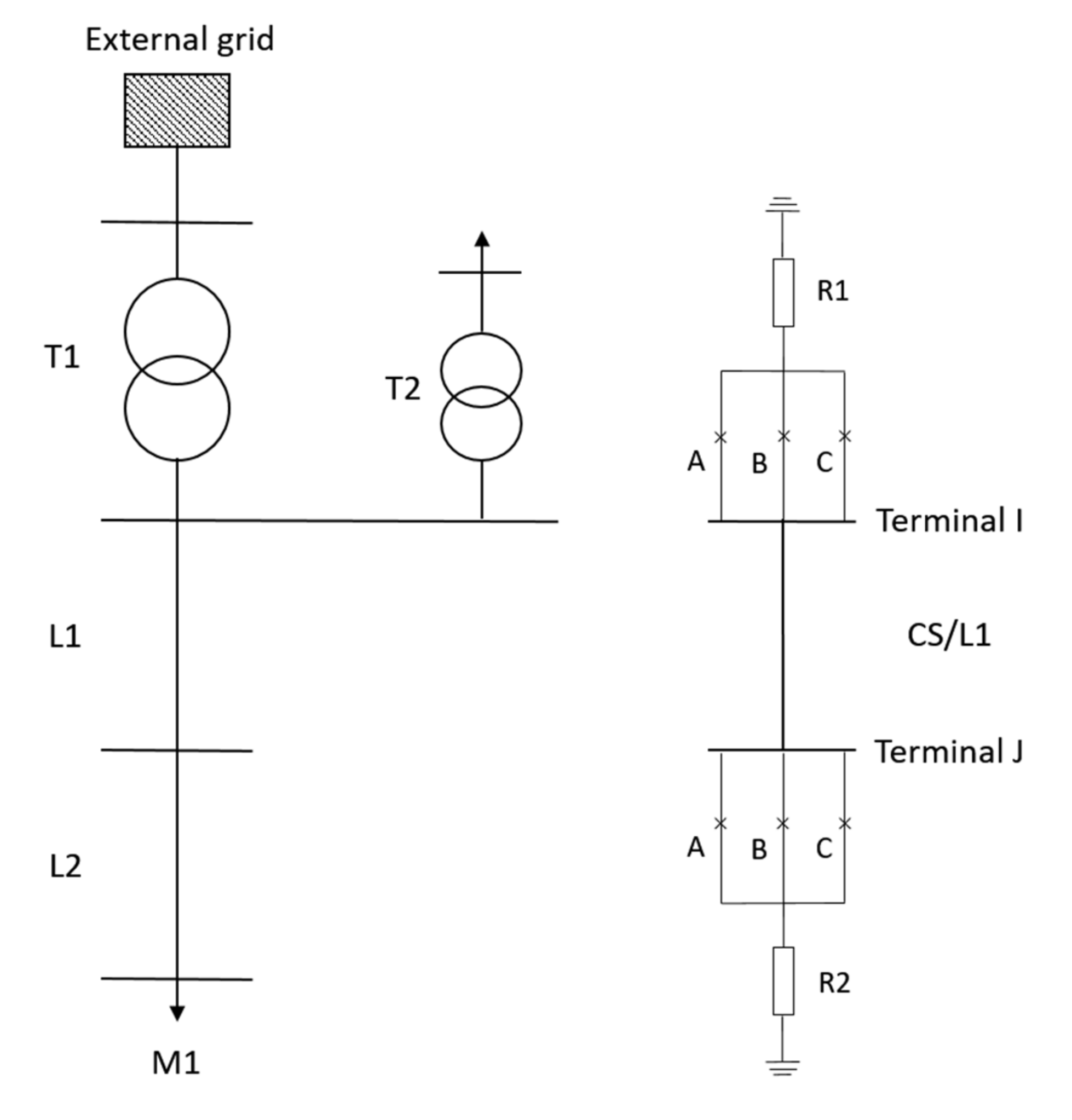
11] was applied, The purpose of the simulations carried out is primarily to get acquainted with the voltages induced in a cable screen; therefore, the model is limited to the cable-overhead MV line connected to the network through the 110/MV power station, where the ground fault necessary for the analysis of the phenomena will be performed in the overhead part. All the constant parameters concerning the model elements are presented in
Table 1, while the variables are described in the following paragraphs. All values of device parameters used to model the system are based on the catalog cards. Particularly important for the creation of the grid model are power transformers [
14], MV cable lines with XLPE insulation [
15], grounding transformers [
16], and overhead line [
17] data, which have been taken from the datasheets available online.
Figure 1 also presents a substitute diagram of the discussed model, which shows the main components of the network under consideration.
According to the literature, sudden changes in the power flow through the network have a significant impact on the occurrence of overvoltages in power devices [
18]. In the case considered in this manuscript, sudden changes will accompany a ground fault in the overhead line that is connected to the cable line. In connection with the adopted layout, device parameters can be distinguished in which changes will not have a major impact on the ground fault current—i.e., those that will remain constant in these considerations and those that may have a significant impact on the network parameters. The second group of these parameters will form the basis for comparative simulation studies that will allow analyzing the impact of changing these parameters on the size magnitude of overvoltages in the network. This group will include values forced by changes in the work of a neutral point grounding system, changes in the three-phase cable arrangement, changes in the cross-section of the conductor and cable screen, and changes in the cable line’s length.
Knowing the model (
Figure 1) and that it has been verified with previous tests, the appropriate way of conducting the research should be chosen, taking into account the tool and simulation methods. The working environment used for simulation studies was the DIgSILENT PowerFactory software for simulating the operating states of the power system and network, which includes the Simulation EMT tool, among others [
19]. It enables simulation studies using the instantaneous values for electromagnetic transient states. For the proper conduct of the ground fault parameters tests, a disturbed parameter cable model was used, and the simulations were performed with an option that allows creating an independent event scenario. For all simulations performed, the event scenario included the following:
Normal operation condition of the system lasting 0.5 s,
Disturbance operation condition, a single phase, no-resistance ground fault in phase A of the overhead line connected to the considered cable line, lasting 0.5 s,
Disconnection of the overhead line and disconnection of the load from the system, lasting 0.5 s.
The object of the research is the cable screens of the three-phase MV cable line and the tested parameter—the voltage appearing at the end of the cable run in individual conductors. The most common work configurations of cable screens, taking into account their grounding, are as follows:
Single-point bonding,
Both-ends bonding without transposition of cable screens and cores,
Transposition of cable screen and/or cores (possible both-ends bonding or single-end bonding).
In the described research, a modification of the both-ends bonding without transposition of cable screens and cores configuration was used, which is the most advantageous from the point of view of the auxiliary role of cable screen but the most heavily burdened from the point of view of losses [
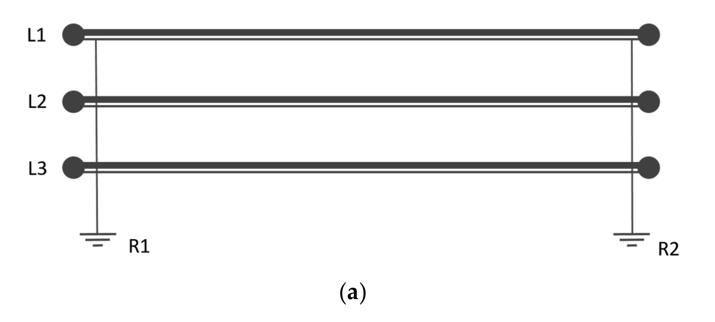
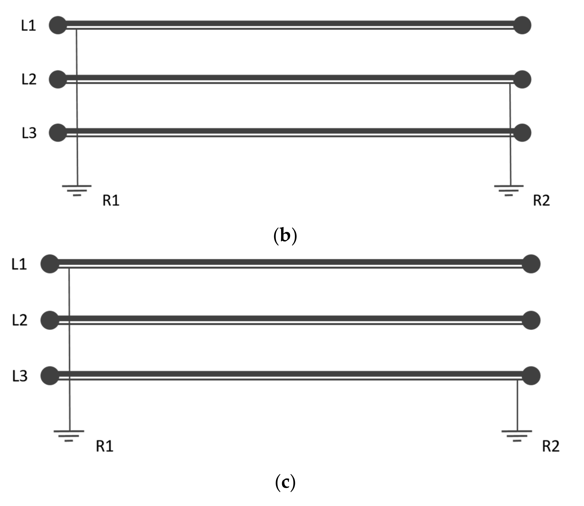
20]. In order to maintain the advantages of this method of operation, it has been proposed to unilaterally unground one or two phases of the cable screen for systems with one cable line per phase. The proposed systems analyzed during the computer simulation are presented in
Figure 2.
The observation of the proposed system requires the selection of appropriate variants of variables that will allow the analysis of the values in this system. The first stage of computer simulations was to compare the proposed work configurations for one-sidedly grounding of one or two phases of cable screens. At this point, it was decided to stay with the variant with only one cable screen phase ungrounded, and the remaining tests were carried out taking into account the following:
Neutral point treatment,
Cable arrangement,
Cross-section of the conductor,
Cross-section of the cable screen,
Length of the tested cable line.
3. Computer Simulation Results
The following section presents the results of the simulation studies carried out with the division into previously described variables and variants. The results are presented in the form of waveforms, graphs of the maximum values of overvoltages, or comparison of maximum values, with an appropriate comment. The basic tested cable, unless otherwise stated, during the simulation is the XRUHAKXS 1 × 120/50 cable in a three-phase, triangular configuration with the length of 1 km. The summary of the outcomes and conclusions are provided at the end of the manuscript.
3.1. Cable Line Configuration
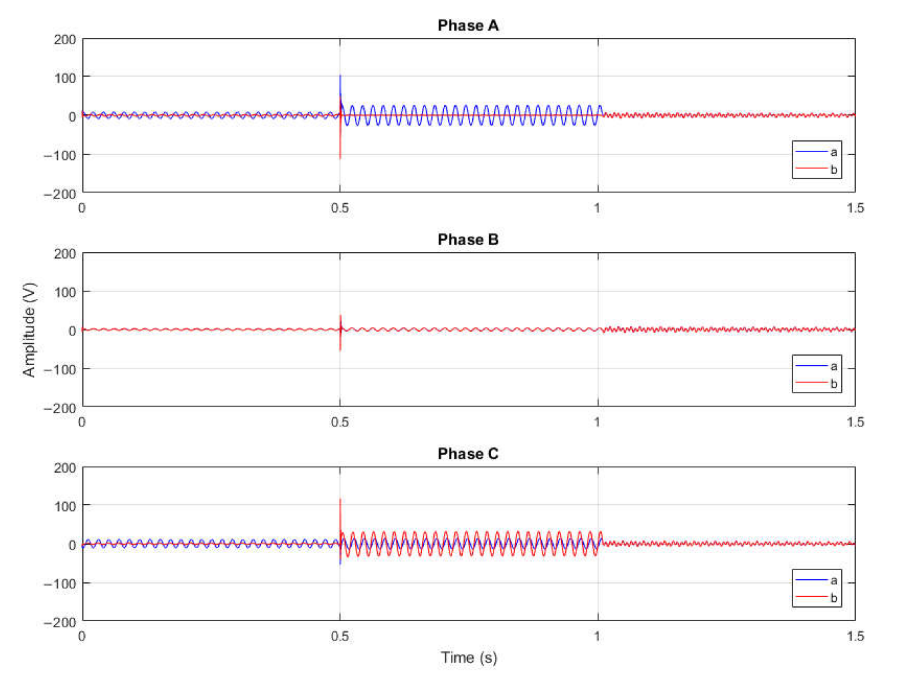
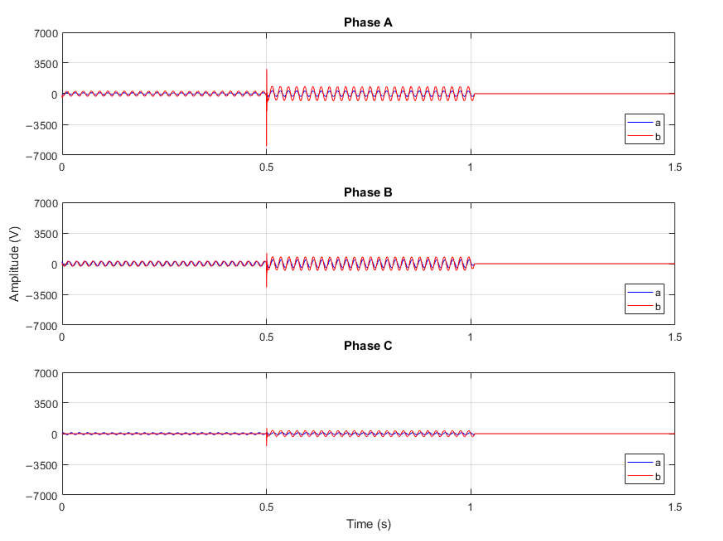
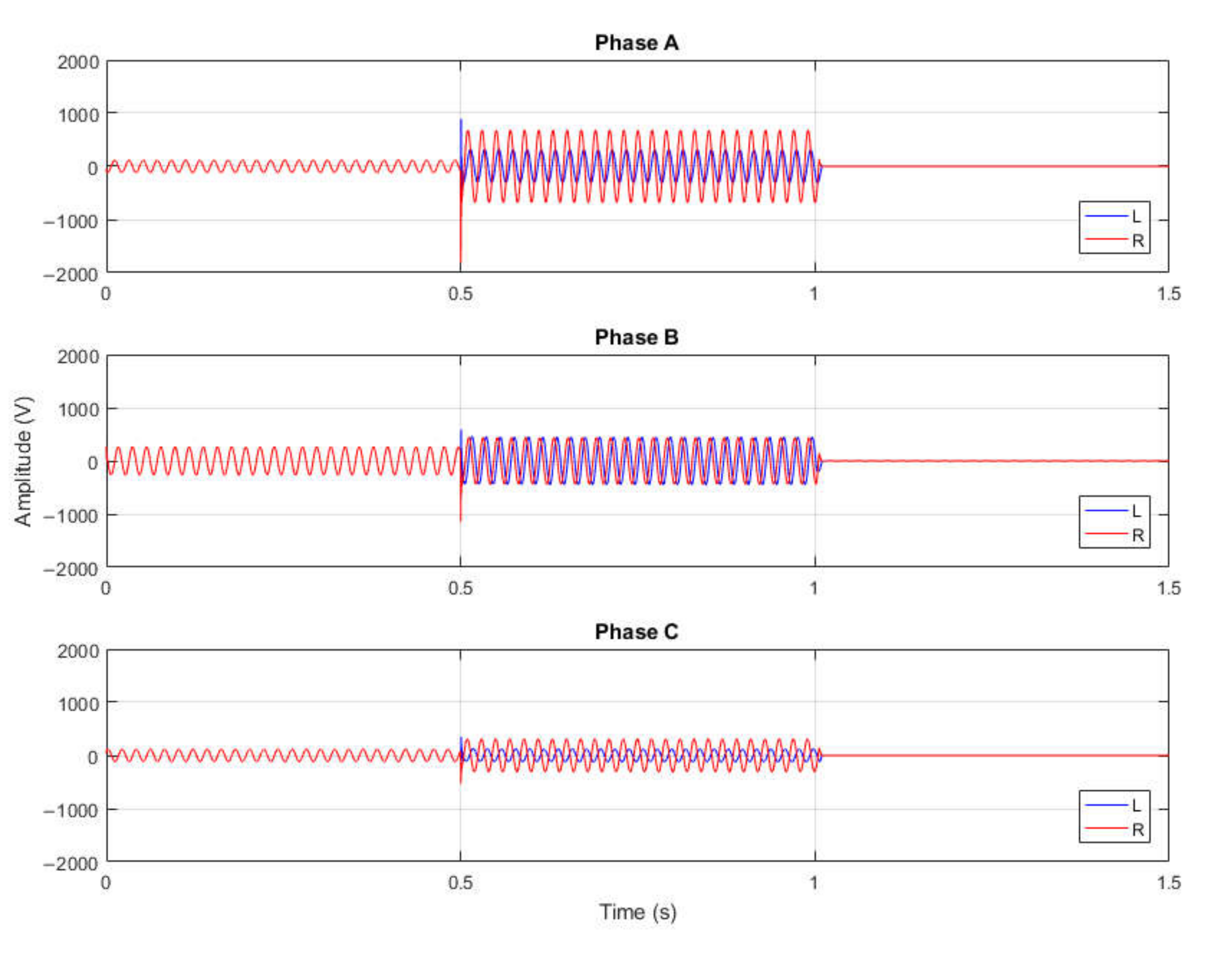
The selection of the configuration of the cable screen’s work, which will ensure safe and reliable operation of the system, is possible thanks to the analysis of the overvoltages at the extreme points of the cable line. These are the places where the cable line is connected to the rest of the network in which it works and where potential transfer is possible. In the layout shown in
Figure 1, it can be seen that the cable is connected to the station, which will be called Terminal I, and it is connected to the overhead line, through the cable heads, in Terminal J. Induced phase voltage in the three phases of the cable screens appearing during a single-phase ground fault I phase A of the L2 overhead line will be presented in
Figure 3 and
Figure 4, respectively, for Terminal I from the station side and Terminal J from the overhead line side as voltage waveforms. The cable screens grounding configurations are also presented and compared on the voltage waveforms. The cable screen grounding methods presented in
Figure 2 are applied as follows:
Method “a”—both-ends bonding with one of the phases one-sidedly ungrounded,
Method “b”—both-ends bonding with two of the phases one-sidedly ungrounded.
In the “a” method, the cable screen of phase A is ungrounded, while in the “b” method, the cable screen of phases A and B is ungrounded.
In
Figure 3 and
Figure 4, separate voltage waveforms in three-phase cable line screens for two methods “a” and “b” are presented. The voltage values that appear during the simulation in Terminal I are significantly lower compared to Terminal J. In this situation, it is worth mentioning that the ungrounding of the cable screens takes place in Terminal J, while from the side of Terminal I, all three phases remain grounded through the R1 resistance. The ground fault current flowing from the fault location, i.e., the L2 overhead line, also flows through the cable line to the station from the Terminal J side. Comparison of the individual waveforms shows that the values obtained during the simulation for both methods coincide, which shows no phase shift, but the voltage values during ground fault duration (from 0.5 to 1 s) for the “b” method are higher, both in the peak and in the rest of the plot. The result of the maximum overvoltages and the conclusions from the obtained values will be presented in
Section 4: Discussion.
3.2. Neutral Point Treatment
As shown in
Figure 1, the network in which the analyzed cable works is grounded through the T2 grounding transformer (parameters included in
Table 1). In the conducted simulations, the variant of operation with the grounding inductor was selected, while in this point, the overvoltages in the network grounded by the inductor or by resistor will be compared. The choice is guided by the actual operation of the MV network and the fact that due to the numerous advantages related to e.g., the operation of protections in the MV network, work with a compensated neutral point is mostly used. However, in the case of the MV network, where there is a larger share of cable lines, it is recommended to use a resistor to ground the neutral point [
21,
22]. The parameters of the grounding devices have been matched to the other network parameters. The cable line is arranged in a triangle, its diameter is 150/50 and the length is 1 km. The discussed in this section and presented on
Figure 5 waveforms are seen from the overhead line in Terminal J.
The presented waveforms show the voltages induced in the cable screens during the ground fault in phase A of the overhead line. As it is shown, the grounding method has quite a significant influence on the voltage waveform, both its value and phase shift. When the neutral point is grounded by a resistor, the ground fault overvoltage is slightly higher in the peak, while the voltage during the duration of the fault, especially for the ungrounded cable screen of phase A, is significantly higher.
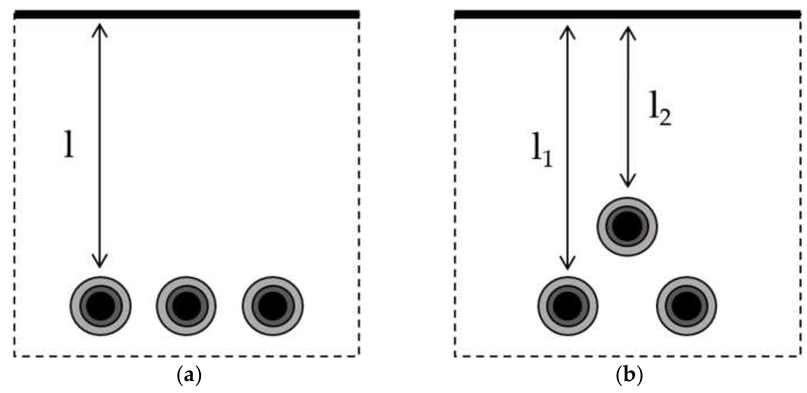
3.3. Cable Arrangement
MV cable lines could work in two arrangement types—flat and triangular, as shown in
Figure 6. Depending on the system in which they work, the induced values in the conductive elements may change due to the influence of individual phases on each other [
5]. The most commonly used system in practice is the flat one, but as a result of possible shifts and movements to the ground, in which the cables are embedded, these configurations may change. A cable arrangement in the three-phase cable line is shown in
Figure 6. At this point, possible differences in the voltage induced in the cable screens during the ground fault were analyzed, assuming the basic parameters of the system. The cable line has a diameter of 150/50 and length of 1 km. In the example, phase A of the cable screen remains one-sidedly ungrounded, and in the same phase, a ground fault occurs in the overhead line.
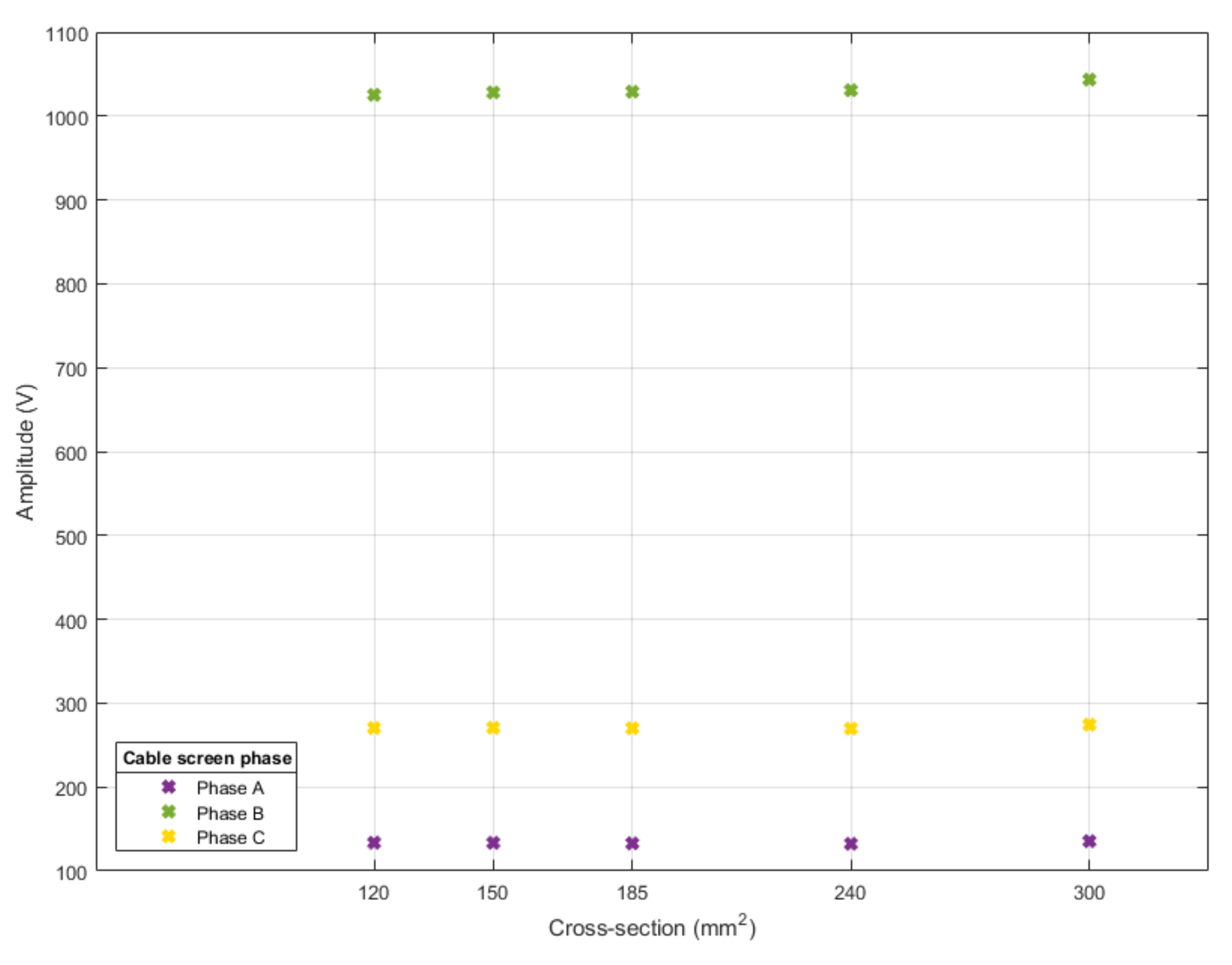
Simulation tests have shown that the change in the voltage level is insignificant from the point of view of overvoltages, and the peak voltage values in ungrounded phase A at the moment of the ground fault occurrence are equal for the flat and triangular arrangement and are 1032 V.
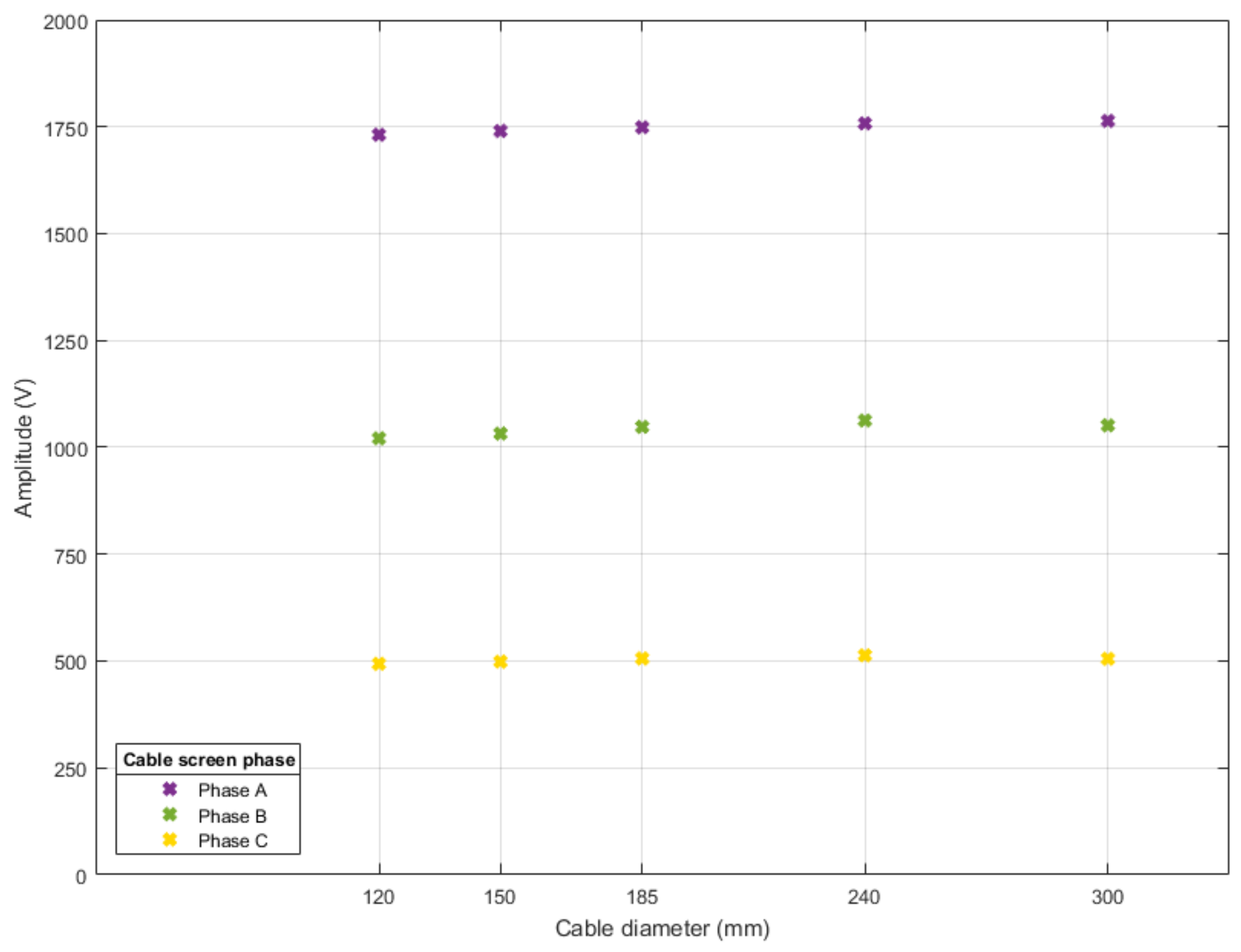
3.4. Conductor Cross-Section
One of the parameters that may affect the level of overvoltages in a cable line is the cross-section of the conductor. For the variant, XRUHAKXS cables with a cable screen of 50 mm
2 cross-section and 120, 150, 185, 240 and 300 mm
2 conductors were adopted. The cable parameters were modeled according to catalog data [
15]. The network parameters are equivalent to those from
Section 3.1, and the configuration of the system assumes the one-sidedly ungrounded cable screen phase. An additional variable in this part of the simulation is the location of the ground fault.
Figure 7 shows the maximum values of overvoltages occurring in the cable line phases during a ground fault in phase A of the overhead line, while
Figure 8 shows maximum values of overvoltages. When the ground fault occurs in phase B, the cable screen of phase A remains ungrounded.
The overvoltage values obtained in the computer simulations appearing in the ungrounded cable screen and in the grounded cable screen show the relationship between the overvoltage level and the cross-section of the conductor in the cable line. The comparison of the values presented in
Figure 7 and
Figure 8 also shows a strong relationship between the overvoltage in the cable screen and the phase in which the ground fault current flows. For the considered example with a fault in phase A, it can be seen that it is in the grounded phase where the highest level of overvoltage occurs, while in case of a fault in phase B, in ungrounded phase A, the overvoltages are the smallest. For all the cores, the maximum overvoltage in the cable screen during the occurrence of the ground fault in phase A oscillates around 1750 V for the phase A, and during the ground fault in phase B, it oscillates around 130 V. However, it can be seen that the voltage changes slightly with increasing the cross-section of the conductor. Maximum values of overvoltages for other phases are included in Table 5.
3.5. Cable Screen Cross-Section
Another variable for simulation is the cross-section of the cable screen of the XRUHAKXS cable with a conductor cross-section equal to 150 mm
2. The other parameters correspond to those selected in
Section 3.4. The two most common cross-sections in practice are 25 mm
2 and 50 mm
2. The computer simulation carried out shows that the comparison of overvoltage waveforms in the form of a figure is difficult due to the overlapping waveforms and voltage values for phase A at the level of U
max = 1744 for the cable screen cross-section of 25 mm
2 and U
max = 1744 for the cross-section of 50 mm
2. Overvoltage maximum values for other phases are included in Table 6.
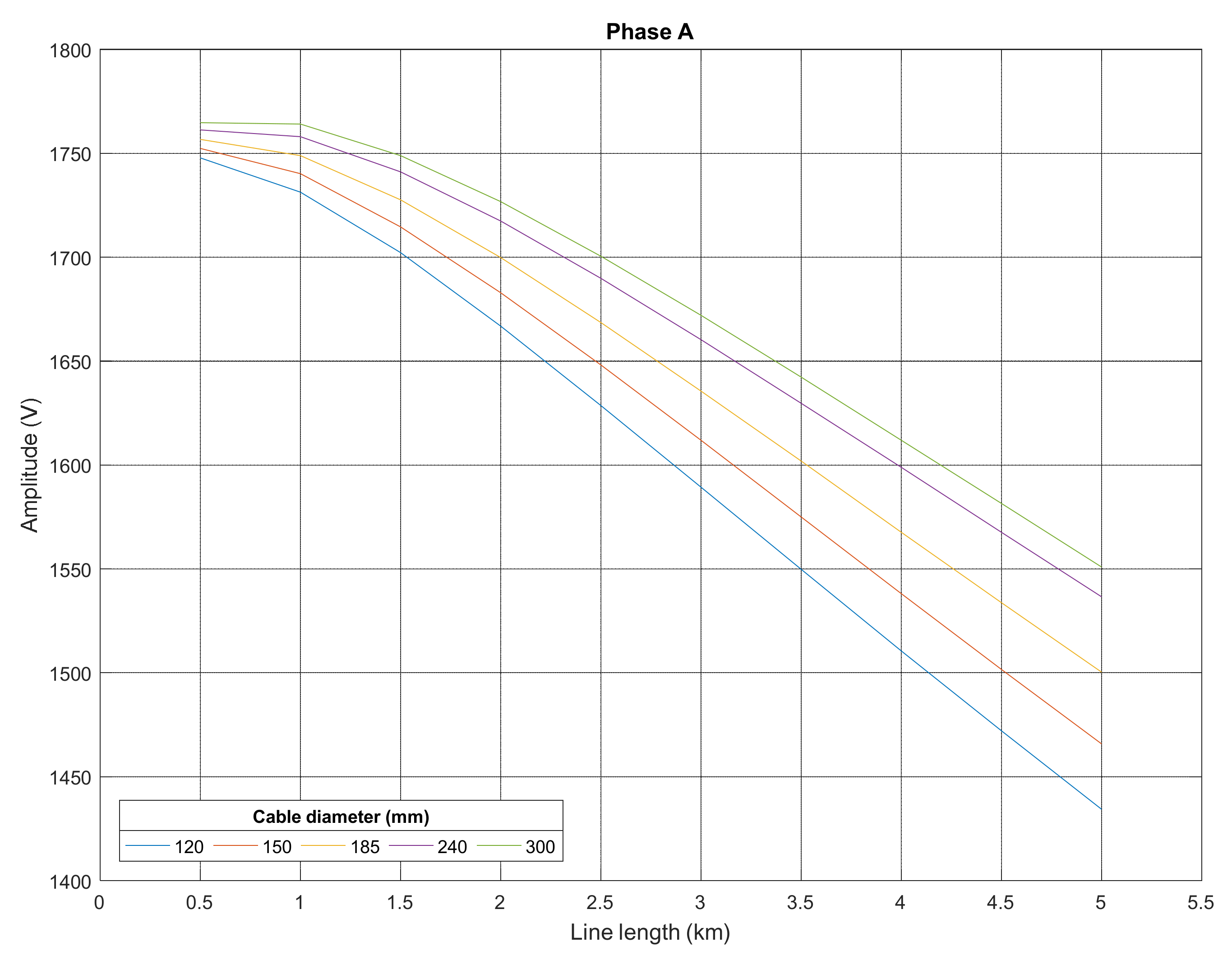
3.6. Cable Line Length
The last variable selected for simulation was cable length. The tests were carried out for a flat cable arrangement with the cross-section of the conductors of the cable as in
Section 3.4 of this manuscript and the cross-section of the cable screen equal to 50 mm
2 for each of the considered cables. The ground fault was simulated in phase A of the overhead line, and the work of the cable screen assumes ungrounding its phase A. The length of the cable varies from 0.5 km to 5 km every 0.5 km. During the simulation, the system operated with the neutral point grounded by the reactor. In connection with the results of the maximum ground fault overvoltages or voltage waveforms in the cable screens presented above in
Section 3.1,
Section 3.2,
Section 3.3,
Section 3.4 and
Section 3.5, only voltages in the cable screen of phase A will be presented and analyzed in this section. This is mainly due to its garment and thus the highest exposure to the high levels of overvoltage among the three phases. Another reason why phase A was selected for analysis at this point is that for the cable screens of the other two phases, the overvoltage does not present such a risk, as they are grounded on both sides. The maximum values of overvoltages for the described cases are presented in
Figure 9.
The diagram presented above shows that the maximum value of the overvoltage for short cable lines up to 5 km long decreases with the increase of the cable line length, and for the range used for the simulation, it ranges from about 1400 V to about 1800 V.
4. Discussion
The computer simulation presented in
Section 3 of the manuscript, which was performed with the use of the MV line model in the DIgSilent PowerFactory program, shows the relationship between the ground fault overvoltages and the basic parameters of the power grid. The presented cases were selected taking into account the current methods of designing and operating the MV network. In this section, tables with summary results of the maximum ground fault overvoltages appearing in the cable screens are presented. This form of presentation of the results may facilitate the assessment of individual options. The assessment will be based on the size criterion. This criterion is based on the electrical strength of the cable screen and assumes that the voltage in it should not exceed 4 kV [
23].
The first simulations concerned the configuration of cable screen connections and showed the shaping of overvoltages in terminals to which the cable is connected. In accordance with the results obtained for individual terminals, it was found that the highest overvoltage values appear in Terminal J, in which the cable screen is grounded, and therefore, further overvoltage simulations were performed at this point. Moreover, based on the results of this simulation, which are presented in
Table 2, only the configuration with a one-sidedly ungrounded cable screen of phase A (
Figure 2b) was taken into account for further considerations. For the configuration with ungrounded cable screens of phases A and B, the overvoltage values, especially in phase A where the ground fault occurred simultaneously, are much greater than the value adopted as the evaluation criterion.
The next research looked at the effect of how the neutral point works. The results for these simulations are presented in
Table 3. With the ungrounded cable screen of phase A, the overvoltage values did not exceed 2 kV, but it is clearly visible that for the network with a neutral point grounded through a resistor, the overvoltage values are higher. This is a very important observation, because when designing cable networks, it is recommended to ground the neutral point of the network through a resistor [
22].
Subsequent tests concerned parameters related to the cable’s construction and method of its laying.
Table 4 shows the maximum overvoltages for the flat and triangular systems. As can be seen, these values for the cable screen in any phase, regardless of grounding configuration, do not exceed the size criterion, but they also do not change significantly, which leads to the conclusion that the cable arrangement will not affect the overvoltage value.
Table 5 and
Table 6 summarize the results of the maximum overvoltage values for the systems with different cross-sections for the conductors but also with different phases in which ground fault occurs. As can be seen from the example with the ungrounded cable screen of phase A, when the ground fault occurs in an ungrounded phase (
Table 5), the overvoltage values are apparently the highest for this phase. In the case of the ungrounded cable screen in phase A, but the ground fault in phase B (
Table 6), the overvoltage value is insignificant. On the basis of these results, it can be also concluded that the cross-section of a working conductor only slightly influences the maximum overvoltage. Similar conclusions can be drawn by comparing the results in
Table 7, which lists the maximum voltages for cables with cross-sections of cable screen of 25 mm
2 and 50 mm
2. Again, the cross-section of this element is not important from the overvoltage point of view.
The last simulations are the output of all previous simulations. For the ungrounded cable screen of phase A, in which the ground fault occurs, with the same cross-section of the the cable screen, a neutral point grounded through the reactor, and different cross-sections of conductors, the influence of the line length on the overvoltage is shown. Based on the results presented in
Table 8, it can be concluded that short cable lines are particularly exposed to high overvoltage values.
5. Conclusions
Summarizing the results for the overvoltages in the cable screens obtained as a result of computer simulations and taking into account the dependencies described in the Discussion section, conclusions can be drawn about the influence of the parameters of the variables selected for consideration in the described model. According to the analysis of the phenomena, it can be concluded that the one-sidedly ungrounding of one of the cable screen phases causes the possibility of an overvoltage hazard for the ungrounded cable screen phase, regardless of other conditions in the network. However, these conditions may have an impact on the level of these overvoltages and, knowing these dependencies, it is possible to use this method of cable screen operation. The manuscript adopted the limit values of the ground fault overvoltage equal to 4 kV; however, taking into account, for example, the issues of protection against electric shock and the possibility of transferring potentials, this value can be freely adjusted to the application, and thus, it will be possible to determine the correctness of the cable screen’s ungrounding. Therefore, the assumptions presented here must also consider the conditions of protection against electric shock and safe voltage levels in a cable network, where these requirements are much lower than in the case of an overhead line. In general, if one-sidedly ungrounding of the cable screen phase will be used, it is suggested to equipped this phase with a spark-gap surge arrester to ensure safe operation of the system.
In connection with the obtained results, it can be assumed that these are not all the variables that should be considered in the overvoltage study. In the described case, the network structure is very limited and it has minimal load. If the load is increased, the current flowing to the power supply can have a significant effect on the overvoltage that occur in the cable screen. In further works, the dependence of the overvoltage value on the current load of a given cable line should also be considered. It also seems important to find the place where the ground fault occurred and to check what the impact on the overvoltage would be if the ground fault changed its place from overhead line to cable line.


