1. Introduction
According to the World Health Organization records from 2011, about 15% of the world’s population lives with some kind of identified disability and about 4% of these people live with some kind of serious functioning disorders [
1,
2]. However, people who want to work among people with disabilities are also in high demand. Our society needs to take into account the needs of the individuals and enable them to grow personally, to develop themselves and to work. A job and regular income is a basic parameter for the inclusion of an individual in society and in in social life and also contributes to healthy mental health. According to a study [
3] in the United States alone, 34.9% of people with disabilities work, compared to 76% of their non-disabled counterparts. The inability to get a job, as a rule, negatively affects the emotional and financial state of these people. For people with limited possibilities due to their disabilities, it can be helpful to fulfill their life and help them to feel like they are fully involved in ordinary society. In addition, many people with physical disorders have a relevant education. Thus, organizations do not need to train people in the processes from the very beginning, but can benefit from their technical background. For example, in 2019 in the United States, among the 38 million people at the age of 25 years and older who suffered from an identified disability, 6.7% of them possessed a bachelor’s degree [
4]. According to Eurostat [
5], in the European ICT market (information and communication technologies) for 2019, the shortage of specialists was 55%. In 2020, the main sector with vacant job positions was production and manufacturing. If the technical parameters and the possibility of getting decent jobs for people with limitations were met, these job positions could be filled.
One of the main problems in involving people with disabilities in the production process is the problem of their interaction with the equipment that is used in industrial environments. Therefore, to involve these people into the process, interfaces are needed to be developed, which will, on the one hand, compensate for their physical limitations, and on the other hand, allow them to interact with production equipment at the required level of functionality and safety for both production workers and the production process. The design of such an interface requires something unconventional and new. The currently used HMI (human machine interface) panels may not be enough. They require manual reactions, pressing buttons, and controlling processes by touch. This study should serve as a proof of concept, that even people with various physical disabilities can be successfully employed and can safely use various equipment in an industrial environment.
Movement is mainly controlled by the central nervous system. One of the methods of reading signals suitable for motion control is the use of non-invasive BCIs that allow for the reading of the electrical activity of the brain, namely the surface of the neocortex. For example, in Ref. [
2], the authors Leila Mohammadi, Zahra Einalou, et al., investigated the possibility of cursor control using non-invasive BCI. They used the K-means clustering method to recognize the available hidden patterns in each of four modes or movements: up, down, left, and right.
Non-invasive BCIs are now widely used and these devices allow us to read electrical potentials of different levels from different zones of the neocortex of the human brain. The surface of the neocortex is divided into four functional parts: frontal, parietal, temporal, and occipital parts [
6,
7,
8]. BCIs’ potential is to create a new communication channel between the brain and an output device. It uses signals recorded from the human scalp, the surface of the mentioned cortex. In this way, users can control a variety of applications including, for example, simple word-processing software. In the future, BCI technology could be used as a new communication and control option for humans who cannot otherwise express their wishes or commands [
9]. Therefore, essential tools like signal processing and classification methods are very necessary for improving and revealing the possibilities of BCI technologies.
In our research, we have decided to pick the BCI method out of other methods like Magnetic Resonance Imaging (MRI), Transcranial Magnetic Stimulation (TMS), Positron Emission Tomography (PET), etc., because of various factors. The BCI method is safe for the subject, because it is a non-invasive method. It is also more accessible with regard to budget and also to permissions than other methods which require special medical training.
There are many different approaches to control movement using neocortical signals. One of the approaches is based on reading signals from the motor–sensory cortex of the human brain, discussed in Ref. [
10]. Movement control can also be achieved by reading signals from the occipital lobe, which is more involved in visual information processing [
11]. The authors reported on the distinct time courses of cortical activation in dyslexic and control subjects during passive viewing of single words, tracked with whole-head magnetoencephalography. A striking difference was found in the left inferior temporo-occipital region, where intracranial recordings have recently identified word-specific responses within 200 msec after stimulus onset [
11]. There are also combined methods that involve the processing of significant signals from different areas of the brain. For example, the Refs. [
12,
13] considered a combined technique based on the processing of signals from the motor–sensory and occipital cortex simultaneously. In this articles, the authors used advanced noninvasive neuroimaging techniques such as EEG and fMRI (functional magnetic resonance) that allowed them to directly observe brain activities while subjects perform various perceptual, motor, and/or cognitive tasks. The authors declared that neuroeconomics will fully reach its potential by addressing several theoretical and methodological challenges [
13].
Recently, many studies have appeared that describe and classify brain activity using brain waves as possible [
14]. The authors created a functional prototype that can use human EEGs to control the snake in a game with over 90% accuracy. In this experiment, two mental tasks were used to separate between turning the snake left or right: baseline (thinking nothing in particular) and mental counting [
14]. A brain wave can be called an electrical map of the brain. The main types of brain waves are alpha waves, beta waves, gamma waves, delta waves, and theta waves, which are found in the ranges of 8–13 Hz, 13–30 Hz, 30–100 Hz, 0–4 Hz, and 4–8 Hz, respectively. In this article, the authors used the Emotiv Epoc device for their experiment to analyze EEG data [
15]. This also confirmed that there is a huge interest in this field of study and various devices can be used for obtaining EEG data.
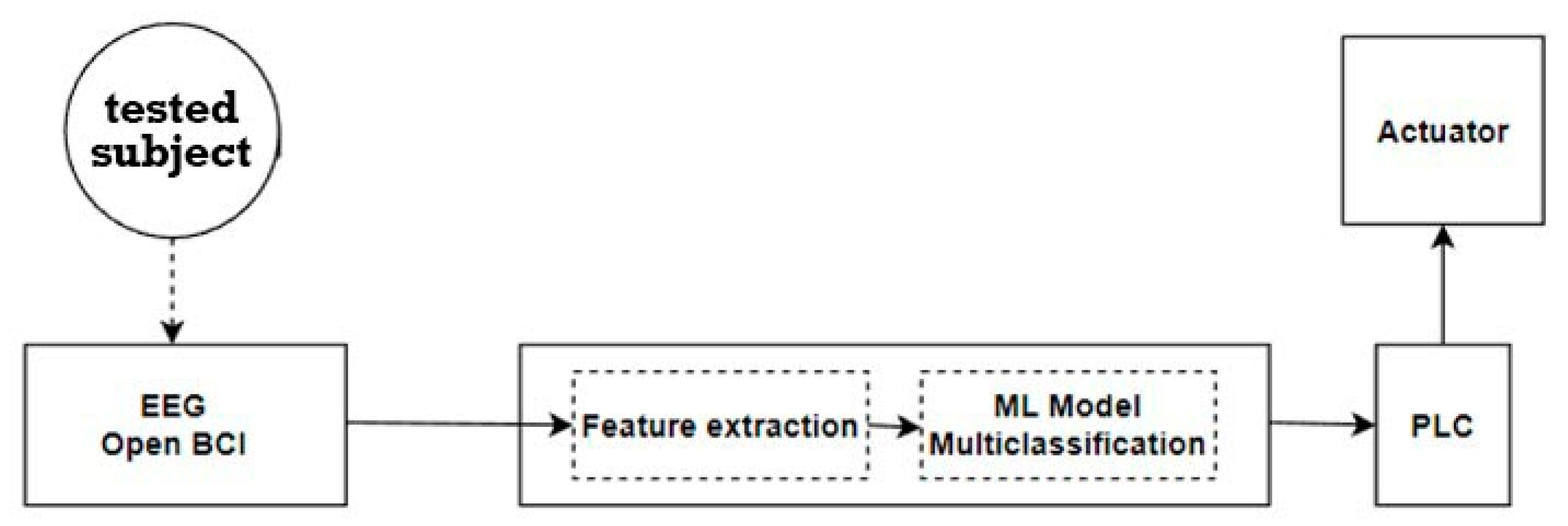
The purpose of this study is to evaluate the feasibility of creating a controller for a simple manufacturing process using signals obtained using non-invasive BCI. The sensorimotor cortex is mainly responsible for the control and planning of human movement. Additionally, the task of the study is to show the possibility of controlling the production process in real time, which will allow the user to control the process without physical contact. All subjects completed this task successfully. In this study, different machine learning algorithms were used to identify patterns of brain activity corresponding to a particular command that activates specific outputs on the PLC, and subsequently the actuator itself. Four machine learning algorithms were tested (including logistic regression and several boosting algorithms), and all showed 100% accuracy in team identification under the given experimental conditions. This is due to the fact that the signals for each state/command were in different ranges and did not have cross zones, which allowed the models to correctly guess the commands after training on the training data. It should be noted that with the expansion in the range of commands, the identification accuracy may decrease.
Although the proposed solution in current state is not ready for real applications, it serves as a proof of concept for using BCI interfaces in the industrial environment. The main goal of this paper is to present the possibility and framework for identifying simple commands from the data collected via BCI and subsequently using them to control industrial equipment.
With a sufficient expansion in the range of commands and a decrease in the reaction speed of the actuators, it is possible to use the system in real production, at least for two purposes:
(1) Control of the actuator or part of the production process or part of the conveyor without physical contact in manual mode.
(2) Testing the functionality of the selected actuator or part of the production process to identify problems encountered during operation.
These two tasks could potentially be solved by people with physical disabilities using the BCI and PLC interfaces connected to each other [
16,
17].
3. Results
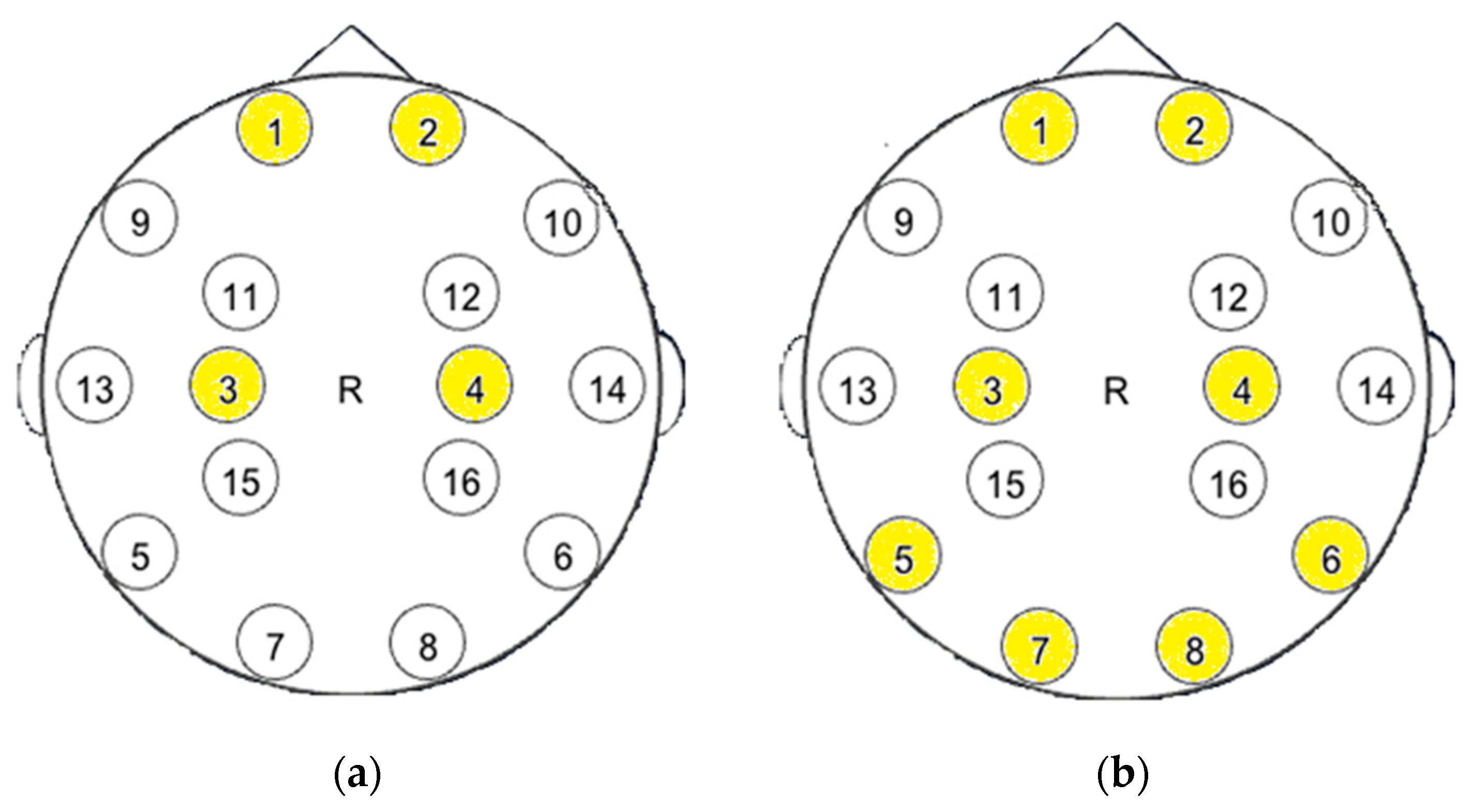
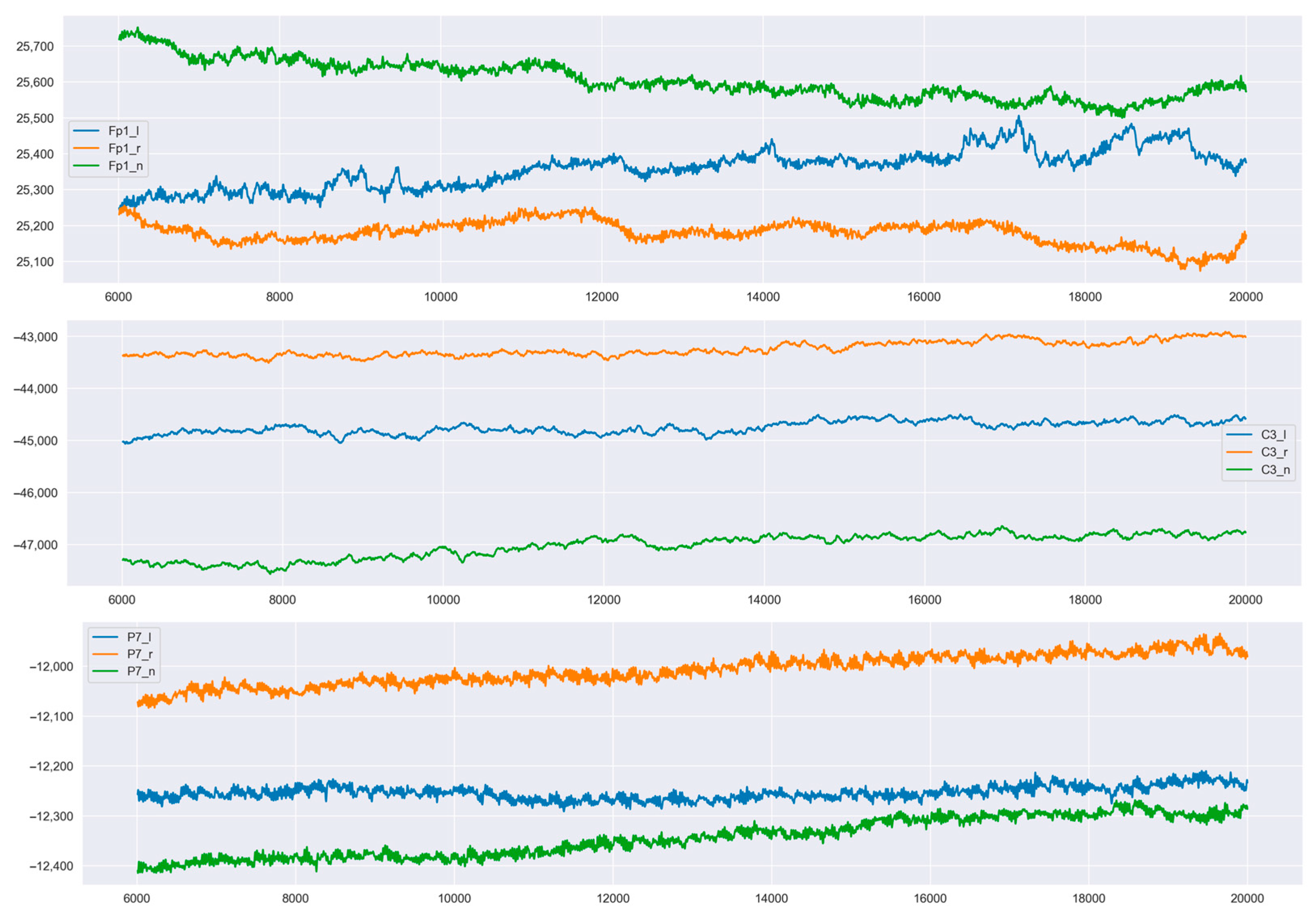
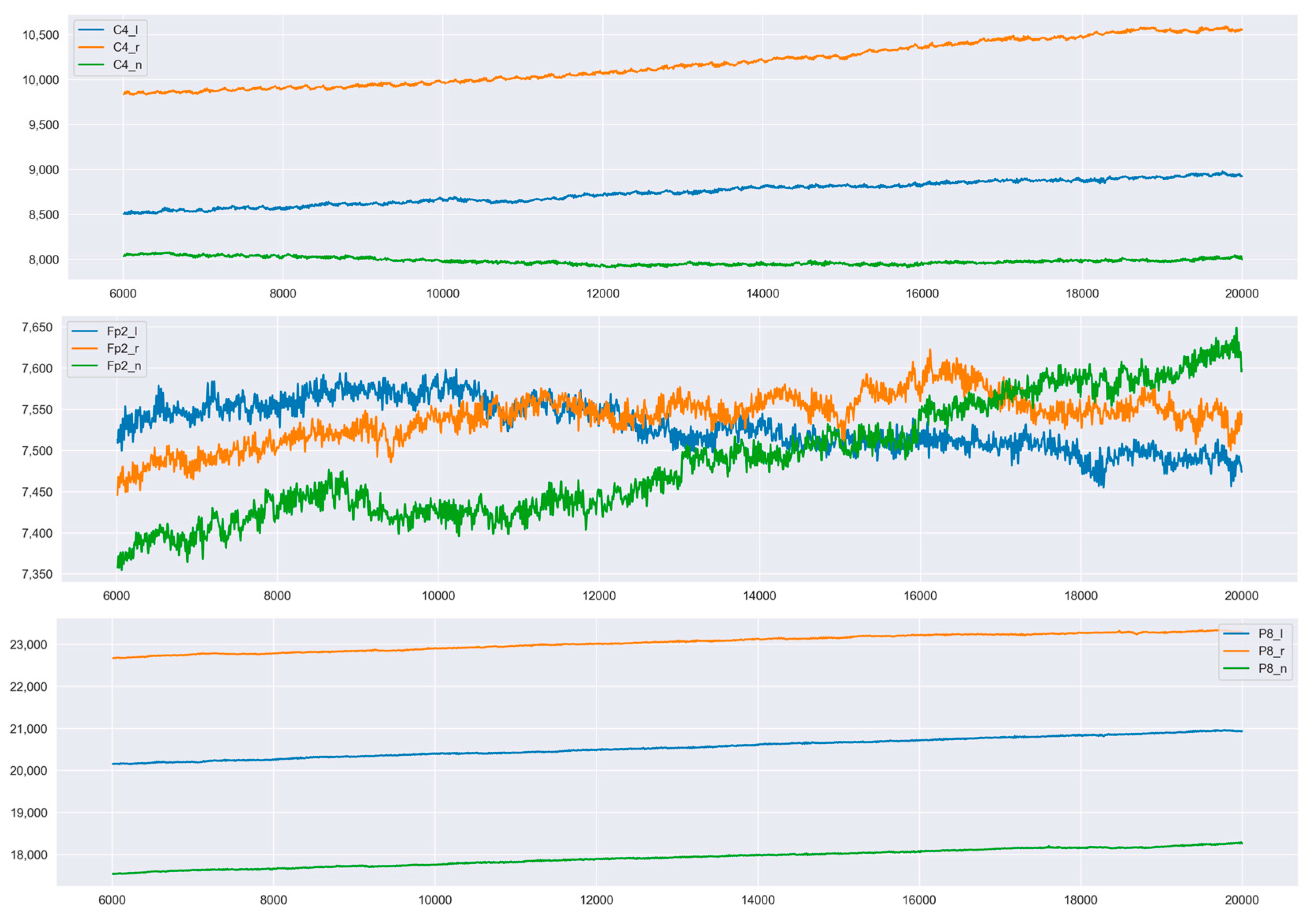
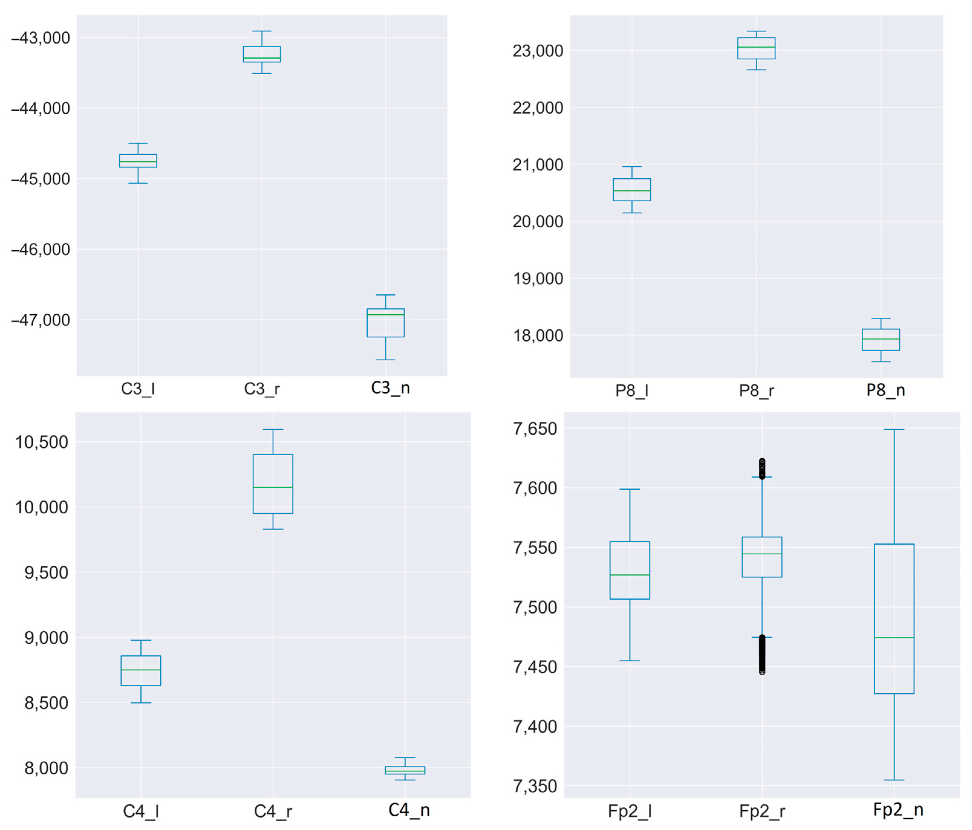
Figure 5 and
Figure 6 show the three channels for six sensors of one of the subjects. Fp1, Fp2—frontal lobe left and right. C4—near the parietal lobe. P7, P8—occipital lobe closer to the midline. 02—occipital part.
For each signal from each sensor, the same time interval was taken. Thus, it was possible to superimpose signals for different states from one sensor on one graph. It can be seen that the signals for different states (left, right, rest) have intersection areas for only one sensor.
The states from the FP2 sensor, which was located on the front right side of the neocortex, had the least variability. It is difficult to say what exactly is the reason for such a reaction in the right frontal lobe (this reaction requires additional research).
The sensors did not change their location during the full session of the experiment. It is clear from the graphs that the focus on different teams or states was different. Significant intersection of signals occurred only in one case: when receiving signals from the FP2 sensor.
A clear separation of signals can be traced in all subjects, although the levels of signals from each subject differed.
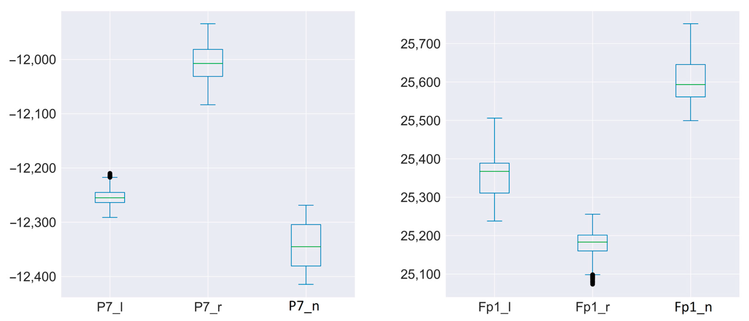
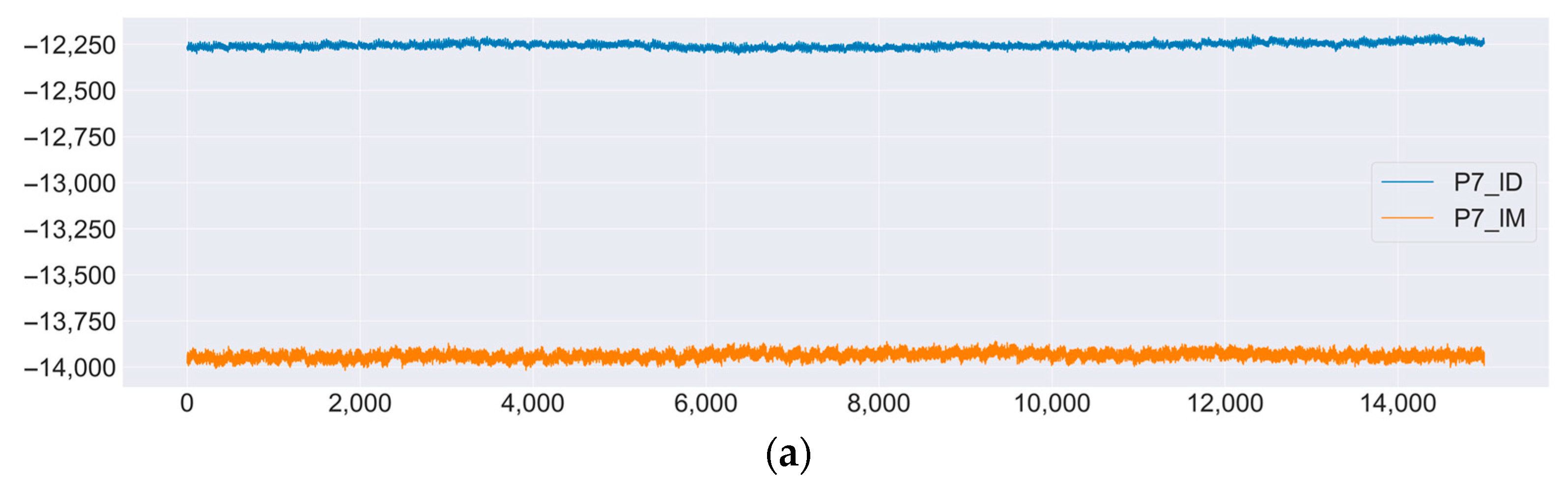
In
Figure 7, there is a comparison of the signals for two subjects for the same commands from the same sensors. As can be seen from the graphs, for the two participants in the experiment, there was a clear separation for each type of signal.
4. Discussion
Based on BCI, a simple drive control system via PLC was developed. All participants were able to successfully control the drive after pre-training the model on individual user data (
Supplementary Materials). Additionally, all subjects were able to quickly enter a state of rest before the experiment. However, in the future, one of the subjects, when concentrating on one of the commands, involuntarily set in motion the left or right hand. Thanks to visual control, it was possible to establish this and conduct a repeated series of experiments in order to exclude involuntary physical movements.
During the experiment, several tasks were recorded, the study of which is possible in future experiments.
Although the data received from the sensors clearly identified each command, the signal levels were different for each user. In this case, it was necessary for to collect individual data for each participant in the experiment and retrain the model in order to accurately identify the commands. The difference in signals can be associated both with the individual characteristics of the participant, and with a small difference in the location of the sensors relative to the neocortex zones. More precise positioning of sensors is discussed in Refs. [
18,
19].
Additionally, the problem of different signal intensities can be associated with different emotional and physical states of the participants. In future experiments, it is possible to additionally control the state of the participant by measuring their pulse during the experiment, as was done in [
20,
21]. This study looked at the relationship between resting heart rate variability and performance with the P300-BCI.
Secondly, despite the successful results of the experiment, the control of the actuator was not fully implemented. The drive has two degrees of freedom. There is also an invader feature. Extending the drive control with these functions will allow us to talk about the full control of the drive (for manual control mode). Modern BCI systems using SSVEP [
16] can contain up to 15 commands. However, for hybrid BCIs using P300 and SSVEP, more than 100 command codes have been implemented [
17]. The question also arises about the long-term use of such control, because in total, each session was no longer than 12 min. It is possible that as the session grows and the number of possible commands increases, the accuracy and speed of switching between commands will deteriorate.
5. Conclusions
This study was devoted to the design and implementation of using EEG signals for control systems for robotic arm control. We have focused on building the bridge between human biosignals and machine control.
In this study, a control system for a simple production arm using BCI and PLC was designed and tested. All subjects were able to successfully operate the manipulator, although individual system settings were required for each subject. Mastering the necessary commands for control was quite easy, and none of the subjects had problems focusing on one of the three states. Breaks between two key states, according to the subjects, made it is easier to focus on the task following the relaxation phase.
However, in order for the system to potentially be used in production, it is necessary to reduce the break time between commands for the actuator. Additionally, it is necessary to expand the range of commands so that they cover the full range of possible actions of the manipulator. In addition, the system should be more versatile in terms of reconfiguration for each new user, i.e., reconfiguration time should be reduced to a minimum or, if possible, this process should be avoided altogether.
Finally, it is necessary to conduct testing with persons with impaired motor functions, since they are the intended end users of the system.


