
A Cost-Effective Lightning Current Measuring Instrument with Wide Current Range Detection Using Dual Signal Conditioning Circuits

Abstract
:1. Introduction
- Lightning current detection range is 500 A to 100 kA;
- The polarity of the lightning current should be distinguishable;
- The lightning current detection time and date must be known;
- Real-time remote monitoring should be provided through Ethernet communication;
- The product must have portable memory, and the lightning current detection data must be stored;
- International standard on waterproof and dustproof (IP code) is IP43 or higher.
2. Materials and Methods
2.1. Mechanical Design
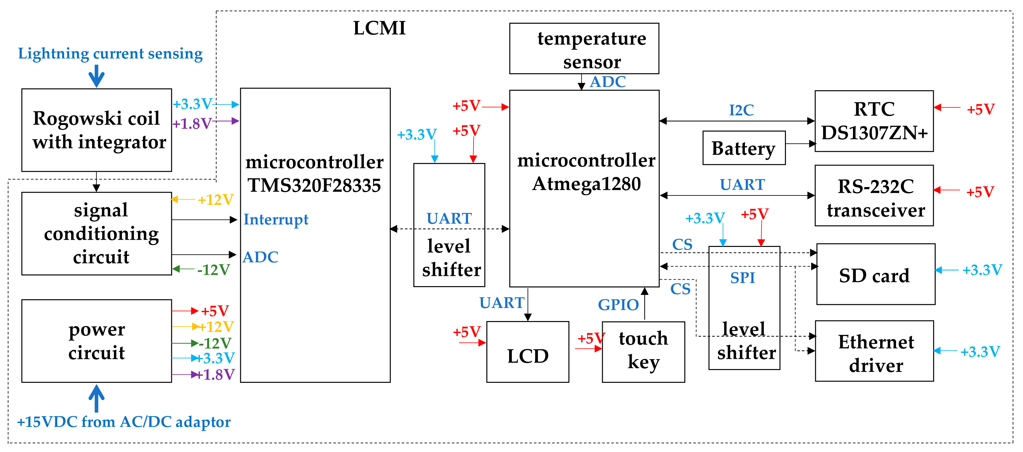
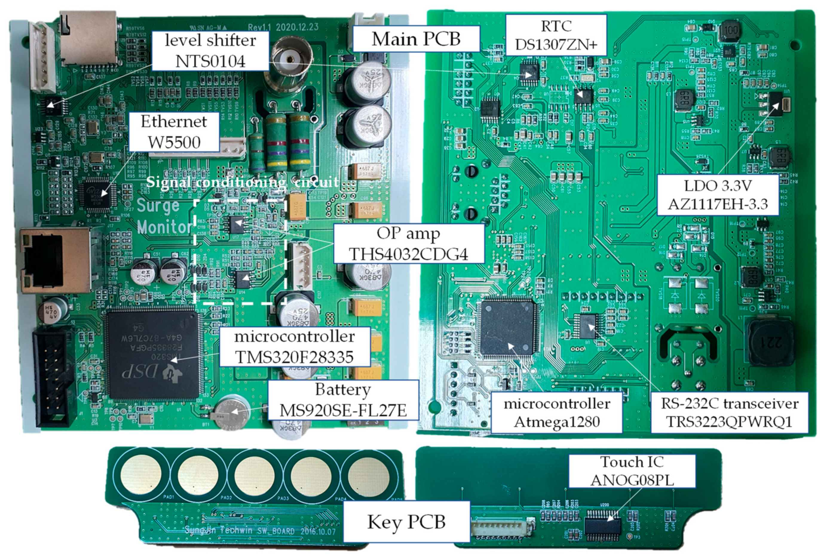
2.2. Block Diagram
2.3. Lightning Current
2.3.1. Classification of Lightning Current
2.3.2. Lightning Current Analysis
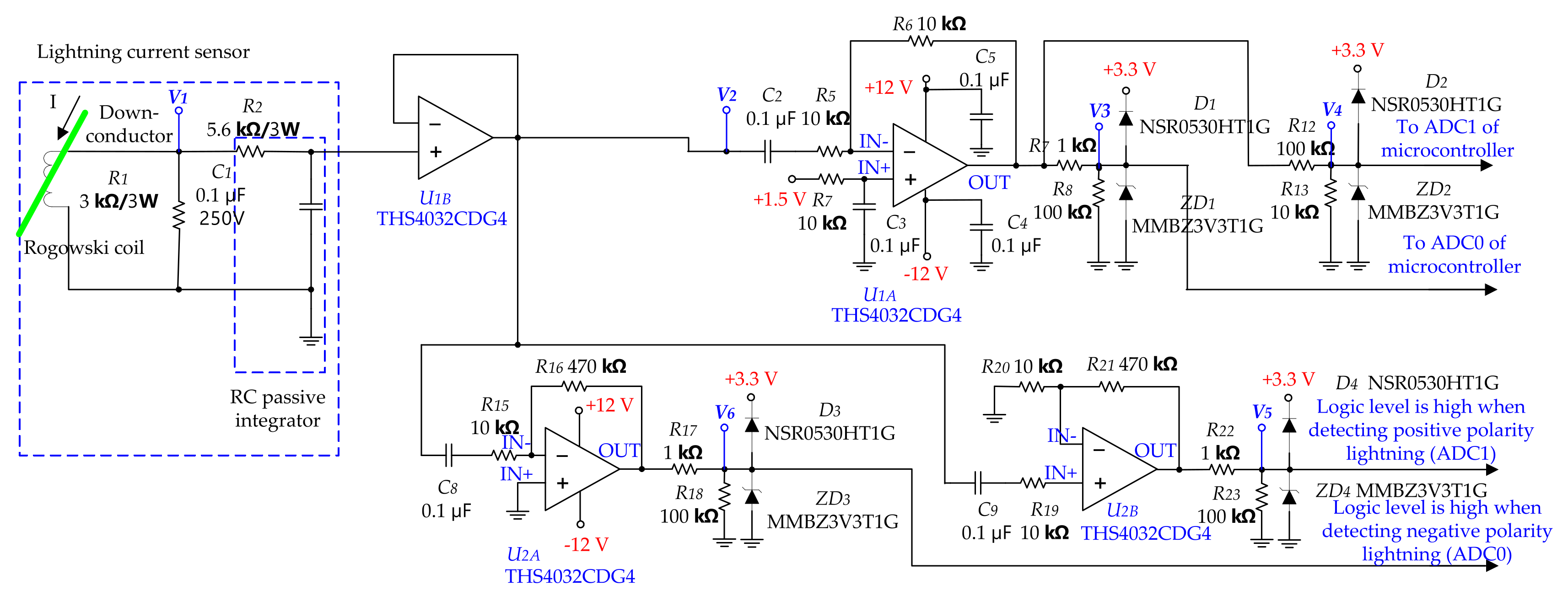
2.4. Rogowski Coil Current Sensor and Signal Conditioning Circuit Design
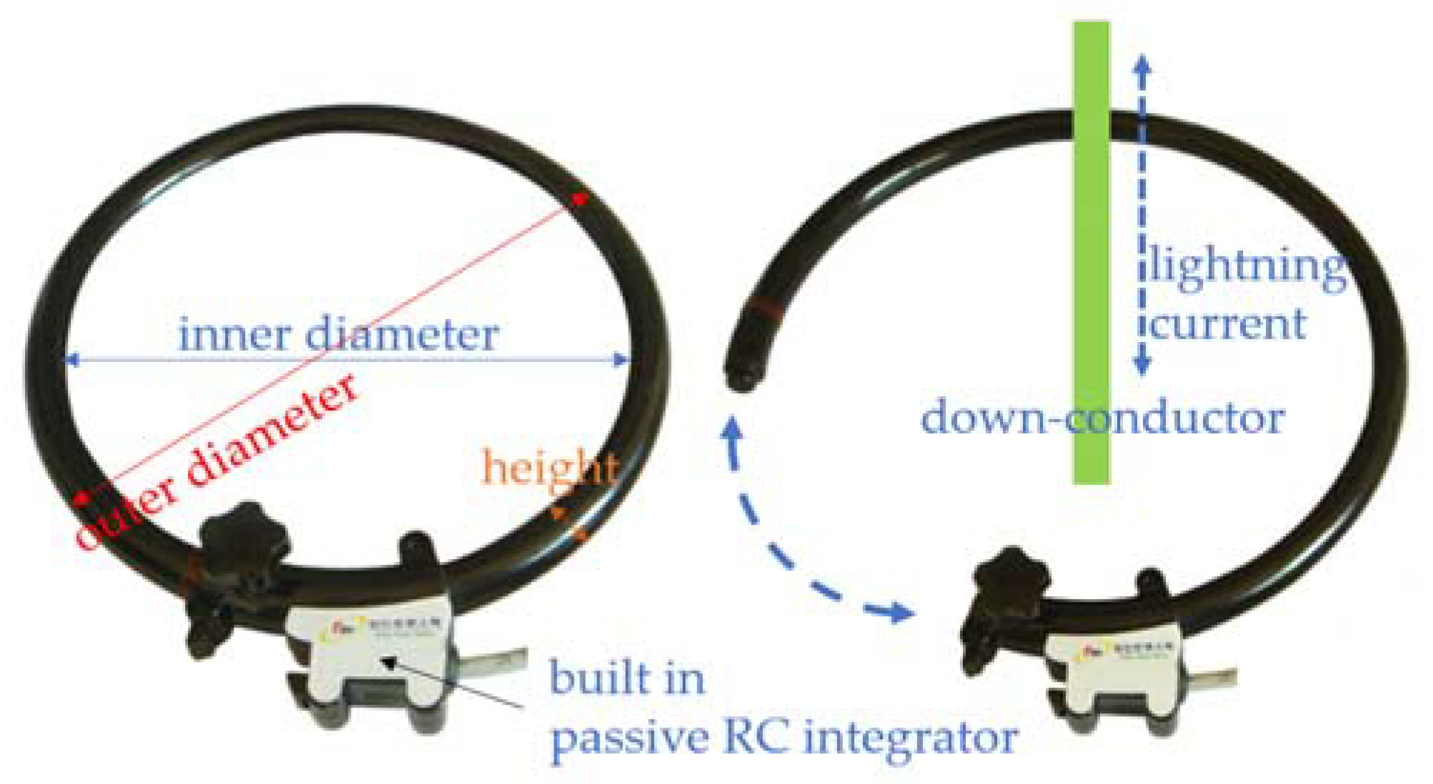
2.4.1. Rogowski Coil Current Sensor
2.4.2. A Signal Conditioning Circuit Capable of Detecting Lightning Current from 500 A to 100 kA
- ultra-low 1.6 nV/√Hz voltage noise;
- high speed (100 V/μs slew rate);
- low 0.5 mV (typical) input offset voltage;
- 100 MHz band width.
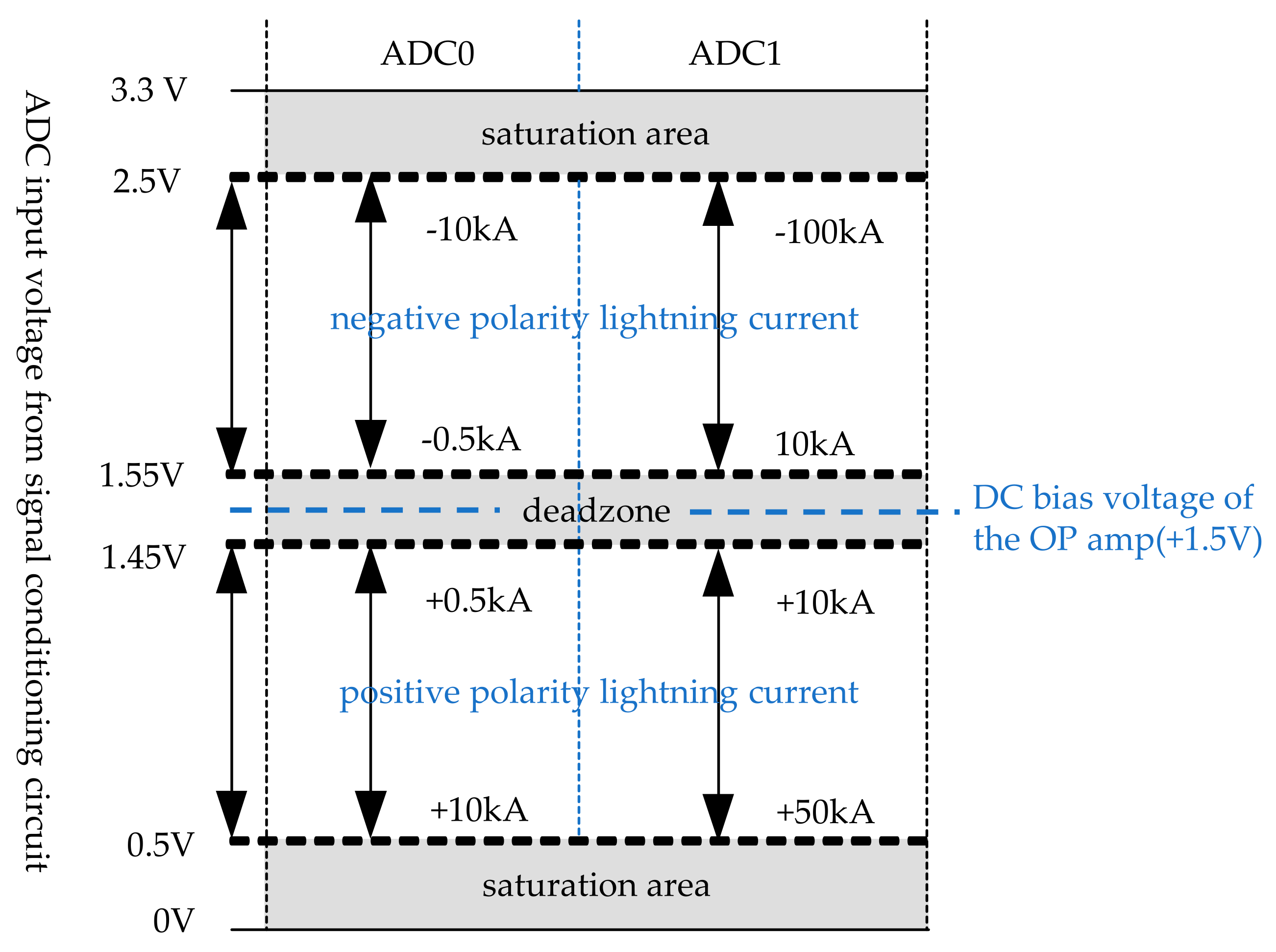
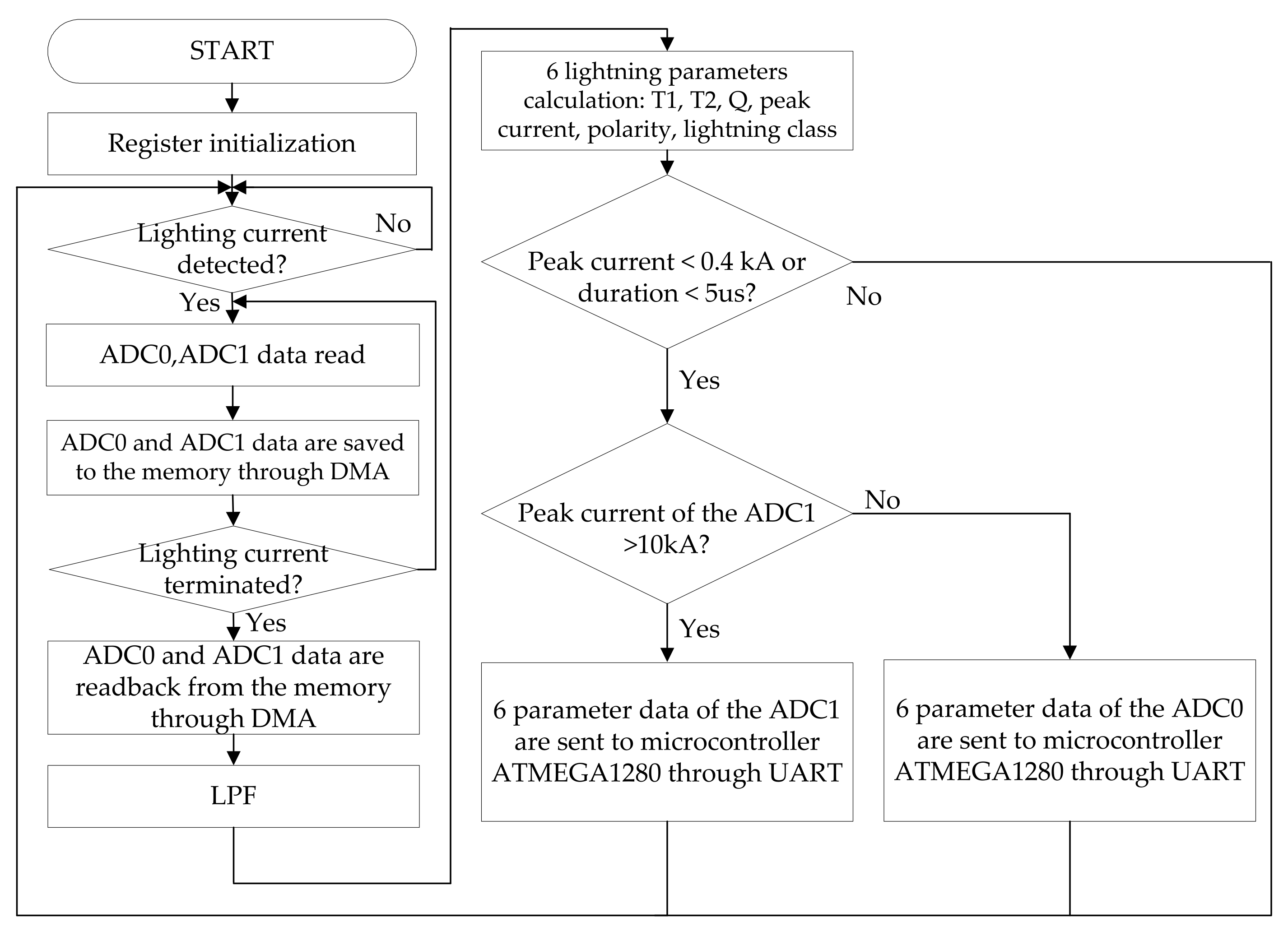
2.5. A Signal Processing Software Algorithm of the Microcontroller for Lightning Current
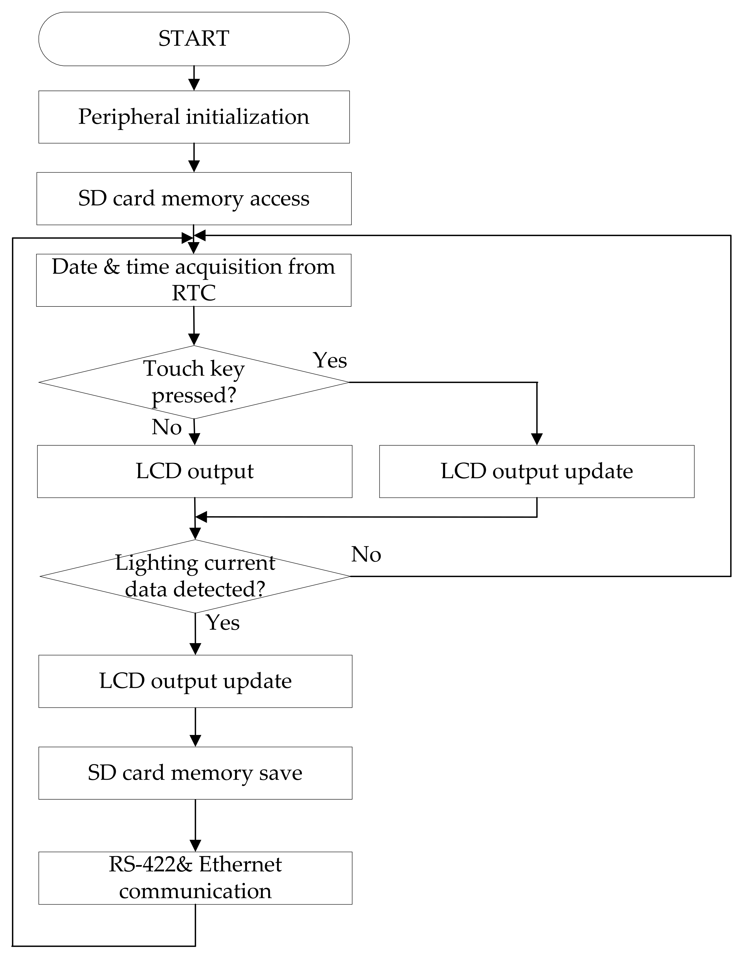
2.6. A Software Algorithm of the Microcontroller (ATMEGA1280)
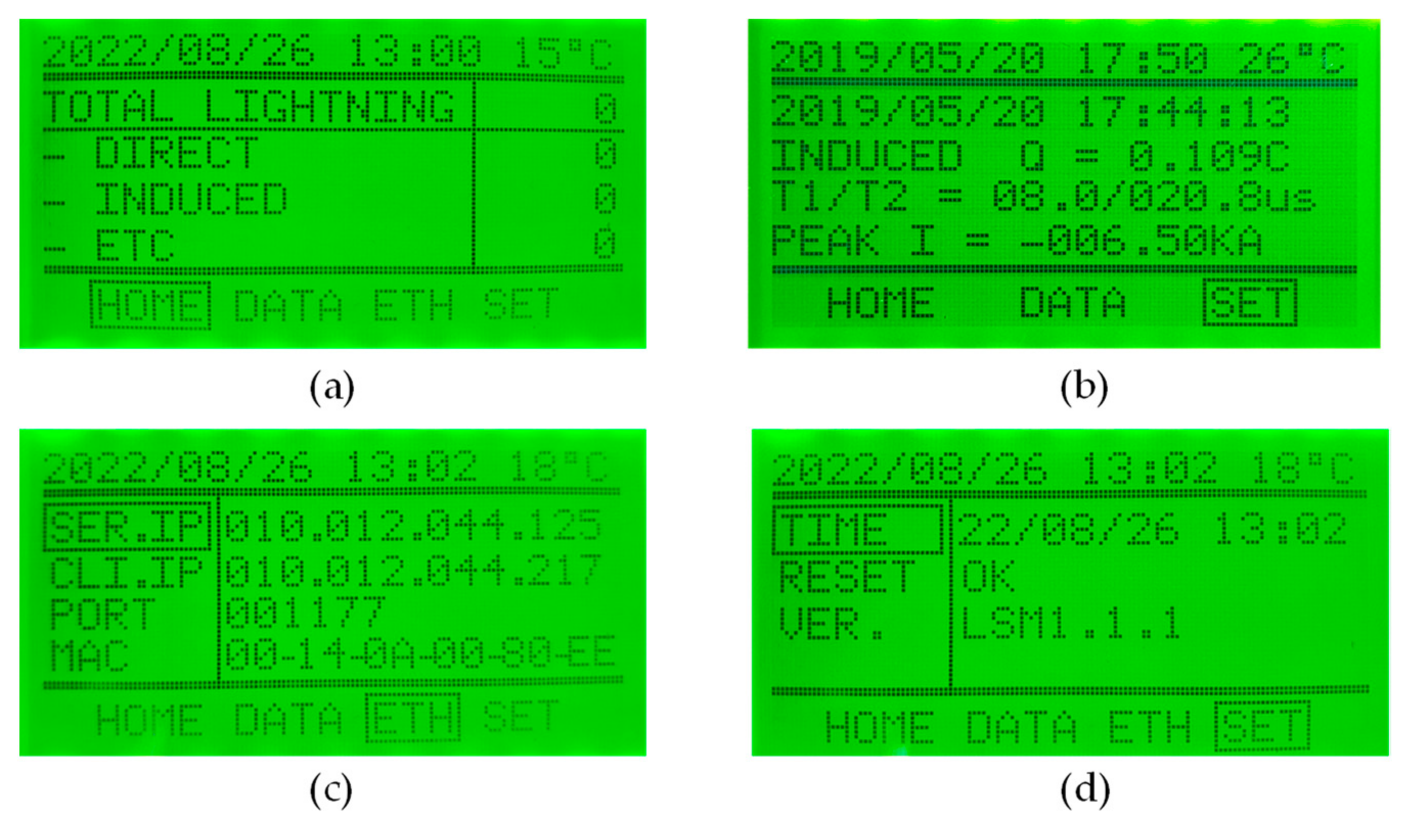
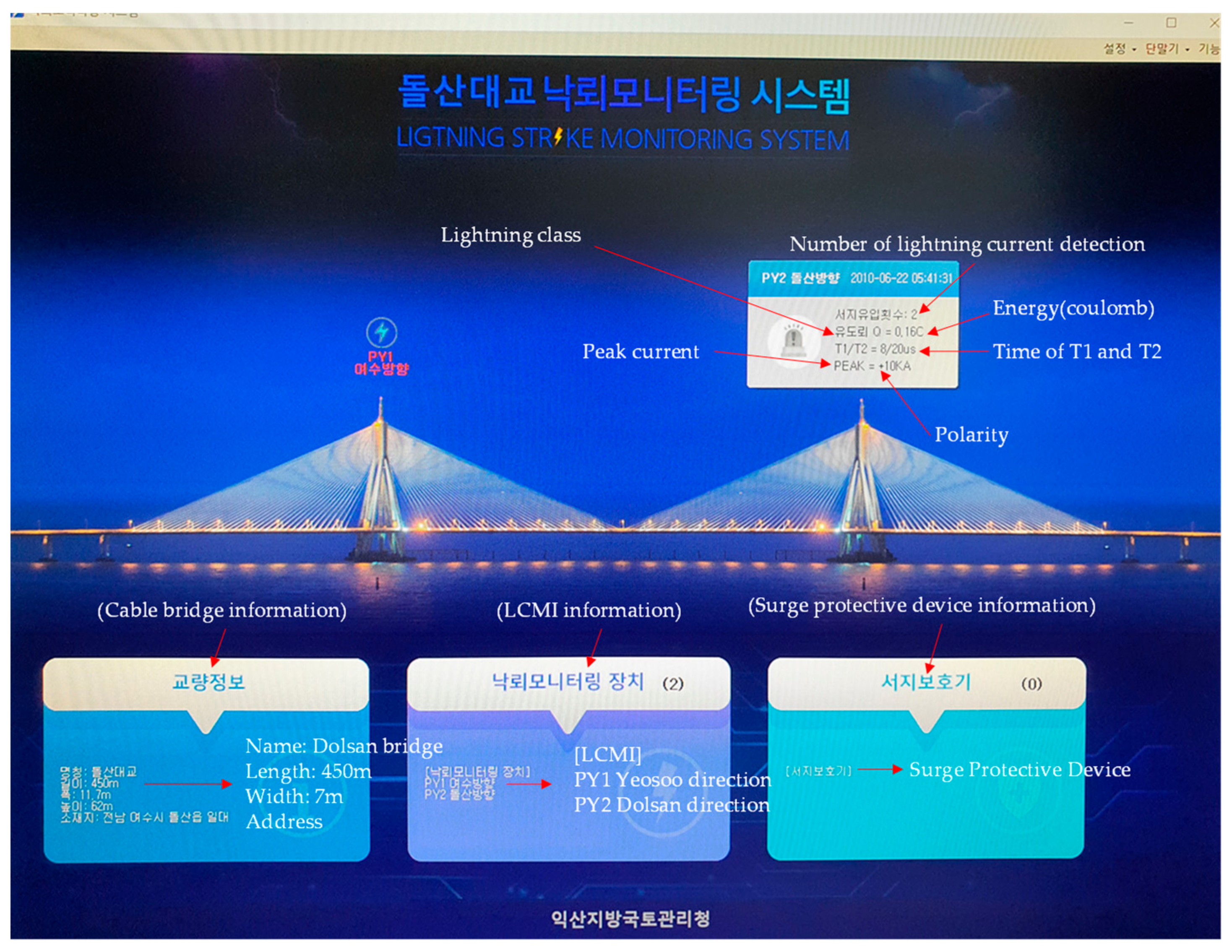
2.7. A Software of the Remote Monitoring
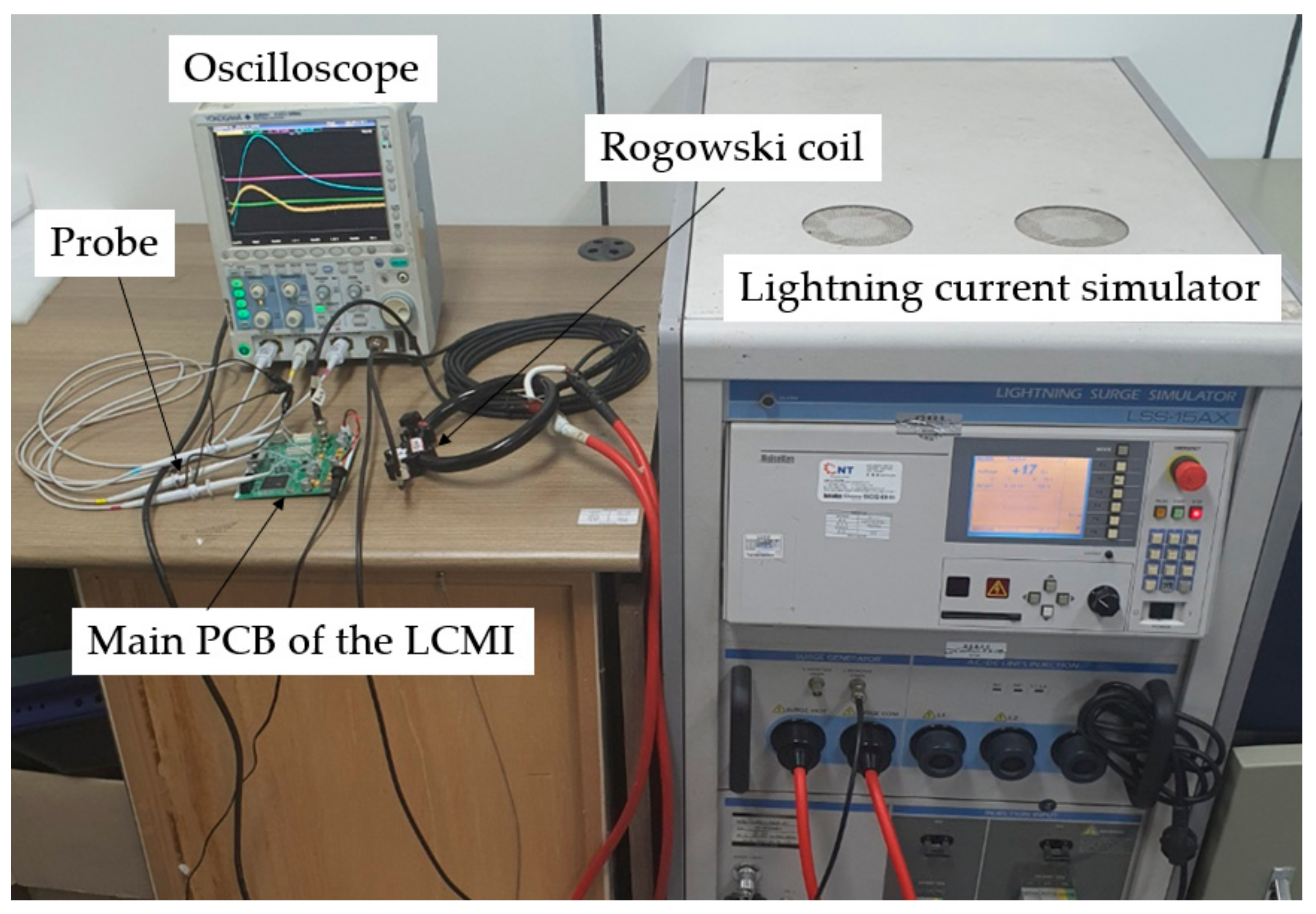
3. Results
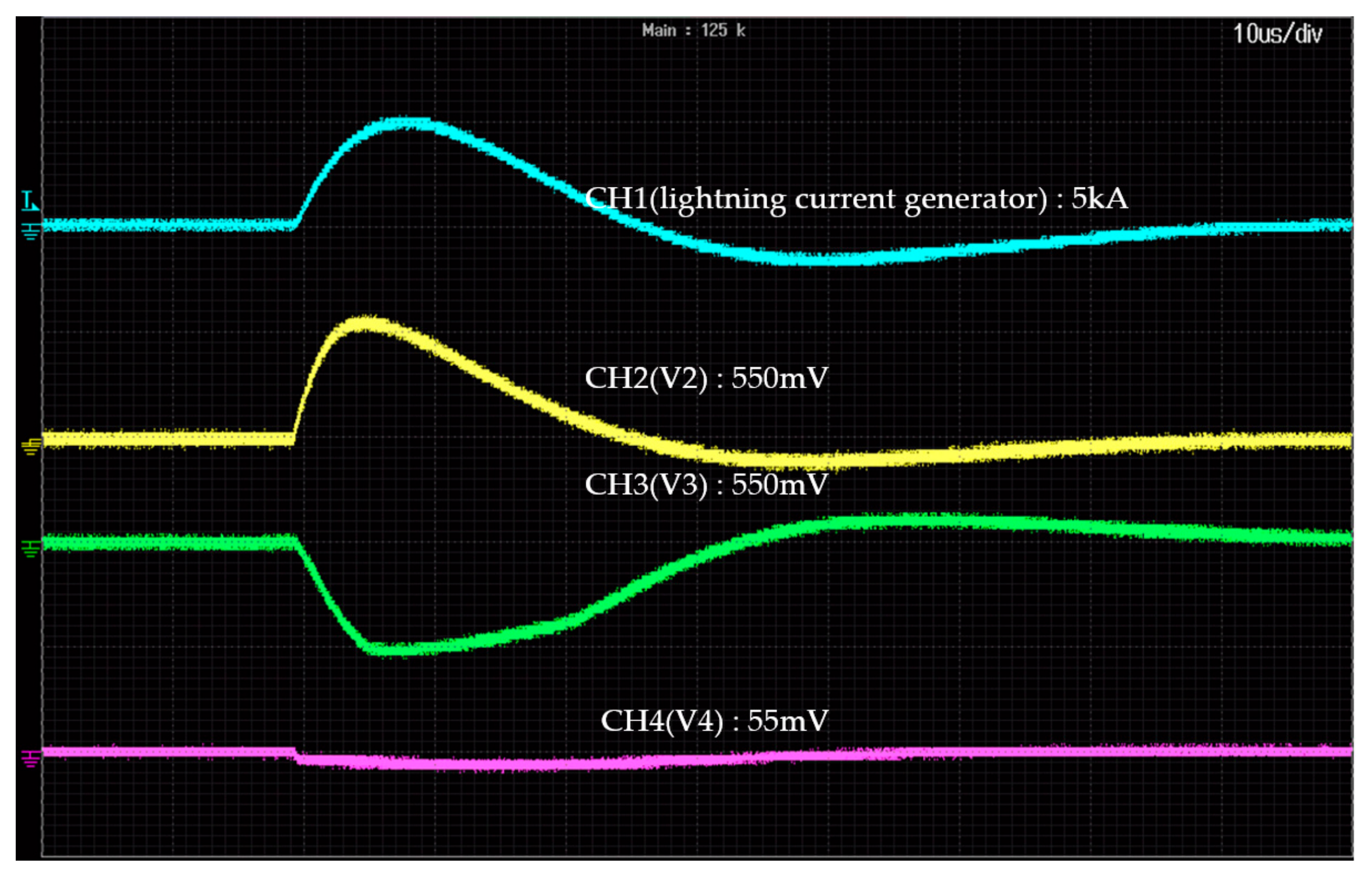
3.1. Test Results of Induced Lightning Current
3.2. Test Results of Direct Lightning Current
4. Discussion
5. Conclusions
Author Contributions
Funding
Data Availability Statement
Acknowledgments
Conflicts of Interest
References
- David, M.R.; Jacob, T.S.; David, V.; John, M. Projected increase in lightning strikes in the United States due to global warming. Science 2014, 346, 851–854. [Google Scholar]
- Colin, P.; David, R. Possible implications of global climate change on global lightning distributions and frequencies. J. Geophys. Res. Atoms. 1994, 99, 10823–10831. [Google Scholar]
- Lightning Report; Weathers Radar Center of Korea Meteorological Administration: Seoul, Republic of Korea, 2021.
- Haddad, A.; Warne, D.F. Advances in High Voltage Engineering, 1st ed.; The Institution of Engineering and Technology: London, UK, 2017; pp. 77–130. [Google Scholar]
- Nur, H.Z.; Mohd, Z.A.A.K.; Mohd, A.M.R.; Mahdi, I.; Norhafiz, A.; Nor, I.A.; Mohd, S.M.N. Lightning surge analysis on a large scale grid-connected solar photovoltaic system. Energies 2017, 10, 2149. [Google Scholar] [CrossRef] [Green Version]
- Andreotti, A.; Mottola, F.; Pierno, A.; Proto, D. On the statistical characterization of lightning-induced voltages. Appl. Sci. 2018, 8, 651. [Google Scholar] [CrossRef] [Green Version]
- Filik, K.; Karnas, G.; Masłowski, G.; Oleksy, M.; Oliwa, R.; Bulanda, K. Testing of Conductive Carbon Fiber Reinforced Polymer Composites Using Current Impulses Simulating Lightning Effects. Energies 2021, 14, 7899. [Google Scholar] [CrossRef]
- IEC 62305-1; Protection against Lightning—Part 1: General Principles. 2010. Available online: https://webstore.iec.ch/preview/info_iec62305-1%7Bed2.0%7Den.pdf (accessed on 27 February 2023).
- IEC 62305-2; Protection against Lightning—Part 2: Rick Management. 2010. Available online: https://webstore.iec.ch/preview/info_iec62305-2%7Bed2.0%7Den.pdf (accessed on 27 February 2023).
- IEC 62305-3; Protection against Lightning—Part 3: Physical Damage to Structures and Life Hazard. 2010. Available online: https://webstore.iec.ch/preview/info_iec62305-3%7Bed2.0%7Den.pdf (accessed on 27 February 2023).
- IEC 60305-4; Protection against Lightning—Part 4: Electrical and Electronic System within Structures. 2010. Available online: https://webstore.iec.ch/preview/info_iec62305-4%7Bed2.0%7Den.pdf (accessed on 27 February 2023).
- Jeoung, T.H.; Kim, Y.S.; Nam, S.P.; Lee, S.H.; Kang, J.W.; Kim, J.C.; Lee, S.G. Development of thermal runaway preventing ZnO varistor for surge protective device. J. Nanosci. Nanotechnol. 2014, 14, 8957–8960. [Google Scholar] [CrossRef] [PubMed]
- Zhou, Q.; Huang, X.; Wei, B.; Ye, L. Impulse life evaluation method of MOV based on Weibull distribution. IEEE Access 2021, 9, 34818–34828. [Google Scholar] [CrossRef]
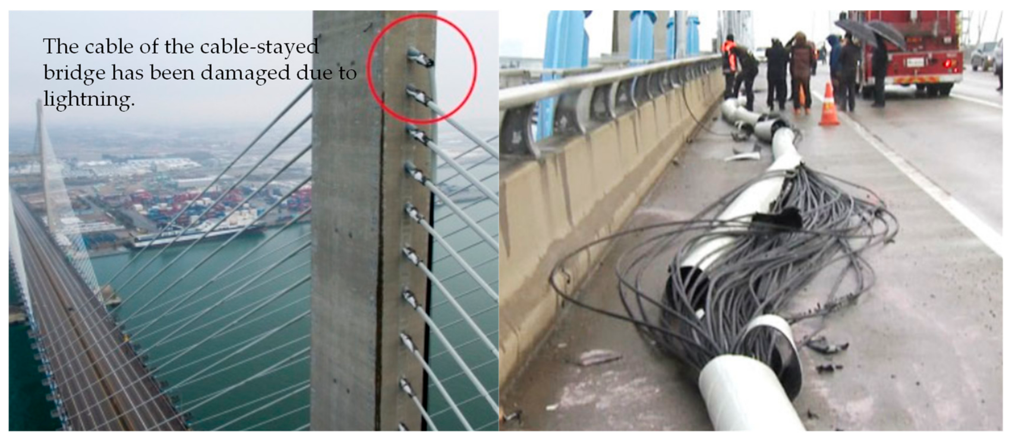
- Kim, M.O.; Kim, K.; Yun, J.H.; Kim, M.K. Fire risk assessment of cable bridges for installation of firefighting facilities. Fire Saf. J. 2020, 115, e103146. [Google Scholar] [CrossRef]
- Zhongjiang, Y.; Tianqi, Y.; Chunxia, N. Hazard analysis and protection measures of direct lightning on Lishui bridge. In Proceedings of the 2011 International Conference on Electrical and Control Engineering, Rzeszow, Poland, 2–7 September 2011; pp. 3485–3488. [Google Scholar]
- Edirisinghe, C.M.; Rupasinghe, D.; Jinadasa, C.P. Design Methods of Lightning Protection Systems by Keeping Aesthetic View of Architecturally Complex Structures. Int. Lett. Chem. Phys. Astron. 2015, 52, 127. [Google Scholar] [CrossRef]
- Tsili, M.; Zacharopoulos, D. Does Temperature Effects to Propagation and Growth of Cracks in a Stay-cable of Cable-Bridge due to Lightining–Strike? Am. J. Mech. Eng. 2017, 5, 151–155. [Google Scholar]
- Hartono, Z.A.; Robiah, I. Lightning protection for the Holy Mosque and the Jamarat Bridge in Makkah. In Proceedings of the 2014 International Conference on Lightning Protection, Shanghai, China, 11–18 October 2014; pp. 1282–1286. [Google Scholar]
- Ge, J.M.; Shen, Y.; Yu, W.B.; Han, Y.; Duan, F.W. Study on the application of optical current sensor for lightning current measurement of transmission line. Sensors 2019, 19, 5110. [Google Scholar] [CrossRef] [Green Version]
- Kawabata, T.; Yanagawa, S.; Takahashi, H.; Yamamoto, K. A development of a shunt lightning current measuring system using a Rogowski coil. In Proceedings of the 2013 International Symposium on Lightning Protection (XII SIPDA), Belo Horizonte, Brazil, 7–11 October 2013; pp. 283–286. [Google Scholar]
- Lee, Y.; Lee, Y.S. A low-cost surge current detection sensor with predictive lifetime display function for maintenance of surge protective devices. Sensors 2020, 20, 2310. [Google Scholar] [CrossRef] [PubMed] [Green Version]
- Datasheet of Rogowski Coil. Available online: http://www.anyparts.co.kr/shop/goods/goods_view.php?&goodsno=1288771226 (accessed on 27 February 2023).
- Kojovic, L. Rogowski coils suit relay protection and measurement~ of power systems. IEEE Comput. Appl. Power 1997, 10, 47–52. [Google Scholar] [CrossRef]
- Hemmati, E.; Shahrtash, S.M. Digital compensation of Rogowski coil’s output voltage. IEEE Trans. Instrum. Meas. 2012, 62, 71–82. [Google Scholar] [CrossRef]
- Datasheet of TMS320F28335. Available online: https://www.ti.com/product/ko-kr/TMS320F28335 (accessed on 27 February 2023).
- Datasheet of ATMEGA1280. Available online: https://www.microchip.com/en-us/product/ATMEGA1280 (accessed on 27 February 2023).
- Datasheet of SAM3X/SAM3A. Available online: https://www.microchip.com/en-us/product/ATSAM3X8E (accessed on 27 February 2023).
- Datasheet of STM32MP157. Available online: https://www.st.com/en/microcontrollers-microprocessors/stm32mp157.html (accessed on 27 February 2023).
- Datasheet of dsPIC33EP. Available online: https://www.microchip.com/en-us/products/microcontrollers-and-microprocessors/dspic-dscs/dspic33e/dspic33ep-gp (accessed on 27 February 2023).


| Features | P Company | I Company |
|---|---|---|
| Size (mm) | 77.6 × 185 × 181.5 | 560 × 560 × 750 |
| sensor | optical lightning sensor | CT (Current transformer) |
| current detection range (kA) | ±5–400 | ±0.5–100 |
| IP class | IP20 | IP43 |
| Internal memory | none | SD card |
| time and date information | yes | yes |
| price (USD) | few thousand | few tens of thousands |
| Lightning Current | (µs) | (µs) |
|---|---|---|
| Direct | 10 | 350 |
| Induced | 8 | 20 |
| Parameter | Values | Type of Strike | ||
|---|---|---|---|---|
| 95% | 50% | 5% | ||
| (C) | 1.1 | 4.5 | 20 | Negative flash |
| 2 | 16 | 150 | Positive flash | |
| Strike duration (µs) | 30 | 75 | 200 | First negative short |
| 25 | 230 | 2000 | First positive short (single) | |
| Part No. | Inner Diameter | Outer Diameter | Height | Current Detection Range | Frequency Range |
|---|---|---|---|---|---|
| FR-450 | 158 mm | 126 mm | 16 mm | 1 A–100 kA | 10 Hz–500 kHz |
| Lightning Current (kA) | ; ADC0 | ; ADC1 | |
|---|---|---|---|
| none | 0 | 1.5 | 1.5 |
| +0.5 | −0.05 | 1.5 − 0.05 | 1.5 − 0.005 |
| −0.5 | −0.05 | 1.5 − 0.05 | 1.5 − 0.005 |
| +10 | +1.0 | 1.5 + 1.0 | 1.5 + 0.1 |
| −10 | −1.0 | 1.5 − 1.0 | 1.5 − 0.1 |
| +15 | +1.5 | 1.5 + 1.5 (signal saturation) | 1.5 + 0.15 |
| −15 | −1.5 | 1.5 − 1.5 (signal saturation) | 1.5 − 0.15 |
| +100 | +10.0 | 1.5 + 10.0 (signal saturation) | 1.5 + 1.0 |
| −100 | −10.0 | 1.5 − 10.0 (signal saturation) | 1.5 − 1.0 |
| Test Equipment | Maker | Model | Specification |
|---|---|---|---|
| Lightning current generator | Noiseken (Kanagawa, Japan) | LSS-15AX | Voc (1.2/50 µs): Isc (8/20 µs): 7.5 kA |
| Oscilloscope | Yokogawa (Tokyo, Japan) | DLM2054 | 2.5 Gs, 500 MHz |
| Scope probe | Yokogawa (Tokyo, Japan) | 701939 | 600 V, 600 MHz |
| Part Name of the Microcontroller | Maker | Maximum Resolution | ADC Sampling Time |
|---|---|---|---|
| TMS320F28335 | Texas Instrument (Dollas, USA) | 12-bits | 380 ns |
| ATMEGA1280 | Microchip (Chandler, USA) | 10-bits | 13–260 μs |
| SAM3X/SAM3A series | Microchip (Chandler, USA) | 12-bits | 1 μs |
| STM32MP157 | STMicroelectronics (Geneva, Switzerland) | 16-bits | 222 ns @ 12-bit |
| dsPIC33EP | Microchip (Chandler, USA) | 12-bits | 910 ns |
| Applied Lightning Current | Test Results | |||||
|---|---|---|---|---|---|---|
| (8/20 µs) | Q (coulomb) | Peak Current | Tolerance (%) | Lightning Class | (µs) | Q (coulomb) |
| +0.25 kA | 0.0047 | Not detected | - | - | - | - |
| −0.25 kA | −0.0047 | Not detected | - | - | - | - |
| +0.5 kA | 0.0095 | +0.53 | 6 | Induced | 7.5/21.1 | 0.011 |
| −0.5 kA | 0.0095 | −0.48 | 4 | Induced | 8.3/20.5 | 0.009 |
| +10.2 kA | 0.1932 | +10.9 | 6.8 | Induced | 7.9/21.2 | 0.209 |
| −9.9 kA | 0.1876 | −9.7 | 2.1 | Induced | 8.7/21.6 | 0.186 |
| +40.5 kA | 0.7674 | +42.5 | 4.9 | Induced | 7.9/21.1 | 0.818 |
| −39.7 kA | 0.7523 | −38.4 | 3.3 | Induced | 7.5/21.3 | 0.739 |
| +81 kA | 1.534 | 87.3 | 7.3 | Induced | 7.4/22.0 | 1.680 |
| −79.2 kA | 1.5 | 72.3 | 8.7 | Induced | 7.9/21.8 | 1.391 |
| Applied Lightning Current | Test Results | |||||
|---|---|---|---|---|---|---|
| (10/350 µs) | Q (coulomb) | Peak Current | Tolerance (%) | Lightning Class | (µs) | Q (coulomb) |
| +54.0 kA | 27.1 | +52.16 kA | 3.4 | Direct | 11.1/342.4 | 26.2 |
| −51.2 kA | 25.7 | −49.77 kA | 2.8 | Direct | 8.5/333.7 | 23.4 |
| +103.2 kA | 51.8 | +113.05 kA | 9.5 | Direct | 10.5/320.2 | 49.3 |
| −104.0 kA | 52.1 | −100.8 kA | 3.1 | Direct | 9.7/310.7 | 48.3 |
| LCMI | Size (mm) | Detection Range (kA) | Sensor | Polarity | Energy | Peak Current | Lightning Class | Cost (USD) |
|---|---|---|---|---|---|---|---|---|
| Proposed LCMI | 140 × 117 × 85.5 | ±0.5–100 | Rogowski coil | O | O | O | O | Few thousand |
| P Company LCMI | 77.6 × 185 × 181.5 | ±5–400 | Fiber optic | O | X | O | X | Few thousand |
| I Company LCMI | 560 × 560 × 750 | ±0.5–100 | CT | O | X | O | X | Few tens of thousands |
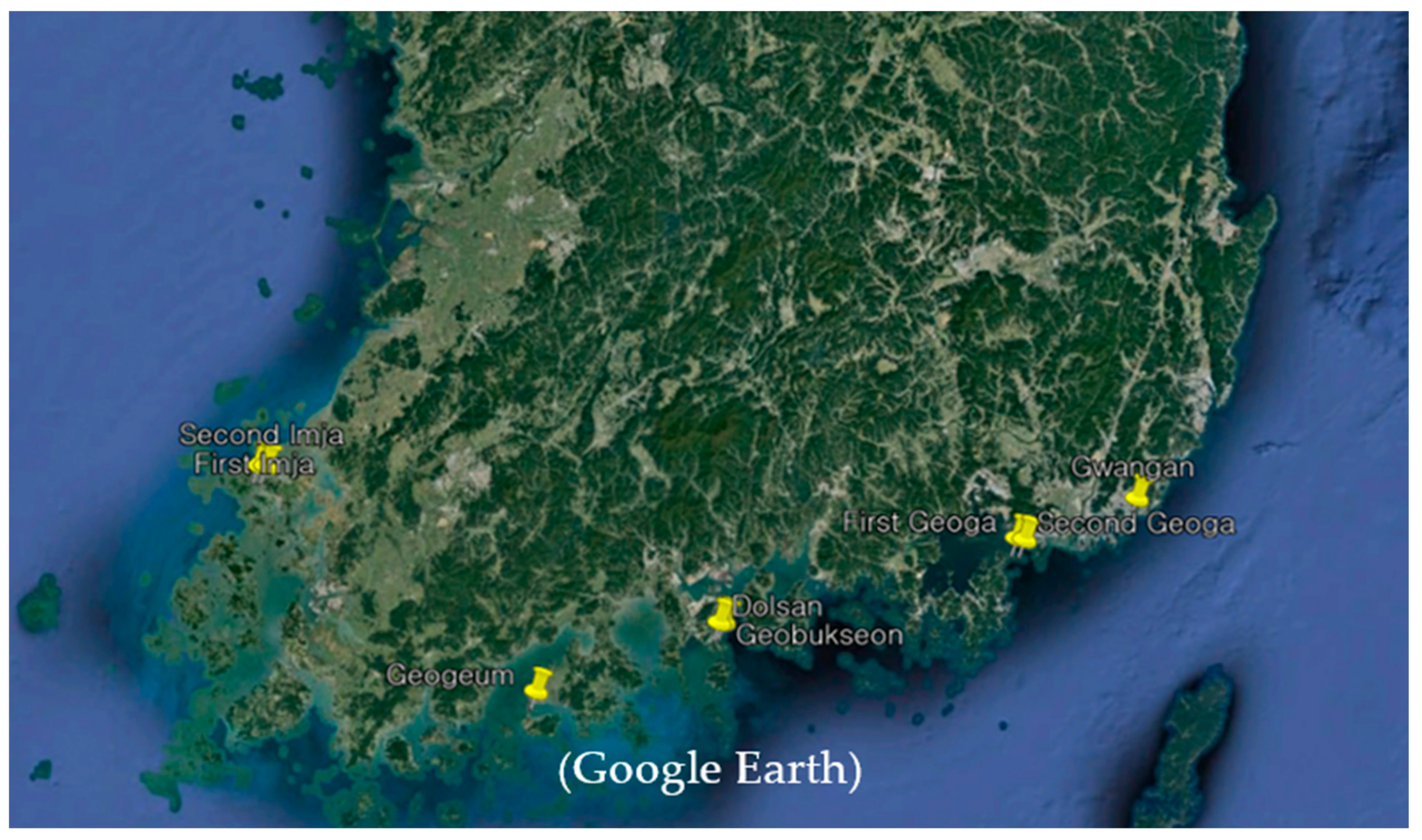
| Name of the Cable Bridges | Location (Latitude, Longitude) | Installation Amount | Year of Installation |
|---|---|---|---|
| Geobukseon | 34.7344° N, 127.7489° E | 2 | 2019 |
| Geogeum | 34.5001° N, 127.1282° E | 2 | 2019 |
| Gwangan | 35.1477° N, 129.1300° E | 2 | 2020 |
| Dolsan | 34.7307° N, 127.7345° E | 2 | 2021 |
| First Imja | 35.0863° N, 126.1259° E | 2 | 2021 |
| Second Imja | 35.0865° N, 126.1517° E | 2 | 2021 |
| First Geoga | 35.0176° N, 128.7288° E | 3 | 2022 |
| Second Geoga | 35.0151° N, 128.7545° E | 2 | 2022 |
Disclaimer/Publisher’s Note: The statements, opinions and data contained in all publications are solely those of the individual author(s) and contributor(s) and not of MDPI and/or the editor(s). MDPI and/or the editor(s) disclaim responsibility for any injury to people or property resulting from any ideas, methods, instructions or products referred to in the content. |
© 2023 by the authors. Licensee MDPI, Basel, Switzerland. This article is an open access article distributed under the terms and conditions of the Creative Commons Attribution (CC BY) license (https://creativecommons.org/licenses/by/4.0/).
Share and Cite
Lee, Y.; Lee, Y.S. A Cost-Effective Lightning Current Measuring Instrument with Wide Current Range Detection Using Dual Signal Conditioning Circuits. Sensors 2023, 23, 3349. https://doi.org/10.3390/s23063349
Lee Y, Lee YS. A Cost-Effective Lightning Current Measuring Instrument with Wide Current Range Detection Using Dual Signal Conditioning Circuits. Sensors. 2023; 23(6):3349. https://doi.org/10.3390/s23063349
Chicago/Turabian StyleLee, Youngjun, and Young Sam Lee. 2023. "A Cost-Effective Lightning Current Measuring Instrument with Wide Current Range Detection Using Dual Signal Conditioning Circuits" Sensors 23, no. 6: 3349. https://doi.org/10.3390/s23063349