
Laser Sensing and Vision Sensing Smart Blind Cane: A Review
 , ,
, ,
Abstract
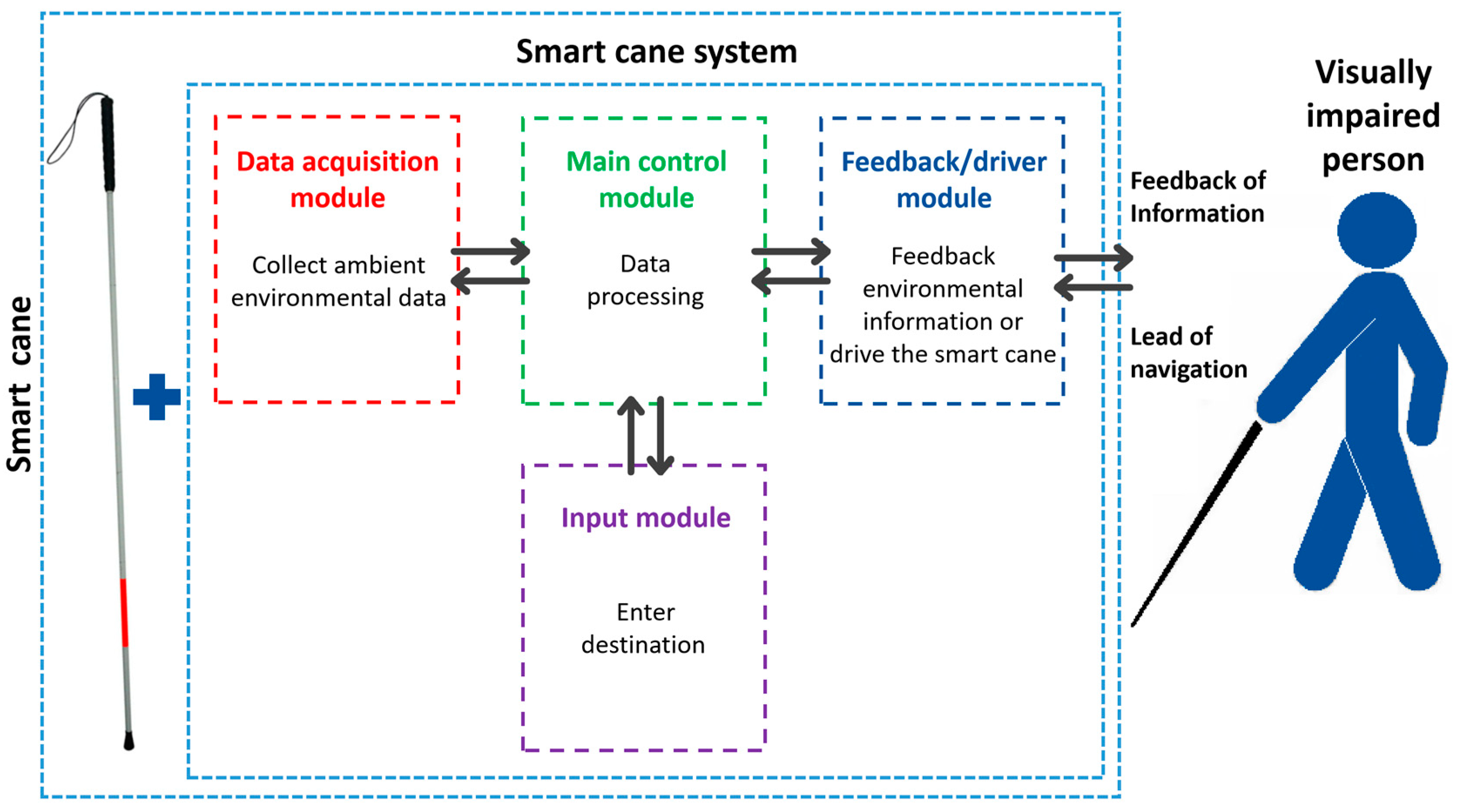
:1. Introduction
2. Application Status of Laser Vision Sensing Smart Cane
2.1. Laser Sensing Smart Cane
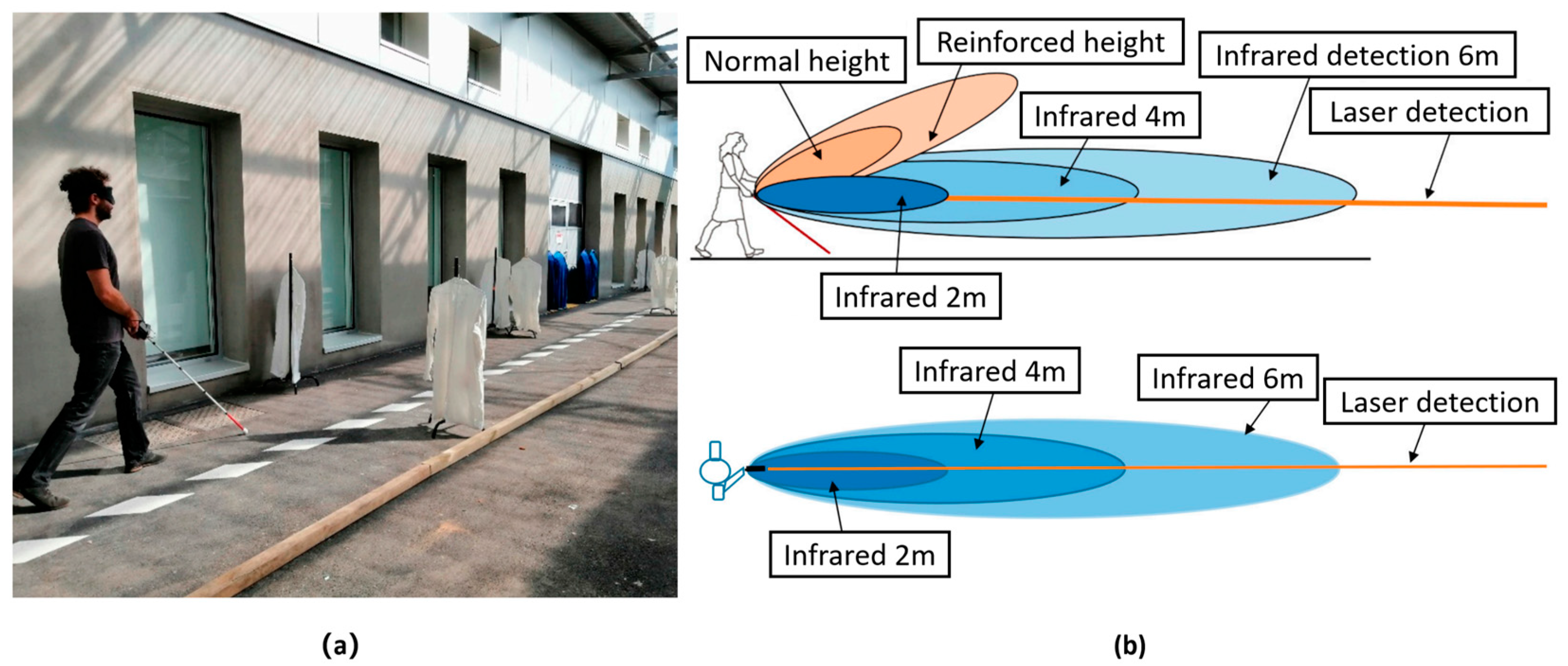
2.1.1. Improvement in the Detection Accuracy and Range of the Laser Smart Canes
2.1.2. Smart Blind Cane Composed of Laser and Other Sensors
2.1.3. Laser SLAM Smart Cane
2.2. Visual Sensing Smart Cane
2.2.1. Visual SLAM Smart Cane
2.2.2. Visual Recognition Smart Cane
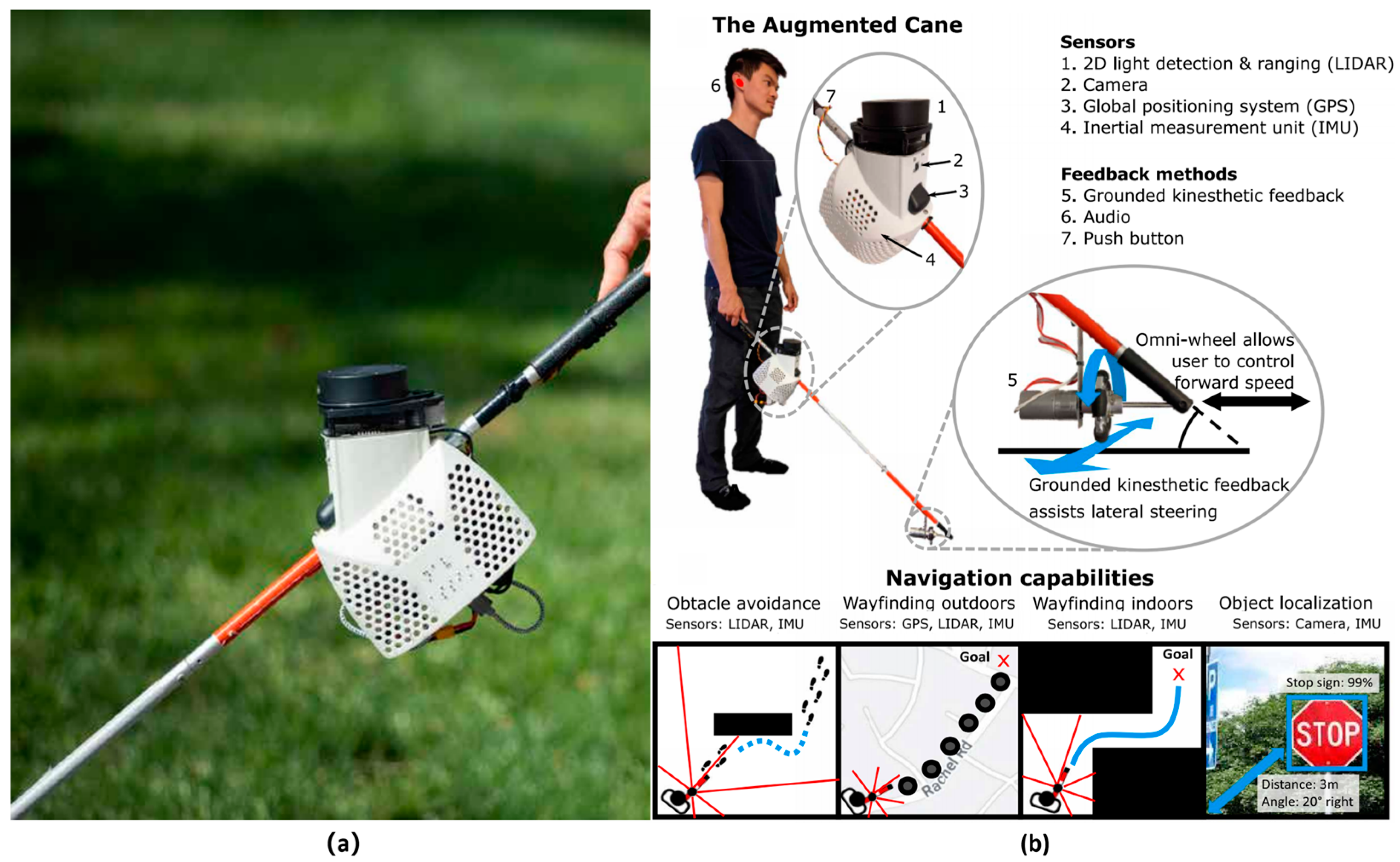
2.2.3. Obstacle Avoidance Smart Cane with Visual Integration with Other Sensors
2.2.4. VR/MR Smart Cane
3. Research Progress of Laser Vision Multi-Sensor Integration Smart Cane
3.1. Laser Vision Integrated Sensor Smart Cane
3.2. Comparative Discussion
3.3. Smart Canes Applying the Laser and Vision Fusion Sensing Technology
3.3.1. Laser and Visual Fusion SLAM
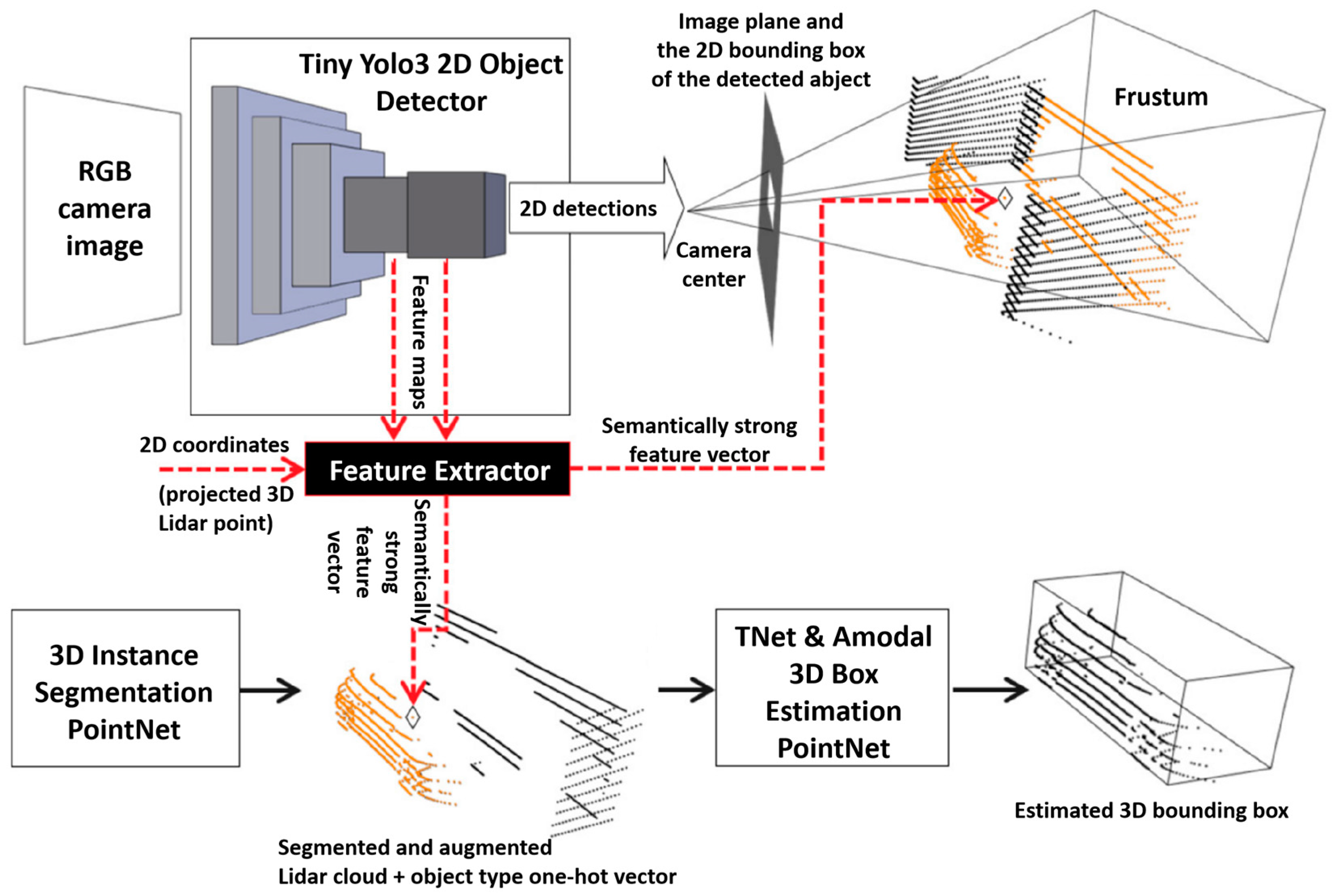
3.3.2. Laser and Vision Fusion Target Detection
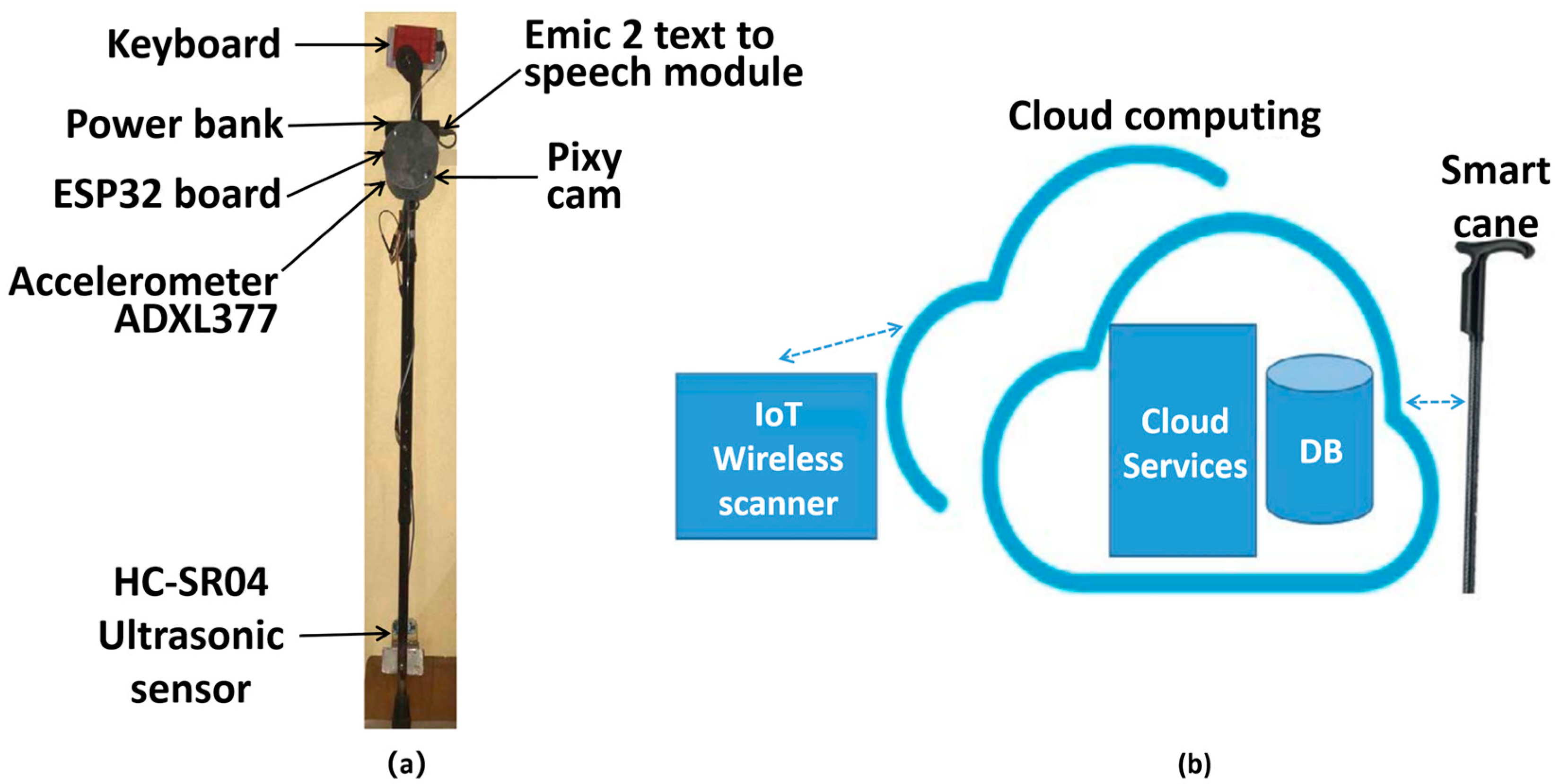
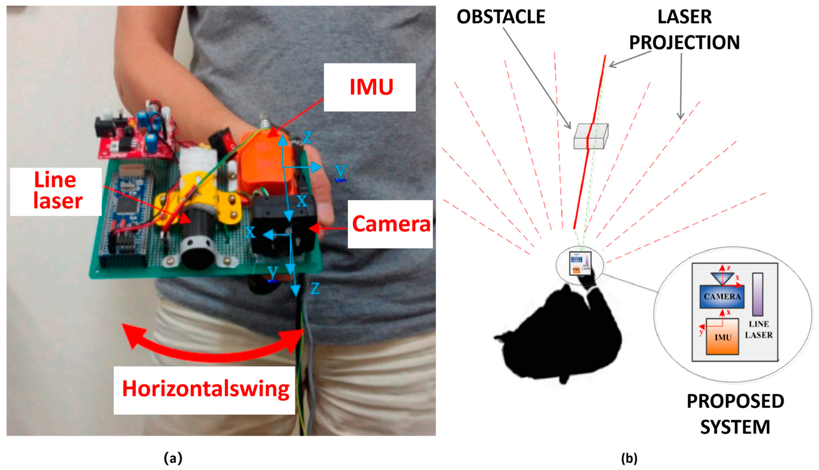
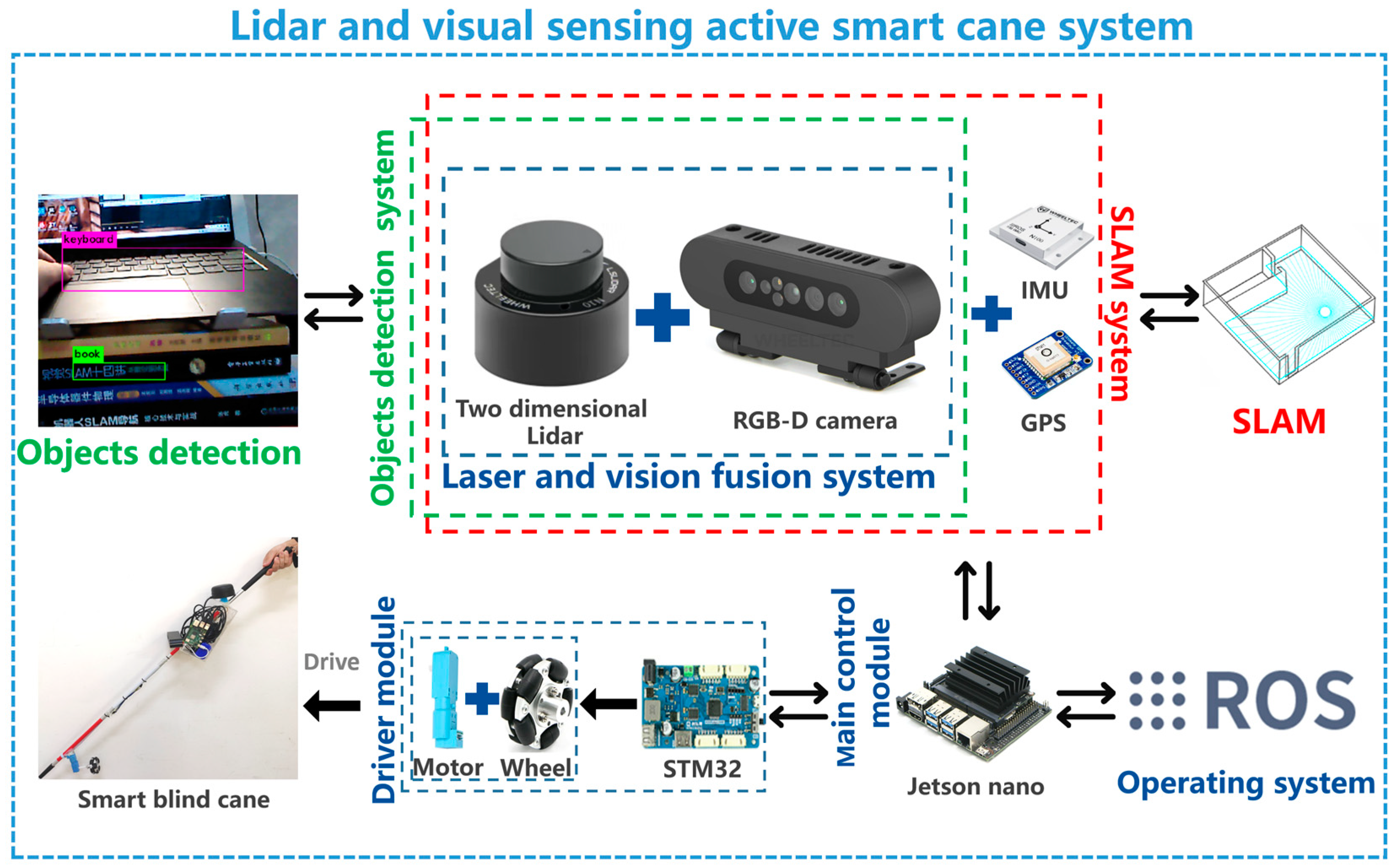
3.3.3. Laser and Vision Fusion Sensor Smart Cane
4. Future Development of Laser Vision Sensing Smart Canes
4.1. Integration and Fusion of Multi-Sensor Smart Canes
4.2. Navigation Modes of Smart Canes
4.3. Smart Cane System Coordinated by IoT
5. Conclusions and Discussion
Author Contributions
Funding
Institutional Review Board Statement
Informed Consent Statement
Data Availability Statement
Conflicts of Interest
References
- World Health Organization. World Report on Vision. Available online: https://www.who.int/zh/news-room/detail/08-10-2019-who-launches-first-world-report-on-vision (accessed on 24 November 2022).
- Ackland, P.; Resnikoff, S.; Bourne, R. World blindness and visual impairment: Despite many successes, the problem is growing. Community Eye Health 2017, 30, 71–73. [Google Scholar]
- Elmannai, W.; Elleithy, K. Sensor-based assistive devices for visually-impaired people: Current status, challenges, and future directions. Sensors 2017, 17, 565. [Google Scholar] [CrossRef] [PubMed] [Green Version]
- Benjamin, J.J. A review of the veterans administration. Bull. Prosthet. Res. 1968, 9, 63. [Google Scholar]
- Kim, L.; Park, S.; Lee, S.; Ha, S. An electronic traveler aid for the blind using multiple range sensors. IEICE Electron. Express 2009, 6, 794–799. [Google Scholar] [CrossRef] [Green Version]
- Kiuru, T.; Metso, M.; Utriainen, M.; Metsävainio, K.; Jauhonen, H.M.; Rajala, R.; Savenius, R.; Ström, M.; Jylhä, T.; Juntunen, R.; et al. Assistive device for orientation and mobility of the visually impaired based on millimeter wave radar technology—Clinical investigation results. Cogent Eng. 2018, 5, 1450322. [Google Scholar] [CrossRef]
- Agarwal, R.; Ladha, N.; Agarwal, M.; Majee, K.K.; Das, A.; Kumar, S.; Rai, S.K.; Singh, A.K.; Nayak, S.; Dey, S.; et al. Low cost ultrasonic smart glasses for blind. In Proceedings of the 2017 8th IEEE Annual Information Technology, Electronics and Mobile Communication Conference (IEMCON), Vancouver, BC, Canada, 3–5 October 2017. [Google Scholar]
- Kassem, K.; Caramazza, P.; Mitchell, K.J.; Miller, M.; Emadi, A.; Faccio, D. Real-time scene monitoring with haptic feedback. Sensors 2022, 22, 7136. [Google Scholar] [CrossRef]
- Schwarze, T.; Lauer, M.; Schwaab, M.; Romanovas, M.; Böhm, S.; Jürgensohn, T. A camera-based mobility aid for visually impaired people. KI-Künstliche Intell. 2016, 30, 29–36. [Google Scholar] [CrossRef] [Green Version]
- Quick, R.; Puente, K.; Bontula, A.; Fitter, N.T. Extending the Depth Perception of People Who Are Blind. In Proceedings of the 2021 IEEE World Haptics Conference (WHC), Montreal, NA, Canada, 6–9 July 2021. [Google Scholar]
- Zvorișteanu, O.; Caraiman, S.; Lupu, R.-G.; Botezatu, N.; Burlacu, A. Sensory substitution for the visually impaired: A study on the usability of the sound of vision system in outdoor environments. Electronics 2021, 10, 1619. [Google Scholar] [CrossRef]
- Siagian, C.; Chang, C.K.; Itti, L. Mobile robot navigation system in outdoor pedestrian environment using vision-based road recognition. In Proceedings of the 2013 IEEE International Conference on Robotics and Automation, Karlsruhe, Germanyon, 6–10 May 2013. [Google Scholar]
- Kayukawa, S.; Sato, D.; Murata, M.; Ishihara, T.; Kosugi, A.; Takagi, H.; Morishima, S.; Asakawa, C. How Users, Facility Managers, and Bystanders Perceive and Accept a Navigation Robot for Visually Impaired People in Public Buildings. In Proceedings of the 2022 31st IEEE International Conference on Robot and Human Interactive Communication (RO-MAN), Napoli, Italy, 29 August–2 September 2022. [Google Scholar]
- Xiao, A.; Tong, W.; Yang, L.; Zeng, J.; Li, Z.; Sreenath, K. Robotic guide dog: Leading a human with leash-guided hybrid physical interaction. In Proceedings of the 2021 IEEE International Conference on Robotics and Automation (ICRA), Xi’an, China, 30 May–5 June 2021. [Google Scholar]
- Huppert, F.; Hoelzl, G.; Kranz, M. GuideCopter-A precise drone-based haptic guidance interface for blind or visually impaired people. In Proceedings of the 2021 CHI Conference on Human Factors in Computing Systems, Yokohama, Japan, 8 May 2021. [Google Scholar]
- Apostolopoulos, I.; Fallah, N.; Folmer, E.; Bekris, K.E. Integrated online localization and navigation for people with visual impairments using smart phones. ACM Trans. Interact. Intell. Syst. 2014, 3, 1–28. [Google Scholar] [CrossRef]
- Lock, J.C.; Cielniak, G.; Bellotto, N. A Portable Navigation System with an Adaptive Multimodal Interface for the Blind. In 2017 AAAI Spring Symposium Series; The AAAI Press: Palo Alto, CA, USA, 2017. [Google Scholar]
- Wahab, A.; Helmy, M.; Talib, A.A.; Kadir, H.A.; Johari, A.; Noraziah, A.; Sidek, R.M.; Mutalib, A.A. Smart cane: Assistive cane for visually-impaired people. Int. J. Comput. Sci. Issues 2011, 8, 4. [Google Scholar]
- Gallo, S.; Chapuis, D.; Santos-Carreras, L.; Kim, Y.; Retornaz, P.; Bleuler, H.; Gassert, R. Augmented white cane with multimodal haptic feedback. In Proceedings of the 2010 3rd IEEE RAS & EMBS International Conference on Biomedical Robotics and Biomechatronics, University of Tokyo, Tokyo, Japan, 26–29 September 2010. [Google Scholar]
- Agrawal, S.; West, M.E.; Hayes, B. A Novel Perceptive Robotic Cane with Haptic Navigation for Enabling Vision-Independent Participation in the Social Dynamics of Seat Choice. In Proceedings of the IEEERSJ International Conference on Intelligent Robots and Systems, Prague, Czech Republic, 27 September–1 October 2021. [Google Scholar]
- Slade, P.; Tambe, A.; Kochenderfer, M.J. Multimodal sensing and intuitive steering assistance improve navigation and mobility for people with impaired vision. Sci. Robot. 2021, 6, eabg6594. [Google Scholar] [CrossRef]
- Farcy, R.; Leroux, R.; Jucha, A.; Damaschini, R.; Grégoire, C.; Zogaghi, A. Electronic travel aids and electronic orientation aids for blind people: Technical, rehabilitation and everyday life points of view. In Proceedings of the Conference & Workshop on Assistive Technologies for People with Vision & Hearing Impairments Technology for Inclusion, Kufstein, Austria, 19–21 July 2006. [Google Scholar]
- Cardillo, E.; Li, C.; Caddemi, A. Empowering blind people mobility: A millimeter-wave radar cane. In Proceedings of the 2020 IEEE International Workshop on Metrology for Industry 4.0 & IoT, Roma, Italy, 3–5 June 2020. [Google Scholar]
- Mocanu, A.; Sita, V.; Avram, C.; Radu, D.; Aştilean, A. Assistive navigation application for blind people using a white cane embedded system. In Proceedings of the 2020 IEEE International Conference on Automation, Quality and Testing, Robotics (AQTR), Cluj-Napoca, Romania, 21–23 May 2020. [Google Scholar]
- Mutiara, G.A.; Hapsari, G.I.; Rijalul, R. Smart guide extension for blind cane. In Proceedings of the 2016 4th International Conference on Information and Communication Technology (ICoICT), Bandung, Indonesia, 25–27 May 2016. [Google Scholar]
- Patil, S.G.; Dennis, D.K.; Pabbaraju, C.; Shaheer, N.; Simhadri, H.V.; Seshadri, V.; Varma, M.; Jain, P. Gesturepod: Enabling on-device gesture-based interaction for white cane users. In Proceedings of the the 32nd Annual ACM Symposium on User Interface Software and Technology, New Orleans, LA, USA, 20–23 October 2019. [Google Scholar]
- Fernandes, H.; Filipe, V.; Costa, P.; Barroso, J. Location based services for the blind supported by RFID technology. Procedia Comput. Sci. 2014, 27, 2–8. [Google Scholar] [CrossRef] [Green Version]
- Brilhault, A.; Kammoun, S.; Gutierrez, O.; Truillet, P.; Jouffrais, C. Fusion of artificial vision and GPS to improve blind pedestrian positioning. In Proceedings of the 4th IFIP International Conference on New Technologies, Mobility and Security (NTMS), Paris, France, 7–10 February 2011; pp. 1–5. [Google Scholar]
- Faria, J.; Lopes, S.; Fernandes, H.; Martins, P.; Barroso, J. Electronic white cane for blind people navigation assistance. In Proceedings of the 2010 World Automation Congress, Kobe, Japan, 19–23 September 2010. [Google Scholar]
- Kim, J. VIVR: Presence of immersive interaction for visual impairment virtual reality. IEEE Access 2020, 8, 196151–196159. [Google Scholar] [CrossRef]
- Pallejà, T.; Tresanchez, M.; Teixidó, M.; Palacin, J. Bioinspired electronic white cane implementation based on a LIDAR, a tri-axial accelerometer and a tactile belt. Sensors 2010, 10, 11322–11339. [Google Scholar] [CrossRef] [Green Version]
- Gomez, J.V.; Sandnes, F.E. RoboGuideDog: Guiding blind users through physical environments with laser range scanners. Procedia Comput. Sci. 2012, 14, 218–225. [Google Scholar] [CrossRef] [Green Version]
- Chai, A.B.C.; Lau, B.T. Exploring the outdoor performance of a LiDAR-based ground plane checking system for the visually impaired. EAI Endorsed Trans. Pervasive Health Technol. 2020, 6, e2. [Google Scholar] [CrossRef]
- Kuribayashi, M.; Kayukawa, S.; Vongkulbhisal, J.; Asakawa, C.; Sato, D.; Takagi, H.; Morishima, S. Corridor-Walker: Mobile indoor walking assistance for blind people to avoid obstacles and recognize intersections. Proc. ACM Hum.-Comput. Interact. 2022, 6, 1–22. [Google Scholar] [CrossRef]
- Bolgiano, D.; Meeks, E. A laser cane for the blind. IEEE J. Quantum Electron. 1967, 3, 268. [Google Scholar] [CrossRef]
- Benjamin, J.J.; Ali, N.A. An Improved Laser Cane for the Blind. In Quantitative Imagery in the Biomedical Sciences II; Proc. SPIE: San Diego, CA, USA, 1973; Volume 40, pp. 101–104. [Google Scholar]
- Dernayka, A.; Amorim, M.A.; Leroux, R.; Bogaert, L.; Farcy, R. Tom Pouce III, an electronic white cane for blind people: Ability to detect obstacles and mobility performances. Sensors 2021, 21, 6854. [Google Scholar] [CrossRef]
- Felix, F.; Swai, R.S.; Dida, M.A.; Sinde, D.R. Development of navigation system for blind people based on light detection and ranging technology (LiDAR). Development 2022, 8, 47–55. [Google Scholar] [CrossRef]
- Hesch, J.A.; Roumeliotis, S.I. Design and analysis of a portable indoor localization aid for the visually impaired. Int. J. Robot. Res. 2010, 29, 1400–1415. [Google Scholar] [CrossRef] [Green Version]
- Tsuboi, Y.; Shimono, T.; Izumi, M.; Takano, Y.; Goshima, O. Detection of Obstacles and Steps by a White Cane Device for Visually Impaired People. In Proceedings of the 2019 IEEE/ASME International Conference on Advanced Intelligent Mechatronics (AIM), Hong Kong, China, 8–12 July 2019. [Google Scholar]
- Alcantarilla, P.F.; Yebes, J.J.; Almazán, J.; Bergasa, L.M. On combining visual SLAM and dense scene flow to increase the robustness of localization and mapping in dynamic environments. In Proceedings of the 2012 IEEE International Conference on Robotics and Automation, Saint Paul, MN, USA, 14–18 May 2012. [Google Scholar]
- Jin, L.; Zhang, H.; Ye, C. Camera intrinsic parameters estimation by visual–inertial odometry for a mobile phone with application to assisted navigation. IEEE/ASME Trans. Mechatron. 2020, 25, 1803–1811. [Google Scholar] [CrossRef]
- Chen, Q.; Khan, M.; Tsangouri, C.; Yang, C.; Li, B.; Xiao, J.; Zhu, Z. CCNY smart cane. In Proceedings of the 2017 IEEE 7th Annual International Conference on CYBER Technology in Automation, Control, and Intelligent Systems (CYBER), Honolulu, HI, USA, 31 July–4 August 2017. [Google Scholar]
- Zhang, H.; Ye, C. An indoor wayfinding system based on geometric features aided graph SLAM for the visually impaired. IEEE Trans. Neural Syst. Rehabil. Eng. 2017, 25, 1592–1604. [Google Scholar] [CrossRef]
- Legge, G.E.; Beckmann, P.J.; Tjan, B.S.; Havet, G.; Kramer, K.; Rolkosky, D.; Gage, R.; Chen, M.; Puchakayala, S.; Rangarajan, A. Indoor navigation by people with visual impairment using a digital sign system. PloS ONE 2013, 8, e76783. [Google Scholar] [CrossRef] [PubMed]
- Ye, C.; Hong, S.; Qian, X. A co-robotic cane for blind navigation. In Proceedings of the 2014 IEEE International Conference on Systems, Man, and Cybernetics (SMC), San Diego, CA, USA, 5–8 October 2014. [Google Scholar]
- Takizawa, H.; Yamaguchi, S.; Aoyagi, M.; Ezaki, N.; Mizuno, S. Kinect cane: An assistive system for the visually impaired based on the concept of object recognition aid. Pers. Ubiquitous Comput. 2015, 19, 955–965. [Google Scholar] [CrossRef]
- Carranza, A.; Baez, A.; Hernandez, J.; Carranza, H.; Rahemi, H. Raspberry Pi and White Cane Integration for Assisting the Visually Impaired. In Proceedings of the the 9th International Conference of Control Systems, and Robotics (CDSR’22), Niagara Falls, NA, Canada, 2–4 June 2022. [Google Scholar]
- Taylor, E.J. An Obstacle Avoidance System for the Visually Impaired Using 3-D Point Cloud Processing. Master’s Thesis, Brigham Young University, Provo, UT, USA, 2017. [Google Scholar]
- Chuang, T.K.; Lin, N.C.; Chen, J.S.; Hung, C.H.; Huang, Y.W.; Teng, C.; Huang, H.; Yu, L.F.; Giarré, L.; Wang, H.C. Deep trail-following robotic guide dog in pedestrian environments for people who are blind and visually impaired-learning from virtual and real worlds. In Proceedings of the 2018 IEEE International Conference on Robotics and Automation (ICRA), Brisbane, QLD, Australia, 21–25 May 2018. [Google Scholar]
- Jin, Y.; Kim, J.; Kim, B.; Mallipeddi, R.; Lee, M. Smart cane: Face recognition system for blind. In Proceedings of the 3rd International Conference on Human-Agent Interaction, Daegu, Republic of Korea, 21–24 October 2015. [Google Scholar]
- Fan, M.Y.; Bao, J.T.; Tang, H.R. A guide cane system for assisting the blind in travelling in outdoor environments. Appl. Mech. Mater. 2014, 631–632, 568–571. [Google Scholar] [CrossRef]
- Li, B.; Munoz, J.P.; Rong, X.; Chen, Q.; Xiao, J.; Tian, Y.; Arditi, A.; Yousuf, M. Vision-based mobile indoor assistive navigation aid for blind people. IEEE Trans. Mob. Comput. 2019, 18, 702–714. [Google Scholar] [CrossRef]
- Zhang, H.; Ye, C. Human-robot interaction for assisted wayfinding of a robotic navigation aid for the blind. In Proceedings of the 2019 12th International Conference on Human System Interaction (HSI), Richmond, VA, USA, 25–27 June 2019. [Google Scholar]
- Messaoudi, M.D.; Menelas, B.A.J.; Mcheick, H. Autonomous smart white cane navigation system for indoor usage. Technologies 2020, 8, 37. [Google Scholar] [CrossRef]
- Tzovaras, D.; Moustakas, K.; Nikolakis, G.; Strintzis, M.G. Interactive mixed reality white cane simulation for the training of the blind and the visually impaired. Pers. Ubiquitous Comput. 2009, 13, 51–58. [Google Scholar] [CrossRef]
- Zhang, L.; Wu, K.; Yang, B.; Tang, H.; Zhu, Z. Exploring virtual environments by visually impaired using a mixed reality cane without visual feedback. In Proceedings of the 2020 IEEE International Symposium on Mixed and Augmented Reality Adjunct (ISMAR-Adjunct), Recife, Brazil, 9–13 November 2020. [Google Scholar]
- Lee, Y.H.; Medioni, G. Wearable RGBD indoor navigation system for the blind. In Proceedings of the European Conference on Computer Vision(ECCV2014), Zurich, Switzerland, 6–12 September 2014. [Google Scholar]
- Mocanu, B.; Tapu, R.; Zaharia, T. When ultrasonic sensors and computer vision join forces for efficient obstacle detection and recognition. Sensors 2016, 16, 1807. [Google Scholar] [CrossRef] [Green Version]
- Rizzo, J.R.; Pan, Y.; Hudson, T.; Wong, E.k.; Fang, Y. Sensor fusion for ecologically valid obstacle identification: Building a comprehensive assistive technology platform for the visually impaired. In Proceedings of the 2017 7th International Conference on Modeling, Simulation, and Applied Optimization (ICMSAO), Sharjah, United Arab Emirates, 4–6 April 2017. [Google Scholar]
- Long, N.; Wang, K.; Cheng, R.; Hu, W.; Yang, K. Unifying obstacle detection, recognition, and fusion based on millimeter wave radar and RGB-depth sensors for the visually impaired. Rev. Sci. Instrum. 2019, 90, 044102. [Google Scholar] [CrossRef] [PubMed]
- Ienaga, T.; Sugimura, Y.; Kimuro, Y.; Wada, C. Pedestrian navigation system using tone gradient and robotic GIS. In Proceedings of the 2010 12th International Conference on Computers for Handicapped Persons(ICCHP), Vienna, Austria, 14–16 July 2010. [Google Scholar]
- Galatas, G.; McMurrough, C.; Mariottini, G.L.; Makedon, F. Eyedog: An assistive-guide robot for the visually impaired. In Proceedings of the 4th international conference on pervasive technologies related to assistive environments, Heraklion, Greece, 25–27 May 2011. [Google Scholar]
- Guerreiro, J.; Sato, D.; Asakawa, S.; Dong, H.; Kitani, K.M.; Asakawa, C. Cabot: Designing and evaluating an autonomous navigation robot for blind people. In Proceedings of the The 21st International ACM SIGACCESS conference on computers and accessibility, Pittsburgh, PA, USA, 28–30 October 2019. [Google Scholar]
- Kayukawa, S.; Higuchi, K.; Guerreiro, J.; Morishima, S.; Sato, Y.; Kitani, K.; Asakawa, C. BBeep: A sonic collision avoidance system for blind travellers and nearby pedestrians. In Proceedings of the the 2019 CHI Conference on Human Factors in Computing Systems, Glasgow, UK, 4–9 May 2019. [Google Scholar]
- Vera, P.; Zenteno, D.; Salas, J. A smartphone-based virtual white cane. Pattern Anal. Appl. 2014, 17, 623–632. [Google Scholar] [CrossRef]
- Saffoury, R.; Blank, P.; Sessner, J.; Groh, B.H.; Martindale, C.F.; Dorschky, E.; Franke, J.; Eskofier, B.M. Blind path obstacle detector using smartphone camera and line laser emitter. In Proceedings of the 2016 1st International Conference on Technology and Innovation in Sports, Health and Wellbeing (TISHW), Vila Real, Portugal, 1–3 December 2016. [Google Scholar]
- Mekhalfi, M.L.; Melgani, F.; Bazi, Y.; Alajlan, N. Fast indoor scene description for blind people with multiresolution random projections. J. Vis. Commun. Image Represent. 2017, 44, 95–105. [Google Scholar] [CrossRef]
- Chitra, P.; Balamurugan, V.; Sumathi, M.; Mathan, N.; Srilatha, K.; Narmadha, R. Voice Navigation Based guiding Device for Visually Impaired People. In Proceedings of the 2021 International Conference on Artificial Intelligence and Smart Systems (ICAIS), Coimbatore, India, 25–27 March 2021. [Google Scholar]
- Kutila, M.; Pyykönen, P.; Holzhüter, H.; Colomb, M.; Duthon, P. Automotive LiDAR performance verification in fog and rain. In Proceedings of the 2018 21st International Conference on Intelligent Transportation Systems (ITSC), Maui, HI, USA, 4–7 November 2018. [Google Scholar]
- Forster, C.; Zhang, Z.; Gassner, M.; Werlberger, M.; Scaramuzza, D. SVO: Semidirect visual odometry for monocular and multicamera systems. IEEE Trans. Robot. 2016, 33, 249–265. [Google Scholar] [CrossRef] [Green Version]
- Fan, K.; Lyu, C.; Liu, Y.; Zhou, W.; Jiang, X.; Li, P.; Chen, H. Hardware implementation of a virtual blind cane on FPGA. In Proceedings of the 2017 IEEE International Conference on Real-time Computing and Robotics (RCAR), Okinawa, Japan, 14–18 July 2017. [Google Scholar]
- Rahman, A.; Malia, K.F.N.; Mia, M.M.; Shuvo, A.M.H.; Nahid, M.H.; Zayeem, A.M. An Efficient Smart Cane Based Navigation System for Visually Impaired People. In Proceedings of the 2019 International Symposium on Advanced Electrical and Communication Technologies (ISAECT), Rome, Italy, 27–29 November 2019. [Google Scholar]
- Dang, Q.K.; Chee, Y.; Pham, D.D.; Suh, Y.S. A virtual blind cane using a line laser-based vision system and an inertial measurement unit. Sensors 2016, 16, 95. [Google Scholar] [CrossRef] [Green Version]
- Foucault, J.; Lesecq, S.; Dudnik, G.; Correvon, M.; O’Keeffffe, R.; Palma, V.D.; Passoni, M.; Quaglia, F.; Ouvry, L.; Buckley, S.; et al. INSPEX: Optimize range sensors for environment perception as a portable system. Sensors 2019, 19, 4350. [Google Scholar] [CrossRef] [Green Version]
- Alsadik, B.; Karam, S. The simultaneous localization and mapping (SLAM)-An overview. Surv. Geospat. Eng. J 2021, 2, 34–45. [Google Scholar]
- Zhang, J.; Singh, S. Visual-lidar odometry and mapping: Low-drift, robust, and fast. In Proceedings of the 2015 IEEE International Conference on Robotics and Automation (ICRA), Seattle, WA, USA, 26–30 May 2015. [Google Scholar]
- Shao, W.; Vijayarangan, S.; Li, C.; Kantor, G. Stereo visual inertial lidar simultaneous localization and mapping. In Proceedings of the 2019 IEEE/RSJ International Conference on Intelligent Robots and Systems (IROS), Macau, China, 3–8 November 2019. [Google Scholar]
- Zuo, X.; Geneva, P.; Lee, W.; Liu, Y.; Huang, G. Lic-fusion: Lidar-inertial-camera odometry. In Proceedings of the 2019 IEEE/RSJ International Conference on Intelligent Robots and Systems (IROS), Macau, China, 3–8 November 2019. [Google Scholar]
- Rövid, A.; Remeli, V.; Szalay, Z. Raw fusion of camera and sparse LiDAR for detecting distant ojects. Automatisierungstechnik 2020, 68, 337–346. [Google Scholar] [CrossRef]
- Mingchi, F.; Xiaoqian, G.; Huizong, F.; Bowang, S. Research on the Fusion Method for Vehicle Shape-position Based on Binocular Camera and Lidar. In Proceedings of the 2021 6th International Symposium on Computer and Information Processing Technology (ISCIPT), Changsha, China, 11–13 June 2021. [Google Scholar]
- Aigner, P.; Mccarragher, B.J. Shared control framework applied to a robotic aid for the blind. IEEE Control Syst. 1999, 19, 40–46. [Google Scholar]
- Ghani, F.A.; Zariman, A. Smart cane based on IoT. Int. J. Educ. Sci. Technol. Eng. 2019, 2, 12–18. [Google Scholar] [CrossRef]
- Pinquart, M.; Pfeiffer, J.P. Psychological well-being in visually impaired and unimpaired individuals: A meta-analysis. Br. J. Vis. Impair. 2011, 29, 27–45. [Google Scholar] [CrossRef]
- Qiao, G.; Zhang, J.; Pabel, A.; Chen, N. Understanding the factors influencing the leisure tourism behavior of visually impaired travelers: An empirical study in China. Front. Psychol. 2021, 12, 2248. [Google Scholar] [CrossRef] [PubMed]


| Type | Sensor | Advantages | Disadvantages | References |
|---|---|---|---|---|
| Laser ranging | Laser rangefinder, laser scanner | High ranging accuracy | Unable to measure surrounding obstacle distance | [22] |
| Lidar ranging | Lidar | Measure the distance of obstacles around | High price, low endurance | [37,38] |
| Virtual | laser scanner | Light weight, flexible to use | Cannot be used in difficult road conditions | [31] |
| Integrated sensor | Laser Scanner + IMU | Obtain attitude information | (1) Loose coupling (2) Large volume (3) Relatively heavy | [39] |
| Laser rangefinder + ultrasonic | Increase range | [40] | ||
| Laser SLAM | Lidar | Map navigation | Cumulative map error | [21] |
| Type | Advantages | Disadvantages | References |
|---|---|---|---|
| Visual SLAM | Path planning | (1) Need prior maps (2) No obstacle recognition function (3) Unable to measure distance | [20,41,42,43,44] |
| Visual recognition | Identify obstacles | (1) Unable path planning (2) Unable to measure distance | [45,46,47,48,49,50,51] |
| Integrated sensor | Get more performance | Loose coupling | [28,52,53,54,55] |
| VR/MR | Perceive the outside world | (1) Immature technology (2) Unable to measure distance | [30,56,57] |
| Type | Advantages | Disadvantages | References |
|---|---|---|---|
| Laser sensing | Measuring distance | Non-recognition function | [37] |
| Visual sensing | Recognition function | No distance measurement function | [47] |
| Integrated laser and visual sensing | Measuring distance and recognition function | Sensor loose coupling | [75] |
| Laser and visual fusion sensing | (1) Measuring distance and recognition function (2) Sensor tight coupling | Immature technology | [74] |
| Mode of Navigation | Advantages | Disadvantages | References |
|---|---|---|---|
| Active navigation | (1) Lead of navigation (2) Fast response speed | (1) High performance requirements for CPU and sensor (2) High power consumption | Omnidirectional wheel [21], Robot car [82] |
| Passive navigation | Feedback environmental information | No navigational lead | Tactile [43], vibration [36], speech [44], sound [40] |
Disclaimer/Publisher’s Note: The statements, opinions and data contained in all publications are solely those of the individual author(s) and contributor(s) and not of MDPI and/or the editor(s). MDPI and/or the editor(s) disclaim responsibility for any injury to people or property resulting from any ideas, methods, instructions or products referred to in the content. |
© 2023 by the authors. Licensee MDPI, Basel, Switzerland. This article is an open access article distributed under the terms and conditions of the Creative Commons Attribution (CC BY) license (https://creativecommons.org/licenses/by/4.0/).
Share and Cite
Mai, C.; Xie, D.; Zeng, L.; Li, Z.; Li, Z.; Qiao, Z.; Qu, Y.; Liu, G.; Li, L. Laser Sensing and Vision Sensing Smart Blind Cane: A Review. Sensors 2023, 23, 869. https://doi.org/10.3390/s23020869
Mai C, Xie D, Zeng L, Li Z, Li Z, Qiao Z, Qu Y, Liu G, Li L. Laser Sensing and Vision Sensing Smart Blind Cane: A Review. Sensors. 2023; 23(2):869. https://doi.org/10.3390/s23020869
Chicago/Turabian StyleMai, Chunming, Dongliang Xie, Lina Zeng, Zaijin Li, Zhibo Li, Zhongliang Qiao, Yi Qu, Guojun Liu, and Lin Li. 2023. "Laser Sensing and Vision Sensing Smart Blind Cane: A Review" Sensors 23, no. 2: 869. https://doi.org/10.3390/s23020869