


A Minimalist Self-Localization Approach for Swarm Robots Based on Active Beacon in Indoor Environments
Abstract
:1. Introduction
1.1. Related Works
1.2. Motivation and Contributions
- (1)
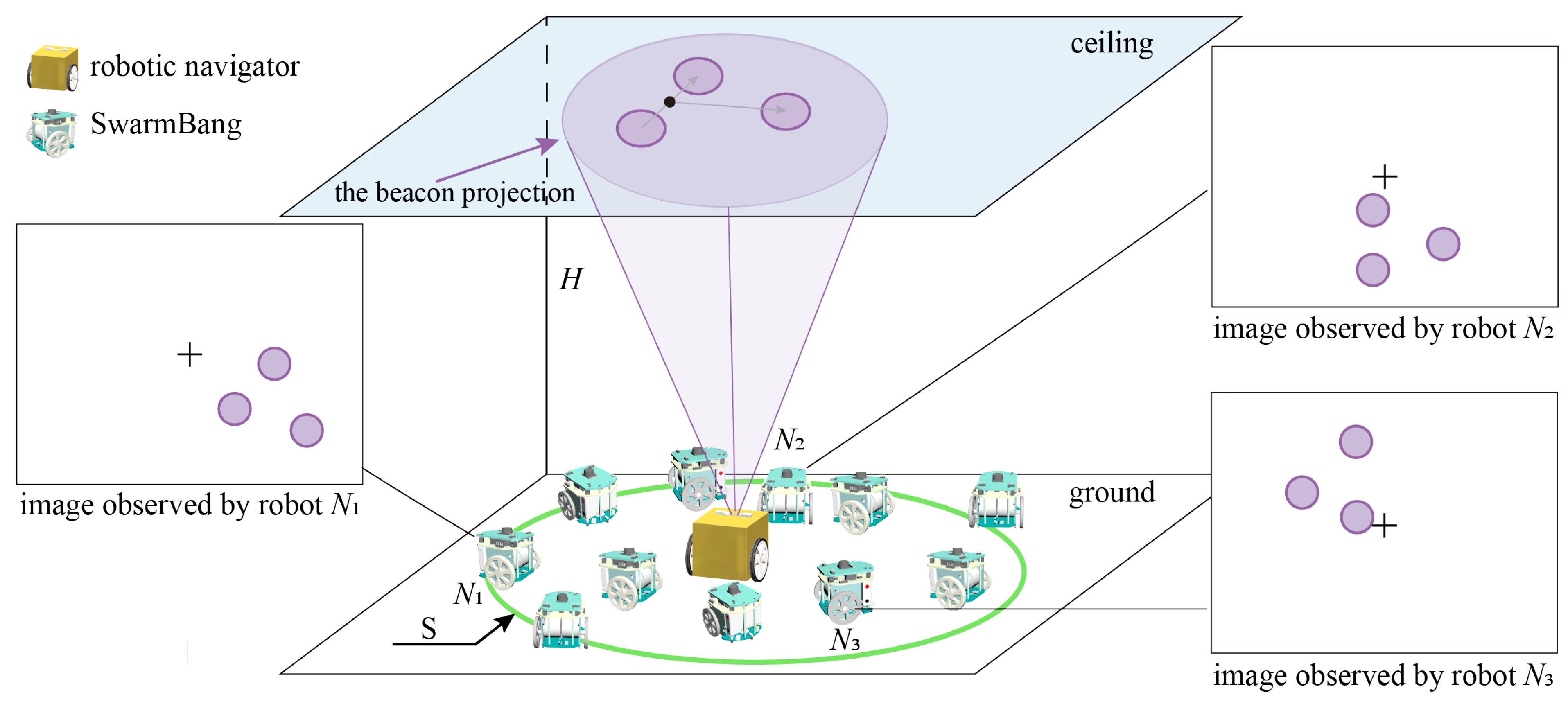
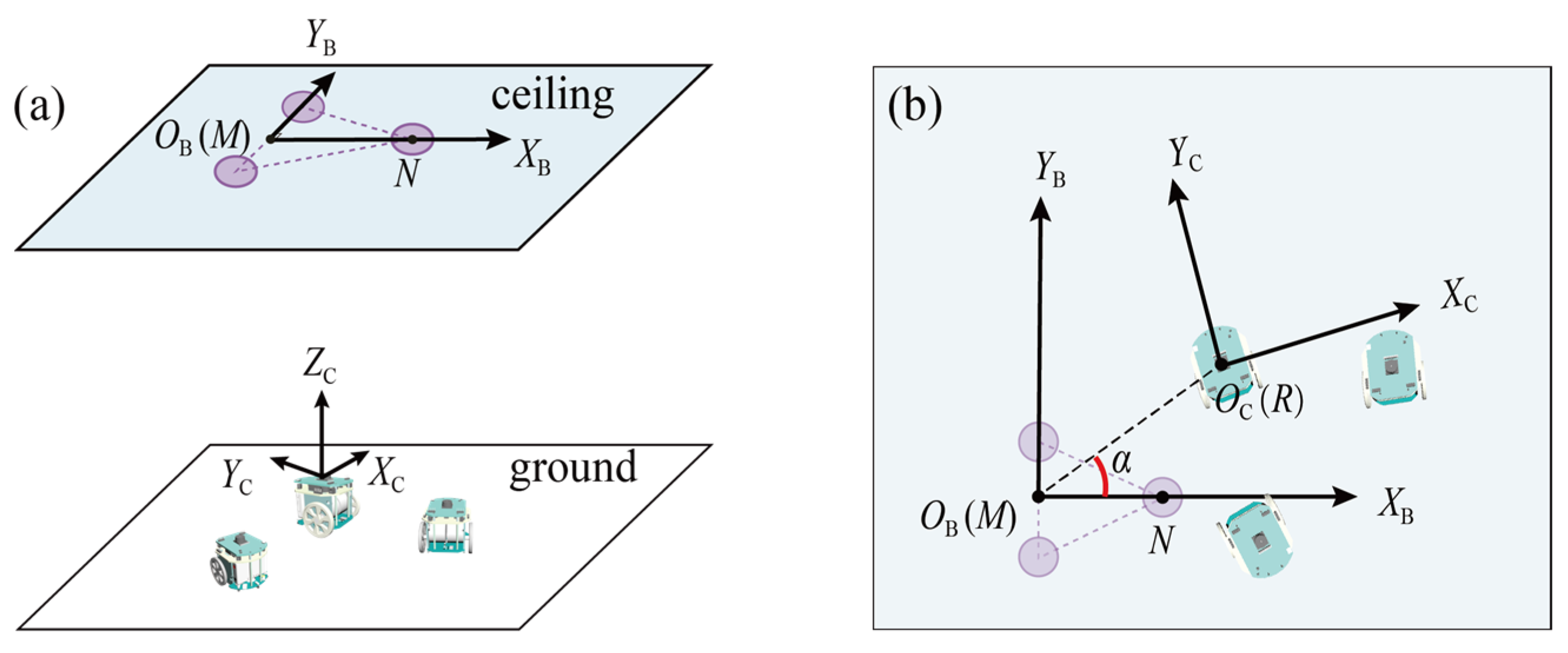
- A cooperative localization approach for indoor swarm robots is proposed, in which a robotic navigator is introduced to project an optical beacon on the building’s ceiling, and swarm robots locate their positions by observing the beacon. The advantages of this approach are considered to be minimalist, and efficient, and with no requirement for auxiliary equipment.
- (2)
- Our unique ceiling-projected beacon and bottom-up visual observation have two main advantages. On the one hand, relative localization failures caused by mutual visual occlusion can be successfully avoided. On the other hand, recognition complexity caused by dynamic environments such as people’s movement and unstructured furniture can be eliminated. In this sense, our approach is suitable for large and dense groups of swarm robots working indoors.
- (3)
- The proposed approach is verified through self-localization experiments using the real robot, and its localization precision is sufficient for the cooperative operation of swarm robots.
1.3. Structure of the Article
2. Localization Approach for Swarm Robots
3. Implementation of Self-Localization Approach
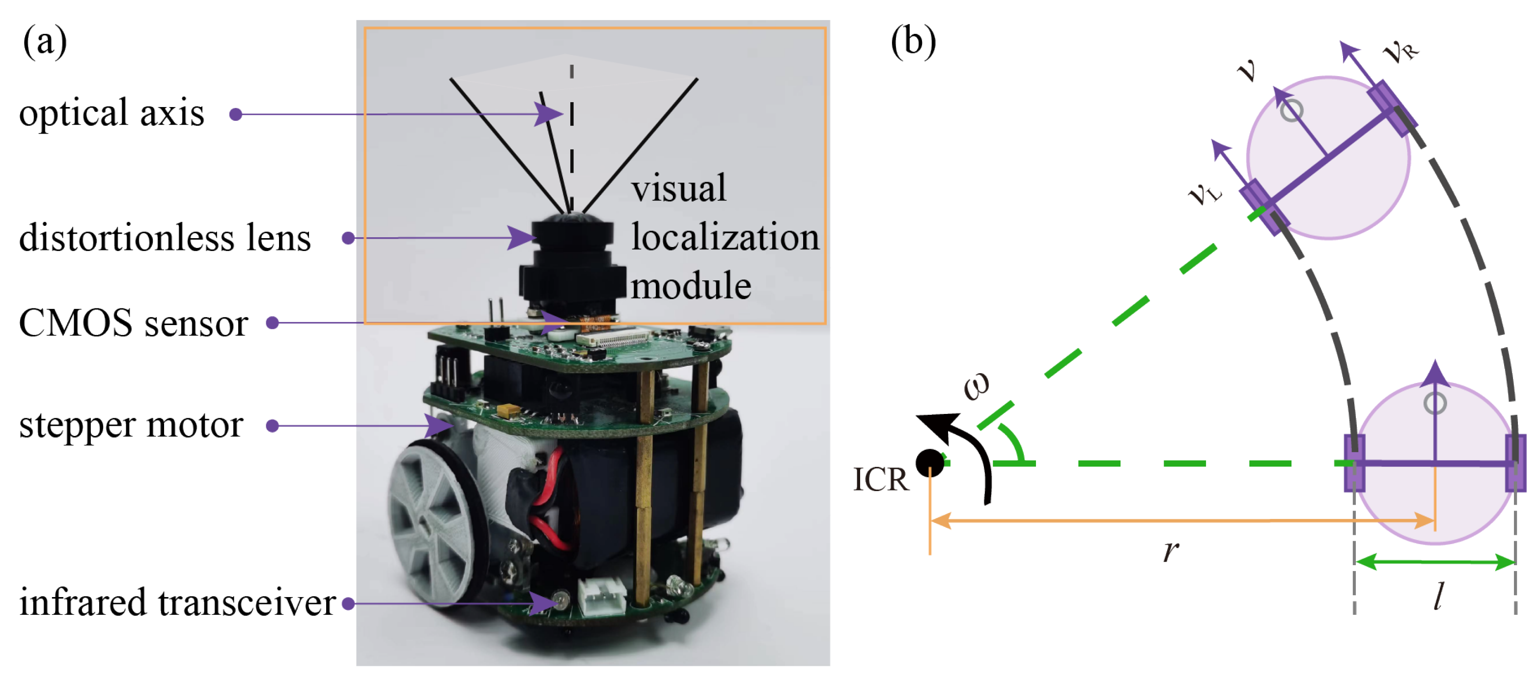
3.1. Miniature Swarm Robots
3.2. Design and Recognition of Optical Beacons
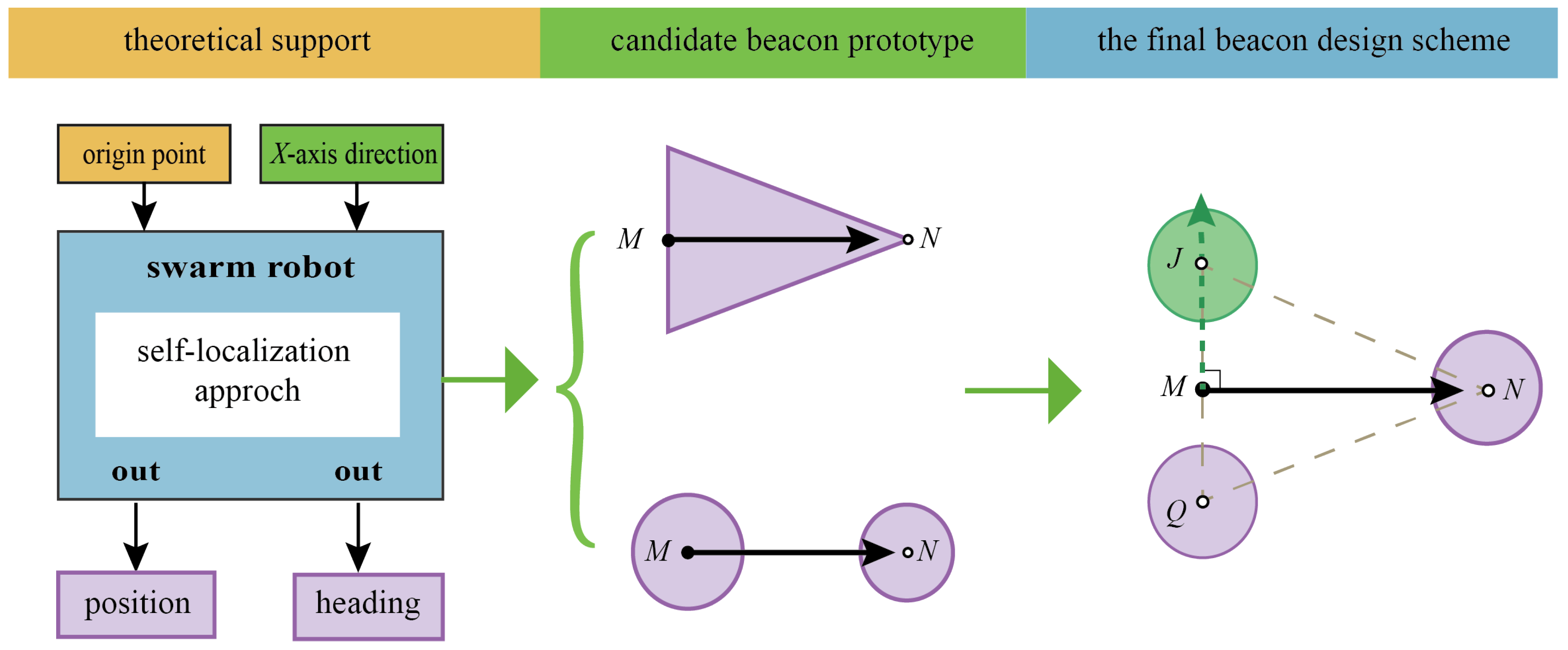
3.2.1. Design of Optical Beacons
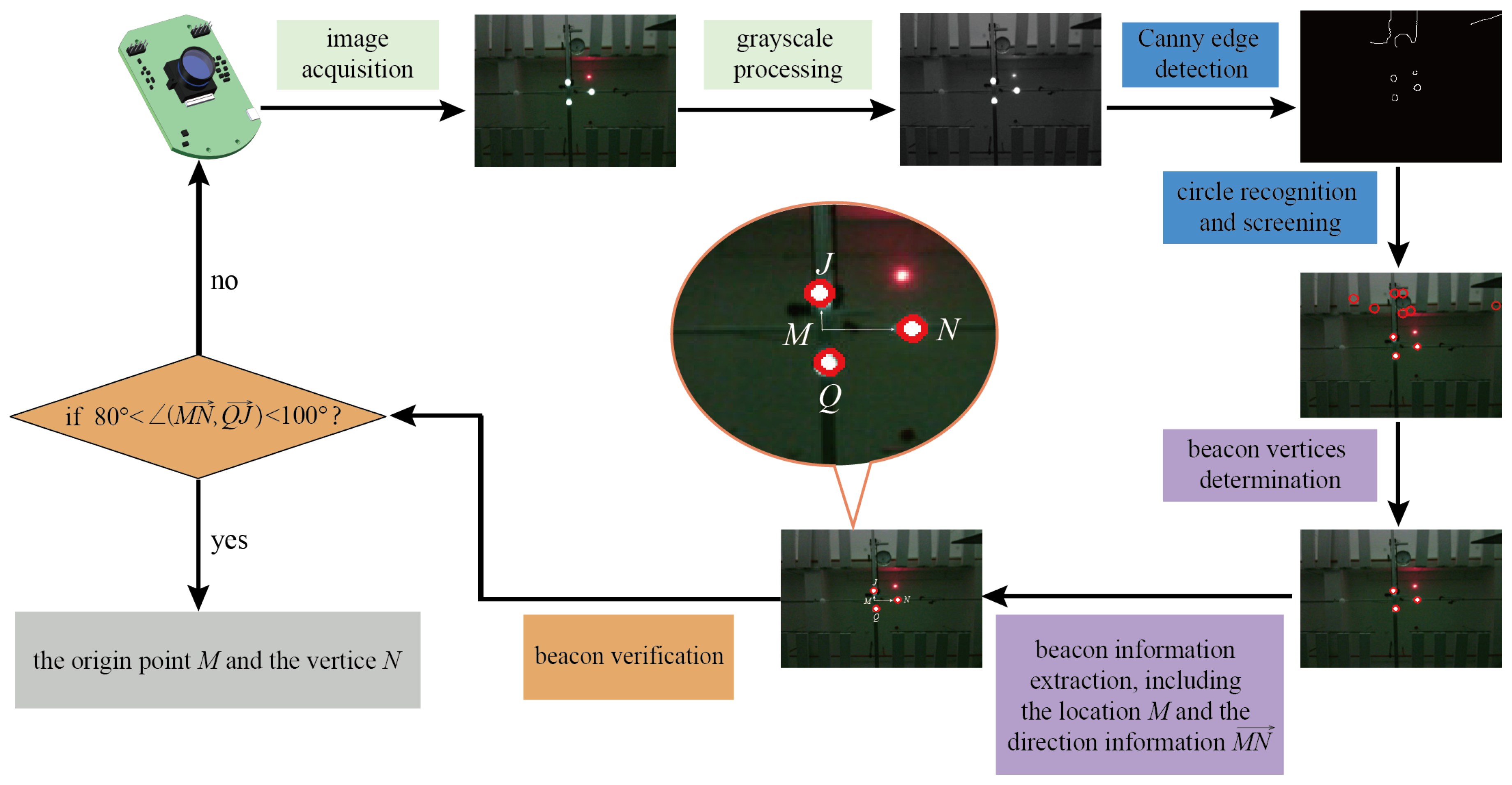
3.2.2. Recognition and Verification of Beacons
3.3. Relative Localization
4. Experimental Results
4.1. Experiment Set-Up
- (1)
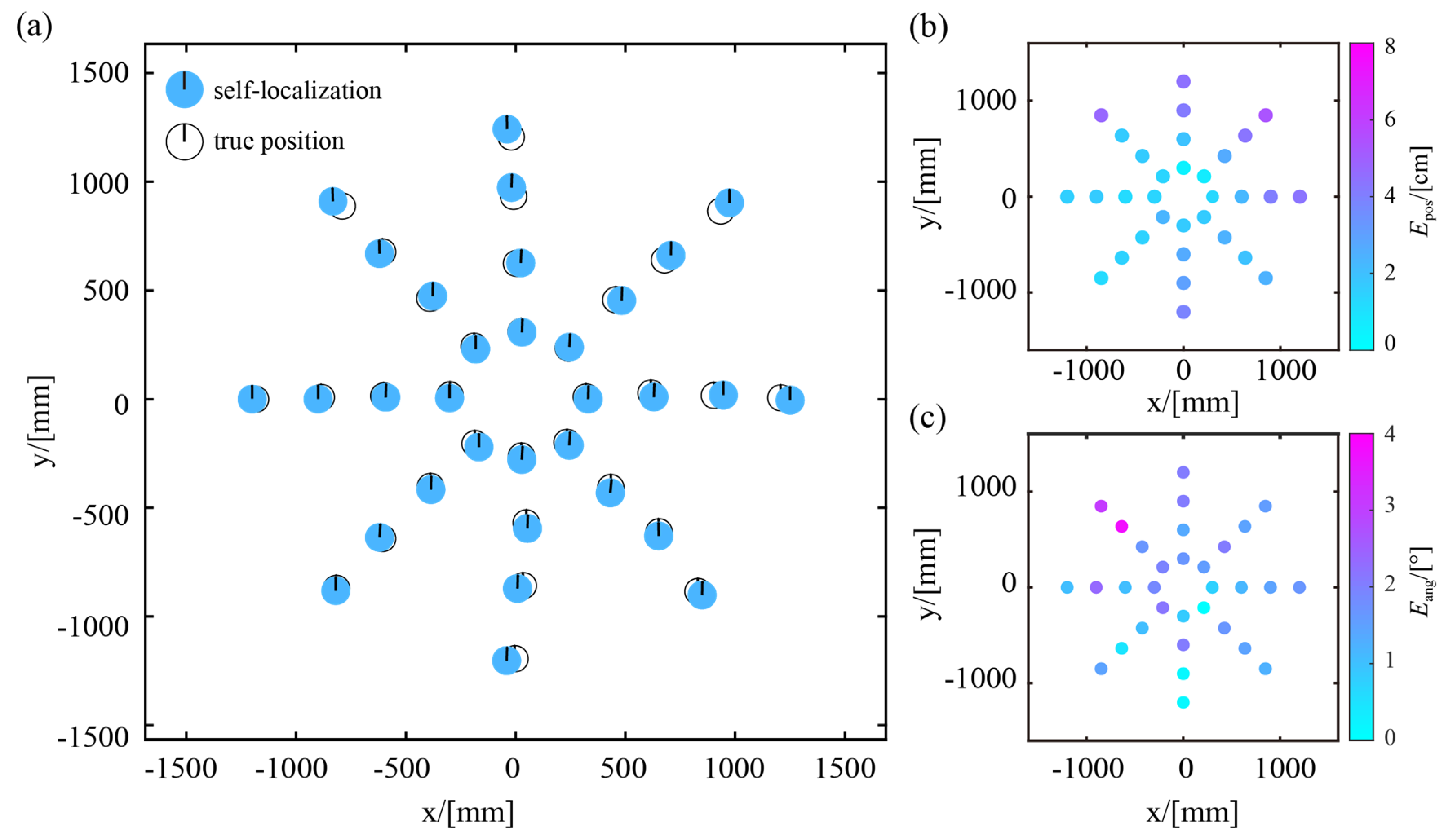
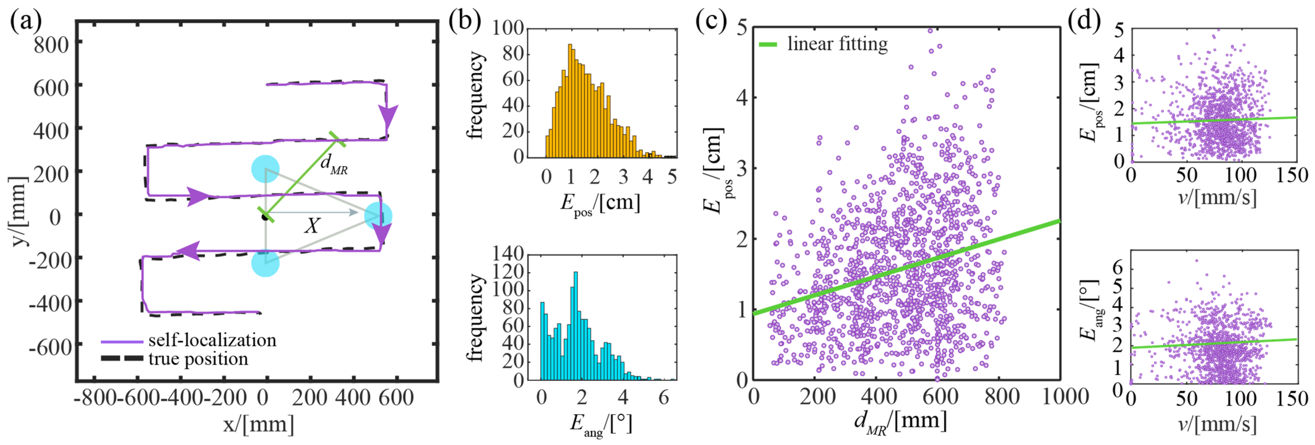
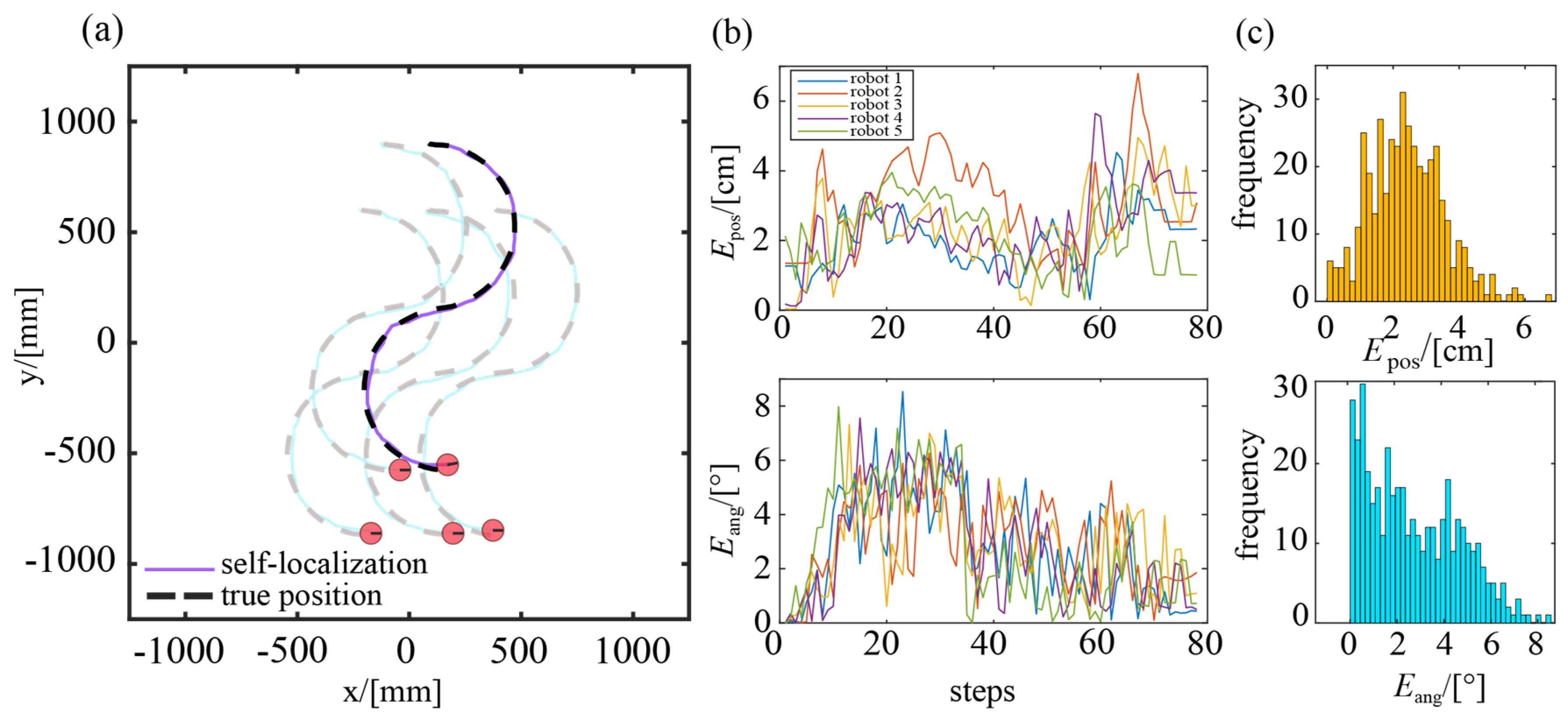
- The position error, , is defined as the Euclidean distance between the true position and the estimated position of the self-localization module:
- (2)
- The heading error, , is defined as the absolute value of the error between the true heading and the estimated heading obtained of the self-localization module.
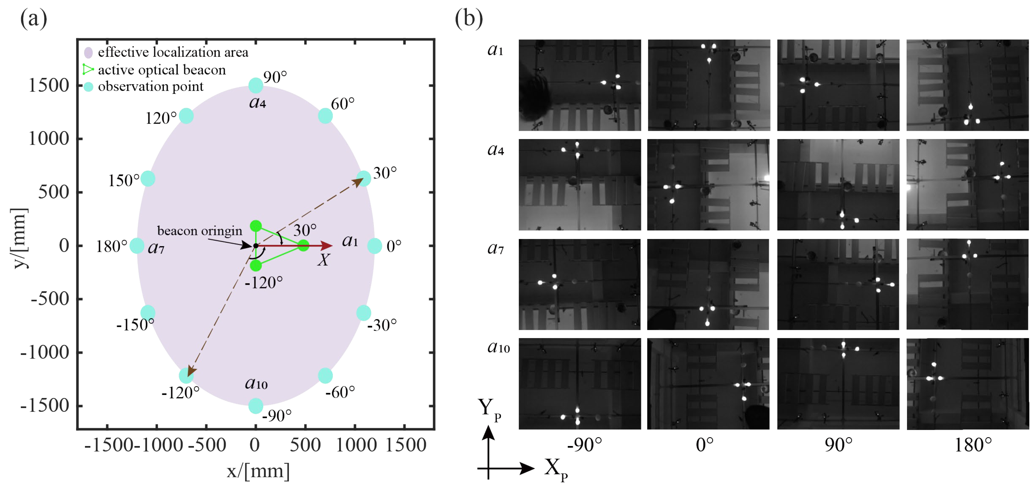
4.2. Experiment of Effective Self-Localization Area
4.3. Experiment of Static Localization
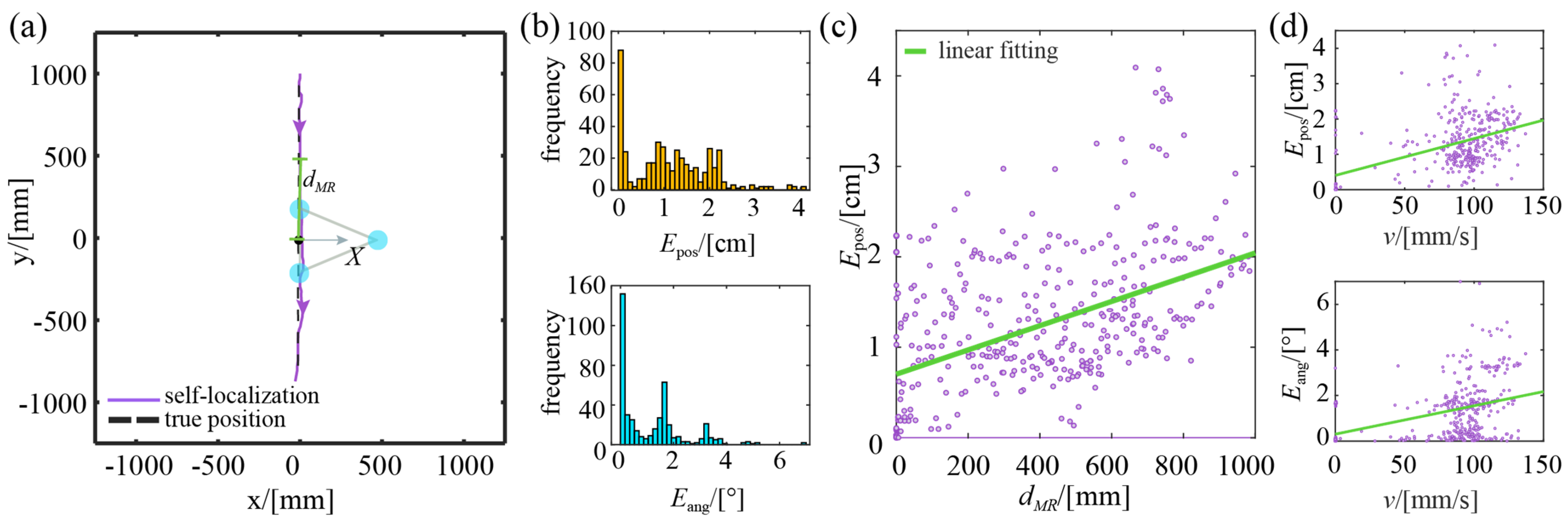
4.4. Experiment of Dynamic Localization
4.4.1. Straight Trajectory
4.4.2. Square Trajectory
4.4.3. Self-Localization Experiment for a Swarm of Robots
5. Conclusions
Author Contributions
Funding
Institutional Review Board Statement
Informed Consent Statement
Data Availability Statement
Conflicts of Interest
References
- Dorigo, M.; Theraulaz, G.; Trianni, V. Swarm robotics: Past, present, and future [point of view]. Proc. IEEE 2021, 109, 1152–1165. [Google Scholar] [CrossRef]
- Tang, Q.; Xu, Z.; Yu, F.; Zhang, Z.; Zhang, J. Dynamic target searching and tracking with swarm robots based on stigmergy mechanism. Robot. Auton. Syst. 2019, 120, 103251. [Google Scholar] [CrossRef]
- Hu, J.; Liu, W.; Zhang, H.; Yi, J.; Xiong, Z. Multi-robot object transport motion planning with a deformable sheet. IEEE Robot. Autom. Lett. 2022, 7, 9350–9357. [Google Scholar] [CrossRef]
- Lei, X.; Zhang, S.; Xiang, Y.; Duan, M. Self-organized multi-target trapping of swarm robots with density-based interaction. Complex Intell. Syst. 2023. [Google Scholar] [CrossRef]
- Zhang, S.; Pan, J. Collecting a flock with multiple sub-groups by using multi-robot system. IEEE Robot. Autom. Lett. 2022, 7, 6974–6981. [Google Scholar] [CrossRef]
- Darmanin, R.N.; Bugeja, M.K. A Review on Multi-Robot Systems Categorised by Application Domain. In Proceedings of the 2017 25th Mediterranean Conference on Control and Automation (MED), Valletta, Malta, 3–6 July 2017; pp. 701–706. [Google Scholar]
- Zhang, K.; Chermprayong, P.; Xiao, F.; Tzoumanikas, D.; Dams, B.; Kay, S.; Kocer, B.B.; Burns, A.; Orr, L.; Choi, C. Aerial additive manufacturing with multiple autonomous robots. Nature 2022, 609, 709–717. [Google Scholar] [CrossRef]
- Youssefi, K.A.-R.; Rouhani, M.; Mashhadi, H.R.; Elmenreich, W. A swarm intelligence-based robotic search algorithm integrated with game theory. Appl. Soft Comput. 2022, 122, 108873. [Google Scholar] [CrossRef]
- Ohno, K.; Tsubouchi, T.; Shigematsu, B.; Yuta, S.i. Differential GPS and odometry-based outdoor navigation of a mobile robot. Adv. Robot. 2004, 18, 611–635. [Google Scholar] [CrossRef]
- Park, J.; Cho, Y.K.; Martinez, D. A BIM and UWB integrated mobile robot navigation system for indoor position tracking applications. J. Constr. Eng. Proj. Manag. 2016, 6, 30–39. [Google Scholar] [CrossRef]
- Mayya, S.; Pierpaoli, P.; Nair, G.; Egerstedt, M. Localization in densely packed swarms using interrobot collisions as a sensing modality. IEEE Trans. Robot. 2018, 35, 21–34. [Google Scholar] [CrossRef]
- Garcia, M.; Tomas, J.; Boronat, F.; Lloret, J. The Development of Two Systems for Indoor Wireless Sensors Self-location. Ad Hoc Sens. Wirel. Netw. 2009, 8, 235–258. [Google Scholar]
- Schuster, F.; Keller, C.G.; Rapp, M.; Haueis, M.; Curio, C. Landmark based radar SLAM using graph optimization. In Proceedings of the 2016 IEEE 19th International Conference on Intelligent Transportation Systems (ITSC), Rio de Janeiro, Brazil, 1–4 November 2016; pp. 2559–2564. [Google Scholar]
- Yousif, K.; Bab-Hadiashar, A.; Hoseinnezhad, R. An overview to visual odometry and visual SLAM: Applications to mobile robotics. Intell. Ind. Syst. 2015, 1, 289–311. [Google Scholar] [CrossRef]
- Mao, L.; Chen, J.; Li, Z.; Zhang, D. Relative localization method of multiple micro robots based on simple sensors. Int. J. Adv. Robot. Syst. 2013, 10, 128. [Google Scholar] [CrossRef]
- Kim, J.Y.; Kashino, Z.; Pineros, L.M.; Bayat, S.; Colaco, T.; Nejat, G.; Benhabib, B. A high-performance millirobot for swarm-behaviour studies: Swarm-topology estimation. Int. J. Adv. Robot. Syst. 2019, 16, 1729881419892127. [Google Scholar] [CrossRef]
- Wang, S.; Li, Y.; Zhang, S.; Wang, B.; Yang, H. Relative localization of swarm robotics based on the polar method. Int. J. Adv. Robot. Syst. 2022, 19, 17298806221080634. [Google Scholar] [CrossRef]
- Tan, L.N. Omnidirectional-vision-based distributed optimal tracking control for mobile multirobot systems with kinematic and dynamic disturbance rejection. IEEE Trans. Ind. Electron. 2017, 65, 5693–5703. [Google Scholar] [CrossRef]
- Bonani, M.; Longchamp, V.; Magnenat, S.; Rétornaz, P.; Burnier, D.; Roulet, G.; Vaussard, F.; Bleuler, H.; Mondada, F. The marXbot, a Miniature Mobile Robot Opening New Perspectives for the Collective-Robotic Research. In Proceedings of the 2010 IEEE/RSJ International Conference on Intelligent Robots and Systems, Taiwan, China, 18–22 October 2010; pp. 4187–4193. [Google Scholar]
- Wang, X.; Wang, F.; Nie, Z.; Ai, Y.; Hu, T. OptiSwarm: Optical Swarm Robots Using Implicit Cooperation. IEEE Sens. J. 2022, 22, 24380–24394. [Google Scholar] [CrossRef]
- Inoue, D.; Murai, D.; Ikuta, Y.; Yoshida, H. Distributed Range-Based Localization for Swarm Robot Systems Using Sensor-fusion Technique. In Proceedings of the SENSORNETS 2019: 8th International Conference on Sensor Networks, Prague, Czech Republic, 26–27 February 2019; pp. 13–22. [Google Scholar]
- Li, Y.; Zhu, S.; Yu, Y.; Wang, Z. An improved graph-based visual localization system for indoor mobile robot using newly designed markers. Int. J. Adv. Robot. Syst. 2018, 15, 1729881418769191. [Google Scholar] [CrossRef]
- Voelkl, B.; Portugal, S.J.; Unsöld, M.; Usherwood, J.R.; Wilson, A.M.; Fritz, J. Matching times of leading and following suggest cooperation through direct reciprocity during V-formation flight in ibis. Proc. Natl. Acad. Sci. USA 2015, 112, 2115–2120. [Google Scholar] [CrossRef]
- Grüter, C.; Farina, W.M. The honeybee waggle dance: Can we follow the steps? Trends Ecol. Evol. 2009, 24, 242–247. [Google Scholar] [CrossRef]
- Ansari, M.A.; Kurchaniya, D.; Dixit, M. A comprehensive analysis of image edge detection techniques. Int. J. Multimed. Ubiquitous Eng. 2017, 12, 1–12. [Google Scholar] [CrossRef]
- Djekoune, A.O.; Messaoudi, K.; Amara, K. Incremental circle hough transform: An improved method for circle detection. Optik 2017, 133, 17–31. [Google Scholar] [CrossRef]
- Mori, M.; Kashino, K. Fast Template Matching Based on Normalized Cross Correlation Using Adaptive Block Partitioning and Initial Threshold Estimation. In Proceedings of the 2010 IEEE International Symposium on Multimedia, Taiwan, China, 13–15 December 2010; pp. 196–203. [Google Scholar]
- Grossberg, M.D.; Nayar, S.K. A General Imaging Model and a Method for Finding Its Parameters. In Proceedings of the Eighth IEEE International Conference on Computer Vision, ICCV 2001, Vancouver, BC, Canada, 7–14 July 2001; pp. 108–115. [Google Scholar]
- Sels, S.; Ribbens, B.; Vanlanduit, S.; Penne, R. Camera calibration using gray code. Sensors 2019, 19, 246. [Google Scholar] [CrossRef] [PubMed]
- Gong, D.; Yang, J.; Liu, L.; Zhang, Y.; Reid, I.; Shen, C.; Van Den Hengel, A.; Shi, Q. From Motion Blur to Motion Flow: A Deep Learning Solution for Removing Heterogeneous Motion Blur. In Proceedings of the IEEE Conference on Computer Vision and Pattern Recognition, Honolulu, HI, USA, 21–26 July 2017; pp. 2319–2328. [Google Scholar]


| No. | Average Position Error (cm) | Position Error Variance | Average Heading Error (°) | Heading Error Variance |
|---|---|---|---|---|
| 1 | 0.73 | 0.38 | 0.83 | 0.82 |
| 2 | 0.90 | 0.94 | 0.74 | 0.70 |
| 3 | 1.41 | 0.79 | 1.04 | 1.82 |
| 4 | 1.07 | 0.51 | 1.41 | 1.95 |
| 5 | 1.62 | 0.71 | 2.03 | 1.73 |
| No. | Average Position Error (cm) | Position Error Variance | Average Heading Error (°) | Heading Error Variance |
|---|---|---|---|---|
| 1 | 1.41 | 0.64 | 1.31 | 0.72 |
| 2 | 1.49 | 0.83 | 2.02 | 1.12 |
| 3 | 1.81 | 0.77 | 1.89 | 1.34 |
| 4 | 1.53 | 0.84 | 1.37 | 1.08 |
| 5 | 1.55 | 0.73 | 2.32 | 1.48 |
| Robot ID | Average Position Error (cm) | Position Error Variance | Average Heading Error (°) | Heading Error Variance |
|---|---|---|---|---|
| 1 | 2.02 | 0.66 | 2.63 | 4.28 |
| 2 | 3.09 | 0.42 | 2.96 | 2.17 |
| 3 | 2.38 | 1.24 | 2.76 | 3.13 |
| 4 | 2.42 | 0.60 | 2.60 | 4.32 |
| 5 | 2.11 | 0.89 | 2.62 | 4.66 |
Disclaimer/Publisher’s Note: The statements, opinions and data contained in all publications are solely those of the individual author(s) and contributor(s) and not of MDPI and/or the editor(s). MDPI and/or the editor(s) disclaim responsibility for any injury to people or property resulting from any ideas, methods, instructions or products referred to in the content. |
© 2023 by the authors. Licensee MDPI, Basel, Switzerland. This article is an open access article distributed under the terms and conditions of the Creative Commons Attribution (CC BY) license (https://creativecommons.org/licenses/by/4.0/).
Share and Cite
Duan, M.; Lei, X.; Duan, Z.; Zheng, Z. A Minimalist Self-Localization Approach for Swarm Robots Based on Active Beacon in Indoor Environments. Sensors 2023, 23, 4926. https://doi.org/10.3390/s23104926
Duan M, Lei X, Duan Z, Zheng Z. A Minimalist Self-Localization Approach for Swarm Robots Based on Active Beacon in Indoor Environments. Sensors. 2023; 23(10):4926. https://doi.org/10.3390/s23104926
Chicago/Turabian StyleDuan, Mengyuan, Xiaokang Lei, Zhongxing Duan, and Zhicheng Zheng. 2023. "A Minimalist Self-Localization Approach for Swarm Robots Based on Active Beacon in Indoor Environments" Sensors 23, no. 10: 4926. https://doi.org/10.3390/s23104926