
Inertial Sensor-to-Segment Calibration for Accurate 3D Joint Angle Calculation for Use in OpenSim

 ,
,  , ,
, ,  ,
,  and
and
Abstract
:1. Introduction
2. Materials and Methods
2.1. Data Collection
2.2. Instrumentation
2.3. Protocol
2.4. Kinematics Analysis
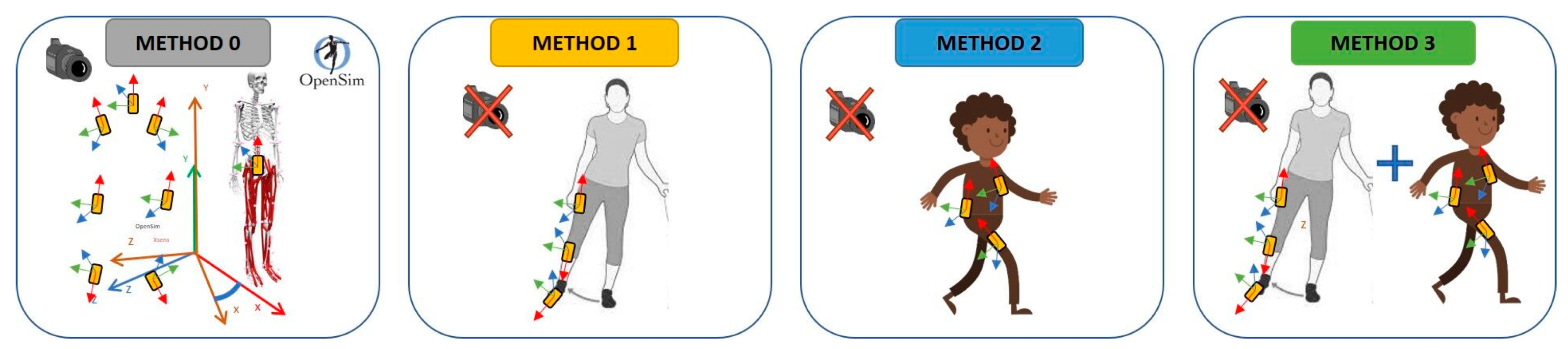
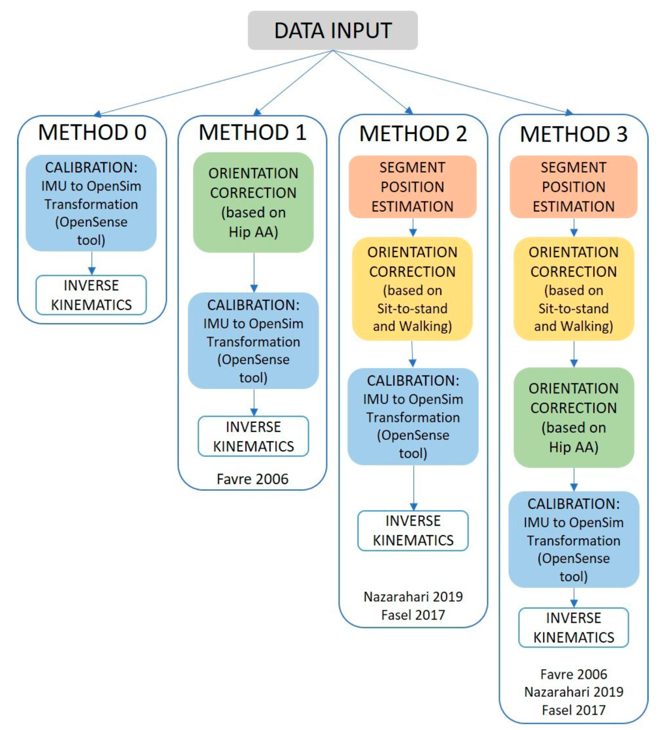
2.5. Sensor-to-Segment Calibration
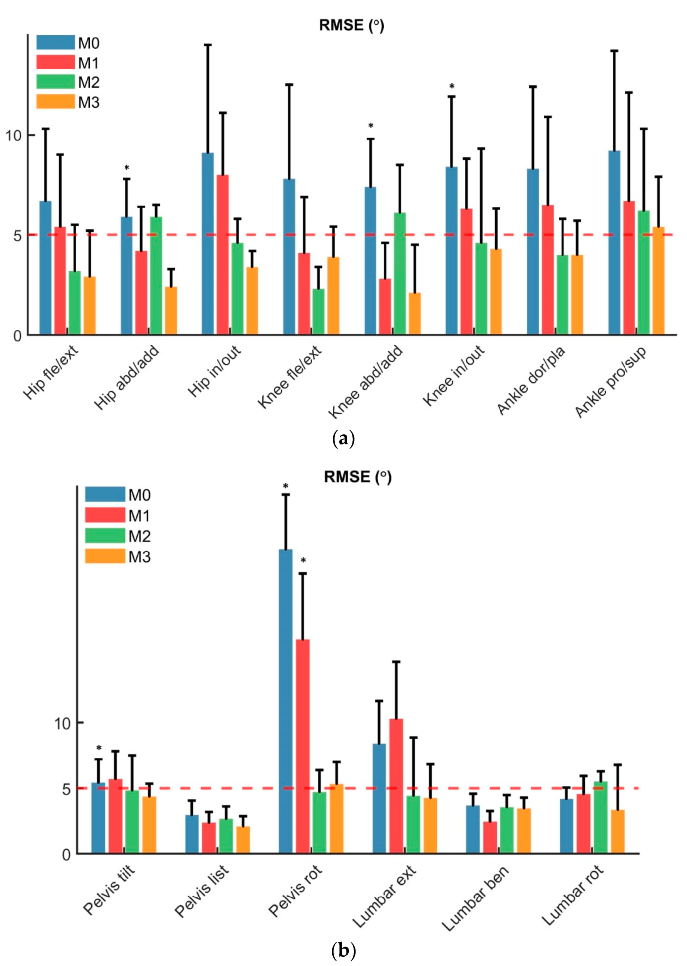
2.6. Statistics
3. Results
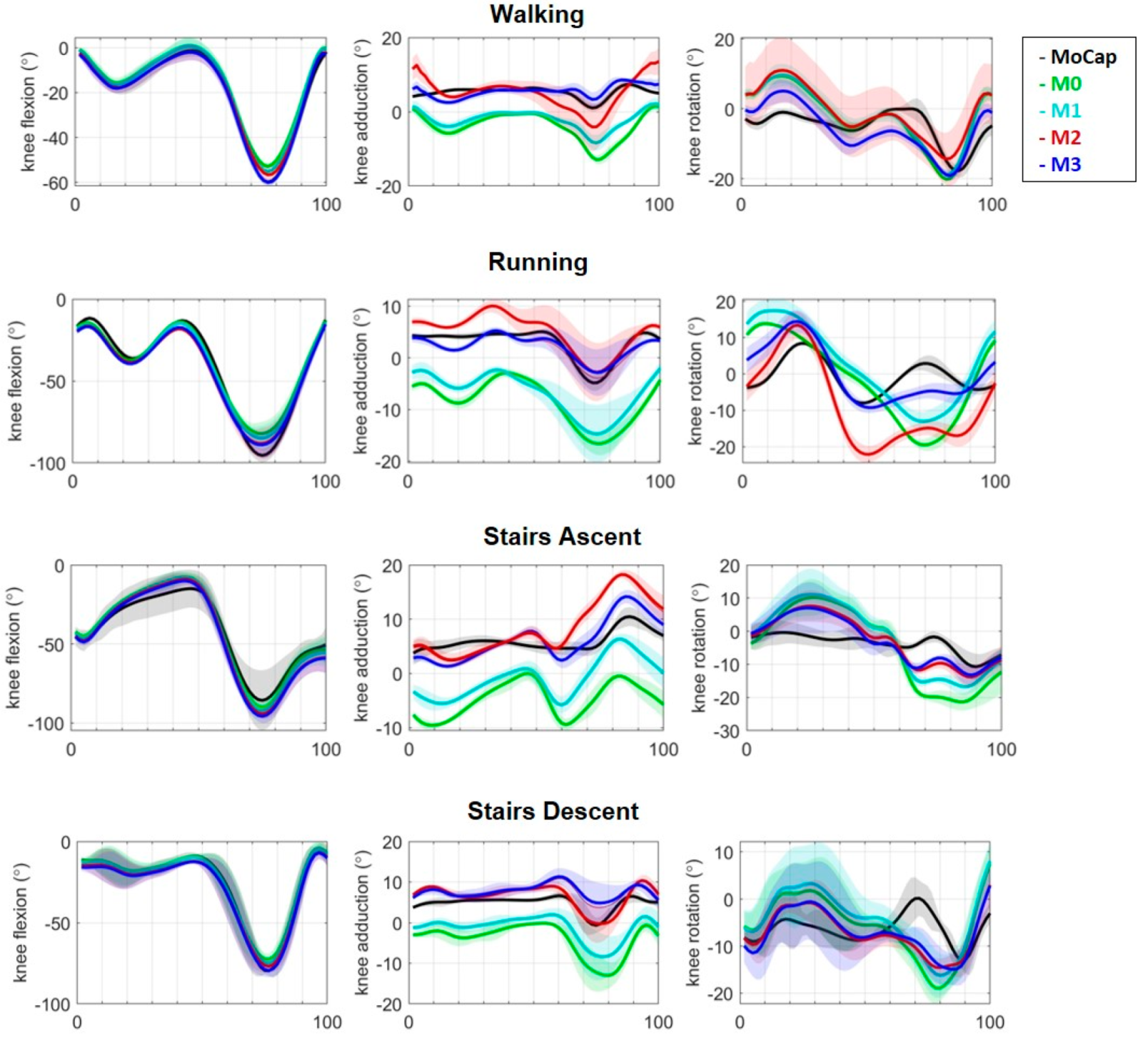
3.1. Walking
3.2. Running and Stair Ascent and Descent
4. Discussion
Summary and Main Findings
5. Conclusions
Supplementary Materials
Author Contributions
Funding
Institutional Review Board Statement
Informed Consent Statement
Data Availability Statement
Conflicts of Interest
References
- Richards, R.; Noort, J.V.D.; van der Esch, M.; Booij, M.; Harlaar, J. Gait retraining using real-time feedback in patients with medial knee osteoarthritis: Feasibility and effects of a six-week gait training program. Knee 2018, 25, 814–824. [Google Scholar] [CrossRef]
- Iijima, H.; Shimoura, K.; Ono, T.; Aoyama, T.; Takahashi, M. Proximal gait adaptations in individuals with knee osteoarthritis: A systematic review and meta-analysis. J. Biomech. 2019, 87, 127–141. [Google Scholar] [CrossRef]
- Karatsidis, A.; Richards, R.E.; Konrath, J.M.; van den Noort, J.C.; Schepers, H.M.; Bellusci, G.; Harlaar, J.; Veltink, P.H. Validation of wearable visual feedback for retraining foot progression angle using inertial sensors and an augmented reality headset. J. Neuroeng. Rehabil. 2018, 15, 78. [Google Scholar] [CrossRef] [PubMed]
- Gerbrands, T.; Pisters, M.; Vanwanseele, B. Individual selection of gait retraining strategies is essential to optimally reduce medial knee load during gait. Clin. Biomech. 2014, 29, 828–834. [Google Scholar] [CrossRef]
- Barrios, J.A.; Crossley, K.M.; Davis, I.S. Gait retraining to reduce the knee adduction moment through real-time visual feedback of dynamic knee alignment. J. Biomech. 2010, 43, 2208–2213. [Google Scholar] [CrossRef] [Green Version]
- Lee, S.I.; Eskofier, B.M. Special issue on wearable computing and machine learning for applications in sports, health, and medical engineering. Appl. Sci. 2018, 8, 167. [Google Scholar] [CrossRef] [Green Version]
- Adesida, Y.; Papi, E.; McGregor, A.H. Exploring the role of wearable technology in sport kinematics and kinetics: A systematic review. Sensors 2019, 19, 1597. [Google Scholar] [CrossRef] [PubMed] [Green Version]
- Pacher, L.; Fradet, L.; Tarent, Y.; Retailleau, M.; Colloud, F.; Chatellier, C.; Vauzelle, R. Pelvis and hip calibration methods for movement analysis with inertial sensors. Comput. Methods Biomech. Biomed. Eng. 2019, 22, S166–S168. [Google Scholar] [CrossRef]
- Picerno, P. 25 years of lower limb joint kinematics by using inertial and magnetic sensors: A review of methodological approaches. Gait Posture 2017, 51, 239–246. [Google Scholar] [CrossRef]
- Weygers, I.; Kok, M.; Konings, M.; Hallez, H.; De Vroey, H.; Claeys, K. Inertial sensor-based lower limb joint kinematics: A methodological systematic review. Sensors 2020, 20, 673. [Google Scholar] [CrossRef] [PubMed] [Green Version]
- Poitras, I.; Dupuis, F.; Bielmann, M.; Campeau-Lecours, A.; Mercier, C.; Bouyer, L.J.; Roy, J.-S. Validity and reliability of wearable sensors for joint angle estimation: A systematic review. Sensors 2019, 19, 1555. [Google Scholar] [CrossRef] [Green Version]
- Dejnabadi, H.; Jolles, B.; Aminian, K. A new approach to accurate measurement of uniaxial joint angles based on a combination of accelerometers and gyroscopes. IEEE Trans. Biomed. Eng. 2005, 52, 1478–1484. [Google Scholar] [CrossRef] [PubMed]
- Iosa, M.; Picerno, P.; Paolucci, S.; Morone, G. Wearable inertial sensors for human movement analysis. Expert Rev. Med. Devices 2016, 13, 641–659. [Google Scholar] [CrossRef] [PubMed]
- Ornetti, P.; Maillefert, J.-F.; Laroche, D.; Morisset, C.; Dougados, M.; Gossec, L. Gait analysis as a quantifiable outcome measure in hip or knee osteoarthritis: A systematic review. Jt. Bone Spine 2010, 77, 421–425. [Google Scholar] [CrossRef]
- Benson, L.C.; Clermont, C.A.; Bošnjak, E.; Ferber, R. The use of wearable devices for walking and running gait analysis outside of the lab: A systematic review. Gait Posture 2018, 63, 124–138. [Google Scholar] [CrossRef] [PubMed]
- Meireles, S.; De Groote, F.; Van Rossom, S.; Verschueren, S.; Jonkers, I. Differences in knee adduction moment between healthy subjects and patients with osteoarthritis depend on the knee axis definition. Gait Posture 2017, 53, 104–109. [Google Scholar] [CrossRef] [PubMed]
- Kaufman, K.R.; Hughes, C.; Morrey, B.F.; Morrey, M.; An, K.-N. Gait characteristics of patients with knee osteoarthritis. J. Biomech. 2001, 34, 907–915. [Google Scholar] [CrossRef]
- Bejek, Z.; Paróczai, R.; Illyés, Á.; Kiss, R.M. The influence of walking speed on gait parameters in healthy people and in patients with osteoarthritis. Knee Surgery, Sports Traumatol. Arthrosc. 2006, 14, 612–622. [Google Scholar] [CrossRef] [PubMed]
- Zhang, L.; Liu, G.; Han, B.; Yan, Y.; Fei, J.; Ma, J.; Zhang, Y. A Comparison of Dynamic and Static Hip-Knee-Ankle Angle during Gait in Knee Osteoarthritis Patients and Healthy Individuals. Appl. Bionics Biomech. 2021, 2021, 6231406. [Google Scholar] [CrossRef] [PubMed]
- Maly, M.R.; Costigan, P.A.; Olney, S.J. Role of knee kinematics and kinetics on performance and disability in people with medial compartment knee osteoarthritis. Clin. Biomech. 2006, 21, 1051–1059. [Google Scholar] [CrossRef]
- Rudolph, K.S.; Schmitt, L.C.; Lewek, M.D. Age-related changes in strength, joint laxity, and walking patterns: Are they related to knee osteoarthritis? Phys. Ther. 2007, 87, 1422–1432. [Google Scholar] [CrossRef] [PubMed] [Green Version]
- Linley, H.S.; Sled, E.A.; Culham, E.G.; Deluzio, K.J. A biomechanical analysis of trunk and pelvis motion during gait in subjects with knee osteoarthritis compared to control subjects. Clin. Biomech. 2010, 25, 1003–1010. [Google Scholar] [CrossRef]
- Bennour, S.; Ulrich, B.; Legrand, T.; Jolles, B.M.; Favre, J. A gait retraining system using augmented-reality to modify footprint parameters: Effects on lower-limb sagittal-plane kinematics. J. Biomech. 2018, 66, 26–35. [Google Scholar] [CrossRef]
- Pacher, L.; Chatellier, C.; Vauzelle, R.; Fradet, L. Sensor-to-segment calibration methodologies for lower-body kinematic analysis with inertial sensors: A systematic review. Sensors 2020, 20, 3322. [Google Scholar] [CrossRef]
- Robert-Lachaine, X.; Parent, G.; Fuentes, A.; Hagemeister, N.; Aissaoui, R. Inertial motion capture validation of 3D knee kinematics at various gait speed on the treadmill with a double-pose calibration. Gait Posture 2020, 77, 132–137. [Google Scholar] [CrossRef]
- Fan, B.; Li, Q.; Tan, T.; Kang, P.; Shull, P.B. Effects of IMU Sensor-to-Segment Misalignment and Orientation Error on 3D Knee Joint Angle Estimation. IEEE Sens. J. 2021, 22, 2543–2552. [Google Scholar] [CrossRef]
- Paulich, M.; Schepers, M.; Rudigkeit, N.; Bellusci, G. Xsens MTw Awinda: Miniature Wireless Inertial-Magnetic Motion Tracker for Highly Accurate 3D Kinematic Applications. Xsens Technol. 2018, 1–9. [Google Scholar] [CrossRef]
- Berner, K.; Cockcroft, J.; Morris, L.D.; Louw, Q. Concurrent validity and within-session reliability of gait kinematics measured using an inertial motion capture system with repeated calibration. J. Bodyw. Mov. Ther. 2020, 24, 251–260. [Google Scholar] [CrossRef] [PubMed]
- Fan, B.; Xia, H.; Xu, J.; Li, Q.; Shull, P.B. IMU-based knee flexion, abduction and internal rotation estimation during drop landing and cutting tasks. J. Biomech. 2021, 124, 110549. [Google Scholar] [CrossRef]
- Faber, G.S.; Chang, C.-C.; Rizun, P.; Dennerlein, J. A novel method for assessing the 3-D orientation accuracy of inertial/magnetic sensors. J. Biomech. 2013, 46, 2745–2751. [Google Scholar] [CrossRef]
- Delp, S.L.; Anderson, F.C.; Arnold, A.S.; Loan, P.; Habib, A.; John, C.T.; Guendelman, E.; Thelen, D.G. OpenSim: Open-source software to create and analyze dynamic simulations of movement. IEEE Trans. Biomed. Eng. 2007, 54, 1940–1950. [Google Scholar] [CrossRef] [Green Version]
- Al Borno, M.; O’Day, J.; Ibarra, V.; Dunne, J.; Seth, A.; Habib, A.; Ong, C.; Hicks, J.; Uhlrich, S.; Delp, S. OpenSense: An open-source toolbox for inertial-measurement-unit-based measurement of lower extremity kinematics over long durations. J. Neuroeng. Rehabil. 2022, 19, 22. [Google Scholar] [CrossRef] [PubMed]
- Favre, J.; Luthi, F.; Jolles, B.M.; Siegrist, O.; Najafi, B.; Aminian, K. A new ambulatory system for comparative evaluation of the three-dimensional knee kinematics, applied to anterior cruciate ligament injuries. Knee Surg. Sports Traumatol. Arthrosc. 2006, 14, 592–604. [Google Scholar] [CrossRef] [Green Version]
- Favre, J.; Jolles, B.; Aissaoui, R.; Aminian, K. Ambulatory measurement of 3D knee joint angle. J. Biomech. 2008, 41, 1029–1035. [Google Scholar] [CrossRef]
- Cordillet, S.; Bideau, N.; Bideau, B.; Nicolas, G. Estimation of 3D knee joint angles during cycling using inertial sensors: Accuracy of a novel sensor-to-segment calibration procedure based on pedaling motion. Sensors 2019, 19, 2474. [Google Scholar] [CrossRef] [Green Version]
- Fasel, B.; Spörri, J.; Schütz, P.; Lorenzetti, S.; Aminian, K. Validation of functional calibration and strap-down joint drift correction for computing 3D joint angles of knee, hip, and trunk in alpine skiing. PLoS ONE 2017, 12, e0181446. [Google Scholar] [CrossRef] [PubMed]
- Fasel, B.; Spörri, J.; Schütz, P.; Lorenzetti, S.; Aminian, K. An inertial sensor-based method for estimating the athlete’s relative joint center positions and center of mass kinematics in alpine ski racing. Front. Physiol. 2017, 8, 850. [Google Scholar] [CrossRef]
- Picerno, P.; Cereatti, A.; Cappozzo, A. Joint kinematics estimate using wearable inertial and magnetic sensing modules. Gait Posture 2008, 28, 588–595. [Google Scholar] [CrossRef]
- Picerno, P.; Caliandro, P.; Iacovelli, C.; Simbolotti, C.; Crabolu, M.; Pani, D.; Vannozzi, G.; Reale, G.; Rossini, P.M.; Padua, L.; et al. Upper limb joint kinematics using wearable magnetic and inertial measurement units: An anatomical calibration procedure based on bony landmark identification. Sci. Rep. 2019, 9, 14449. [Google Scholar] [CrossRef] [PubMed]
- Palermo, E.; Rossi, S.; Marini, F.; Patane, F.; Cappa, P. Experimental evaluation of accuracy and repeatability of a novel body-to-sensor calibration procedure for inertial sensor-based gait analysis. Meas. J. Int. Meas. Confed. 2014, 52, 145–155. [Google Scholar] [CrossRef]
- LeBleu, J.; Gosseye, T.; Detrembleur, C.; Mahaudens, P.; Cartiaux, O.; Penta, M. Lower limb kinematics using inertial sensors during locomotion: Accuracy and reproducibility of joint angle calculations with different sensor-to-segment calibrations. Sensors 2020, 20, 715. [Google Scholar] [CrossRef] [Green Version]
- Rosso, V.; Agostini, V.; Takeda, R.; Tadano, S.; Gastaldi, L. Influence of BMI on gait characteristics of young adults: 3D evaluation using inertial sensors. Sensors 2019, 19, 4221. [Google Scholar] [CrossRef] [Green Version]
- Versteyhe, M.; De Vroey, H.; DeBrouwere, F.; Hallez, H.; Claeys, K. A novel method to estimate the full knee joint kinematics using low cost IMU sensors for easy to implement low cost diagnostics. Sensors 2020, 20, 1683. [Google Scholar] [CrossRef] [Green Version]
- Roetenberg, D.; Luinge, H.; Slycke, P. Xsens MVN: Full 6DOF human motion tracking using miniature inertial sensors. Xsens Motion Technol. BV Technol. Rep. 2009, 1, 1–7. [Google Scholar]
- Hamner, S.R.; Seth, A.; Delp, S.L. Muscle contributions to propulsion and support during running. J. Biomech. 2010, 43, 2709–2716. [Google Scholar] [CrossRef] [PubMed] [Green Version]
- Nazarahari, M.; Noamani, A.; Ahmadian, N.; Rouhani, H. Sensor-to-body calibration procedure for clinical motion analysis of lower limb using magnetic and inertial measurement units. J. Biomech. 2019, 85, 224–229. [Google Scholar] [CrossRef] [PubMed]
- Fasel, B.; Spörri, J.; Chardonnens, J.; Kroll, J.; Muller, E.; Aminian, K. Joint Inertial Sensor Orientation Drift Reduction for Highly Dynamic Movements. IEEE J. Biomed. Health Inform. 2018, 22, 77–86. [Google Scholar] [CrossRef] [PubMed]
- Nazarahari, M.; Rouhani, H. Semi-Automatic Sensor-to-Body Calibration of Inertial Sensors on Lower Limb Using Gait Recording. IEEE Sens. J. 2019, 19, 12465–12474. [Google Scholar] [CrossRef]
- Schepers, M.; Giuberti, M.; Bellusci, G. Xsens MVN: Consistent tracking of human motion using inertial sensing. Xsens Technol. 2018, 1, 1–8. [Google Scholar] [CrossRef]
- Wu, G.; Siegler, S.; Allard, P.; Kirtley, C.; Leardini, A.; Rosenbaum, D.; Whittle, M.; D’Lima, D.D.; Cristofolini, L.; Witte, H.; et al. ISB recommendation on definitions of joint coordinate system of various joints for the reporting of human joint motion-Part I: Ankle, hip, and spine. J. Biomech. 2002, 35, 543–548. [Google Scholar] [CrossRef]
- Wu, G.; Van Der Helm, F.C.; Veeger, H.E.J.; Makhsous, M.; Van Roy, P.; Anglin, C.; Nagels, J.; Karduna, A.R.; McQuade, K.; Wang, X.; et al. ISB recommendation on definitions of joint coordinate systems of various joints for the reporting of human joint motion-Part II: Shoulder, elbow, wrist and hand. J. Biomech. 2005, 38, 981–992. [Google Scholar] [CrossRef]
- Porciuncula, F.; Roto, A.V.; Kumar, D.; Davis, I.; Roy, S.; Walsh, C.J.; Awad, L.N. Wearable Movement Sensors for Rehabilitation: A Focused Review of Technological and Clinical Advances. PM&R 2018, 10, S220–S232. [Google Scholar] [CrossRef] [Green Version]
- Kobsar, D.; Osis, S.T.; Boyd, J.E.; Hettinga, B.A.; Ferber, R. Wearable sensors to predict improvement following an exercise intervention in patients with knee osteoarthritis. J. Neuroeng. Rehabil. 2017, 14, 94. [Google Scholar] [CrossRef] [Green Version]
- Zrenner, M.; Gradl, S.; Jensen, U.; Ullrich, M.; Eskofier, B.M. Comparison of different algorithms for calculating velocity and stride length in running using inertial measurement units. Sensors 2018, 18, 4194. [Google Scholar] [CrossRef] [Green Version]
- Cutti, A.G.; Ferrari, A.; Garofalo, P.; Raggi, M.; Cappello, A.; Ferrari, A. ‘Outwalk’: A protocol for clinical gait analysis based on inertial and magnetic sensors. Med. Biol. Eng. Comput. 2010, 48, 17–25. [Google Scholar] [CrossRef] [PubMed]
- Ligorio, G.; Zanotto, D.; Sabatini, A.; Agrawal, S. A novel functional calibration method for real-time elbow joint angles estimation with magnetic-inertial sensors. J. Biomech. 2017, 54, 106–110. [Google Scholar] [CrossRef]
- Seel, T.; Raisch, J.; Schauer, T. IMU-based joint angle measurement for gait analysis. Sensors 2014, 14, 6891–6909. [Google Scholar] [CrossRef] [Green Version]
- Hagemeister, N.; Parent, G.; Van de Putte, M.; St-Onge, N.; Duval, N.; de Guise, J. A reproducible method for studying three-dimensional knee kinematics. J. Biomech. 2005, 38, 1926–1931. [Google Scholar] [CrossRef] [PubMed]
- Madeti, B.K.; Chalamalasetti, S.R.; siva rao Bolla Pragada, S.K.S. Biomechanics of knee joint—A review. Front. Mech. Eng. 2015, 10, 176–186. [Google Scholar] [CrossRef]
- Zeni, J.A.; Higginson, J.S. Differences in gait parameters between healthy subjects and persons with moderate and severe knee osteoarthritis: A result of altered walking speed? Clin. Biomech. 2009, 24, 372–378. [Google Scholar] [CrossRef] [Green Version]
- van der Straaten, R.; De Baets, L.; Jonkers, I.; Timmermans, A. Mobile assessment of the lower limb kinematics in healthy persons and in persons with degenerative knee disorders: A systematic review. Gait Posture 2018, 59, 229–241. [Google Scholar] [CrossRef]
- Mjøsund, H.L.; Boyle, E.; Kjaer, P.; Mieritz, R.M.; Skallgård, T.; Kent, P. Clinically acceptable agreement between the ViMove wireless motion sensor system and the Vicon motion capture system when measuring lumbar region inclination motion in the sagittal and coronal planes. BMC Musculoskelet. Disord. 2017, 18, 124. [Google Scholar] [CrossRef] [PubMed] [Green Version]
- RajKumar, A.; Vulpi, F.; Bethi, S.R.; Wazir, H.K.; Raghavan, P.; Kapila, V. Wearable Inertial Sensors for Range of Motion Assessment. IEEE Sens. J. 2020, 20, 3777–3787. [Google Scholar] [CrossRef]
- Teufl, W.; Miezal, M.; Taetz, B.; Fröhlich, M.; Bleser, G. Validity of inertial sensor based 3D joint kinematics of static and dynamic sport and physiotherapy specific movements. PLoS ONE 2019, 14, e0213064. [Google Scholar] [CrossRef] [Green Version]
- Adamowicz, L.; Gurchiek, R.D.; Ferri, J.; Ursiny, A.T.; Fiorentino, N.; McGinnis, R.S. Validation of novel relative orientation and inertial sensor-to-segment alignment algorithms for estimating 3D hip joint angles. Sensors 2019, 19, 5143. [Google Scholar] [CrossRef] [PubMed] [Green Version]
- Bergmann, J.H.M.; Mayagoitia, R.E.; Smith, C. A portable system for collecting anatomical joint angles during stair ascent: A comparison with an optical tracking device. Dyn. Med. 2009, 8, 3. [Google Scholar] [CrossRef] [PubMed] [Green Version]
- Laudanski, A.; Brouwer, B.; Li, Q. Measurement of lower limb joint kinematics using inertial sensors during stair ascent and descent in healthy older adults and stroke survivors. J. Health Eng. 2013, 4, 555–576. [Google Scholar] [CrossRef] [Green Version]
- Duong, T.T.H.; Zhang, H.; Lynch, T.S.; Zanotto, D. Improving the accuracy of wearable sensors for human locomotion tracking using phase-locked regression models. In Proceedings of the IEEE 16th International Conference on Rehabilitation Robotics (ICORR), Toronto, ON, Canada, 24–28 June 2019; pp. 145–150. [Google Scholar] [CrossRef]
- Favre, J.; Hayoz, M.; Erhart-Hledik, J.C.; Andriacchi, T.P. A neural network model to predict knee adduction moment during walking based on ground reaction force and anthropometric measurements. J. Biomech. 2012, 45, 692–698. [Google Scholar] [CrossRef] [PubMed] [Green Version]
- Shull, P.B.; Shultz, R.; Silder, A.; Dragoo, J.L.; Besier, T.; Cutkosky, M.R.; Delp, S.L. Toe-in gait reduces the first peak knee adduction moment in patients with medial compartment knee osteoarthritis. J. Biomech. 2013, 46, 122–128. [Google Scholar] [CrossRef]
- Karatsidis, A.; Bellusci, G.; Schepers, H.M.; De Zee, M.; Andersen, M.S.; Veltink, P.H. Estimation of ground reaction forces and moments during gait using only inertial motion capture. Sensors 2017, 17, 75. [Google Scholar] [CrossRef] [Green Version]
- Emmerzaal, J.; De Brabandere, A.; Vanrompay, Y.; Vranken, J.; Storms, V.; De Baets, L.; Corten, K.; Davis, J.; Jonkers, I.; Vanwanseele, B.; et al. Towards the monitoring of functional status in a free-living environment for people with hip or knee osteoarthritis: Design and evaluation of the jolo blended care app. Sensors 2020, 20, 6967. [Google Scholar] [CrossRef] [PubMed]
- Foroughi, N.; Smith, R.; Vanwanseele, B. The association of external knee adduction moment with biomechanical variables in osteoarthritis: A systematic review. Knee 2009, 16, 303–309. [Google Scholar] [CrossRef]
- Shuai, Z.; Dong, A.; Liu, H.; Cui, Y. Reliability and Validity of an Inertial Measurement System to Quantify Lower Extremity Joint Angle in Functional Movements. Sensors 2022, 22, 863. [Google Scholar] [CrossRef] [PubMed]
- Jackson, J.N.; Hass, C.J.; Fregly, B.J. Development of a Subject-Specific Foot-Ground Contact Model for Walking. J. Biomech. Eng. 2016, 138, 091002. [Google Scholar] [CrossRef] [PubMed] [Green Version]
- Konrath, J.M.; Karatsidis, A.; Schepers, H.M.; Bellusci, G.; De Zee, M.; Andersen, M.S. Estimation of the knee adduction moment and joint contact force during daily living activities using inertial motion capture. Sensors 2019, 19, 1681. [Google Scholar] [CrossRef] [Green Version]
- Zimmermann, T.; Taetz, B.; Bleser, G. IMU-to-segment assignment and orientation alignment for the lower body using deep learning. Sensors 2018, 18, 302. [Google Scholar] [CrossRef] [Green Version]
- Kim, B.; Lim, H.; Park, S. Spring-loaded inverted pendulum modeling improves neural network estimation of ground reaction forces. J. Biomech. 2020, 113, 110069. [Google Scholar] [CrossRef] [PubMed]
- Lim, H.; Kim, B.; Park, S. Prediction of lower limb kinetics and kinematics during walking by a single IMU on the lower back using machine learning. Sensors 2020, 20, 130. [Google Scholar] [CrossRef] [PubMed] [Green Version]
- De Brabandere, A.; Emmerzaal, J.; Timmermans, A.; Jonkers, I.; Vanwanseele, B.; Davis, J. A Machine Learning Approach to Estimate Hip and Knee Joint Loading Using a Mobile Phone-Embedded IMU. Front. Bioeng. Biotechnol. 2020, 8, 320. [Google Scholar] [CrossRef] [Green Version]
- Stetter, B.J.; Krafft, F.C.; Ringhof, S.; Stein, T.; Sell, S. A Machine Learning and Wearable Sensor Based Approach to Estimate External Knee Flexion and Adduction Moments During Various Locomotion Tasks. Front. Bioeng. Biotechnol. 2020, 8, 9. [Google Scholar] [CrossRef] [PubMed]
- Tanghe, K.; Afschrift, M.; Jonkers, I.; De Groote, F.; De Schutter, J.; Aertbeliën, E. A probabilistic method to estimate gait kinetics in the absence of ground reaction force measurements. J. Biomech. 2019, 96, 109327. [Google Scholar] [CrossRef] [PubMed]


| Knee | RMSE (°) | ||||||||
|---|---|---|---|---|---|---|---|---|---|
| Method 0 | Method 1 | Method 2 | Method 3 | Method 0 | Method 1 | Method 2 | Method 3 | ||
| Mean (SD) | Mean (SD) | ||||||||
| W | Flexion | 7.8 (4.7) | 4.1 (2.8) | 2.3 (1.1) | 3.9 (1.5) | 0.9 (0.1) | 0.9 (0.1) | 0.9 (0.1) | 0.9 (0.0) |
| Adduction | 7.4 (2.4) | 2.8 (1.8) | 6.1 (2.4) | 2.1 (2.4) | 0.1 (0.4) | 0.8 (0.5) | 0.2 (0.4) | 0.7 (0.5) | |
| Rotation | 8.4 (3.5) | 6.3 (2.5) | 4.6 (4.7) | 4.3 (2.0) | 0.3 (0.5) | 0.5 (0.5) | 0.4 (0.4) | 0.6 (0.2) | |
| R | Flexion | 9.8 (4.0) | 4.2 (1.9) | 4.6 (2.0) | 3.5 (3.0) | 0.7 (0.6) | 0.9 (0.1) | 0.7 (0.6) | 0.9 (0.1) |
| Adduction | 8.7 (4.5) | 4.7 (3.3) | 6.0 (4.9) | 5.6 (2.7) | 0.2(0.6) | 0.8 (0.5) | 0.3 (0.5) | 0.7 (0.5) | |
| Rotation | 9.5 (4.9) | 7.1 (6.0) | 6.7 (5.0) | 4.8 (3.1) | 0.3 (0.6) | 0.4 (0.5) | 0.3 (0.6) | 0.5 (0.4) | |
| S.A. | Flexion | 7.8 (5.0) | 4.2 (2.9) | 4.6 (3.0) | 3.5 (2.0) | 0.9 (0.1) | 0.9 (0.1) | 0.9 (0.1) | 0.9 (0.1) |
| Adduction | 9.7 (4.5) | 4.4 (2.3) | 4.0 (2.4) | 3.6 (2.1) | 0.2 (0.5) | 0.3 (0.3) | 0.2 (0.5) | 0.5 (0.3) | |
| Rotation | 9.0 (3.9) | 5.1 (3.0) | 6.2 (2.0) | 4.8 (3.1) | 0.6 (0.4) | 0.2 (0.3) | 0.4 (0.4) | 0.6 (0.3) | |
| S.D. | Flexion | 12 (5.2) | 13 (4.9) | 4.6 (1.6) | 3.5 (3.1) | 0.9 (0.1) | 0.9 (0.1) | 0.9 (0.1) | 0.9 (0.1) |
| Adduction | 8.7 (4.0) | 4.2 (2.8) | 4.0 (1.9) | 4.6 (2.6) | 0.3 (0.3) | 0.4 (0.3) | 0.5 (0.3) | 0.5 (0.2) | |
| Rotation | 7.5 (2.1) | 5.3 (2.0) | 8.6 (2.4) | 5.1 (2.5) | 0.2 (0.3) | 0.6 (0.3) | 0.4 (0.3) | 0.6 (0.3) | |
| Knee | ΔROM (°) | ΔPeak (°) | |||||||
|---|---|---|---|---|---|---|---|---|---|
| Method 0 | Method 1 | Method 2 | Method 3 | Method 0 | Method 1 | Method 2 | Method 3 | ||
| Mean (SD) | Mean (SD) | ||||||||
| W | Flexion | 3.9 (1.7) | 0.6 (1.6) | 1.7 (1.5) | 0.5 (0.9) | 6.7 (4.6) | 7.2 (4.1) | 1.5 (3.9) | 0.9 (3.8) |
| Adduction | 7.7 (5.0) | 3.4 (4.4) | 3.2 (4.2) | 1.9 (2.1) | 5.9 (4.6) | 2.1 (2.6) | 3.0 (2.4) | 2.9 (2.4) | |
| Rotation | 3.4 (3.5) | 3.0 (2.5) | 3.4 (1.9) | 2.8 (1.8) | 7.5 (5.4) | 6.5 (3.2) | 6.4 (3.3) | 4.3 (2.5) | |
| R | Flexion | 4.8 (2.1) | 4.7 (1.9) | 5.1 (1.7) | 4.9 (2.1) | 6.6 (2.3) | 5.1 (1.9) | 3.2 (1.2) | 2.9 (0.8) |
| Adduction | 5.4 (3.3) | 1.5 (1.0) | 3.6 (1.0) | 2.9 (1.2) | 7.6 (3.6) | 2.0 (1.4) | 4.2 (1.1) | 3.8 (1.4) | |
| Rotation | 6.3 (1.2) | 5.7 (1.8) | 4.8 (1.8) | 3.5 (3.0) | 5.1 (2.7) | 6.8 (3.2) | 6.2 (3.0) | 3.5 (2.2) | |
| S.A. | Flexion | 7.0 (2.1) | 5.5 (2.6) | 5.3 (2.5) | 5.1 (1.8) | 6.6 (2.3) | 5.1 (1.9) | 3.2 (1.2) | 2.9 (0.8) |
| Adduction | 6.4 (3.3) | 5.5 (1.0) | 6.6 (1.0) | 5.9 (1.2) | 7.6 (3.6) | 2.0 (1.4) | 4.2 (1.1) | 3.8 (1.4) | |
| Rotation | 5.3 (1.2) | 5.0 (1.8) | 2.8 (1.8) | 2.5 (1.4) | 9.1 (2.7) | 5.8 (3.2) | 9.4 (3.0) | 4.5 (2.2) | |
| S.D. | Flexion | 6.9 (2.1) | 3.5 (2.4) | 3.1 (2.5) | 3.2 (1.8) | 7.2 (2.3) | 4.7 (1.92 | 2.3 (1.2) | 2.4 (0.8) |
| Adduction | 4.2 (3.3) | 3.6 (1.3) | 2.1 (1.7) | 1.9 (2.7) | 6.5 (2.6) | 3.8 (1.4) | 4.0 (1.1) | 3.6 (1.4) | |
| Rotation | 4.6 (1.5) | 3.3 (1.8) | 3.6 (1.4) | 2.3 (2.4) | 8.8 (2.7) | 5.2 (2.2) | 9.0 (3.0) | 6.1 (2.1) | |
Publisher’s Note: MDPI stays neutral with regard to jurisdictional claims in published maps and institutional affiliations. |
© 2022 by the authors. Licensee MDPI, Basel, Switzerland. This article is an open access article distributed under the terms and conditions of the Creative Commons Attribution (CC BY) license (https://creativecommons.org/licenses/by/4.0/).
Share and Cite
Di Raimondo, G.; Vanwanseele, B.; van der Have, A.; Emmerzaal, J.; Willems, M.; Killen, B.A.; Jonkers, I. Inertial Sensor-to-Segment Calibration for Accurate 3D Joint Angle Calculation for Use in OpenSim. Sensors 2022, 22, 3259. https://doi.org/10.3390/s22093259
Di Raimondo G, Vanwanseele B, van der Have A, Emmerzaal J, Willems M, Killen BA, Jonkers I. Inertial Sensor-to-Segment Calibration for Accurate 3D Joint Angle Calculation for Use in OpenSim. Sensors. 2022; 22(9):3259. https://doi.org/10.3390/s22093259
Chicago/Turabian StyleDi Raimondo, Giacomo, Benedicte Vanwanseele, Arthur van der Have, Jill Emmerzaal, Miel Willems, Bryce Adrian Killen, and Ilse Jonkers. 2022. "Inertial Sensor-to-Segment Calibration for Accurate 3D Joint Angle Calculation for Use in OpenSim" Sensors 22, no. 9: 3259. https://doi.org/10.3390/s22093259