
An Intra-Vehicular Wireless Multimedia Sensor Network for Smartphone-Based Low-Cost Advanced Driver-Assistance Systems


Abstract
:1. Introduction
2. Materials and Methods
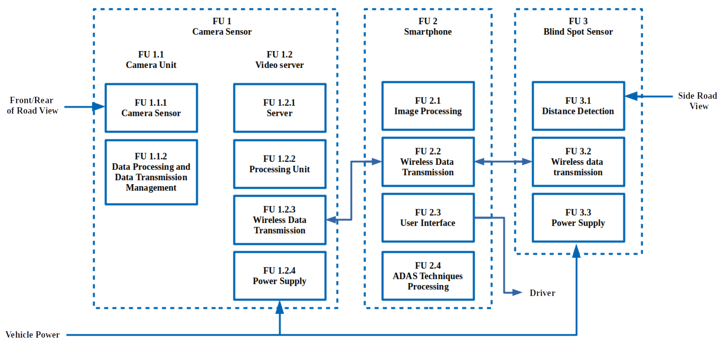
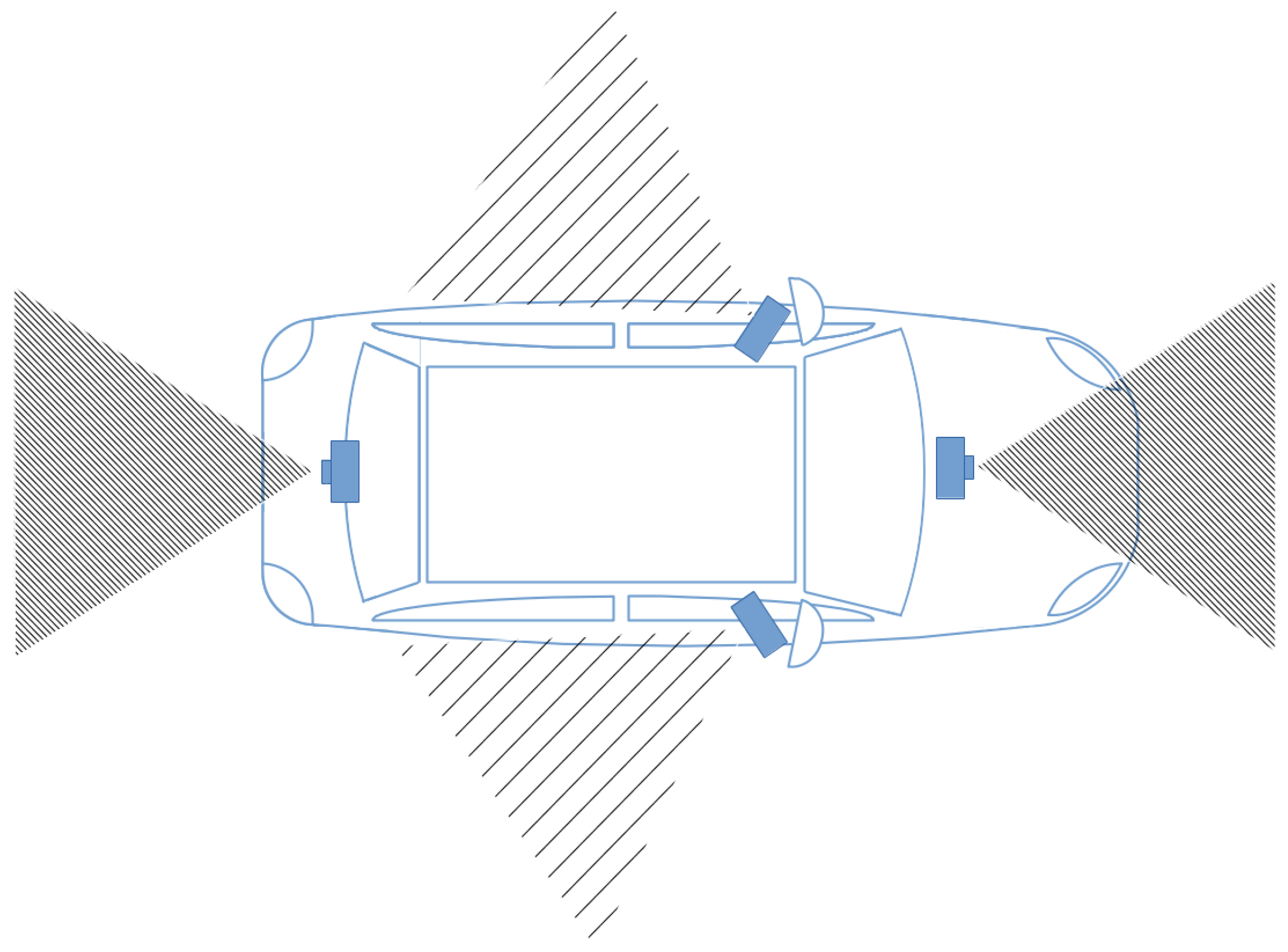
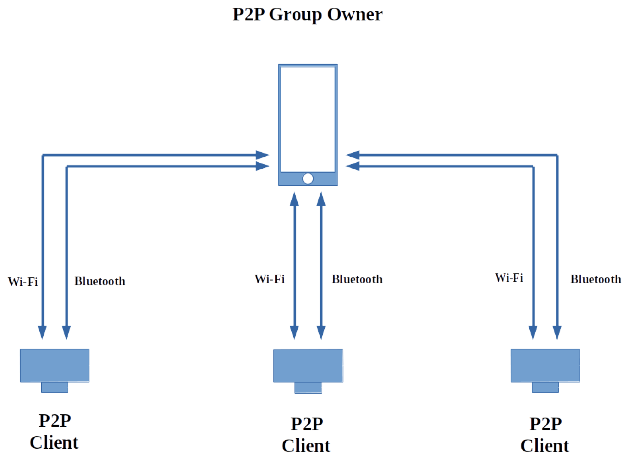
2.1. Intra-Vehicular Wireless Multimedia Sensor Network
2.1.1. Network Topology
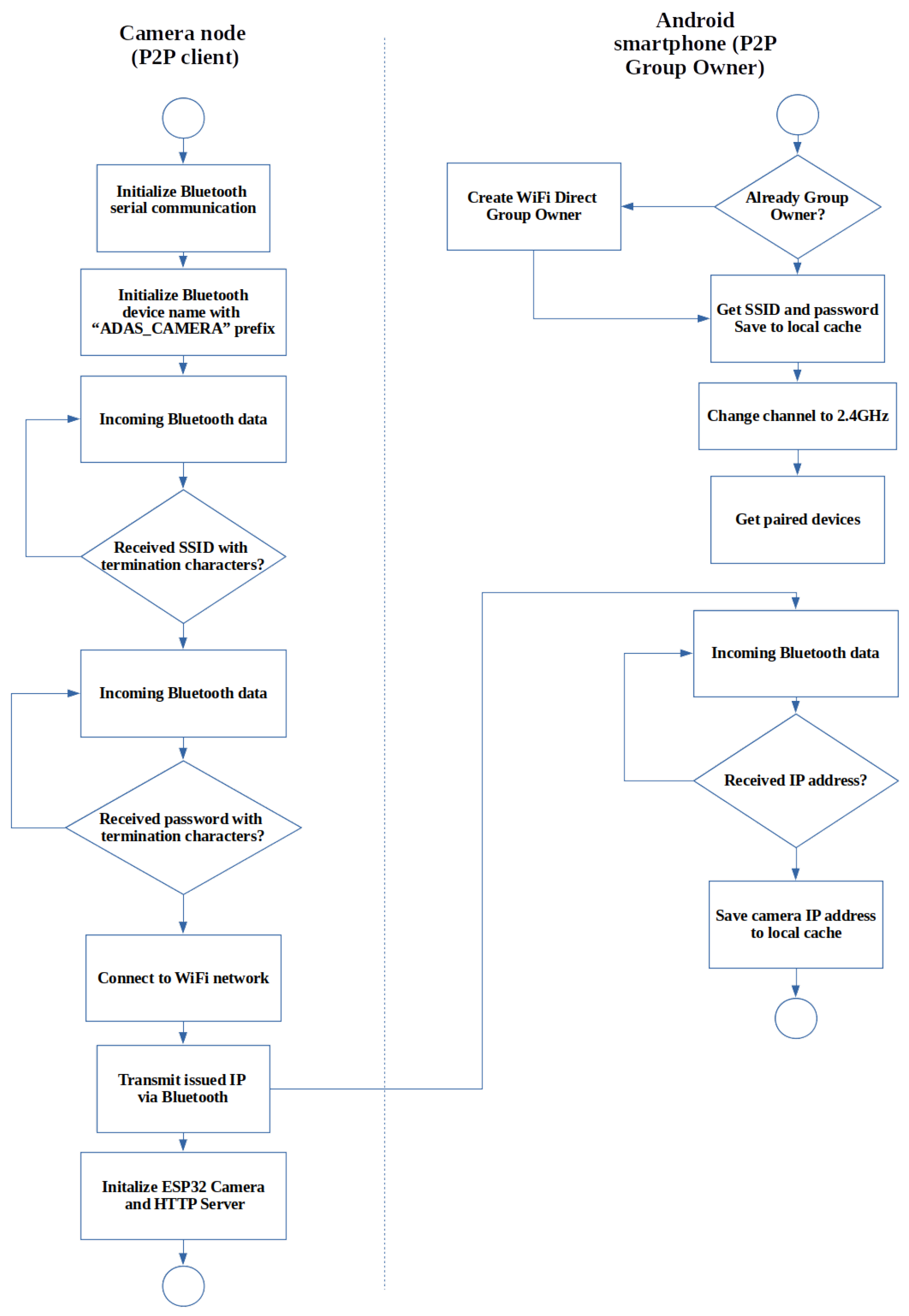
2.1.2. Bluetooth Communication
2.1.3. Wi-Fi Communication
2.1.4. Video Streaming
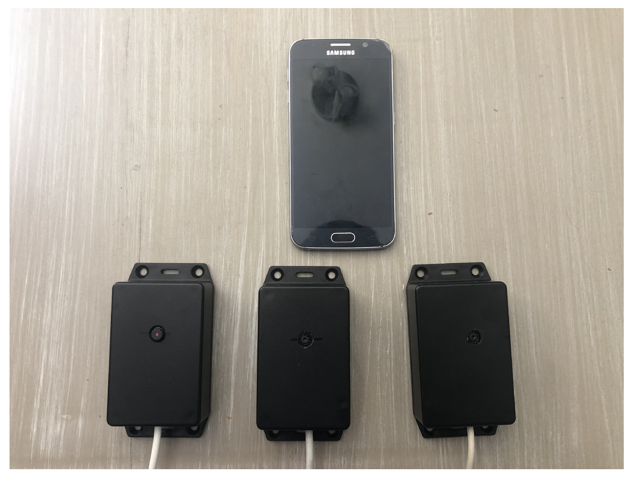
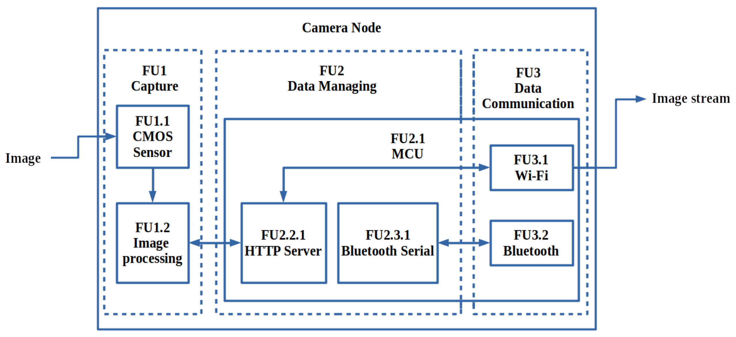
2.1.5. Camera Node
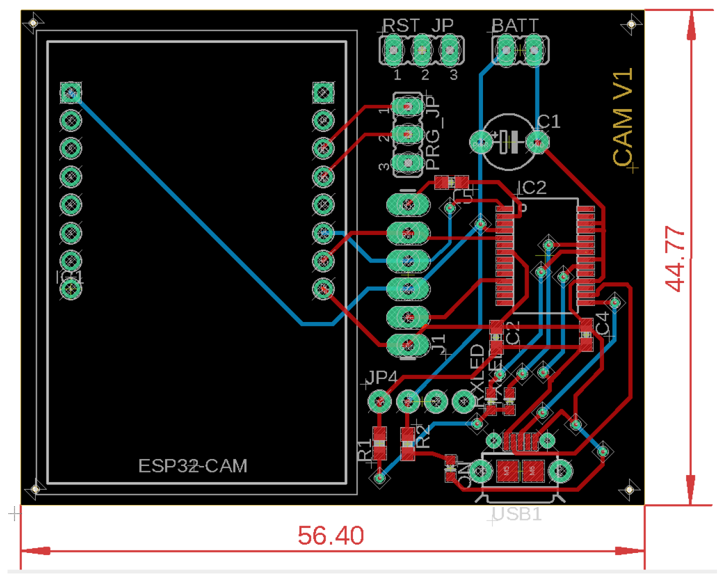
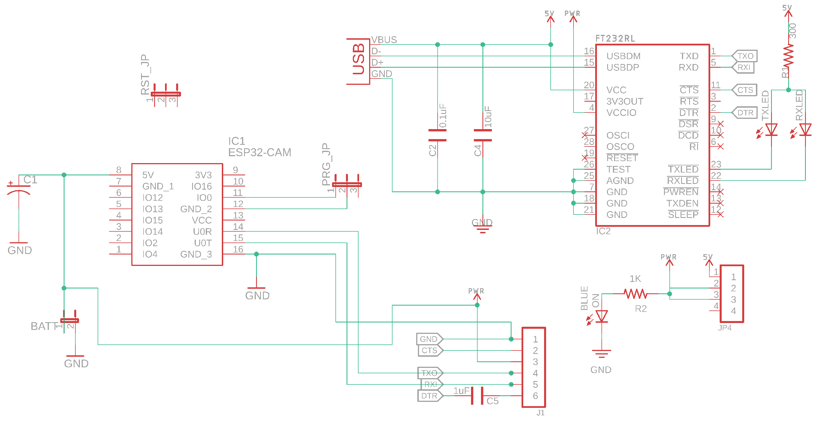
2.1.6. Design Schematics and PCB Layouts
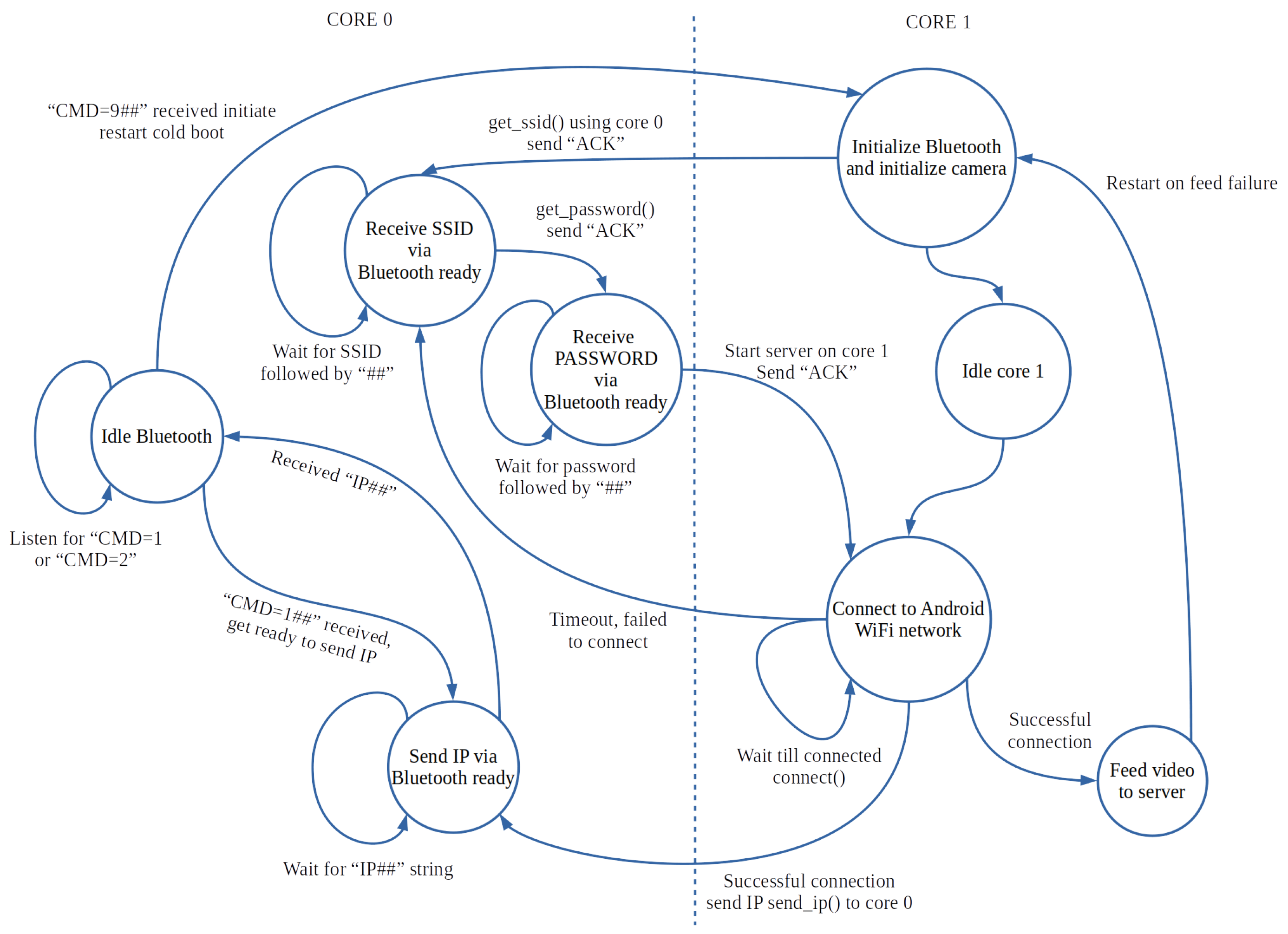
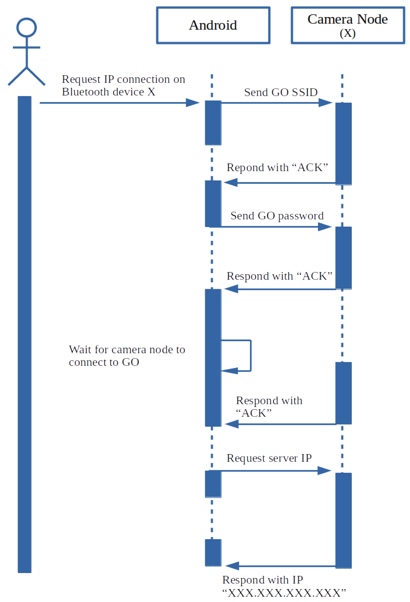
2.1.7. Camera Node Embedded Logic
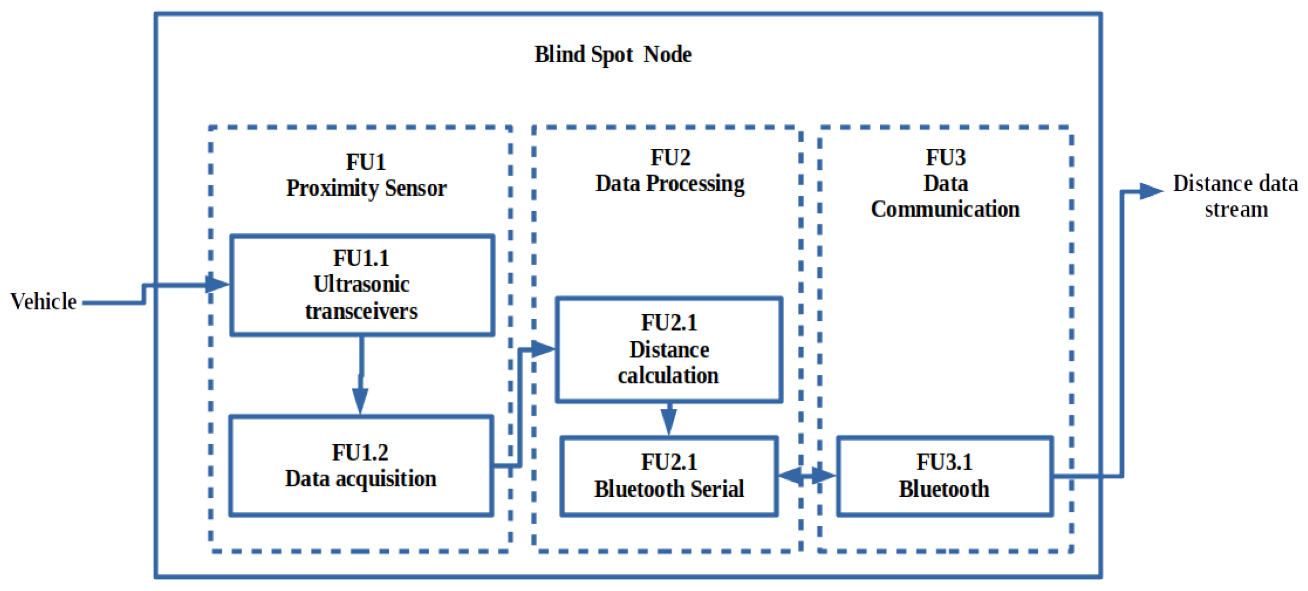
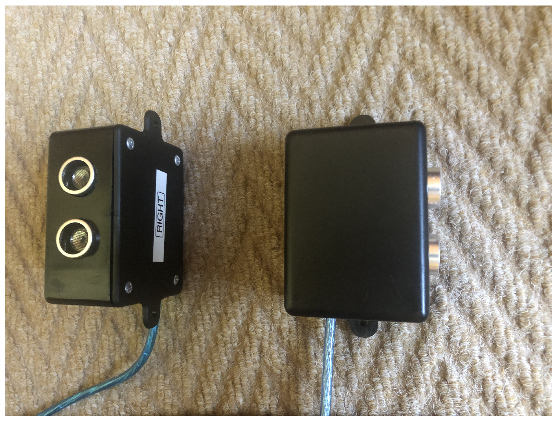
2.1.8. Blind Spot Node
2.2. Smartphone-Based ADAS
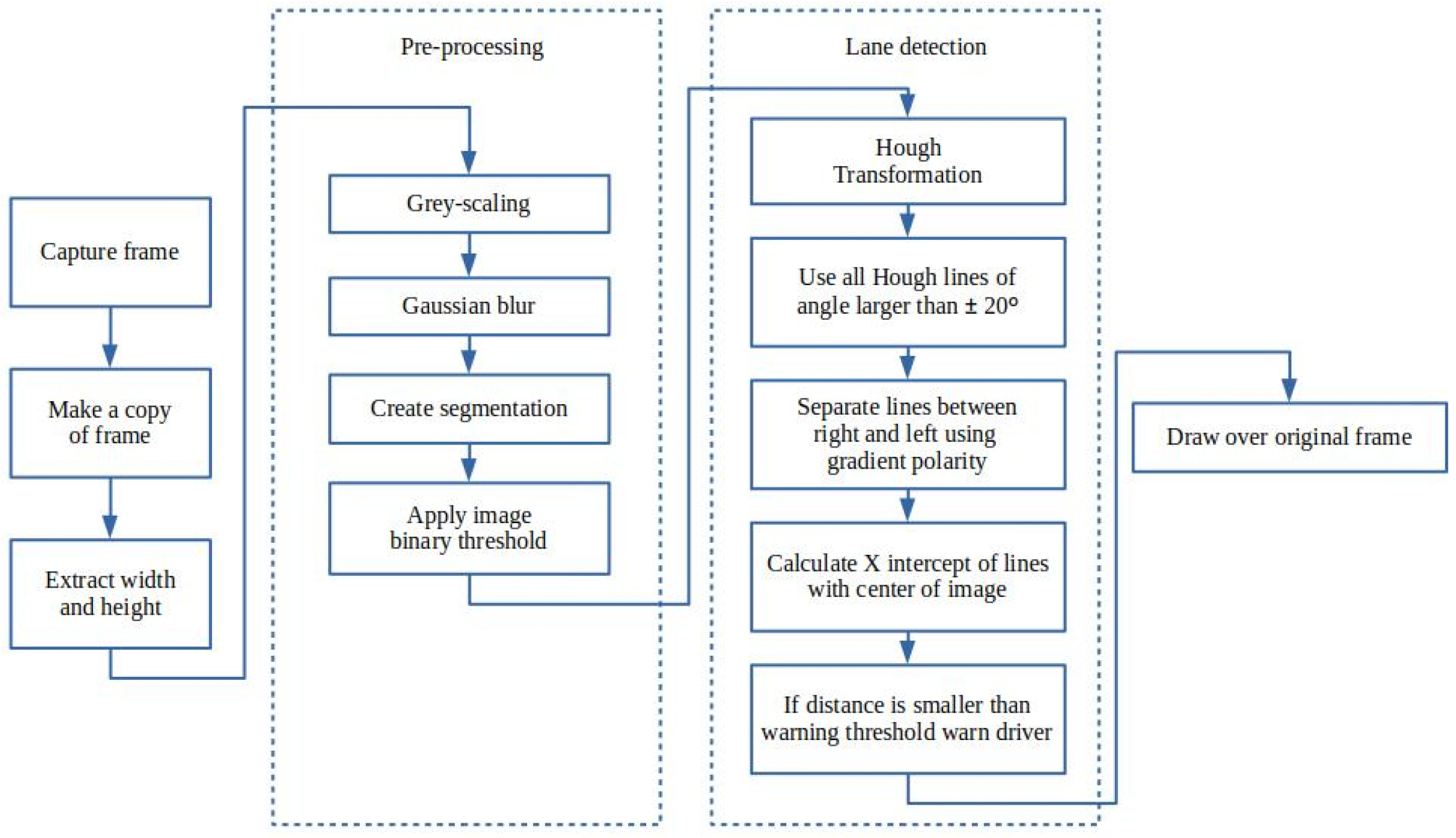
2.2.1. Lane Detection
2.2.2. Collision Detection
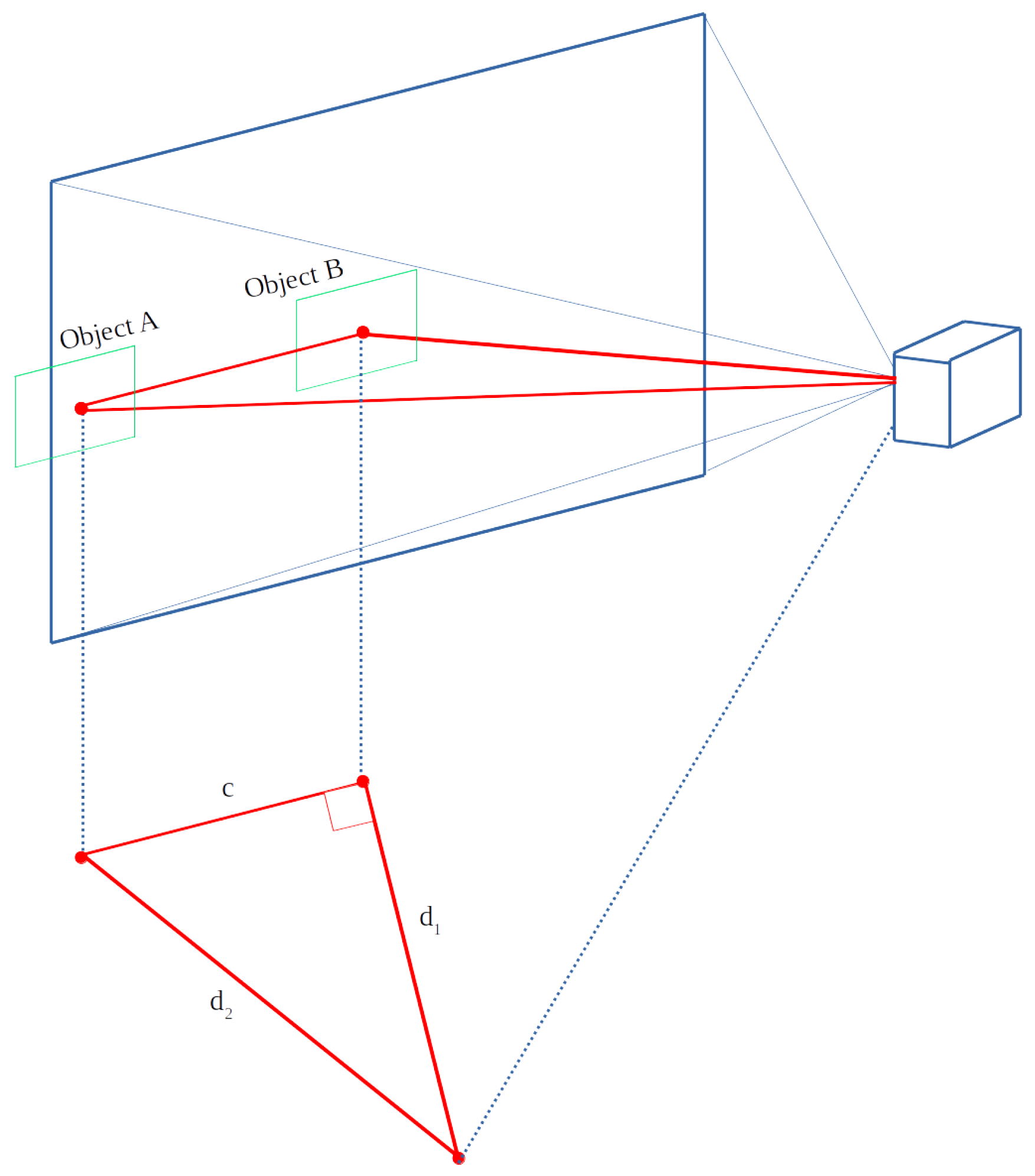
2.2.3. Distance Estimation
3. Results
3.1. Simulated Environment
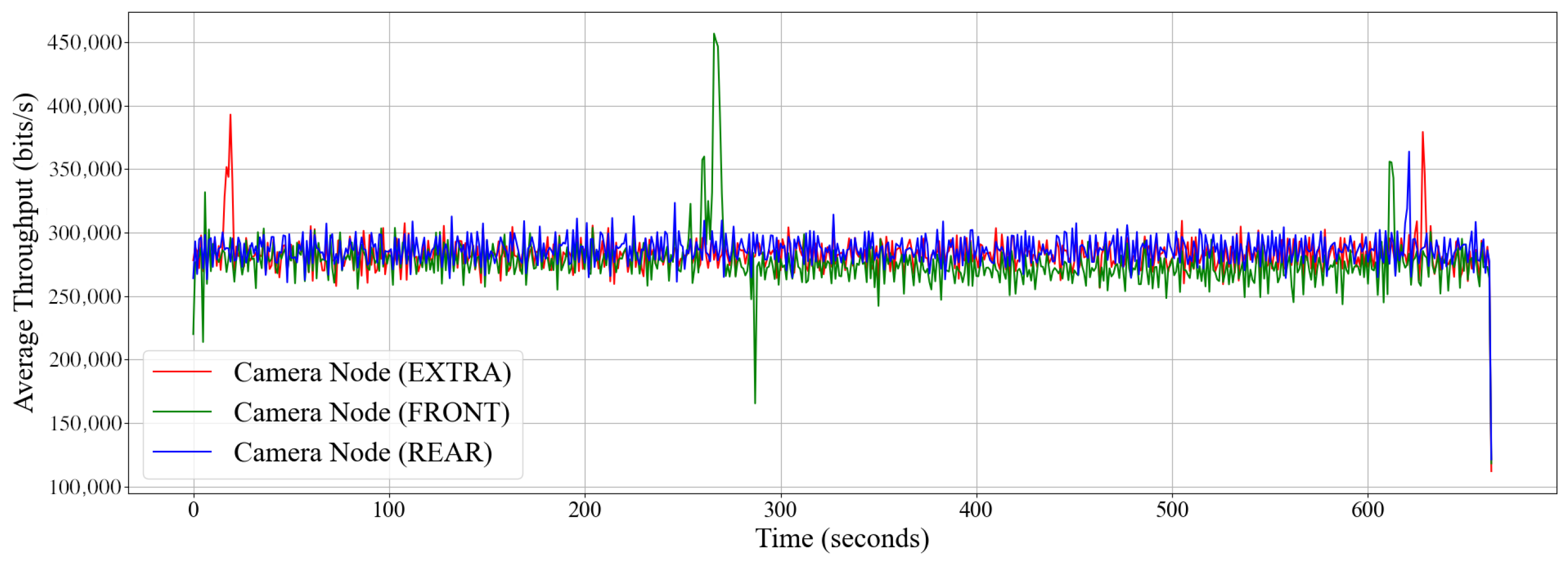
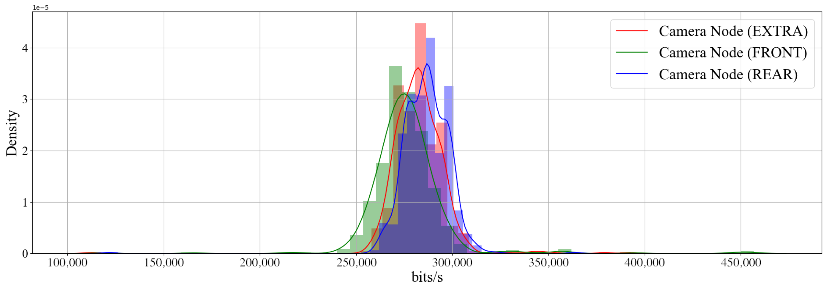
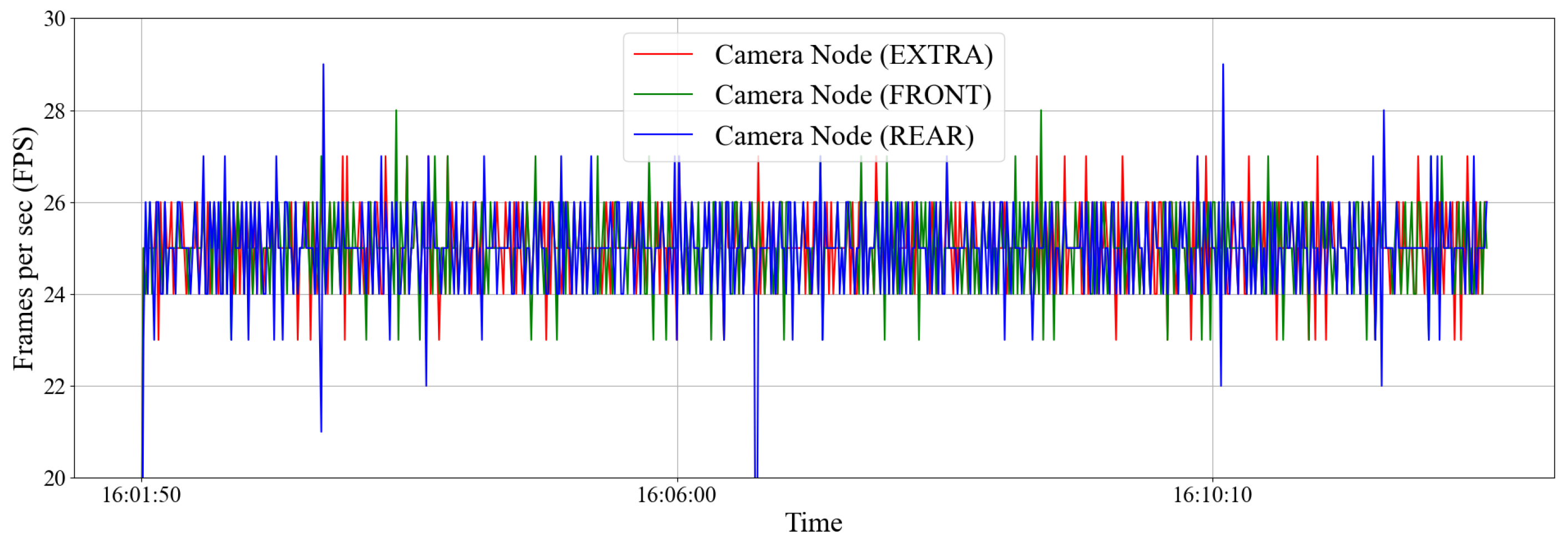
3.2. Intra-Vehicle Environment
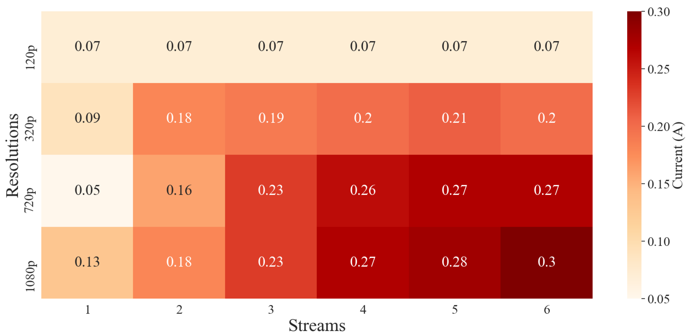
3.3. Android Battery Consumption
3.4. Testing Environment
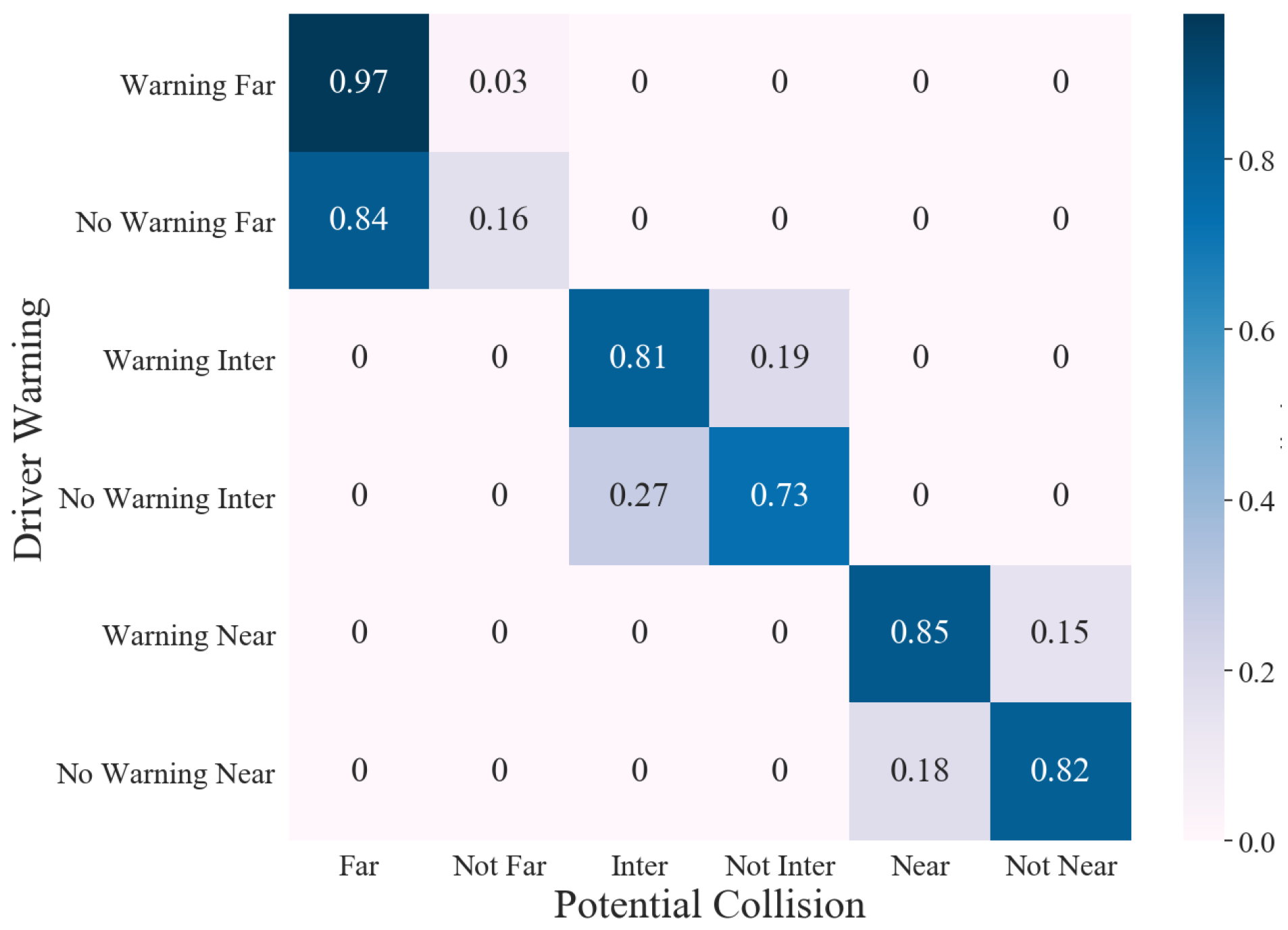
3.4.1. Collision Avoidance
3.4.2. Distance Detection
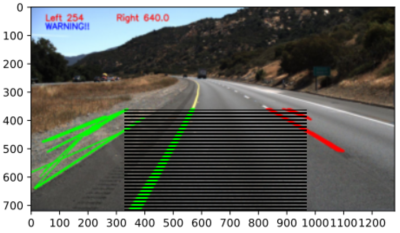
3.4.3. Lane Detection
3.4.4. Blind Spot Detection
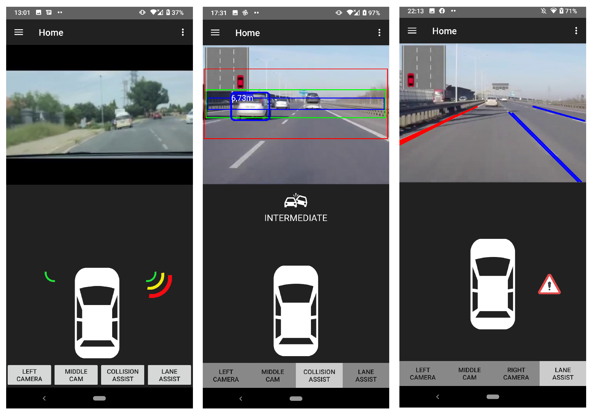
3.5. Android Application
4. Conclusions
Author Contributions
Funding
Institutional Review Board Statement
Informed Consent Statement
Data Availability Statement
Conflicts of Interest
Abbreviations
| ACC | autonomous cruise control |
| ADAS | advanced driver-assistance system(s) |
| ADRT | acceleration and deceleration time |
| BLE | Bluetooth Low Energy |
| CAN | controller area network(s) |
| CMOS | complementary metal-oxide semiconductor |
| CNN | convolutional neural network(s) |
| ECU | electronic control unit |
| FCA | forward collision avoidance |
| IVWSN | intra-vehicular wireless sensor network |
| LBP | local binary patterns |
| MOST | media-oriented system transport |
| SBZA | side blind zone alert |
| UWB | ultra-wideband |
| UUID | universally unique identifier |
| WMSN | wireless multimedia sensor network |
| YOLO | you only look once |
References
- Liu, F.; Sparbert, J.; Stiller, C. IMMPDA vehicle tracking system using asynchronous sensor fusion of radar and vision. In Proceedings of the 2008 IEEE Intelligent Vehicles Symposium, Eindhoven, The Netherlands, 4–6 June 2008; pp. 168–173. [Google Scholar]
- Wei, P.; Cagle, L.; Reza, T.; Ball, J.; Gafford, J. LiDAR and camera detection fusion in a real-time industrial multi-sensor collision avoidance system. Electronics 2018, 7, 84. [Google Scholar] [CrossRef] [Green Version]
- Sole, A.; Mano, O.; Stein, G.P.; Kumon, H.; Tamatsu, Y.; Shashua, A. Solid or not solid: Vision for radar target validation. In Proceedings of the IEEE Intelligent Vehicles Symposium, Parma, Italy, 14–17 June 2004; pp. 819–824. [Google Scholar]
- Coue, C.; Fraichard, T.; Bessiere, P.; Mazer, E. Multi-sensor data fusion using Bayesian programming: An automotive application. In Proceedings of the Intelligent Vehicle Symposium, Versailles, France, 17–21 June 2002; Volume 2, pp. 442–447. [Google Scholar] [CrossRef]
- Bhoraskar, R.; Vankadhara, N.; Raman, B.; Kulkarni, P. Wolverine: Traffic and road condition estimation using smartphone sensors. In Proceedings of the 2012 Fourth International Conference on Communication Systems and Networks (COMSNETS 2012), Bangalore, India, 3–7 January 2012; pp. 1–6. [Google Scholar]
- Fazeen, M.; Gozick, B.; Dantu, R.; Bhukhiya, M. Safe driving using mobile phones. IEEE Trans. Intell. Transp. Syst. 2012, 13, 1462–1468. [Google Scholar] [CrossRef]
- Chaovalit, P.; Saiprasert, C.; Pholprasit, T. A method for driving event detection using SAX on smartphone sensors. In Proceedings of the 2013 13th International Conference on ITS Telecommunications (ITST), Tampere, Finland, 5–7 November 2013; pp. 450–455. [Google Scholar]
- Mohan, P.; Padmanabhan, V.N.; Ramjee, R. Nericell: Using mobile smartphones for rich monitoring of road and traffic conditions. In Proceedings of the 6th ACM Conference on Embedded Network Sensor Systems, Raleigh, NC, USA, 5–7 November 2008; pp. 357–358. [Google Scholar]
- Romera, E.; Bergasa, L.M.; Arroyo, R. A Real-Time Multi-scale Vehicle Detection and Tracking Approach for Smartphones. In Proceedings of the 2015 IEEE 18th International Conference on Intelligent Transportation Systems, Gran Canaria, Spain, 15–18 September 2015; pp. 1298–1303. [Google Scholar] [CrossRef]
- You, C.W.; Lane, N.D.; Chen, F.; Wang, R.; Chen, Z.; Bao, T.J.; Montes-de Oca, M.; Cheng, Y.; Lin, M.; Torresani, L. Carsafe app: Alerting drowsy and distracted drivers using dual cameras on smartphones. In Proceedings of the 11th Annual International Conference on Mobile Systems, Applications, and Services, Taipei, Taiwan, 25–28 June 2013; pp. 13–26. [Google Scholar]
- Petrovai, A.; Danescu, R.; Nedevschi, S. A stereovision based approach for detecting and tracking lane and forward obstacles on mobile devices. In Proceedings of the 2015 IEEE Intelligent Vehicles Symposium (IV), Seoul, Korea, 28 June–1 July 2015; pp. 634–641. [Google Scholar]
- Viola, P.; Jones, M. Rapid object detection using a boosted cascade of simple features. In Proceedings of the 2001 IEEE Computer Society Conference on Computer Vision and Pattern Recognition, Kauai, HI, USA, 8–14 December 2001; Volume 1. [Google Scholar]
- Bhandari, R.; Nambi, A.U.; Padmanabhan, V.N.; Raman, B. DeepLane: Camera-assisted GPS for driving lane detection. In Proceedings of the 5th Conference on Systems for Built Environments, Shenzen, China, 7–8 November 2018; pp. 73–82. [Google Scholar]
- Girshick, R.; Donahue, J.; Darrell, T.; Malik, J. Rich feature hierarchies for accurate object detection and semantic segmentation. In Proceedings of the IEEE Conference on Computer Vision and Pattern Recognition, Columbus, OH, USA, 23–28 June 2014; pp. 580–587. [Google Scholar]
- Girshick, R. Fast R-CNN. In Proceedings of the IEEE International Conference on Computer Vision, Santiago, Chile, 7–13 December 2015; pp. 1440–1448. [Google Scholar]
- Ren, S.; He, K.; Girshick, R.; Sun, J. Faster R-CNN: Towards Real-Time Object Detection with Region Proposal Networks. IEEE Trans. Pattern Anal. Mach. Intell. 2017, 39, 1137–1149. [Google Scholar] [CrossRef] [PubMed] [Green Version]
- Redmon, J.; Divvala, S.; Girshick, R.; Farhadi, A. You only look once: Unified, real-time object detection. In Proceedings of the IEEE Conference on Computer Vision and Pattern Recognition, Las Vegas, NV, USA, 27–30 June 2016; pp. 779–788. [Google Scholar]
- Howard, A.G.; Zhu, M.; Chen, B.; Kalenichenko, D.; Wang, W.; Weyand, T.; Andreetto, M.; Adam, H. Mobilenets: Efficient convolutional neural networks for mobile vision applications. arXiv 2017, arXiv:1704.04861. [Google Scholar]
- Aly, H.; Basalamah, A.; Youssef, M. Lanequest: An accurate and energy-efficient lane detection system. In Proceedings of the 2015 IEEE International Conference on Pervasive Computing and Communications (PerCom), St. Louis, MO, USA, 23–27 March 2015; pp. 163–171. [Google Scholar]
- Lan, M.; Rofouei, M.; Soatto, S.; Sarrafzadeh, M. SmartLDWS: A robust and scalable lane departure warning system for the smartphones. In Proceedings of the 2009 12th International IEEE Conference on Intelligent Transportation Systems, St. Louis, MO, USA, 4–7 October 2009; pp. 1–6. [Google Scholar]
- Tang, S.J.W.; Ng, K.Y.; Khoo, B.H.; Parkkinen, J. Real-time lane detection and rear-end collision warning system on a mobile computing platform. In Proceedings of the 2015 IEEE 39th Annual Computer Software and Applications Conference, Taichung, Taiwan, 1–5 July 2015; Volume 2, pp. 563–568. [Google Scholar]
- Bergasa, L.M.; Almería, D.; Almazán, J.; Yebes, J.J.; Arroyo, R. Drivesafe: An app for alerting inattentive drivers and scoring driving behaviors. In Proceedings of the 2014 IEEE Intelligent Vehicles Symposium Proceedings, Dearborn, MI, USA, 8–11 June 2014; pp. 240–245. [Google Scholar]
- Lin, J.R.; Talty, T.; Tonguz, O.K. A blind zone alert system based on intra-vehicular wireless sensor networks. IEEE Trans. Ind. Informatics 2015, 11, 476–484. [Google Scholar] [CrossRef] [Green Version]
- Wu, B.F.; Huang, H.Y.; Chen, C.J.; Chen, Y.H.; Chang, C.W.; Chen, Y.L. A vision-based blind spot warning system for daytime and nighttime driver assistance. Comput. Electr. Eng. 2013, 39, 846–862. [Google Scholar] [CrossRef]
- Lin, B.F.; Chan, Y.M.; Fu, L.C.; Hsiao, P.Y.; Chuang, L.A.; Huang, S.S.; Lo, M.F. Integrating appearance and edge features for sedan vehicle detection in the blind-spot area. IEEE Trans. Intell. Transp. Syst. 2012, 13, 737–747. [Google Scholar]
- Chen, C.; Chen, Y. Real-time approaching vehicle detection in blind-spot area. In Proceedings of the 2009 12th International IEEE Conference on Intelligent Transportation Systems, St. Louis, MO, USA, 4–7 October 2009; pp. 1–6. [Google Scholar]
- Singh, S.; Meng, R.; Nelakuditi, S.; Tong, Y.; Wang, S. SideEye: Mobile assistant for blind spot monitoring. In Proceedings of the 2014 International Conference on Computing, Networking and Communications (ICNC), Honolulu, HI, USA, 3–6 February 2014; pp. 408–412. [Google Scholar]
- López, A.M.; Imiya, A.; Pajdla, T.; Álvarez, J.M. Computer vision in vehicle technology: Land, sea, and air. In Computer Vision in Vehicle Technology: Land, Sea, and Air, 1st ed.; John Wiley & Sons: London, UK, 2017; pp. 100–117. [Google Scholar]
- Dong, Y.; Hu, Z.; Uchimura, K.; Murayama, N. Driver inattention monitoring system for intelligent vehicles: A review. IEEE Trans. Intell. Transp. Syst. 2010, 12, 596–614. [Google Scholar] [CrossRef]
- Allamehzadeh, A.; de la Parra, J.U.; Hussein, A.; Garcia, F.; Olaverri-Monreal, C. Cost-efficient driver state and road conditions monitoring system for conditional automation. In Proceedings of the 2017 IEEE Intelligent Vehicles Symposium (IV), Los Angeles, CA, USA, 11–14 June 2017; pp. 1497–1502. [Google Scholar]
- Qiao, Y.; Zeng, K.; Xu, L.; Yin, X. A smartphone-based driver fatigue detection using fusion of multiple real-time facial features. In Proceedings of the 2016 13th IEEE Annual Consumer Communications & Networking Conference (CCNC), Las Vegas, NV, USA, 9–12 January 2016; pp. 230–235. [Google Scholar]
- He, J.; Roberson, S.; Fields, B.; Peng, J.; Cielocha, S.; Coltea, J. Fatigue detection using smartphones. J. Ergon. 2013, 3, 1–7. [Google Scholar]
- Lee, B.G.; Chung, W.Y. A smartphone-based driver safety monitoring system using data fusion. Sensors 2012, 12, 17536–17552. [Google Scholar] [CrossRef] [PubMed]
- Smirnov, A.; Kashevnik, A.; Lashkov, I.; Baraniuc, O.; Parfenov, V. Smartphone-based identification of dangerous driving situations: Algorithms and implementation. In Proceedings of the 2016 18th Conference of Open Innovations Association and Seminar on Information Security and Protection of Information Technology (FRUCT-ISPIT), St. Petersburg, Russia, 18–22 April 2016; pp. 306–313. [Google Scholar]
- Tuohy, S.; Glavin, M.; Hughes, C.; Jones, E.; Trivedi, M.; Kilmartin, L. Intra-vehicle networks: A review. IEEE Trans. Intell. Transp. Syst. 2014, 16, 534–545. [Google Scholar] [CrossRef]
- Green, R.J.; Rihawi, Z.; Mutalip, Z.A.; Leeson, M.S.; Higgins, M.D. Networks in automotive systems: The potential for optical wireless integration. In Proceedings of the 2012 14th International Conference on Transparent Optical Networks (ICTON), Coventry, UK, 2–5 July 2012; pp. 1–4. [Google Scholar]
- Iturri, P.L.; Aguirre, E.; Azpilicueta, L.; Garate, U.; Falcone, F. ZigBee radio channel analysis in a complex vehicular environment [wireless corner]. IEEE Antennas Propag. Mag. 2014, 56, 232–245. [Google Scholar] [CrossRef]
- Rahman, M.A. Design of wireless sensor network for intra-vehicular communications. In International Conference on Wired/Wireless Internet Communications; Springer: Cham, Switzerland, 2014; pp. 29–40. [Google Scholar]
- Rahman, M.A.; Ali, J.; Kabir, M.N.; Azad, S. A performance investigation on IoT enabled intra-vehicular wireless sensor networks. Int. J. Automot. Mech. Eng. 2017, 14, 3970–3984. [Google Scholar] [CrossRef]
- Lee, J.S.; Su, Y.W.; Shen, C.C. A comparative study of wireless protocols: Bluetooth, UWB, ZigBee, and Wi-Fi. In Proceedings of the IECON 2007-33rd Annual Conference of the IEEE Industrial Electronics Society, Taipei, Taiwan, 5–8 November 2007; pp. 46–51. [Google Scholar]
- Akyildiz, I.F.; Melodia, T.; Chowdhury, K.R. A survey on wireless multimedia sensor networks. Comput. Netw. 2007, 51, 921–960. [Google Scholar] [CrossRef]
- Kato, T.; Ninomiya, Y.; Masaki, I. An obstacle detection method by fusion of radar and motion stereo. IEEE Trans. Intell. Transp. Syst. 2002, 3, 182–188. [Google Scholar] [CrossRef]
- Zhang, F.; Clarke, D.; Knoll, A. Vehicle detection based on LiDAR and camera fusion. In Proceedings of the 17th International IEEE Conference on Intelligent Transportation Systems (ITSC), Qingdao, China, 8–11 October 2014; pp. 1620–1625. [Google Scholar]
- Khan, J. Using ADAS sensors in implementation of novel automotive features for increased safety and guidance. In Proceedings of the 2016 3rd International Conference on Signal Processing and Integrated Networks (SPIN), Noida, India, 11–12 February 2016; pp. 753–758. [Google Scholar]
- Mahapatra, R.; Kumar, K.V.; Khurana, G.; Mahajan, R. Ultra sonic sensor based blind spot accident prevention system. In Proceedings of the 2008 International Conference on Advanced Computer Theory and Engineering, Phuket, Thailand, 20–22 December 2008; pp. 992–995. [Google Scholar]
- Akhlaq, M.; Sheltami, T.R.; Helgeson, B.; Shakshuki, E.M. Designing an integrated driver assistance system using image sensors. J. Intell. Manuf. 2012, 23, 2109–2132. [Google Scholar] [CrossRef]
- Wi-Fi Alliance. Wi-Fi Peer-to-Peer (P2P) Technical Specification Version 1.7. 2016. Available online: https://documents.pub/document/wi-fi-p2p-technical-specification-technical-specification-version-17-this-document.html (accessed on 26 October 2021).
- “Bluetooth Overview-Key Classes and Interfaces”. Android Developers Documentation Guides. Available online: https://developer.android.com/guide/topics/connectivity/bluetooth (accessed on 26 October 2021).
- “HTTP-Hypertext Transfer Protocol”. W3C Architecture Domain. Available online: https://www.w3.org/Protocols/ (accessed on 26 October 2021).
- Ultrasonic Ranging Module HC-SR04. 2013. Available online: https://cdn.sparkfun.com/datasheets/Sensors/Proximity/HCSR04.pdf (accessed on 26 October 2021).
- “OpenCV Releases”. OpenCV.org. Available online: https://opencv.org/releases (accessed on 26 October 2021).
- Behrendt, K. Boxy Vehicle Detection in Large Images. In Proceedings of the IEEE International Conference on Computer Vision Workshops, Seoul, Korea, 27–28 October 2019; pp. 840–846. [Google Scholar]


| Resolution | 1 Stream | 2 Streams | 3 Streams | 4 Streams | 5 Streams | 6 Streams |
|---|---|---|---|---|---|---|
| 120p | 522.22 | 265.91 | 175.64 | 131.91 | 107.31 | 87.73 |
| 320p | 47.02 | 38.90 | 22.76 | 20.35 | 14.64 | 13.47 |
| 720p | 3.57 | 2.65 | 2.43 | 2.02 | 1.71 | 1.52 |
| 1080p | 1.04 | 1.00 | 1.00 | 1.00 | 1.00 | 1.00 |
| Test Interval | Actual Distance (cm) | Calculated Distance (cm) | Error (cm) | Accuracy % |
|---|---|---|---|---|
| 3 metre mark | 300 | 362 | 62 | 83% |
| 6 metre mark | 600 | 604 | 4 | 99% |
| 9 metre mark | 900 | 902 | 2 | 100% |
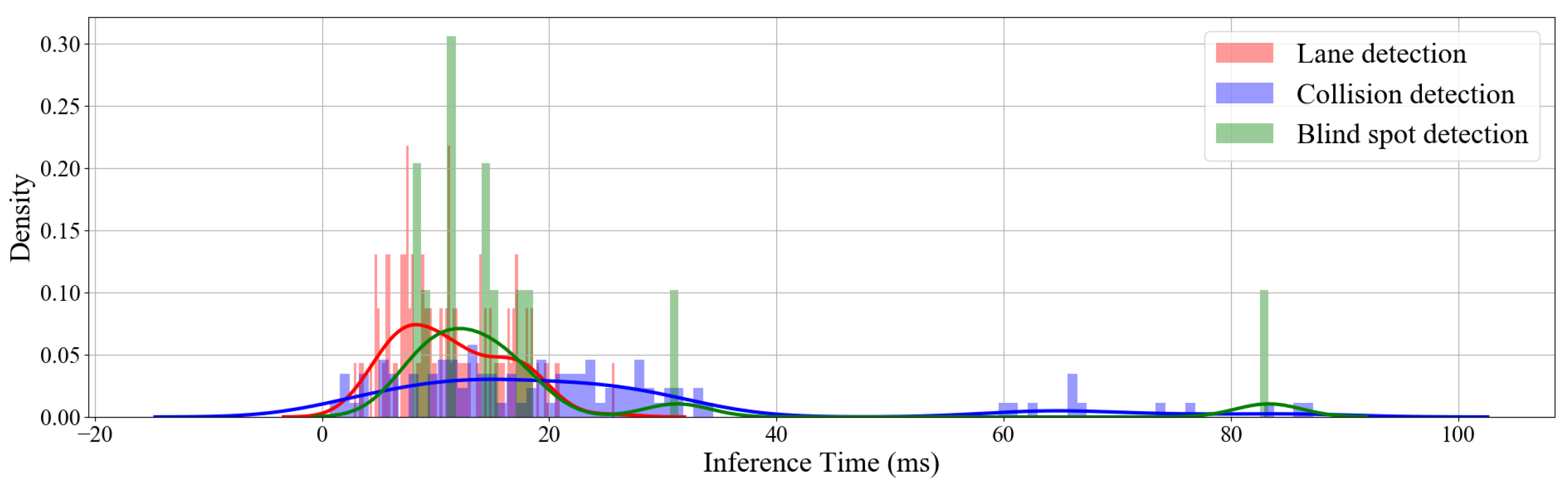
| Delay Type | FPS | Average (ms) | Standard Deviation (ms) |
|---|---|---|---|
| Collision detection | 44.1 | 22.7 | 20.1 |
| Lane detection | 82.6 | 12.1 | 4.8 |
| Blind spot detection | 65.7 | 15.2 | 25.4 |
| Camera node (including network) | 25.6 | 39 | 1.1 |
Publisher’s Note: MDPI stays neutral with regard to jurisdictional claims in published maps and institutional affiliations. |
© 2022 by the authors. Licensee MDPI, Basel, Switzerland. This article is an open access article distributed under the terms and conditions of the Creative Commons Attribution (CC BY) license (https://creativecommons.org/licenses/by/4.0/).
Share and Cite
Fourie, C.M.; Myburgh, H.C. An Intra-Vehicular Wireless Multimedia Sensor Network for Smartphone-Based Low-Cost Advanced Driver-Assistance Systems. Sensors 2022, 22, 3026. https://doi.org/10.3390/s22083026
Fourie CM, Myburgh HC. An Intra-Vehicular Wireless Multimedia Sensor Network for Smartphone-Based Low-Cost Advanced Driver-Assistance Systems. Sensors. 2022; 22(8):3026. https://doi.org/10.3390/s22083026
Chicago/Turabian StyleFourie, Christiaan M., and Hermanus Carel Myburgh. 2022. "An Intra-Vehicular Wireless Multimedia Sensor Network for Smartphone-Based Low-Cost Advanced Driver-Assistance Systems" Sensors 22, no. 8: 3026. https://doi.org/10.3390/s22083026