
A Review of MEMS Vibrating Gyroscopes and Their Reliability Issues in Harsh Environments


Abstract
:1. Introduction
2. Fundamentals of Vibrating Gyroscopes
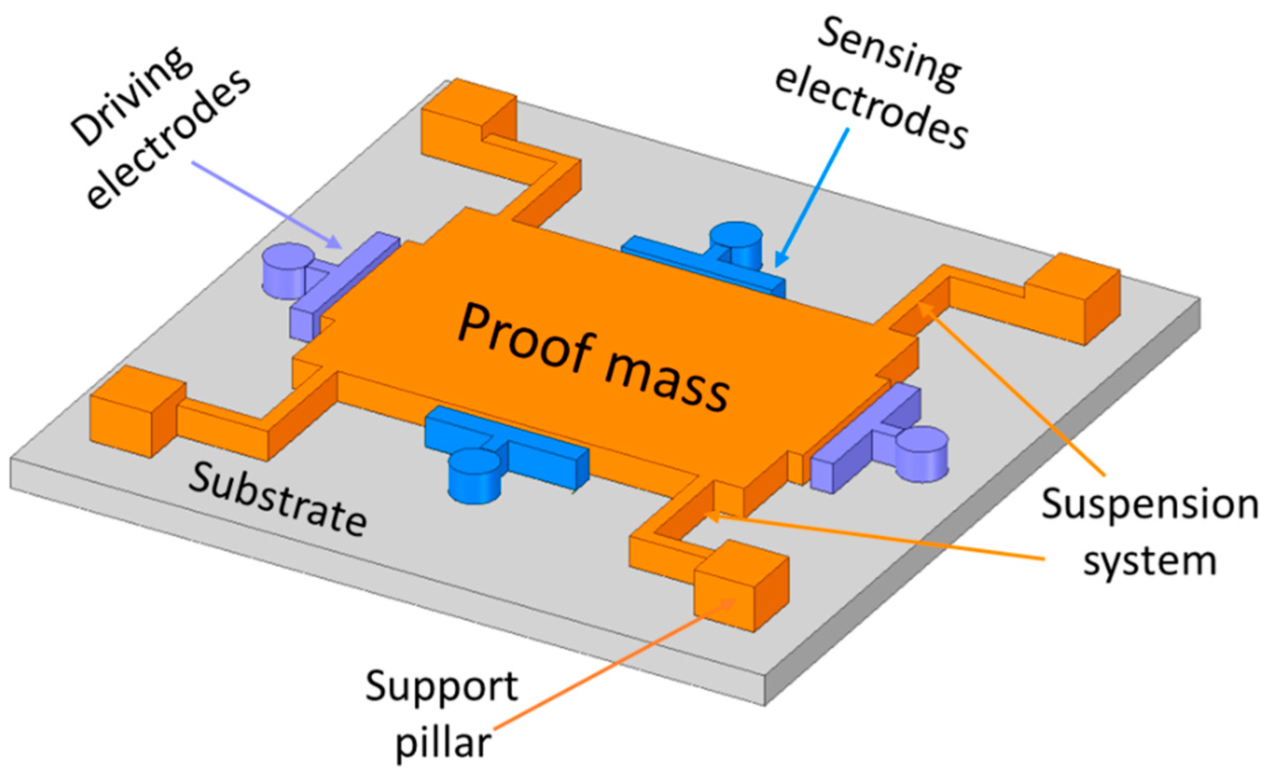
2.1. Basic Architecture
2.2. Drive-Mode Operation
2.3. Sense-Mode Operation
2.4. Mode-Matching Effectiveness
3. Micro-Electromechanical Systems (MEMS) Vibrating Gyroscopes
3.1. Gimbal Gyroscopes
3.2. Tuning Fork Gyroscopes
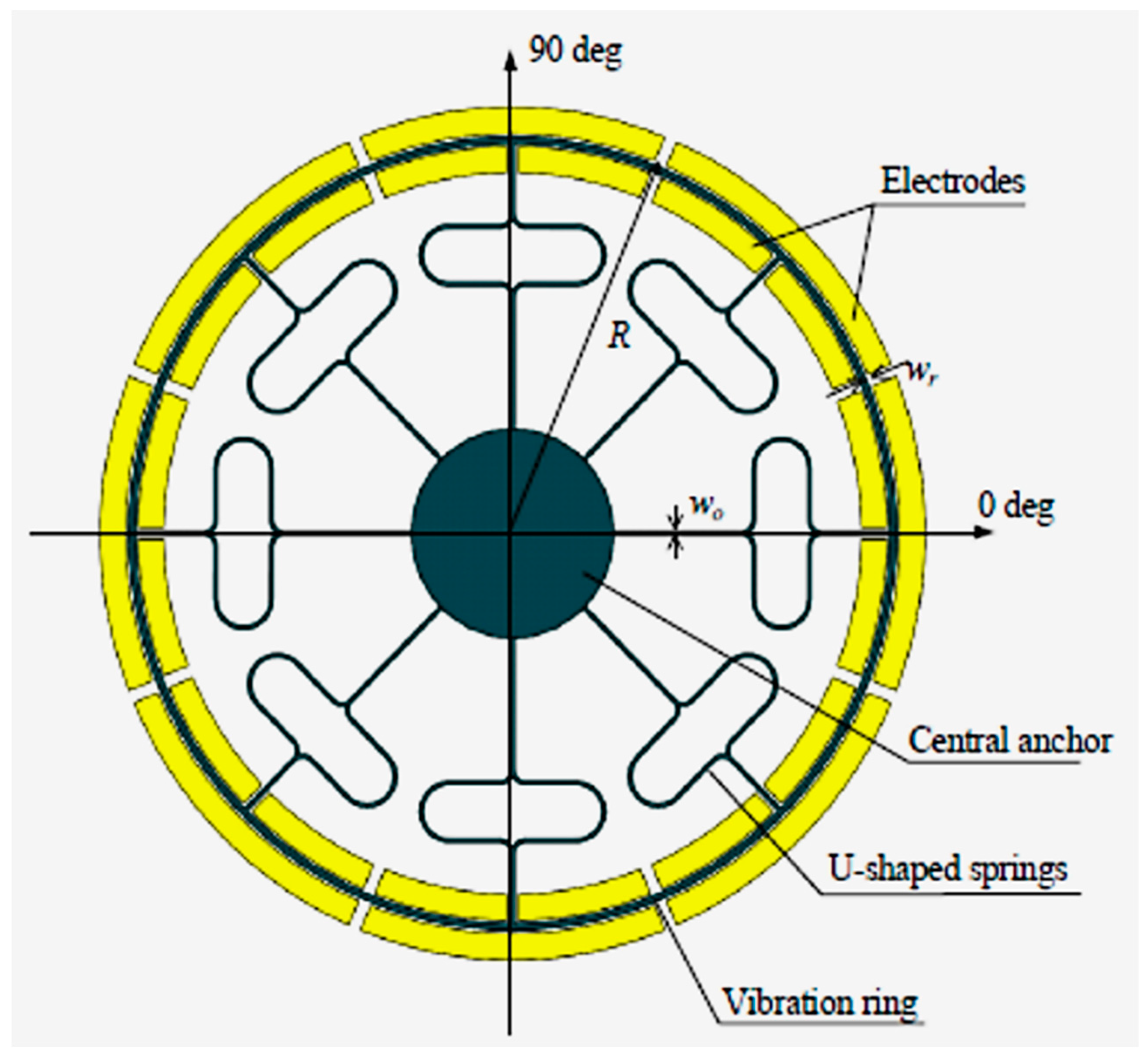
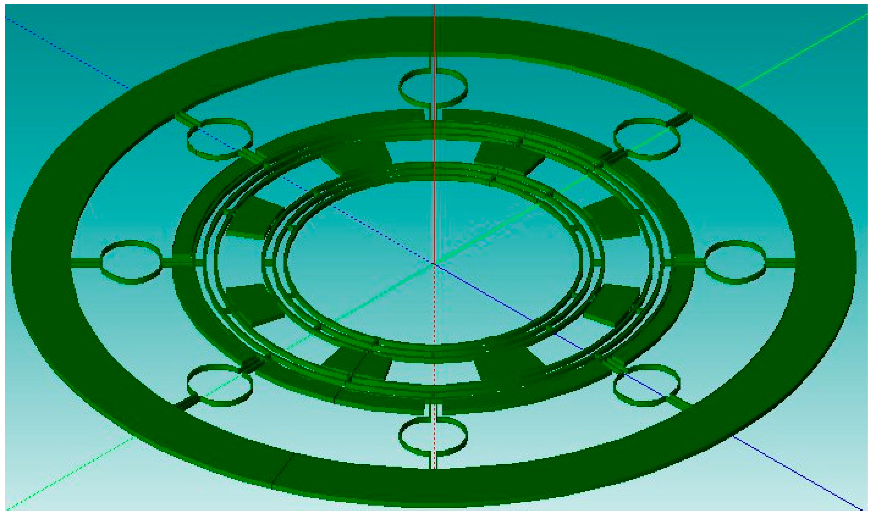
3.3. Vibrating Ring Gyroscopes
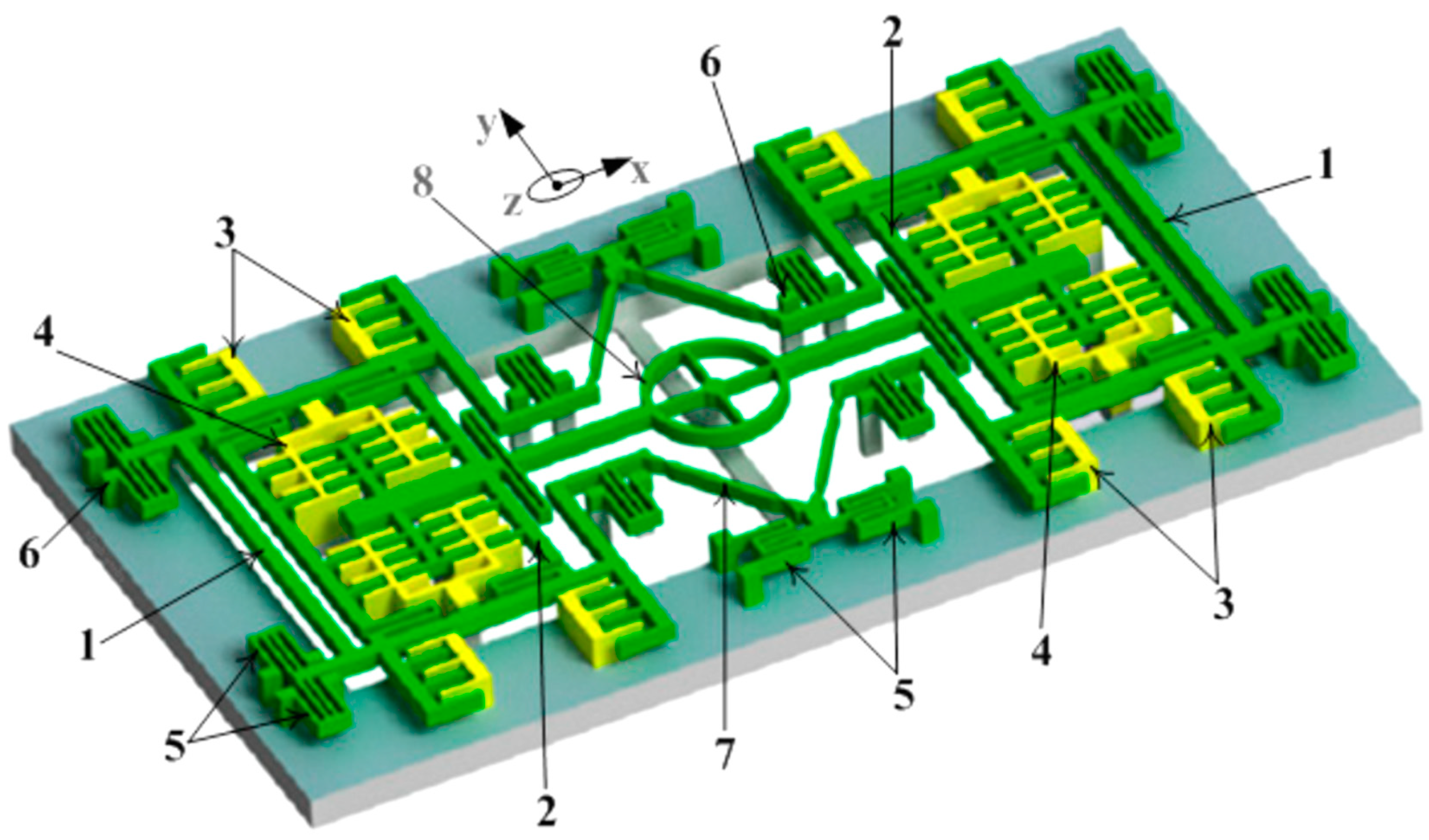
3.4. Multi-Axis Gyroscopes
4. Reliability Issues
4.1. Temperature Characteristics
4.2. Mode Mismatch
5. Conclusions
Author Contributions
Funding
Institutional Review Board Statement
Informed Consent Statement
Data Availability Statement
Acknowledgments
Conflicts of Interest
Nomenclature
| FD | driving force |
| FS | sensing force |
| FC | Coriolis force |
| m | inertial mass |
| x | displacement into driving motion |
| y | displacement into sensing motion |
| c | damping coefficient |
| k | stiffness constant |
| external rotation rate | |
| natural frequency | |
| damping factor | |
| F0 | initial force |
| initial displacement | |
| phase angle | |
| driving mass | |
| driving spring stiffness constant | |
| driving damping constant | |
| Coriolis mass | |
| driving frequency | |
| sensing mass | |
| sensing spring stiffness constant | |
| sensing damping constant | |
| SU-8 | epoxy-based negative photoresist |
| UV LIGA | ultra violet lithography galvanoforming aboforming |
| FEA | finite element analysis |
References
- Turner, G. History of Gyroscopes. 2004. Available online: http://www.gyroscopes.org/history.asp (accessed on 1 August 2022).
- Tazartes, D. (Ed.) An historical perspective on inertial navigation systems. In Proceedings of the 2014 International Symposium on Inertial Sensors and Systems (ISISS), Laguna Beach, CA, USA, 25–26 February 2014; IEEE: Piscataway, NJ, USA, 2014. [Google Scholar]
- Bergh, R.; Lefevre, H.; Shaw, H. An overview of fiber-optic gyroscopes. J. Lightwave Technol. 1984, 2, 91–107. [Google Scholar] [CrossRef]
- Seeger, J.; Lim, M.; Nasiri, S. (Eds.) Development of High-Performance High-Volume Consumer MEMS Gyroscopes; Solid-State Sensors, Actuators, and Microsystems Workshop: Hilton Head Island, SC, USA, 2010. [Google Scholar]
- Mohammed, Z.; Gill, W.; Rasras, M. Modelling optimization and characterization of inertial sensors. In Nanoscale Semiconductor Devices, MEMS, and Sensors: Outlook and Challenges; Springer: Berlin/Heidelberg, Germany, 2017. [Google Scholar]
- De Groote, F.; Vandevyvere, S.; Vanhevel, F.; Orban de Xivry, J.-J. Validation of a smartphone embedded inertial measurement unit for measuring postural stability in older adults. Gait Posture 2021, 84, 17–23. [Google Scholar] [CrossRef] [PubMed]
- Mohammed, Z.; Gill, W.A.; Rasras, M.J.I.S.L. Double-comb-finger design to eliminate cross-axis sensitivity in a dual-axis accelerometer. IEEE Sens. Lett. 2017, 1, 1–4. [Google Scholar] [CrossRef]
- Ren, D.; Yan, M.; You, Z.J.T.; Technologies, M. Principle and research progress of resonant MEMS magnetometer. Transducer Microsyst. Technol. 2007, 26, 10–12. [Google Scholar]
- Wendel, J.; Meister, O.; Schlaile, C.; Trommer, G.F. An integrated GPS/MEMS-IMU navigation system for an autonomous helicopter. Aerosp. Sci. Technol. 2006, 10, 527–533. [Google Scholar] [CrossRef]
- Gaura, E.; Newman, R. Smart MEMS and Sensor Systems; World Scientific: Singapore, 2006. [Google Scholar] [CrossRef]
- Korvink, J.; Paul, O. MEMS: A Practical Guide of Design, Analysis, and Applications; Springer Science & Business Media: Berlin/Heidelberg, Germany, 2010. [Google Scholar]
- Younis, M.I. MEMS Linear and Nonlinear Statics and Dynamics; Springer Science & Business Media: Berlin/Heidelberg, Germany, 2011. [Google Scholar]
- Acar, C.; Shkel, A. MEMS Vibratory Gyroscopes: Structural Approaches to Improve Robustness; Springer Science & Business Media: Berlin/Heidelberg, Germany, 2008. [Google Scholar]
- Acar, C.; Shkel, A.; Costlow, L.; Madni, A. Inherently Robust Micromachined Gyroscopes with 2-DOF Sense-Mode Oscillator. J. Microelectromech. Syst. 2006, 15, 380–387. [Google Scholar] [CrossRef]
- Acar, C.; Shkel, A. An approach for increasing drive-mode bandwidth of MEMS vibratory gyroscopes. J. Microelectromech. Syst. 2005, 14, 520–528. [Google Scholar] [CrossRef]
- Dong, L.; Avanesian, D. Drive-Mode Control for Vibrational MEMS Gyroscopes. IEEE Trans. Ind. Electron. 2008, 56, 956–963. [Google Scholar] [CrossRef]
- Acar, C.; Schofield, A.R.; Trusov, A.A.; Costlow, L.E.; Shkel, A.M. Environmentally robust MEMS vibratory gyroscopes for auto-motive applications. IEEE Sens. J. 2009, 9, 1895–1906. [Google Scholar] [CrossRef]
- Ghisi, A.; Mariani, S. Effect of Imperfections Due to Material Heterogeneity on the Offset of Polysilicon MEMS Structures. Sensors 2019, 19, 3256. [Google Scholar] [CrossRef] [Green Version]
- Ma, Z.; Chen, X.; Jin, X.; Jin, Y.; Zheng, X.; Jin, Z. Effects of Structural Dimension Variation on the Vibration of MEMS Ring-Based Gyroscopes. Micromachines 2021, 12, 1483. [Google Scholar] [CrossRef] [PubMed]
- Behera, A.R.; Shaik, H.; Rao, G.M.; Pratap, R. A Technique for Estimation of Residual Stress and Young’s Modulus of Compressively Stressed Thin Films Using Microfabricated Beams. J. Microelectromech. Syst. 2019, 28, 1039–1054. [Google Scholar] [CrossRef]
- Passaro, V.M.N.; Cuccovillo, A.; Vaiani, L.; De Carlo, M.; Campanella, C.E. Gyroscope Technology and Applications: A Review in the Industrial Perspective. Sensors 2017, 17, 2284. [Google Scholar] [CrossRef] [PubMed]
- Liu, K.; Zhang, W.; Chen, W.; Li, K.; Dai, F.; Cui, F.; Wu, X.; Ma, G.; Xiao, Q. The development of micro-gyroscope technology. J. Microme-Chanics Microeng. 2009, 19, 113001. [Google Scholar] [CrossRef]
- Pistorio, F.; Saleem, M.M.; Somà, A. A Dual-Mass Resonant MEMS Gyroscope Design with Electrostatic Tuning for Frequency Mismatch Compensation. Appl. Sci. 2021, 11, 1129. [Google Scholar] [CrossRef]
- Nguyen, N.M.; Chang, C.-Y.; Pillai, G.; Li, S.-S. Design of piezoelectric MEMS bulk acoustic wave mode-matched gyro-scopes based on support transducer. In Proceedings of the 2021 IEEE 34th International Conference on Micro Electro Mechanical Systems (MEMS), Gainesville, FL, USA, 25–29 January 2021. [Google Scholar]
- Iga, Y.; Kanda, K.; Fujita, T.; Higuchi, K.; Maenaka, K. A design and fabrication of mems gyroscope using PZT thin films. In Proceedings of the 2010 World Automation Congress, Kobe, Japan, 19–23 September 2010. [Google Scholar]
- Yeh, C.; Tsai, J.; Shieh, R.; Tseng, F.; Li, C.; Su, Y. A vertically supported ring-type mems gyroscope utilizing electromag-netic actuation and sensing. In Proceedings of the 2008 IEEE International Conference on Electron Devices and Solid-State Circuits, Hong Kong, China, 8–10 December 2008. [Google Scholar]
- Saqib, M.; Mubasher Saleem, M.; Mazhar, N.; Awan, S.U.; Shahbaz Khan, U. Design and analysis of a high-gain and robust mul-ti-DOF electro-thermally actuated MEMS gyroscope. Micromachines 2018, 9, 577. [Google Scholar] [CrossRef] [PubMed]
- Senkal, D.; Efimovskaya, A.; Shkel, A.M. Minimal realization of dynamically balanced lumped mass WA gyroscope: Dual foucault pendulum. In Proceedings of the 2015 IEEE International Symposium on Inertial Sensors and Systems (ISISS), Hapuna Beach, HI, USA, 23–26 March 2015. [Google Scholar]
- Zhanshe, G.; Fucheng, C.; Boyu, L.; Le, C.; Chao, L.; Ke, S. Research development of silicon MEMS gyroscopes: A review. Microsyst. Technol. 2015, 21, 2053–2066. [Google Scholar] [CrossRef]
- Armenise, M.N.; Ciminelli, C.; Dell’Olio, F.; Passaro, V.M. Advances in Gyroscope Technologies; Springer Science & Business Media: Berlin/Heidelberg, Germany, 2010. [Google Scholar]
- Boxenhorn, B.; Greiff, P. A vibratory micromechanical gyroscope. Guid. Navig. Control. Conf. 1988. [Google Scholar] [CrossRef]
- Greiff, P.; Boxenhorn, B.; King, T.; Niles, L. Silicon monolithic micromechanical gyroscope. In Proceedings of the TRANSDUCERS’91: 1991 International Conference on Solid-State Sensors and Actuators Digest of Technical Papers, San Francisco, CA, USA, 24–27 June 1991. [Google Scholar]
- Greiff, P.; Antkowiak, B.; Campbell, J.; Petrovich, A. Vibrating wheel micromechanical gyro. In Proceedings of the Position, Location and Navigation Symposium-PLANS’96, Atlanta, GA, USA, 22–25 April 1996. [Google Scholar]
- Bernstein, J.; Cho, S.; King, A.; Kourepenis, A.; Maciel, P.; Weinberg, M. A micromachined comb-drive tuning fork rate gyroscope. In Proceedings of the IEEE Micro Electro Mechanical Systems, Fort Lauderdale, FL, USA, 10 February 1993. [Google Scholar]
- Geiger, W.; Folkmer, B.; Merz, J.; Sandmaier, H.; Lang, W. A new silicon rate gyroscope. Sens. Actuators A Phys. 1999, 73, 45–51. [Google Scholar] [CrossRef]
- Maenaka, K.; Ioku, S.; Sawai, N.; Fujita, T.; Takayama, Y. Design, fabrication and operation of MEMS gimbal gyroscope. Sens. Actuators A Phys. 2005, 121, 6–15. [Google Scholar] [CrossRef]
- Jain, A.; Shekhar, C.; Gopal, R. Fabrication of two-gimbal Ni–Fe torsional micro-gyroscope by SU-8 based UV-LIGA process. Microsyst. Technol. 2014, 21, 1479–1487. [Google Scholar] [CrossRef]
- Lee, J.S.; An, B.H.; Mansouri, M.; Al Yassi, H.; Taha, I.; Gill, W.A.; Choi, D.S. MEMS vibrating wheel on gimbal gyroscope with high scale factor. Microsyst. Technol. 2019, 25, 4645–4650. [Google Scholar] [CrossRef]
- Van Vu, T.; Tran, D.Q.; Chu, T.D. Matching mechanical response for a MEMS vibratory tuning fork gyroscope. Microsyst. Technol. 2020, 26, 3865–3874. [Google Scholar] [CrossRef]
- Dong, X.; Huang, Q.; Yang, S.; Huang, Y.; En, Y. Model and experiment of scale factor acceleration sensitivity of MEMS gyroscope in high acceleration environment. Microsyst. Technol. 2018, 25, 3097–3103. [Google Scholar] [CrossRef]
- Che, L.; Xiong, B.; Li, Y.; Wang, Y. A novel electrostatic-driven tuning fork micromachined gyroscope with a bar structure op-erating at atmospheric pressure. J. Micromech. Microeng. 2009, 20, 015025. [Google Scholar] [CrossRef]
- Sharma, A.; Zaman, F.; Amini, B.; Ayazi, F. A high-Q in-plane SOI tuning fork gyroscope. In Proceedings of the SENSORS, Vienna, Austria, 24–27 October 2004; pp. 467–470. [Google Scholar] [CrossRef]
- Nguyen, M.N.; Ha, N.S.; Nguyen, L.Q.; Chu, H.M.; Vu, H.N. Z-axis micromachined tuning fork gyroscope with low air damping. Micromachines 2017, 8, 42. [Google Scholar] [CrossRef]
- Guan, Y.; Gao, S.; Jin, L.; Cao, L. Design and vibration sensitivity of a MEMS tuning fork gyroscope with anchored coupling mechanism. Microsyst. Technol. 2015, 22, 247–254. [Google Scholar] [CrossRef]
- Guan, Y.; Gao, S.; Liu, H.; Jin, L.; Niu, S. Design and Vibration Sensitivity Analysis of a MEMS Tuning Fork Gyroscope with an Anchored Diamond Coupling Mechanism. Sensors 2016, 16, 468. [Google Scholar] [CrossRef]
- Trusov, A.A.; Prikhodko, I.P.; Zotov, S.A.; Schofield, A.R.; Shkel, A.M. Ultra-high Q silicon gyroscopes with interchangeable rate and whole angle modes of operation. In Proceedings of the SENSORS, Waikoloa, HI, USA, 1–4 November 2010; pp. 864–867. [Google Scholar] [CrossRef]
- Xia, D.; Yu, C.; Kong, L. The Development of Micromachined Gyroscope Structure and Circuitry Technology. Sensors 2014, 14, 1394–1473. [Google Scholar] [CrossRef]
- Putty, M.W.; Eddy, D.S. Microstructure for Vibratory Gyroscope. U.S. Patent 5,450,751, 19 September 1995. [Google Scholar]
- Ayazi, F.; Najafi, K. Design and fabrication of high-performance polysilicon vibrating ring gyroscope. In Proceedings of the IEEE Eleventh Annual International Workshop on Micro Electro Mechanical Systems An Investigation of Micro Structures, Sensors, Actuators, Machines and Systems, Heidelberg, Germany, 25–29 January 1998. [Google Scholar]
- Ayazi, F.; Najafi, K. A HARPSS polysilicon vibrating ring gyroscope. J. Microelectromech. Syst. 2001, 10, 169–179. [Google Scholar] [CrossRef]
- Ayazi, F.; Chen, H.; Kocer, F.; He, G.; Najafi, K. A High Aspect-Ratio Polysilicon Vibrating Ring Gyroscope. In Proceedings of the Solid-State Sensor Actuator Workshop, Hilton Head Island, SC, USA, 4–8 June 2000; Volume 10, pp. 4–8. [Google Scholar] [CrossRef]
- Guohong, H.; Najafi, K. A Single-Crystal Silicon Vibrating Ring Gyroscope. In Proceedings of the Technical Digest MEMS 2002 IEEE International Conference Fifteenth IEEE International Conference on Micro Electro Mechanical Systems, Las Vegas, NV, USA, 24 January 2002. [Google Scholar]
- Kou, Z.; Liu, J.; Cao, H.; Shi, Y.; Ren, J.; Zhang, Y. A novel MEMS S-springs vibrating ring gyroscope with atmosphere package. AIP Adv. 2017, 7, 125301. [Google Scholar] [CrossRef]
- Kou, Z.; Cui, X.; Cao, H.; Li, B. Analysis and Study of a MEMS Vibrating Ring Gyroscope with High Sensitivity. In Proceedings of the 2020 IEEE 5th Information Technology and Mechatronics Engineering Conference (ITOEC), Chongqing, China, 12–14 June 2020. [Google Scholar]
- Syed, W.U.; An, B.H.; Gill, W.A.; Saeed, N.; Al-Shaibah, M.S.; Al Dahmani, S.; Choi, D.S.; Elfadel, I.A.M. Sensor Design Migration: The Case of a VRG. IEEE Sens. J. 2019, 19, 10336–10346. [Google Scholar] [CrossRef]
- Cao, H.; Liu, Y.; Kou, Z.; Zhang, Y.; Shao, X.; Gao, J.; Huang, K.; Shi, Y.; Tang, J.; Shen, C.; et al. Design, Fabrication and Experiment of Double U-Beam MEMS Vibration Ring Gyroscope. Micromachines 2019, 10, 186. [Google Scholar] [CrossRef] [PubMed]
- Gill, W.A.; Ali, D.; An, B.H.; Syed, W.U.; Saeed, N.; Al-Shaibah, M.; Elfadel, I.M.; Al Dahmani, S.; Choi, D.S. MEMS multi-vibrating ring gyroscope for space applications. Microsyst. Technol. 2020, 26, 2527–2533. [Google Scholar] [CrossRef]
- Liang, F.; Liang, D.-D.; Qian, Y.-J. Dynamical analysis of an improved MEMS ring gyroscope encircled by piezoelectric film. Int. J. Mech. Sci. 2020, 187, 105915. [Google Scholar] [CrossRef]
- Liang, F.; Liang, D.-D.; Qian, Y.-J. Nonlinear Performance of MEMS Vibratory Ring Gyroscope. Acta Mech. Solida Sin. 2020, 34, 65–78. [Google Scholar] [CrossRef]
- Fujita, T.; Mizuno, T.; Kenny, R.; Maenaka, K.; Maeda, M. Two-dimensional micromachined gyroscope. In Proceedings of the International Solid State Sensors and Actuators Conference (Transducers’ 97), Chicago, IL, USA, 19 June 1997. [Google Scholar]
- Juneau, T.; Pisano, A.; Smith, J.H. Dual axis operation of a micromachined rate gyroscope. In Proceedings of the International Solid State Sensors and Actuators Conference (Transducers’ 97), Chicago, IL, USA, 19 June 1997. [Google Scholar]
- Tang, T.K.; Gutierrez, R.C.; Stell, C.B.; Vorperian, V.; Arakaki, G.A.; Rice, J.T.; Li, W.J.; Chakraborty, I.; Shcheglov, K.; Wilcox, J.Z.; et al. A packaged silicon MEMS vibratory gy-roscope for microspacecraft. In Proceedings of the IEEE The Tenth Annual International Workshop on Micro Electro Mechanical Systems An Investigation of Micro Structures, Sensors, Actuators, Machines and Robots, Nagoya, Japan, 26–30 January 1997. [Google Scholar]
- Kang, M.-S.; Youn, S.-K.; Cho, Y.-H.; Lee, K.B. Dynamic modeling of a tunable microgyroscope. Sens. Mater. 1998, 10, 413–424. [Google Scholar]
- Prikhodko, I.P.; Zotov, S.A.; Trusov, A.A.; Shkel, A.M. Foucault pendulum on a chip: Angle measuring silicon MEMS gyroscope. In Proceedings of the 2011 IEEE 24th International Conference on Micro Electro Mechanical Systems, Cancun, Mexico, 23–27 January 2011. [Google Scholar]
- Prikhodko, I.P.; Zotov, S.A.; Trusov, A.A.; Shkel, A.M. Foucault pendulum on a chip: Rate integrating silicon MEMS gyroscope. Sens. Actuators A Phys. 2012, 177, 67–78. [Google Scholar] [CrossRef]
- Zotov, S.A.; Trusov, A.A.; Shkel, A.M. High-Range Angular Rate Sensor Based on Mechanical Frequency Modulation. J. Microelectromech. Syst. 2012, 21, 398–405. [Google Scholar] [CrossRef]
- Minotti, P.; Dellea, S.; Mussi, G.; Bonfanti, A.; Facchinetti, S.; Tocchio, A.; Zega, V.; Comi, C.; Lacaita, A.L.; Langfelder, G. High Scale-Factor Stability Frequency-Modulated MEMS Gyroscope: 3-Axis Sensor and Integrated Electronics Design. IEEE Trans. Ind. Electron. 2017, 65, 5040–5050. [Google Scholar] [CrossRef]
- Xu, Q.; Hou, Z.; Kuang, Y.; Miao, T.; Ou, F.; Zhuo, M.; Xiao, D.; Wu, X. A Tuning Fork Gyroscope with a Polygon-Shaped Vibration Beam. Micromachines 2019, 10, 813. [Google Scholar] [CrossRef]
- Xu, P.; Si, C.; He, Y.; Wei, Z.; Jia, L.; Han, G.; Ning, J.; Yang, F. A Novel High-Q Dual-Mass MEMS Tuning Fork Gyroscope Based on 3D Wafer-Level Packaging. Sensors 2021, 21, 6428. [Google Scholar] [CrossRef] [PubMed]
- Khaled, A.; Salman, A.M.; Aljehani, N.S.; Alzahem, I.F.; Almikhlafi, R.S.; Noor, R.M.; Seddiq, Y.M.; Alghamdi, M.S.; Soliman, M.; Mahmoud, M.A.E. An Electrostatic MEMS Roll-Pitch Rotation Rate Sensor with In-Plane Drive Mode. Sensors 2022, 22, 702. [Google Scholar] [CrossRef] [PubMed]
- Taheri-Tehrani, P.; Izyumin, O.; Izyumin, I.; Ahn, C.H.; Ng, E.J.; Hong, V.A.; Yang, Y.; Kenny, T.W.; Boser, B.E.; Horsley, D.A. Disk resonator gyroscope with whole-angle mode operation. In Proceedings of the 2015 IEEE International Symposium on Inertial Sensors and Systems (ISISS), Hapuna Beach, HI, USA, 23–26 March 2015. [Google Scholar]
- Senkal, D.; Ng, E.J.; Hong, V.; Yang, Y.; Ahn, C.H.; Kenny, T.W.; Shkel, A.M. Parametric drive of a toroidal MEMS rate integrating gy-roscope demonstrating < 20 PPM scale factor stability. In Proceedings of the 2015 28th IEEE International Conference on Micro Electro Mechanical Systems (MEMS), Estoril, Portugal, 18–22 January 2015. [Google Scholar]
- Khan, I.; Ting, D.S.K.; Ahamed, M.J. Design and development of a MEMS vibrating ring resonator with inner rose petal spring supports. Microsyst. Technol. 2020, 27, 985–995. [Google Scholar] [CrossRef]
- Li, Z.; Gao, S.; Jin, L.; Liu, H.; Niu, S. Micromachined Vibrating Ring Gyroscope Architecture with High-Linearity, Low Quadrature Error and Improved Mode Ordering. Sensors 2020, 20, 4327. [Google Scholar] [CrossRef]
- Tsai, D.-H.; Fang, W. Design and simulation of a dual-axis sensing decoupled vibratory wheel gyroscope. Sens. Actuators A Phys. 2006, 126, 33–40. [Google Scholar] [CrossRef]
- Trusov, A.A.; Prikhodko, I.P.; Rozelle, D.; Meyer, A.; Shkel, A.M. 1 ppm precision self-calibration of scale factor in MEMS Coriolis vibratory gyroscopes. In Proceedings of the 2013 Transducers & Eurosensors XXVII: The 17th International Conference on Solid-State Sensors, Actuators and Microsystems (TRANSDUCERS & EUROSENSORS XXVII), Barcelona, Spain, 16–20 June 2013. [Google Scholar]
- Din, H.; Iqbal, F.; Lee, B. Modelling and optimization of single drive 3-axis MEMS gyroscope. Microsyst. Technol. 2020, 26, 2869–2877. [Google Scholar] [CrossRef]
- Li, C.; Yang, B.; Guo, X.; Chen, X. Design, Analysis and Simulation of a MEMS-Based Gyroscope with Differential Tunneling Magnetoresistance Sensing Structure. Sensors 2020, 20, 4919. [Google Scholar] [CrossRef]
- Kayali, S.; Lawton, R.; Stark, B. MEMS Reliability Assurance Activities at JPL. 1999. Available online: http://hdl.handle.net/2014/16624 (accessed on 1 August 2022).
- Tanner, D.M.; Walraven, J.A.; Helgesen, K.S.; Irwin, L.W.; Gregory, D.L.; Stake, J.R.; Smith, N.F. MEMS reliability in a vibration environment. In Proceedings of the 2000 IEEE International Reliability Physics Symposium Proceedings 38th Annual (Cat No 00CH37059), San Jose, CA, USA, 10–13 April 2000. [Google Scholar]
- Patel, C.; Jones, A.; Davis, J.; McCluskey, P.; Lemus, D. Temperature Effects on the Performance and Reliability of MEMS Gyroscope Sensors. In Proceedings of the ASME 2009 InterPACK Conference Collocated with the ASME 2009 Summer Heat Transfer Conference and the ASME 2009 3rd International Conference on Energy Sustainability, San Francisco, CA, USA, 19–23 July 2009. [Google Scholar]
- Shcheglov, K.; Evans, C.; Gutierrez, R.; Tang, T.K. Temperature dependent characteristics of the JPL silicon MEMS gy-roscope. In Proceedings of the 2000 IEEE Aerospace Conference Proceedings (Cat No 00TH8484), Big Sky, MT, USA, 25 March 2000. [Google Scholar]
- Patel, C.; McCluskey, P.; Lemus, D. Performance and reliability of mems gyroscopes at high temperatures. In Proceedings of the 2010 12th IEEE Intersociety Conference on Thermal and Thermomechanical Phenomena in Electronic Systems (ITherm), Las Vegas, NV, USA, 2–5 June 2010. [Google Scholar]
- Joo, J.-W.; Choa, S.-H. Deformation Behavior of MEMS Gyroscope Sensor Package Subjected to Temperature Change. IEEE Trans. Components Packag. Technol. 2007, 30, 346–354. [Google Scholar] [CrossRef]
- Ferguson, M.; Keymeulen, D.; Peay, C.; Yee, K.; Li, D. Effect of Temperature on MEMS Vibratory Rate Gyroscope. In Proceedings of the 2005 IEEE Aerospace Conference, Big Sky, MT, USA, 5–12 March 2005; pp. 1–6. [Google Scholar] [CrossRef]
- Choa, S. Reliability of vacuum packaged MEMS gyroscopes. Microelectron. Reliab. 2005, 45, 361–369. [Google Scholar] [CrossRef]
- Li, W.; Xiao, D.; Wu, X.; Su, J.; Chen, Z.; Hou, Z.; Wang, X. Enhanced temperature stability of sensitivity for MEMS gyroscope based on frequency mismatch control. Microsyst. Technol. 2016, 23, 3311–3317. [Google Scholar] [CrossRef]
- Maeda, D.; Ono, K.; Giner, J.; Matsumoto, M.; Kanamaru, M.; Sekiguchi, T.; Hayashi, M. MEMS Gyroscope with Less than 1-deg/h Bias Instability Variation in Temperature Range from −40 °C to 125 °C. IEEE Sens. J. 2017, 18, 1006–1015. [Google Scholar] [CrossRef]
- Giner, J.; Maeda, D.; Ono, K.; Shkel, A.M.; Sekiguchi, T. MEMS Gyroscope With Concentrated Springs Suspensions Demonstrating Single Digit Frequency Split and Temperature Robustness. J. Microelectromech. Syst. 2018, 28, 25–35. [Google Scholar] [CrossRef]
- Gando, R.; Maeda, S.; Masunishi, K.; Tomizawa, Y.; Ogawa, E.; Hatakeyama, Y.; Itakura, T.; Ikehashi, T. A MEMS rate integrating gyroscope based on catch-and-release mechanism for low-noise continuous angle measurement. In Proceedings of the 2018 IEEE Micro Electro Mechanical Systems (MEMS), Belfast, UK, 21–25 January 2018; pp. 944–947. [Google Scholar] [CrossRef]
- Kline, M.H.; Yeh, Y.C.; Eminoglu, B.; Najar, H.; Daneman, M.; Horsley, D.A.; Boser BEQuadrature, F.M. Quadrature FM gyroscope. In Proceedings of the 2013 IEEE 26th International Conference on Micro Electro Mechanical Systems (MEMS), Taipei, Taiwan, 20–24 January 2013. [Google Scholar]
- Eminoglu, B.; Yeh, Y.C.; Izyumin, I.I.; Nacita, I.; Wireman, M.; Reinelt, A.; Boser, B.E. Comparison of long-term stability of AM versus FM gyroscopes. In Proceedings of the 2016 IEEE 29th International Conference on Micro Electro Mechanical Systems (MEMS), Shanghai, China, 24–28 January 2016. [Google Scholar]
- Tsukamoto, T.; Tanaka, S. Fully differential single resonator FM gyroscope using CW/CCW mode separator. J. Microelectromech. Syst. 2018, 27, 985–994. [Google Scholar] [CrossRef]
- Izyumin, I.I.; Kline, M.H.; Yeh, Y.-C.; Eminoglu, B.; Ahn, C.H.; Hong, V.A.; Yang, Y.; Eldwin, J.N.; Kenny, T.W.; Boser, B.E. A 7ppm, 6/hr frequency-output MEMS gyroscope. In Proceedings of the 2015 28th IEEE International Conference on Micro Electro Mechanical Systems (MEMS), Estoril, Portugal, 18–22 January 2015. [Google Scholar]
- Zega, V.; Comi, C.; Minotti, P.; Langfelder, G.; Falorni, L.; Corigliano, A. A new MEMS three-axial frequency-modulated (FM) gyroscope: A mechanical perspective. Eur. J. Mech. A/Solids 2018, 70, 203–212. [Google Scholar] [CrossRef]
- Tsukamoto, T.; Tanaka, S. Rate integrating gyroscope using independently controlled CW and CCW modes on single reso-nator. J. Microelectromech. Syst. 2020, 30, 15–23. [Google Scholar] [CrossRef]
- Prikhodko, I.P.; Gregory, J.A.; Clark, W.A.; Geen, J.A.; Judy, M.W.; Ahn, C.H.; Kenny, T.W. Mode-matched MEMS Coriolis vibratory gyroscopes: Myth or reality? In Proceedings of the 2016 IEEE/ION Position, Location and Navigation Symposium (PLANS), Savannah, GA, USA, 11–14 April 2016. [Google Scholar]
- Painter, C.; Shkel, A. Active structural error suppression in MEMS vibratory rate integrating gyroscopes. IEEE Sens. J. 2003, 3, 595–606. [Google Scholar] [CrossRef]
- Gregory, J.A.; Cho, J.; Najafi, K. Novel mismatch compensation methods for rate-integrating gyroscopes. In Proceedings of the 2012 IEEE/ION Position, Location and Navigation Symposium, Myrtle Beach, SC, USA, 23–26 April 2012. [Google Scholar]
- Zaman, M.F.; Sharma, A.; Hao, Z.; Ayazi, F. A Mode-Matched Silicon-Yaw Tuning-Fork Gyroscope With Subdegree-Per-Hour Allan Deviation Bias Instability. J. Microelectromech. Syst. 2008, 17, 1526–1536. [Google Scholar] [CrossRef]
- Chang, B.S.; Sung, W.-T.; Lee, J.G.; Lee, K.-Y.; Sung, S. Automatic mode matching control loop design and its application to the mode matched MEMS gyroscope. In Proceedings of the 2007 IEEE International Conference on Vehicular Electronics and Safety, Beijing, China, 13–15 December 2007. [Google Scholar]
- Antonello, R.; Oboe, R.; Prandi, L.; Biganzoli, F. Automatic Mode Matching in MEMS Vibrating Gyroscopes Using Extremum-Seeking Control. IEEE Trans. Ind. Electron. 2009, 56, 3880–3891. [Google Scholar] [CrossRef]
- Tatar, E.; Mukherjee, T.; Fedder, G.K. Simulation of stress effects on mode-matched MEMS gyroscope bias and scale factor. In Proceedings of the 2014 IEEE/ION Position, Location and Navigation Symposium—PLANS 2014; 2014, Monterey, CA, USA, 5–8 May 2014. [Google Scholar]
- Hyun An, B.; Gill, W.A.; Lee, J.S.; Han, S.; Chang, H.K.; Chatterjee, A.N.; Choi, D.S. Micro-electromechanical vibrating ring gyroscope with structural mode-matching in (100) silicon. Sens. Lett. 2018, 16, 548–551. [Google Scholar] [CrossRef]
- Eley, R.; Fox, C.H.J.; McWilliam, S. Anisotropy Effects On The Vibration Of Circular Rings Made From Crystalline Silicon. J. Sound Vib. 1999, 228, 11–35. [Google Scholar] [CrossRef]
- Hopcroft, M.A.; Nix, W.D.; Kenny, T.W. What is the Young’s Modulus of Silicon? J. Microelectromech. Syst. 2010, 19, 229–238. [Google Scholar] [CrossRef]
- Peng, Y.; Zhao, H.; Bu, F.; Yu, L.; Xu, D.; Guo, S. An Automatically Mode-Matched MEMS Gyroscope Based on Phase Characteristics. In Proceedings of the 2019 IEEE 3rd Information Technology, Networking, Electronic and Automation Control Conference (ITNEC), Chengdu, China, 15–17 March 2019. [Google Scholar]
- Sung, W.; Lee, J.; Lee, J.; Kang, T. Design and fabrication of anautomatic mode controlled vibratory gyroscope. In Proceedings of the 19th IEEE International Conference on Micro Electro Mechanical Systems, Istanbul, Turkey, 22–26 January 2006. [Google Scholar]
- Sharma, A.; Zaman, M.F.; Ayazi FJIJoS, S.C. A Sub-0.2°/hr Bias Drift Micromechanical Silicon Gyroscope With Automatic CMOS Mode-Matching. IEEE J. Solid-State Circuits 2009, 44, 1593–1608. [Google Scholar]
- Hu, Z.; Gallacher, B.; Burdess, J.; Fell, C.; Townsend, K. Precision mode matching of MEMS gyroscope by feedback control. Sensors 2011, 16–19. [Google Scholar] [CrossRef]
- Sonmezoglu, S.; Alper, S.; Akin, T. An automatically mode-matched MEMS gyroscope with 50 Hz bandwidth. In Proceedings of the 2012 IEEE 25th International Conference on Micro Electro Mechanical Systems (MEMS), Paris, France, 29 January–2 February 2012. [Google Scholar]
- He, C.; Zhao, Q.; Liu, D.; Dong, L.; Yang, Z.; Yan, G. An automatic real-time mode-matching MEMS gyroscope with fuzzy and neural network control. In Proceedings of the 2013 Transducers & Eurosensors XXVII: The 17th International Conference on Solid-State Sensors, Actuators and Microsystems (TRANSDUCERS & EUROSENSORS XXVII), Barcelona, Spain, 16–20 June 2013. [Google Scholar]
- Nitzan, S.; Ahn, C.H.; Su, T.H.; Li, M.; Ng, E.J.; Wang, S.; Yang, Z.M.; O’brien, G.; Boser, B.E.; Kenny, T.W.; et al. Epitaxially-encapsulated polysilicon disk resonator gyroscope. In Proceedings of the 2013 IEEE 26th International Conference on Micro Electro Mechanical Systems (MEMS), Taipei, Taiwan, 20–24 January 2013. [Google Scholar]
- Ahn, C.H.; Ng, E.J.; Hong, V.A.; Yang, Y.; Lee, B.J.; Flader, I.; Kenny, T.W. Mode-matching of wineglass mode disk resonator gyroscope in (100) single crystal silicon. J. Microelectromech. Syst. 2014, 24, 343–350. [Google Scholar] [CrossRef]
- Woo, J.-K.; Cho, J.Y.; Boyd, C.; Najafi, K. Whole-angle-mode micromachined fused-silica birdbath resonator gyroscope (WA-BRG). In Proceedings of the 2014 IEEE 27th International Conference on Micro Electro Mechanical Systems (MEMS), San Francisco, CA, USA, 26–30 January 2014. [Google Scholar]
- Xu, L.; Li, H.; Yang, C.; Huang, L. Comparison of three automatic mode-matching methods for silicon micro-gyroscopes based on phase characteristic. IEEE Sens. J. 2015, 16, 610–619. [Google Scholar] [CrossRef]
- HyuckAhn, C.; Shin, D.D.; Hong, V.A.; Yang, Y.; Ng, E.J.; Chen, Y.; Flader, I.B.; Kenny, T.W. Encapsulated disk resonator gyroscope with differential internal electrodes. In Proceedings of the 2016 IEEE 29th International Conference on Micro Electro Mechanical Systems (MEMS), Shanghai, China, 24–28 January 2016. [Google Scholar]
- Zou, X.; Zhao, C.; Seshia, A.A. Edge-anchored mode-matched micromachined gyroscopic disk resonator. In Proceedings of the 2017 19th International Conference on Solid-State Sensors, Actuators and Microsystems (TRANSDUCERS), Kaohsiung, Taiwan, 18–22 June 2017. [Google Scholar]
- Marx, M.; Cuignet, X.; Nessler, S.; De Dorigo, D.; Manoli, Y. An automatic MEMS gyroscope mode matching circuit based on noise observation. IEEE Trans. Circuits Syst. II Express Briefs 2019, 66, 743–747. [Google Scholar] [CrossRef]
- Ruan, Z.; Ding, X.; Qin, Z.; Jia, J.; Li, H.J.M. Automatic Mode-Matching Method for MEMS Disk Resonator Gyroscopes Based on Virtual Coriolis Force. Micromachines 2020, 11, 210. [Google Scholar] [CrossRef] [Green Version]
- Wu, H.; Zheng, X.; Pang, Q.; Shen, Y.; Wang, X.; Ma, Z.; Jin, Z. Effects of Non-Ideal Frequency Splits on Linear Parametric Resonance in MEMS Mode-Split Gyroscopes. In Proceedings of the 2021 IEEE 34th International Conference on Micro Electro Mechanical Systems (MEMS), Gainesville, FL, USA, 25–29 January 2021. [Google Scholar]


| Design | Institution | Year | Performance Parameters | Remarks |
|---|---|---|---|---|
| Gimbal | The Charles Stark Draper Laboratory, USA [31] | 1988 | - | The first novel design of a micromachined gyroscope was established with no rotating elements. The 350 µm × 500 µm device structure was constructed with a two-gimbal system. |
| The Charles Stark Draper Laboratory, USA [33] | 1996 | Sensitivity of 360 deg/h | A vibrating wheel on a gimbal with a given resonant suspended on a Pyrex substrate. The design shows better sensitivity than the previous designs. | |
| Institute of Micromachining and Information Technology, Germany [35] | 1999 | Sensitivity of 65 deg/h | The design comprised comb drives, comb electrodes, and primary and secondary oscillatory systems. The gyroscope sensitivity increased with the new innovative design. | |
| University of Hyogo, Japan [36] | 2005 | - | The gyroscope consisted of a two-gimbal system that can operate at atmospheric pressure. | |
| Khalifa University of Science and Technology, UAE [38] | 2019 | - | Several shapes were demonstrated for the MEMS gimbal gyroscope. A hexagonal structure provides the lowest linear error with a good scale factor. | |
| Tuning Fork | The Charles Stark Draper Laboratory, USA [34] | 1993 | Sensitivity of 100 deg/h | Reactive ion-etching fabrication technique used with polysilicon material. |
| Georgia Institute of Technology Atlanta, Georgia, USA [42] | 2004 | High quality factors of 81,000 for driving and 64,000 for sensing frequency | High-resolution single-crystal silicon on insulator gyroscope developed with higher sensitivity and higher quality factors. | |
| Shanghai Institute of Microsystem and Information Technology, China [41] | 2009 | Mismatch of 0.12 kHz with quality factors of 804 and 789 for driving and sensing frequencies, respectively | Deep reactive ion-etching fabrication technique used for this gyroscope that can operate at atmospheric pressure. | |
| Beijing Institute of Technology, Beijing, China [44] | 2016 | - | Developed a levered system for anchored coupling that increased the in-phase sensing frequency by 50%. | |
| Hanoi University of Science and Technology, Vietnam [43] | 2017 | Sensitivity of 11.56 mV/deg/s at atmospheric pressure | The proposed z-axis gyroscope has a freestanding structure that lowers the air damping. | |
| National University of Defense Technology, China [68] | 2019 | Bias instability of 0.59 deg/h and angle random walk of 0.04 deg/ | A polygon shape vibration beam gyroscope with more than 100 Hz bandwidth in a scale ±200 deg/s | |
| Chinese Academy of Sciences, China [69] | 2021 | Bias instability of 9.27 deg/h and angle random walk 0.923 deg/ | A gyroscope fabricated with 3D wafer level packaging, driving quality factor, and sensing quality factor recorded at roughly 52,000 and 49,300, respectively. | |
| Si-Ware Systems, Egypt [70] | 2022 | Bias instability of 5.5 deg/h and angle random walk 0.2 deg/ | Roll-pitch MEMS tuning fork gyroscope developed with in-plane drive mode | |
| Vibrating Ring | General Motors Corporation, Detroit, Michigan, USA [48] | 1995 | - | A vibrating ring structure was invented for a vibrating gyroscope with eight support springs. |
| University of Michigan, Ann Arbor, USA [49] | 1998 | As low as 0.05 deg/ angle random walk | A first polysilicon vibrating ring gyroscope was developed with a 30 to 40 µm thick structure. | |
| University of Michigan, Ann Arbor, USA [52] | 2002 | A quality factor of 12,000 with 132 mV/deg/s | A (111) single-crystal silicon material was adopted for the gyroscope. The ring radius was 1.35 mm with 150 µm of structural layer thickness. | |
| University of California, Davis, USA [71] | 2015 | A quality factor of 80,000 with a resonant frequency of 250 kHz | A disk resonator gyroscope with a diameter of 600 µm was reported that operated at the whole-angle mode operation. | |
| University of California, Irvine, USA [72] | 2015 | A quality factor of 100 k with a stable scale factor of 20 ppm | A toroidal ring gyroscope of 1760 µm diameter fabricated with the epitaxial silicon encapsulation fabrication process. | |
| North University of China, China [53] | 2017 | Zero-bias instability measured 61.2 deg/h | A new S-shaped support spring was demonstrated for the ring gyroscope. | |
| Khalifa University of Science and Technology, UAE [55] | 2019 | - | Two different designs of multi vibrating ring structures were demonstrated to enhance the sensitivity for space applications. | |
| North University of China, China [56] | 2019 | Bias instability measured 8.86 deg/h | Double U-beam support springs were introduced to the vibrating ring gyroscope. A deep reactive ion-etching technology is used for microfabrication. | |
| Yangzhou University, China [58] | 2020 | - | The attachment of piezoelectric film increases the gyroscopic sensitivity with forced oscillation and parametric resonance. | |
| University of Windsor, Canada [73] | 2020 | Simulated resonant frequency of 64.89 kHz and experimental resonant frequency of 64.91 | The rose petal-shaped support springs provided better mode matching between driving and sensing resonant modes. | |
| Beijing Institute of Technology, China [74] | 2020 | - | A hinge frame is used with the ring structure. This new design structure provides high linearity and better mode matching. | |
| Zhejiang University, China [19] | 2021 | Geometric analysis | Anisotropy of (100) single-crystal silicon affected MEMS gyroscopic properties. | |
| Multi-axis | Himeji Institute of Technology, Japan [60] | 1997 | Sensitivity measured at 0.1 mV/deg/s | A novel two-dimensional design with four cantilever beams that were placed above the glass substrate. |
| UC Berkeley, Berkeley, CA, USA [61] | 1997 | Angle random walk recorded 2 deg/ | The gyroscope had a 2 µm thick polysilicon disk of 0.3 mm diameter placed 1.6 µm above the substrate and supported by four beams. | |
| Korea Advanced Institute of Science and Technology, Korea [63] | 1998 | - | The gyroscope had a polysilicon structure with two suspended plates that vibrated upon electrostatic actuation by comb plates. | |
| National Tsing Hua University, Taiwan [75] | 2005 | Sensitivities measured in the dual-axis sense modes, 7.4 fF/deg/s and 19.4 fF/deg/s | A novel dual-axis vibratory wheel gyroscope with three proof masses can measure the two-axis angular rate independently. | |
| University of California, Irvine, USA [64] | 2011 | Linear response in the excess of ± 450 deg/s and 100 Hz bandwidth. Driving and sensing quality factors measured 1.1 million | A four-mass MEMS vibrating gyroscope with a 2 kHz resonant frequency was developed with high quality factors. | |
| University of California, Irvine, USA [66] | 2012 | The quality factors for driving and sensing more than a million were measured in the range from −40 °C to 100 °C | A four-mass MEMS vibrating gyroscope was developed on the frequency modulation. The frequency-modulated gyroscope showed a great stable response at a different range of temperatures. | |
| University of California, Irvine, USA [76] | 2013 | A 1 ppm precision through self-calibration scale factors with temperature changes of 10 °C | A four-mass self-calibration scale factor gyroscope. | |
| University of California, Irvine, USA [28] | 2015 | 100 k quality factors in driving and sensing modes at 2.7 kHz operating resonant frequency | Rate-integrating MEMS gyroscope with dual-proof masses. | |
| Korea University of Technology and Education, South Korea [77] | 2020 | - | A three-axis single-drive gyroscope was developed with a driving frequency of 25.44 kHz. | |
| Southeast University, China [78] | 2020 | Mechanical sensitivity was measured at 1.75 nm/deg/s and the micro coil sensitivity is 41.4 mOe/µm | A dual-mass MEMS gyroscope that operates by electromotive force and sensing scheme comprising differential tunneling magnetoresistance. | |
| Department of Mechanical and Aerospace Engineering, Politecnico di Torino, Italy [23] | 2021 | Minimize the cross-coupling between driving and sensing frequency by separate masses for the driving and sensing axis | A comprehensive FEA was conducted on the dual-mass gyroscope for minimizing the mode mismatch. |
| Year | Institution | Design | Temperature Range | Key Findings |
|---|---|---|---|---|
| 2000 | Jet Propulsion Laboratory, USA [82] | Silicon cloverleaf structure | −60 °C to +60 °C | Above 20 °C, the resonant frequency and quality factor decreased |
| 2005 | Jet Propulsion Laboratory, USA [85] | Post resonator structure | +35 °C to +65 °C | A decrease of 90 mHz/°C of driving and sensing frequency from the specified temperature range |
| 2007 | Chungbuk National University/Samsung Advanced Institute, China [84] | Crab-legs design | 0 °C to 150 °C | Frequency shift minimized by design modification; introduced crab-leg suspension gyroscope design |
| 2010 | University of Maryland, USA [83] | Tuning fork | −25 °C to 125 °C | 1 deg/s and 1.8 deg/s deviation from 400 to 500 h thermal cycle |
| 2017 | National University of Defense Technology, China [87] | Four vibrating masses with an oblique beam | −40 °C to +60 °C | Drive and sense frequency decreased 10 Hz from −40 °C to +60 °C |
| 2017 | Hitachi Research Laboratory, Japan [88] | Tuning fork | −40 °C to +120 °C | Design modification decreased the bias instability to 1 deg/h and split frequency less than 2 Hz within the temperature range |
| 2018 | Hitachi Research Laboratory, Japan [89] | Tuning fork | Up to 130 °C | 50 mHz split resonant frequency between drive and sense modes up to 130 °C |
| Year | Institution | Design | Temperature Range | Highlights |
|---|---|---|---|---|
| 2012 | University of California, Irvine, USA [66] | Frequency-modulated | −40 °C to +100 °C | High quality factors of one million in both modes |
| 2013 | University of California, Irvine, USA [76] | Whole-angle mode | 25 °C to 35 °C | Self-calibration of the scale factor over a 10 °C temperature range |
| 2018 | Tohoku University, Sendai, Japan [93] | Frequency-modulated | 25 °C to 75 °C | Scale factor measured −52 ± 136 ppm/°C |
| 2018 | Dipartimento di Elettronica, Informazione e Bioingegneria, Politecnico di Milano, Milano, Italy [67] | Frequency-modulated | 25 °C to 70 °C | A stable scale factor with 35 ppm/°C on the temperature range |
| 2020 | Tohoku University, Sendai, Japan [96] | Rate-integrated | 20 °C to 70 °C | Achieved excellent stability of the scale factor −1.84 ± 0.62 ppm/°C |
| Year | Institution | Design Approach | Split Frequency | Mode-Match Frequency | Performance Parameters |
|---|---|---|---|---|---|
| 2006 | Seoul National University, Korea [108] | Two control loop designs for driving and sensing | 72 Hz | 0 Hz | Improved sensitivity from 0.8 mV/deg/s to 7.5 mV/deg/s |
| 2008 | Georgia Institute of Technology, USA [100,109] | Prefabrication design + phase-locked loop | 2 Hz | 0 Hz | Improved sensitivity from 7.2 mV/deg/s to 24.2 mV/deg/s |
| 2009 | University of Trento, Italy [102] | Automatic adaptive control loop feedback | 200 Hz | 1 Hz | Quality factor 150 |
| 2009 | Georgia Institute of Technology, USA [109] | Interface architecture CMOS circuit | 12 Hz | 0 Hz | Sensitivity of 88 mV/deg/s and quality factor of 36,000 |
| 2011 | Newcastle University, UK [110] | Displacement feedback control system | 1.8 Hz | 0.1 Hz | Bias stability reduced to 0.5 deg/h from 3 deg/h |
| 2012 | Middle East Technical University, Turkey [111] | Phase-related automated closed control loop system | 100 Hz | 20 Hz | Bias instability reduced to 0.83 deg/h from 2 deg/h |
| 2013 | Peking University, China [112] | A fuzzy algorithm-based automatic control loop system | 6 Hz | 0.32 Hz | Sensitivity 65.9 mV/deg/s and bias instability of 0.68 deg/s |
| 2013 | University of California, Davis, USA [113] | Phase-locked loop with proportional integral derivative controller | 135 Hz | <0.5 Hz | 3.29 deg/h bias instability and 60,000 quality factor |
| 2014 | Stanford University, USA [114] | Design optimization technique without tuning electrodes | >10 kHz | 96 Hz | A (100) silicon material quality factor of 100 k |
| 2014 | University of Michigan, USA [115] | Whole-angle mode birdbath resonator gyroscope | 10 Hz | - | Achieved a stable angular gain and resonant frequency of 10.46 kHz |
| 2015 | Southeast University, China [116] | Tuning frequency, quadrature nulling, and forced feedback automatic control loop system | 32 Hz | <0.26 Hz | Sensitivity of 10.9 mV/deg/s and nonlinearity of 0.1% |
| 2016 | Stanford University, USA [117] | Differential internal electrodes design | 350 Hz | 0.005 Hz | 4.79 deg/h of bias instability and 0.29 deg/ of ARW |
| 2017 | University of Cambridge, UK [118] | T-shaped anchor design modification with open loop mode matching scheme | 4.7 Hz | 0.98 mHz | Quality factor recorded at 1.5 million |
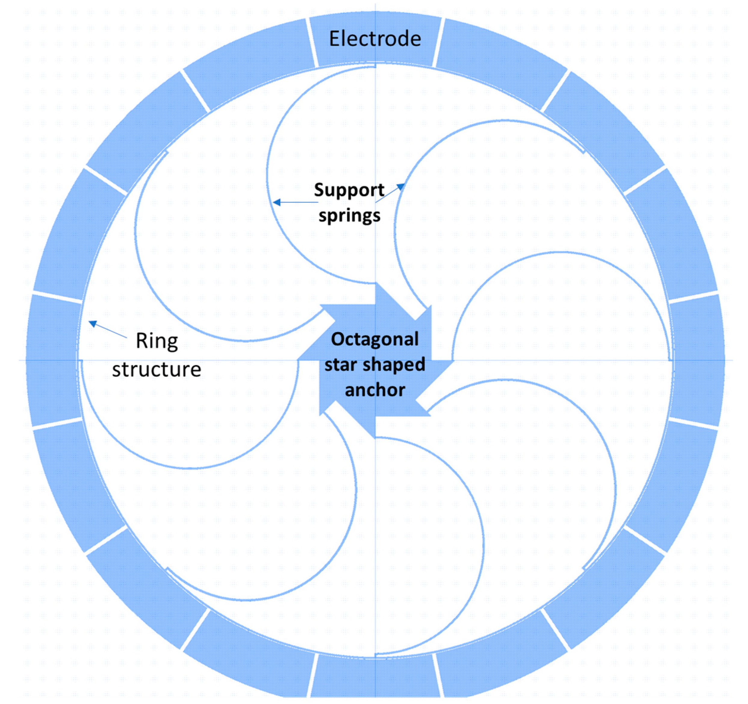
| 2018 | Khalifa University of Science and Technology, UAE [104] | Octagonal star-shaped anchor design modification approach | 1.184 kHz | 6 Hz | A (100) silicon material with 177 quality factor |
| 2019 | University of Freiburg, Germany [119] | Digital mode matching circuit on noise observations | 400 Hz | 7.6 Hz | Increased overall sensitivity and reduced bias instability |
| 2020 | Southeast University, China [120] | Automatic mode matching control loop with virtual Coriolis force | 6.27 Hz | <0.1 Hz | Sensitivity increased from 0.226 mV/deg/s to 4.13 mV/deg/s and bias instability reduced to 2.83 deg/h from 3.76 deg/h |
| 2021 | Georgia Institute of Technology, USA [121] | Laser ablation algorithm method to minimize mode mismatch | 191 Hz | 12 Hz | Scale factor measured 4.12 nA/deg/s |
Publisher’s Note: MDPI stays neutral with regard to jurisdictional claims in published maps and institutional affiliations. |
© 2022 by the authors. Licensee MDPI, Basel, Switzerland. This article is an open access article distributed under the terms and conditions of the Creative Commons Attribution (CC BY) license (https://creativecommons.org/licenses/by/4.0/).
Share and Cite
Gill, W.A.; Howard, I.; Mazhar, I.; McKee, K. A Review of MEMS Vibrating Gyroscopes and Their Reliability Issues in Harsh Environments. Sensors 2022, 22, 7405. https://doi.org/10.3390/s22197405
Gill WA, Howard I, Mazhar I, McKee K. A Review of MEMS Vibrating Gyroscopes and Their Reliability Issues in Harsh Environments. Sensors. 2022; 22(19):7405. https://doi.org/10.3390/s22197405
Chicago/Turabian StyleGill, Waqas Amin, Ian Howard, Ilyas Mazhar, and Kristoffer McKee. 2022. "A Review of MEMS Vibrating Gyroscopes and Their Reliability Issues in Harsh Environments" Sensors 22, no. 19: 7405. https://doi.org/10.3390/s22197405