
A Review on Rail Defect Detection Systems Based on Wireless Sensors

 , ,
, ,
Abstract
:1. Introduction
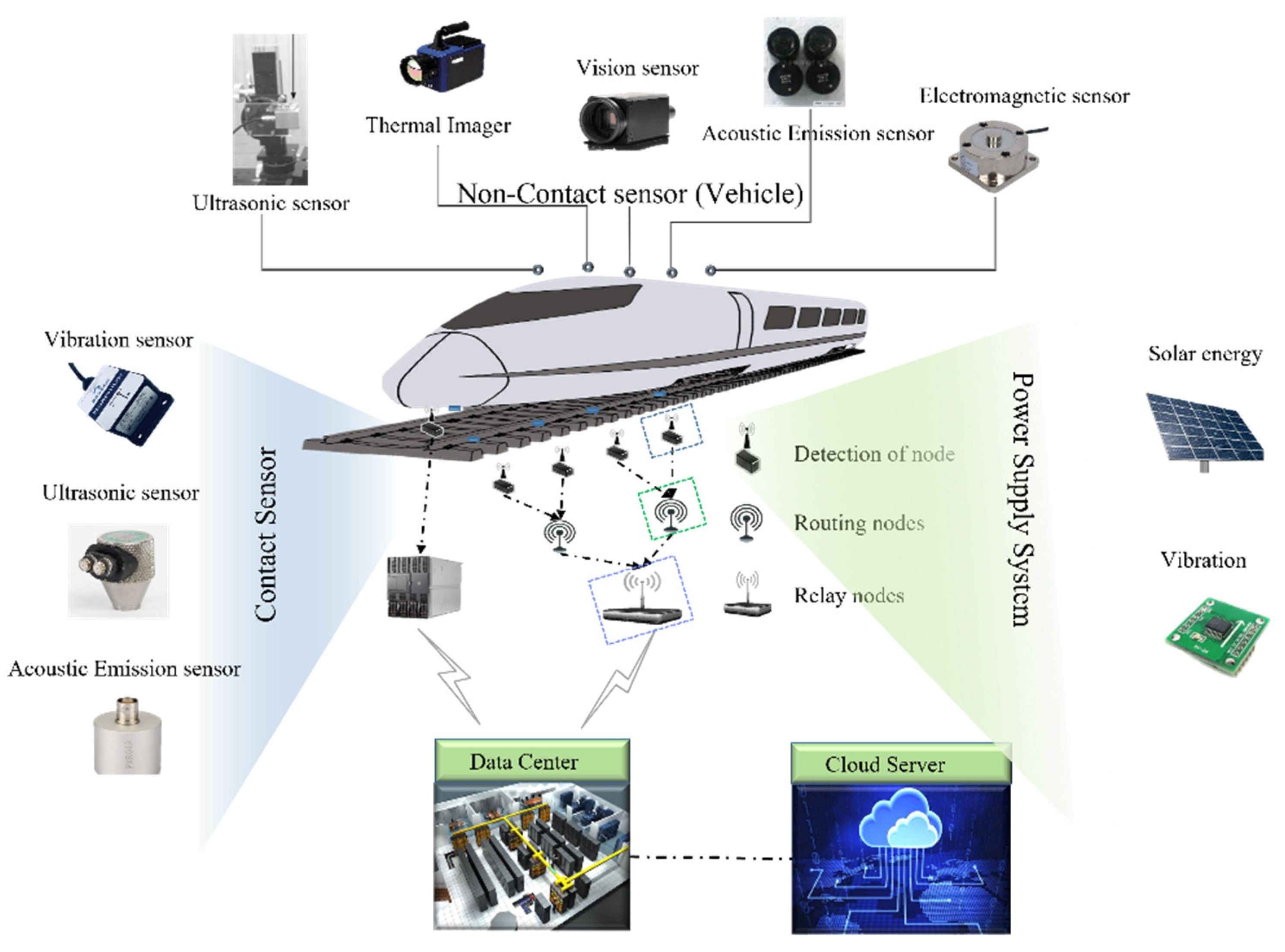
2. Sensing Method
2.1. Vibration
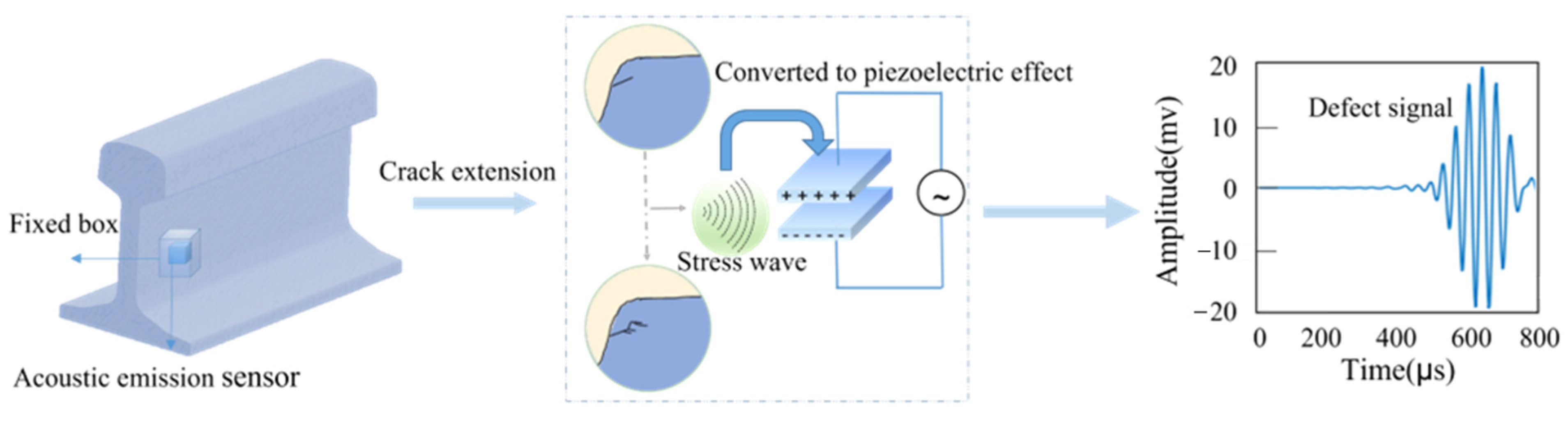
2.2. Acoustic Emission
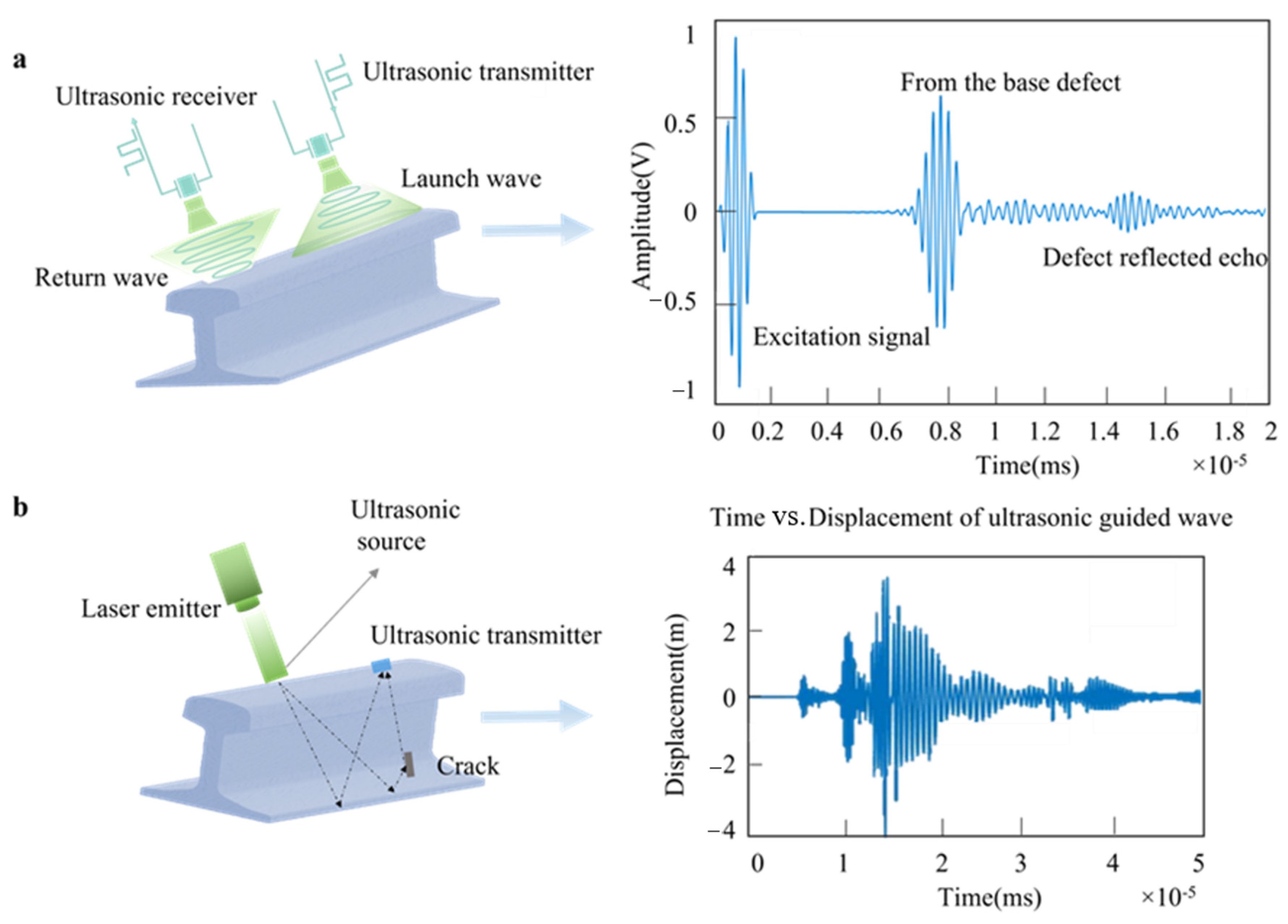
2.3. Ultrasonic
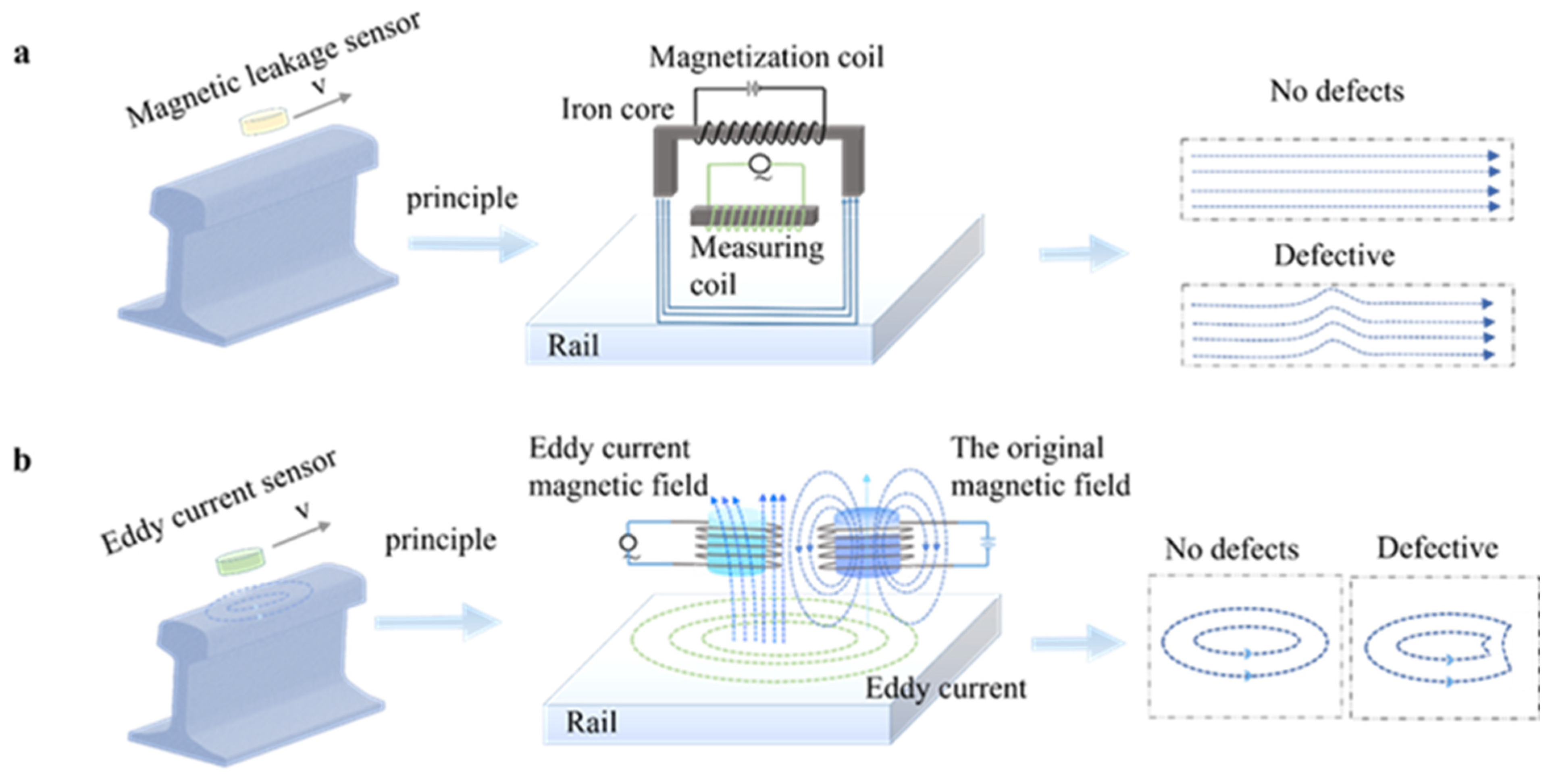
2.4. Electromagnetic
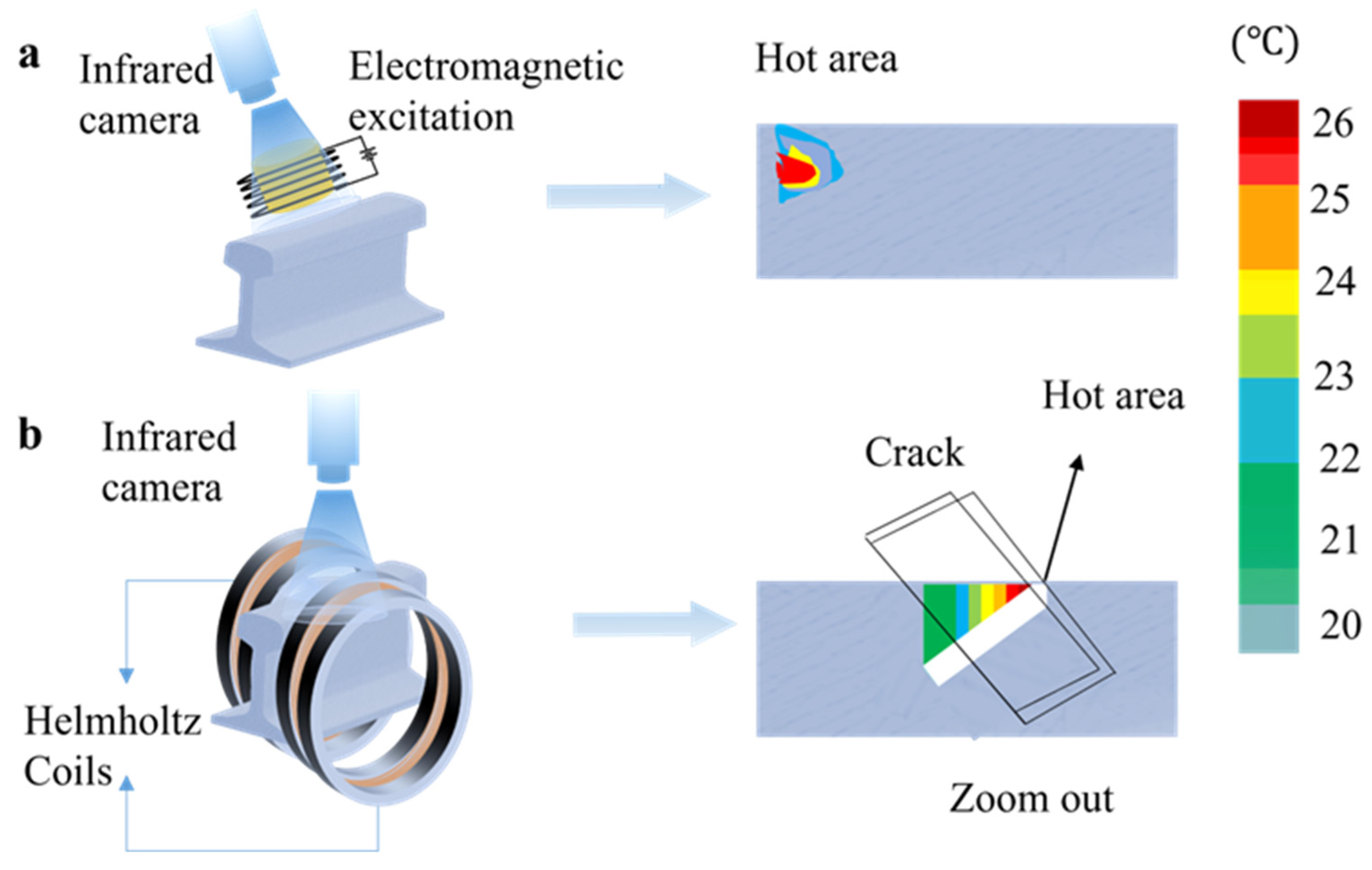
2.5. Thermal Imaging
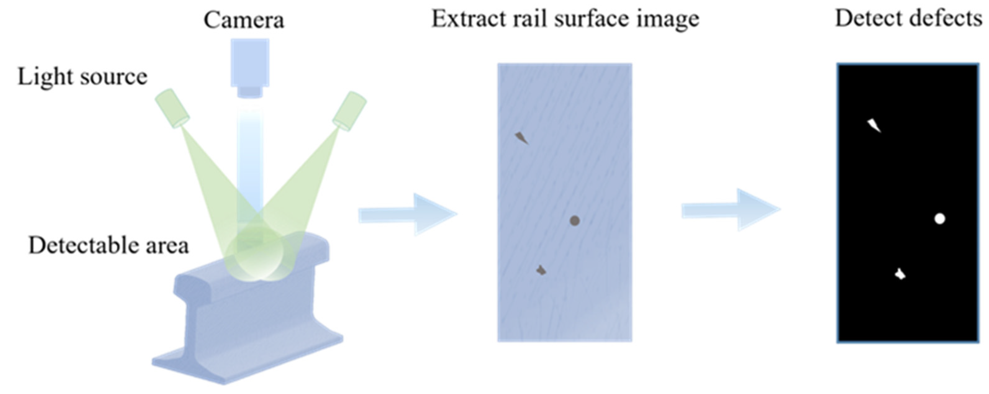
2.6. Visual
2.7. Other Detection Methods
2.8. Technology Comparison
3. Wireless Transmission
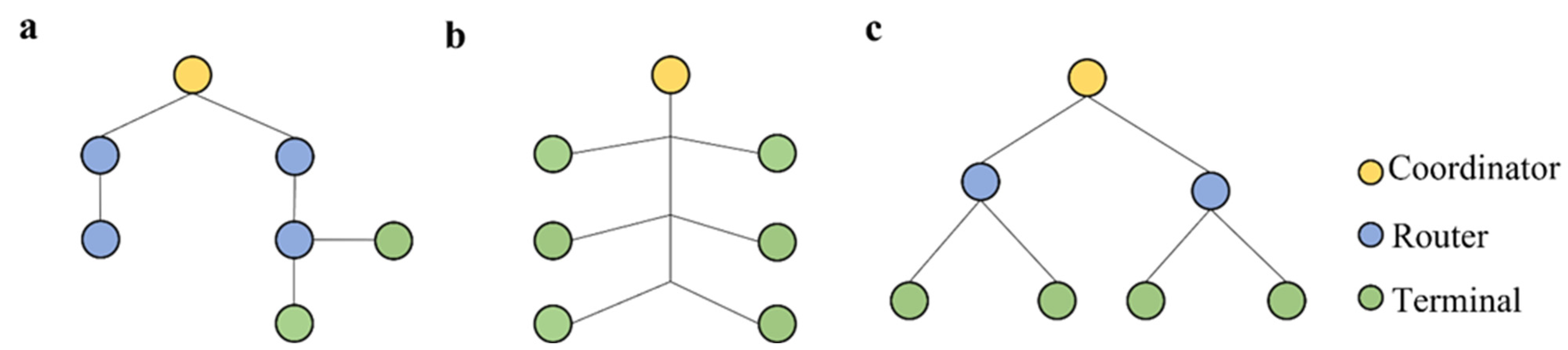
3.1. Transmission Node Settings
3.2. Transmission Media
3.3. Information Transmission
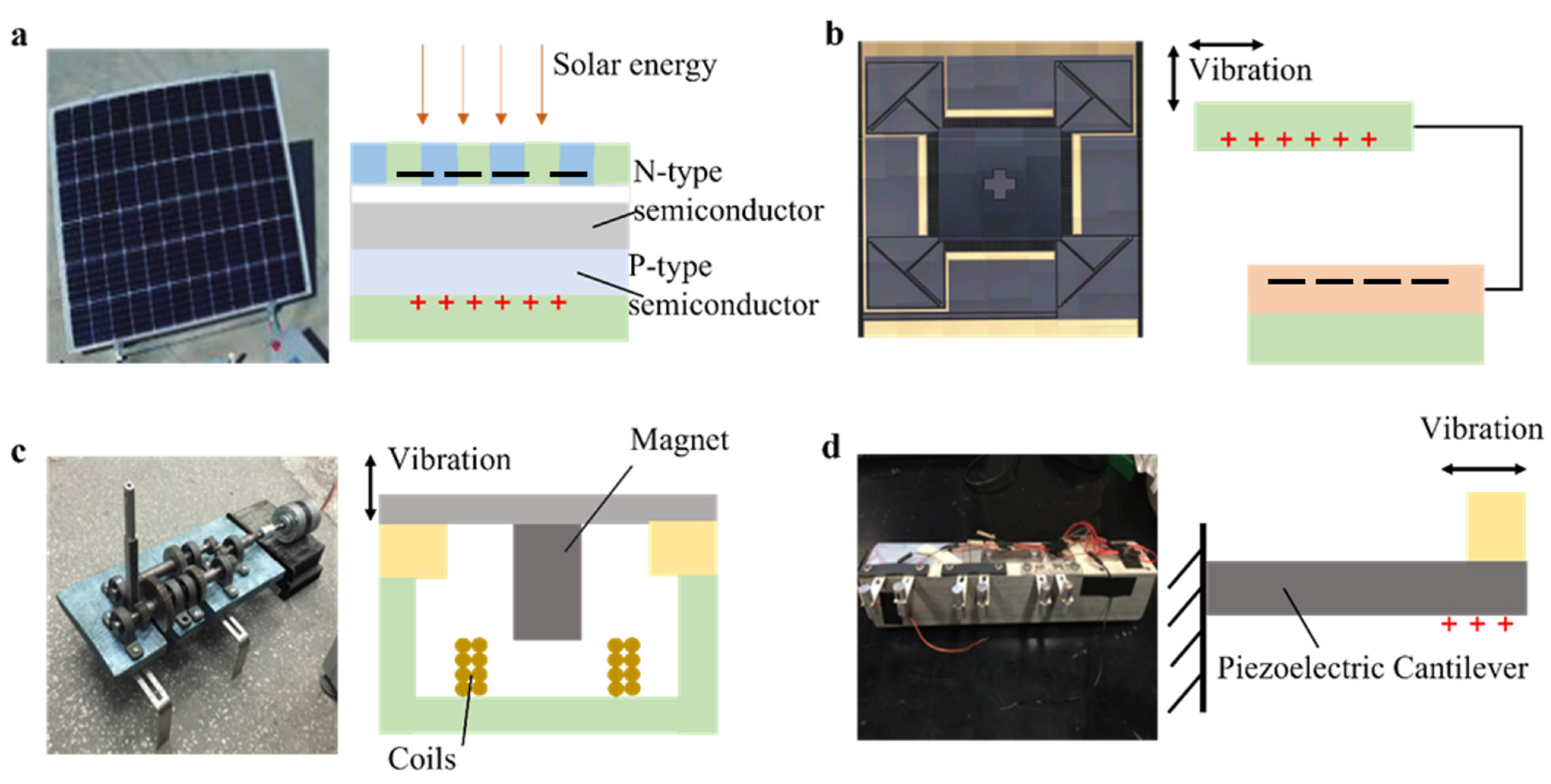
4. Power Supply
4.1. Solar
4.2. Vibration
5. Summary and Future Work
- (1)
- Rail defect feature signals can be extracted to build a complete database of rail defect and fastener defect features. This database can be used to automatically classify rail defects and determine the degree of damage to other track components.
- (2)
- For a single detection technology, it is difficult to detect all the information from the rails. Combining a variety of sensors can achieve all-round and high-precision detection of rail defects.
- (3)
- Building a comprehensive monitoring system for rail defects based on big data management and information mining technology is a good direction for achieving all-round and high-precision detection of rail infrastructure.
Author Contributions
Funding
Institutional Review Board Statement
Informed Consent Statement
Data Availability Statement
Conflicts of Interest
References
- Ishida, M.; Akama, M.; Kashiwaya, K.; Kapoor, A. The Current Status of Theory and Practice on Rail Integrity in Japanese Railways-Rolling Contact Fatigue and Corrugations. Fatigue Fract. Eng. Mater. Struct. 2003, 26, 909–919. [Google Scholar] [CrossRef]
- Islam, M.F.; Maheshwari, S.; Kumar, Y. Energy Efficient Railway Track Security Using Vibration Sensing Network. In Proceedings of the 2nd International Conference on Signal Processing and Integrated Networks, SPIN 2015, Noida, India, 19–20 February 2015; pp. 973–978. [Google Scholar] [CrossRef]
- Wang, P. Longitudinal Force Measurement in Continuous Welded Rail with Bi-Directional FBG Strain Sensors. Smart Mater. Struct. 2015, 25, 15019. [Google Scholar] [CrossRef]
- Sharma, K.; Maheshwari, S.; Solanki, R.; Khanna, V. Railway Track Breakage Detection Method Using Vibration Estimating Sensor Network: A Novel Approach. In Proceedings of the 2014 International Conference on Advances in Computing, Communications and Informatics, ICACCI 2014, Delhi, India, 24–27 September 2014; pp. 2355–2362. [Google Scholar] [CrossRef]
- Zhan, Z.; Sun, H.; Yu, X.; Yu, J.; Zhao, Y.; Sha, X.; Chen, Y.; Huang, Q.; Li, W.J. Wireless Rail Fastener Looseness Detection Based on MEMS Accelerometer and Vibration Entropy. IEEE Sens. J. 2020, 20, 3226–3234. [Google Scholar] [CrossRef]
- Kaewunruen, S.; Osman, M.H.B.; Rungskunroch, P. The Total Track Inspection. Front. Built Environ. 2019, 4, 84. [Google Scholar] [CrossRef]
- Zhang, X.; Feng, N.; Wang, Y.; Shen, Y. An Analysis of the Simulated Acoustic Emission Sources with Different Propagation Distances, Types and Depths for Rail Defect Detection. Appl. Acoust. 2014, 86, 80–88. [Google Scholar] [CrossRef]
- Yi, J. Four Times in 10 Days, Why Do Indian Trains Always Derail. Urban Mass Transit 2017, 20, 197–199. [Google Scholar]
- Goto, K.; Matsumoto, A.; Ishida, M.; Chen, H.; Kaewunruen, S. Editorial: UK-Japan Symposium on Highspeed Rails. Front. Built Environ. 2020, 6, 54. [Google Scholar] [CrossRef]
- Kaewunruen, S.; Ngamkhanong, C.; Sengsri, P.; Ishida, M. On Hogging Bending Test Specifications of Railway Composite Sleepers and Bearers. Front. Built Environ. 2020, 6, 592014. [Google Scholar] [CrossRef]
- Setsobhonkul, S.; Kaewunruen, S.; Sussman, J.M. Lifecycle Assessments of Railway Bridge Transitions Exposed to Extreme Climate Events. Front. Built Environ. 2017, 3, 35. [Google Scholar] [CrossRef] [Green Version]
- De Melo, A.L.O.; Kaewunruen, S.; Papaelias, M.; Bernucci, L.L.B.; Motta, R. Methods to Monitor and Evaluate the Deterioration of Track and Its Components in a Railway In-Service: A Systemic Review. Front. Built Environ. 2020, 6, 118. [Google Scholar] [CrossRef]
- Feng, H.; Jiang, Z.; Xie, F.; Yang, P.; Shi, J.; Chen, L. Automatic Fastener Classification and Defect Detection in Vision-Based Railway Inspection Systems. IEEE Trans. Instrum. Meas. 2014, 63, 877–888. [Google Scholar] [CrossRef]
- Deutschl, E.; Gasser, C.; Niel, A.; Werschonig, J. Defect Detection on Rail Surfaces by a Vision Based System. In Proceedings of the IEEE Intelligent Vehicles Symposium, Parma, Italy, 14–17 June 2004; pp. 507–511. [Google Scholar] [CrossRef]
- Zhong, Y.; Ma, Y.; Li, P.; Xiong, L.; Yan, F. The Existing GTC-80 Rail Inspection Vehicle Automatic System Upgrade and Transformation. Chin. Railw. 2018, 6, 98–102. [Google Scholar]
- Wei, Q.; Zhang, X.; Wang, Y.; Feng, N.; Shen, Y. Rail Defect Detection Based on Vibration Acceleration Signals. In Proceedings of the Conference Record—IEEE Instrumentation and Measurement Technology Conference, Minneapolis, MN, USA, 6–9 May 2013; pp. 1194–1199. [Google Scholar] [CrossRef]
- Min, Y.; Xiao, B.; Dang, J.; Yue, B.; Cheng, T. Real Time Detection System for Rail Surface Defects Based on Machine Vision. Eurasip J. Image Video Processing 2018, 2018, 3. [Google Scholar] [CrossRef]
- Vohra, M.; Gabhane, S.K. Efficient Monitoring System for Railways for Crack Detection. In Proceedings of the International Conference on I-SMAC (IoT in Social, Mobile, I-SMAC 2018, Palladam, India, 30–31 August 2018, Analytics and Cloud); pp. 676–681. [CrossRef]
- Hodge, V.J.; O’Keefe, S.; Weeks, M.; Moulds, A. Wireless Sensor Networks for Condition Monitoring in the Railway Industry: A Survey. IEEE Trans. Intell. Transp. Syst. 2015, 16, 1088–1106. [Google Scholar] [CrossRef]
- Aboelela, E.; Edberg, W.; Papakonstantinou, C.; Vokkarane, V. Wireless Sensor Network Based Model for Secure Railway Operations. In Proceedings of the IEEE International Performance, Computing, and Communications Conference, Phoenix, AZ, USA, 10–12 April 2006; pp. 623–628. [Google Scholar] [CrossRef]
- Grudén, M.; Westman, A.; Platbardis, J.; Hallbjörner, P.; Rydberg, A. Reliability Experiments for Wireless Sensor Networks in Train Environment. In Proceedings of the European Microwave Week 2009: Science, Progress and Quality at Radiofrequencies, Conference Proceedings—2nd European Wireless Technology Conference, EuWIT 2009, Rome, Italy, 28–29 September 2009; pp. 37–40. [Google Scholar]
- Grover, J. Anjali Wireless Sensor Network in Railway Signalling System. In Proceedings of the 2015 5th International Conference on Communication Systems and Network Technologies, CSNT 2015, Gwalior, India, 4–6 April 2015; pp. 308–313. [Google Scholar] [CrossRef]
- Tolani, M.; Sunny; Singh, R. K.; Shubham, K.; Kumar, R. Two-Layer Optimized Railway Monitoring System Using Wi-Fi and ZigBee Interfaced Wireless Sensor Network. IEEE Sens. J. 2017, 17, 2241–2248. [Google Scholar] [CrossRef]
- Zhou, D.; Shi, T.; Lv, X.; Bai, W. A Research on Banded Topology Control of Wireless Sensor Networks along High-Speed Railways. In Proceedings of the Chinese Control Conference, Hangzhou, China, 28–30 July 2015; pp. 7736–7740. [Google Scholar] [CrossRef]
- Falamarzi, A.; Moridpour, S.; Nazem, M. A Review on Existing Sensors and Devices for Inspecting Railway Infrastructure. Jurnal Kejuruteraan 2019, 31, 1–10. [Google Scholar]
- Zhang, X.; Jia, L.; Wei, X.; Ru, N. Railway Track Condition Monitoring Based on Acceleration Measurements. In Proceedings of the 2015 27th Chinese Control and Decision Conference, CCDC 2015, Qingdao, China, 23–25 May 2015; pp. 923–928. [Google Scholar] [CrossRef]
- Zhong, Y.; Gao, X.; Luo, L.; Pan, Y.; Qiu, C. Simulation of Laser Ultrasonics for Detection of Surface-Connected Rail Defects. J. Nondestruct. Eval. 2017, 36, 70. [Google Scholar] [CrossRef]
- Suhas, B.N.; Bhagavat, S.; Vimalanand, V.; Suresh, P. Wireless Sensor Networks Based Monitoring of Railway Tracks. In Proceedings of the 2018 International CET Conference on Control, Communication, and Computing, IC4 2018, Thiruvananthapuram, India, Thiruvananthapuram, India ; pp. 187–192. [CrossRef]
- Zhang, X.; Wang, K.; Wang, Y.; Shen, Y.; Hu, H. Rail Crack Detection Using Acoustic Emission Technique by Joint Optimization Noise Clustering and Time Window Feature Detection. Appl. Acoust. 2020, 160, 107141. [Google Scholar] [CrossRef]
- Yılmaz, H.; Öztürk, Z. Investigation of Rail Defects Using an Ultrasonic Inspection Method: A Case Study of Aksaray-Airport Light Rail Transit Line in Istanbul. Urban Transp. XXI 2015, 1, 687–698. [Google Scholar] [CrossRef]
- Zhu, J.; Tiany, G.; Min, Q.; Wu, J. Comparison Study of Different Features for Pocket Length Quantification of Angular Defects Using Eddy Current Pulsed Thermography. IEEE Trans. Instrum. Meas. 2019, 68, 1373–1381. [Google Scholar] [CrossRef]
- Ren, W.Z.; Min, Y.Z.; Tao, J.; Hu, J. Research on Embedded Rail Surface DefectDetection System Based on Multi Core DSP. In Proceedings of the 2018 Chinese Automation Congress, CAC 2018, Xi’an, China, 30 November–2 December 2018; pp. 4107–4112. [Google Scholar] [CrossRef]
- Chandran, P.; Rantatalo, M.; Odelius, J.; Lind, H.; Famurewa, S.M. Train-Based Differential Eddy Current Sensor System for Rail Fastener Detection. Meas. Sci. Technol. 2019, 30, 125105. [Google Scholar] [CrossRef]
- Zhang, M.; Qi, S.; Zhang, X.; Zhao, Y.; Sha, X.; Liu, L. Multi-Modal Wireless Sensor Platform for Railway Monitoring. In Proceedings of the 9th IEEE International Conference on Cyber Technology in Automation, Control and Intelligent Systems, CYBER 2019, Suzhou, China, 29 July–2 August 2019; pp. 1658–1662. [Google Scholar] [CrossRef]
- Rizzo, P.; Cammarata, M.; Bartoli, I.; di Scalea, F.L.; Salamone, S.; Coccia, S.; Phillips, R. Ultrasonic Guided Waves-Based Monitoring of Rail Head: Laboratory and Field Tests. Adv. Civ. Eng. 2010, 2010, 291293. [Google Scholar] [CrossRef]
- Netzelmann, U.; Walle, G.; Ehlen, A.; Lugin, S.; Finckbohner, M.; Bessert, S. NDT of Railway Components Using Induction Thermography. AIP Conf. Proc. 2016, 1706, 150001. [Google Scholar] [CrossRef]
- Jiang, B. Design of Railway Vibration Detection System Based on ARM and Acceleration Sensor. Master’s Thesis, Lanzhou Jiaotong University, Lanzhou, China, 2015. [Google Scholar]
- Ng, A.K.; Martua, L.; Sun, G. Dynamic Modelling and Acceleration Signal Analysis of Rail Surface Defects for Enhanced Rail Condition Monitoring and Diagnosis. In Proceedings of the 4th International Conference on Intelligent Transportation Engineering, ICITE 2019, Singapore, 5–7 September 2019; pp. 69–73. [Google Scholar] [CrossRef]
- Li, B.; Chen, X.; Wang, Z.; Tan, S. Vibration Signal Analysis for Rail Flaw Detection. In Proceedings of the 2019 11th CAA Symposium on Fault Detection, SAFEPROCESS 2019, Xiamen, China, 5–7 July 2019; pp. 830–835. [Google Scholar] [CrossRef]
- Sun, M.; Wang, Y.; Zhang, X.; Liu, Y.; Wei, Q.; Shen, Y.; Feng, N. Feature Selection and Classification Algorithm for Non-Destructive Detecting of High-Speed Rail Defects Based on Vibration Signals. In Proceedings of the Conference Record—IEEE Instrumentation and Measurement Technology Conference 2014, Montevideo, Uruguay, 12–15 May 2014; pp. 819–823. [Google Scholar] [CrossRef]
- Humbe, A.A.; Karmude, S.A. Analysis of Mechanical Vibration and Fault Detection of Railway Track Using Lab View System. Ijireeice 2019, 7, 9–15. [Google Scholar] [CrossRef]
- Milne, D.; Pen, L.L.; Watson, G.; Thompson, D.; Powrie, W.; Hayward, M.; Morley, S. Proving MEMS Technologies for Smarter Railway Infrastructure. Procedia Eng. 2016, 143, 1077–1084. [Google Scholar] [CrossRef]
- Zhao, J.; Wang, B.; Niu, W.; Li, X.; Zhang, B.; Wang, Y. Detection System of Fasteners State Based on ZigBee Networks. MATEC Web Conf. 2015, 35, 3005. [Google Scholar] [CrossRef]
- Wang, Y.; Li, X.; Zhao, J. The Design and Research of Rail Fastener State Detection System. Hardw. Circuits 2015, 39, 22–34. [Google Scholar]
- Bruzelius, K.; Mba, D. An Initial Investigation on the Potential Applicability of Acoustic Emission to Rail Track Fault Detection. NDT E Int. 2004, 37, 507–516. [Google Scholar] [CrossRef]
- Kuang, K.S.C.; Li, D.; Koh, C.G. Acoustic Emission Source Location and Noise Cancellation for Crack Detection in Rail Head. Smart Struct. Syst. 2016, 18, 1063–1085. [Google Scholar] [CrossRef]
- Jian, H.; Lee, H.R.; Ahn, J.H. Detection of Bearing/Rail Defects for Linear Motion Stage Using Acoustic Emission. Int. J. Precis. Eng. Manuf. 2013, 14, 2043–2046. [Google Scholar] [CrossRef]
- Kostryzhev, A.G.; Davis, C.L.; Roberts, C. Detection of Crack Growth in Rail Steel Using Acoustic Emission. Ironmak. Steelmak. 2013, 40, 98–102. [Google Scholar] [CrossRef]
- Hao, Q.; Zhang, X.; Wang, K.; Shen, Y.; Wang, Y. A Signal-Adapted Wavelet Design Method for Acoustic Emission Signals of Rail Cracks. Appl. Acoust. 2018, 139, 251–258. [Google Scholar] [CrossRef]
- Li, Q.; Zhong, Z.; Liang, Z.; Liang, Y. Rail Inspection Meets Big Data: Methods and Trends. In Proceedings of the 2015 18th International Conference on Network-Based Information Systems, NBiS 2015, Taipei, Taiwan, 2–4 September 2015; pp. 302–308. [Google Scholar] [CrossRef]
- Zhang, Y.; Gao, X.; Peng, C.; Wang, Z.; Li, X. Rail Inspection Research Based on High Speed Phased Array Ultrasonic Technology. Proceedings of 2016 IEEE Far East NDT New Technology and Application Forum, FENDT 2016, Nanchang, China, 22–24 June 2016; pp. 181–184. [Google Scholar] [CrossRef]
- Ling, C.; Chen, L.; Guo, J.; Gao, X.; Wang, Z.; Li, J. Research on Rail Defect Detection System Based on FPGA. In Proceedings of the 2016 IEEE Far East NDT New Technology and Application Forum, FENDT 2016, Nanchang, China, 22–24 June 2016; pp. 195–200. [Google Scholar] [CrossRef]
- Rose, J.L.; Avioli, M.J.; Mudge, P.; Sanderson, R. Guided Wave Inspection Potential of Defects in Rail. NDT E Int. 2004, 37, 153–161. [Google Scholar] [CrossRef]
- Xu, X.; Zhuang, L.; Xing, B.; Yu, Z.; Zhu, L. An Ultrasonic Guided Wave Mode Excitation Method in Rails. IEEE Access 2018, 6, 60414–60428. [Google Scholar] [CrossRef]
- Shi, H.; Zhuang, L.; Xu, X.; Yu, Z.; Zhu, L. An Ultrasonic Guided Wave Mode Selection and Excitation Method in Rail Defect Detection. Appl. Sci. 2019, 9, 1170. [Google Scholar] [CrossRef]
- Kaewunruen, S.; Ishida, M. In Situ Monitoring of Rail Squats in Three Dimensions Using Ultrasonic Technique. Exp. Tech. 2015, 40, 1179–1185. [Google Scholar] [CrossRef]
- Wang, S.J.; Chen, X.Y.; Jiang, T.; Kang, L. Electromagnetic Ultrasonic Guided Waves Inspection of Rail Base. In Proceedings of the FENDT 2014—Proceedings, 2014 IEEE Far East Forum on Nondestructive Evaluation/Testing: New Technology and Application, Increasingly Perfect NDT/E, Chengdu, China, 20–23 June 2014; pp. 135–139. [Google Scholar] [CrossRef]
- Pathak, M.; Alahakoon, S.; Spiryagin, M.; Cole, C. Rail Foot Flaw Detection Based on a Laser Induced Ultrasonic Guided Wave Method. Meas. J. Int. Meas. Confed. 2019, 148, 106922. [Google Scholar] [CrossRef]
- Li, Y.; Yao, F.; Jiao, S.; Huang, W.; Zhang, Q. Identification and Classification of Rail Damage Based on Ultrasonic Echo Signals. In Proceedings of the Chinese Control Conference, CCC 2020, Shenyang, China, 27–29 July 2020; pp. 3077–3082. [Google Scholar] [CrossRef]
- Luo, X.; Hu, Y.Q.; Liu, Y.; Huang, M.; Chu, W.; Lin, J. A Novel Text-Style Sequential Modeling Method for Ultrasonic Rail Flaw Detection. In Proceedings of the 2020 IEEE Vehicle Power and Propulsion Conference, VPPC 2020—Proceedings 2020, Gijon, Spain, 18 November–16 December 2020; pp. 1–4. [Google Scholar] [CrossRef]
- Su, X.; Zhang, X. High—Speed Railway Monitoring System Based on Wireless Sensor Network. J. Terahertz Sci. Electron. Inf. Technol. 2019, 17, 239–242. [Google Scholar]
- Wei, X.; Yang, Y.; Yu, N. Research on Broken Rail Real-Time Detection System for Ultrasonic Guided Wave. In Proceedings of the 2017 19th International Conference on Electromagnetics in Advanced Applications, ICEAA 2017, Verona, Italy, 11–15 September 2017; pp. 906–909. [Google Scholar] [CrossRef]
- Benzeroual, H.; Khamlichi, A.; Zakriti, A. Reliability of Rail Transverse Flaw Detection by Means of an Embedded Ultrasonic Based Device. MATEC Web Conf. 2018, 191, 5. [Google Scholar] [CrossRef]
- Yuan, F.; Yu, Y.; Liu, B.; Li, L. Investigation on Optimal Detection Position of DC Electromagnetic NDT in Crack Characterization for High-Speed Rail Track. In Proceedings of the I2MTC 2019—2019 IEEE International Instrumentation and Measurement Technology Conference, Proceedings 2019, Auckland, New Zealand, 20–23 May 2019. [Google Scholar] [CrossRef]
- Wang, P.; Gao, Y.; Tian, G.; Wang, H. Velocity Effect Analysis of Dynamic Magnetization in High Speed Magnetic Flux Leakage Inspection. NDT E Int. 2014, 64, 7–12. [Google Scholar] [CrossRef]
- Rajamäki, J.; Vippola, M.; Nurmikolu, A.; Viitala, T. Limitations of Eddy Current Inspection in Railway Rail Evaluation. Proc. Inst. Mech. Eng. Part F J. Rail Rapid Transit 2018, 232, 121–129. [Google Scholar] [CrossRef]
- Gao, J.; Du, G.; Wei, H. The Research of Defect Detection Test System Based on Magnetic Flux Leakage. In Proceedings of the 6th International Forum on Strategic Technology, IFOST 2011, Harbin, China, 22–24 August 2011; pp. 1225–1229. [Google Scholar] [CrossRef]
- Chen, Z.; Xuan, J.; Wang, P.; Wang, H.; Tian, G. Simulation on High Speed Rail Magnetic Flux Leakage Inspection. In Proceedings of the Conference Record—IEEE Instrumentation and Measurement Technology Conference 2011, Hangzhou, China, 10–12 May 2011; pp. 760–764. [Google Scholar] [CrossRef]
- Wang, P.; Xiong, L.; Sun, Y.; Wang, H.; Tian, G. Features Extraction of Sensor Array Based PMFL Technology for Detection of Rail Cracks. Meas. J. Int. Meas. Confed. 2014, 47, 613–626. [Google Scholar] [CrossRef]
- Ji, K.; Wang, P.; Jia, Y.; Ye, Y.; Ding, S. Adaptive Filtering Method of MFL Signal on Rail Top Surface Defect Detection. IEEE Access 2021, 9, 87351–87359. [Google Scholar] [CrossRef]
- Yang, L.; Geng, H.; Gao, S. Study on High-Speed Magnetic Flux Leakage Testing Technology Based on Multistage Magnetization. Yi Qi Yi Biao Xue Bao/Chin. J. Sci. Instrum. 2018, 39, 148–156. [Google Scholar] [CrossRef]
- Yuan, F.; Yu, Y.; Liu, B.; Tian, G. Investigation on Velocity Effect in Pulsed Eddy Current Technique for Detection Cracks in Ferromagnetic Material. IEEE Trans. Magn. 2020, 56, 6201008. [Google Scholar] [CrossRef]
- Liu, Z.; Koffman, A.D.; Waltrip, B.C.; Wang, Y. Eddy Current Rail Inspection Using AC Bridge Techniques. J. Res. Natl. Inst. Stand. Technol. 2013, 118, 140–149. [Google Scholar] [CrossRef]
- Piao, G.; Li, J.; Udpa, L.; Udpa, S.; Deng, Y. The Effect of Motion-Induced Eddy Currents on Three-Axis MFL Signals for High-Speed Rail Inspection. IEEE Trans. Magn. 2021, 57, 6200211. [Google Scholar] [CrossRef]
- Wu, Y.; Gao, B.; Zhao, J.; Liu, Z.; Luo, Q.; Shi, Y.; Xiong, L.; Tian, G.Y. Induction Thermography for Rail Nondestructive Testing under Speed Effect. In Proceedings of the 2018 IEEE Far East NDT New Technology and Application Forum, FENDT 2018, Xiamen, China, 6–8 July 2018; pp. 185–189. [Google Scholar] [CrossRef]
- Peng, J.; Tian, G.Y.; Wang, L.; Zhang, Y.; Li, K.; Gao, X. Investigation into Eddy Current Pulsed Thermography for Rolling Contact Fatigue Detection and Characterization. NDT E Int. 2015, 74, 72–80. [Google Scholar] [CrossRef]
- Gao, Y. Research on Nondestructive Detection of Rail Cracks in Multiphysical Electromagnetic and Thermal Imaging. Ph.D. Thesis, Nanjing University of Aeronautics and Astronautics, Nanjing, China, 2018. [Google Scholar]
- Gibert, X.; Patel, V.M.; Chellappa, R. Robust Fastener Detection for Autonomous Visual Railway Track Inspection. In Proceedings of the 2015 IEEE Winter Conference on Applications of Computer Vision, WACV 2015, Waikoloa, HI, USA, 5–9 January 2015; pp. 694–701. [Google Scholar] [CrossRef]
- Gao, B.; Bai, L.; Woo, W.L.; Tian, G.Y.; Cheng, Y. Automatic Defect Identification of Eddy Current Pulsed Thermography Using Single Channel Blind Source Separation. IEEE Trans. Instrum. Meas. 2014, 63, 913–922. [Google Scholar] [CrossRef]
- Usamentiaga, R.; Sfarra, S.; Fleuret, J.; Yousefi, B.; Garcia, D. Rail Inspection Using Active Thermography to Detect Rolled-in Material. In Proceedings of the 14th Quantitative InfraRed Thermography Conference, Berlin, Germany, 25–29 June 2018; pp. 845–852. [Google Scholar] [CrossRef]
- Gao, Y.; Tian, G.Y.; Wang, P.; Wang, H. Emissivity Correction of Eddy Current Pulsed Thermography for Rail Inspection. In Proceedings of the 2016 IEEE Far East NDT New Technology and Application Forum, FENDT 2016, Nanchang, China, 22–24 June 2016; pp. 108–112. [Google Scholar] [CrossRef]
- Lu, X.; Tian, G.; Wu, J.; Gao, B.; Tian, P. Pulsed Air-Flow Thermography for Natural Crack Detection and Evaluation. IEEE Sens. J. 2020, 20, 8091–8097. [Google Scholar] [CrossRef]
- Zhang, X.; Gao, B.; Shi, Y.; Woo, W.L.; Li, H. Memory Linked Anomaly Metric Learning of Thermography Rail Defects Detection System. IEEE Sens. J. 2021, 21, 24720–24730. [Google Scholar] [CrossRef]
- Ramzan, B.; Malik, S.; Ahmad, S.M.; Martarelli, M. Railroads Surface Crack Detection Using Active Thermography. In Proceedings of the 18th International Bhurban Conference on Applied Sciences and Technologies, IBCAST 2021, Islamabad, Pakistan, 12–16 January 2021; pp. 183–197. [Google Scholar] [CrossRef]
- Guo, L.; Zhang, J.; Chen, Z.; Sun, L.; Ge, J.; Lü, K.; Dai, G. Automatic Detection for Defects of Railroad Track Surface. Appl. Mech. Mater. 2013, 278–280, 856–860. [Google Scholar] [CrossRef]
- Fu, S.; Jiang, Z. Research on Image-Based Detection and Recognition Technologies for Cracks on Rail Surface. In Proceedings of the 2019 International Conference on Robots and Intelligent System, ICRIS 2019, Haikou, China, 15–16 June 2019; pp. 98–101. [Google Scholar] [CrossRef]
- Yaman, O.; Karakose, M.; Akin, E. A Vision Based Diagnosis Approach for Multi Rail Surface Faults Using Fuzzy Classificiation in Railways. In Proceedings of the 2nd International Conference on Computer Science and Engineering, UBMK 2017, Antalya, Turkey, 5–8 October 2017; pp. 713–718. [Google Scholar] [CrossRef]
- Gan, J.; Li, Q.; Wang, J.; Yu, H. A Hierarchical Extractor-Based Visual Rail Surface Inspection System. IEEE Sens. J. 2017, 17, 7935–7944. [Google Scholar] [CrossRef]
- Liang, Z.; Zhang, H.; Liu, L.; He, Z.; Zheng, K. Defect Detection of Rail Surface with Deep Convolutional Neural Networks. In Proceedings of the World Congress on Intelligent Control and Automation (WCICA), Changsha, China, 4–8 July 2018; pp. 1317–1322. [Google Scholar] [CrossRef]
- Lu, J.; Liang, B.; Lei, Q.; Li, X.; Liu, J.; Liu, J.; Xu, J.; Wang, W. SCueU-Net: Efficient Damage Detection Method for Railway Rail. IEEE Access 2020, 8, 125109–125120. [Google Scholar] [CrossRef]
- Zhuang, L.; Qi, H.; Zhang, Z. The Automatic Rail Surface Multi-Flaw Identification Based on a Deep Learning Powered Framework. IEEE Trans. Intell. Transp. Syst. 2021, 23, 12133–12143. [Google Scholar] [CrossRef]
- Yu, H.; Li, Q.; Tan, Y.; Gan, J.; Wang, J.; Geng, Y.A.; Jia, L. A Coarse-to-Fine Model for Rail Surface Defect Detection. IEEE Trans. Instrum. Meas. 2019, 68, 656–666. [Google Scholar] [CrossRef]
- Yuan, H.; Chen, H.; Liu, S.; Lin, J.; Luo, X. A Deep Convolutional Neural Network for Detection of Rail Surface Defect. In Proceedings of the 2019 IEEE Vehicle Power and Propulsion Conference, VPPC 2019—Proceedings 2019, Hanoi, Vietnam, 14–17 October 2019; pp. 2019–2022. [Google Scholar] [CrossRef]
- Mao, Q.; Cui, H.; Hu, Q.; Ren, X. A Rigorous Fastener Inspection Approach for High-Speed Railway from Structured Light Sensors. ISPRS J. Photogramm. Remote Sens. 2018, 143, 249–267. [Google Scholar] [CrossRef]
- Divya, V. Crack Detection for Railway Tracks and Accident Prevention. Int. J. Res. Appl. Sci. Eng. Technol. 2017, V, 448–450. [Google Scholar] [CrossRef]
- Wei, J.; Liu, C.; Ren, T.; Liu, H.; Zhou, W. Online Condition Monitoring of a Rail Fastening System on High-Speed Railways Based on Wavelet Packet Analysis. Sensors 2017, 17, 318. [Google Scholar] [CrossRef]
- Tian, G.Y.; Gao, B. Review of Railway Rail Defect Non-Destructive Testing and Monitoring. J. Instrum. 2016, 37, 1763–1780. [Google Scholar] [CrossRef]
- Jiang, Y.; Wang, H.; Tian, G.; Chen, S.; Zhao, J.; Liu, Q.; Hu, P. Non-Contact Ultrasonic Detection of Rail Surface Defects in Different Depths. Proceedings of 2018 IEEE Far East NDT New Technology and Application Forum, FENDT 2018, Xiamen, China, 6–8 July 2018; pp. 46–49. [Google Scholar] [CrossRef]
- Song, Z.; Yamada, T.; Shitara, H.; Takemura, Y. Detection of Damage and Crack in Railhead by Using Eddy Current Testing. J. Electromagn. Anal. Appl. 2011, 3, 546–550. [Google Scholar] [CrossRef]
- Wei, X.; Yang, Z.; Liu, Y.; Wei, D.; Jia, L.; Li, Y. Railway Track Fastener Defect Detection Based on Image Processing and Deep Learning Techniques: A Comparative Study. Eng. Appl. Artif. Intell. 2019, 80, 66–81. [Google Scholar] [CrossRef]
- Chen, R.; Shi, T.; Lv, X. Transmission Performance Analysis of Wireless Sensor Networks under Complex Railway Environment. In Proceedings of the 29th Chinese Control and Decision Conference, CCDC 2017, Chongqing, China, 28–30 May 2017; pp. 2970–2974. [Google Scholar] [CrossRef]
- Duan, J.; Shi, T.; Lv, X.; Li, Z. Optimal Node Deployment Scheme for WSN-Based Railway Environment Monitoring System. In Proceedings of the 28th Chinese Control and Decision Conference, CCDC 2016, Yinchuan, China, 28–30 May 2016; pp. 6529–6534. [Google Scholar] [CrossRef]
- Lv, X.; Li, J.; Shi, T.; Jia, X. Topology Analysis Based on Linear Wireless Sensor Networks in Monitoring of High-Speed Railways. In Proceedings of the 28th Chinese Control and Decision Conference, CCDC 2016, Yinchuan, China, 28–30 May 2016; pp. 1797–1802. [Google Scholar] [CrossRef]
- Germaine, J.T.; Whittle, A.J. Low Cost Monitoring System to Diagnose Problematic Rail Bed: Case Study at a Mud Pumping Site. Ph.D. Thesis, Massachusetts Institute of Technology, Cambridge, MA, USA, 2007; p. 203. [Google Scholar]
- Hernandez, A.; Valdovinos, A.; Perez-Diaz-De-Cerio, D.; Valenzuela, J.L. Bluetooth Low Energy Sensor Networks for Railway Applications. In Proceedings of the IEEE Sensors, Glasgow, UK, 29 October–1 November 2017; pp. 1–3. [Google Scholar] [CrossRef]
- Gao, M.; Wang, P.; Wang, Y.; Yao, L. Self-Powered ZigBee Wireless Sensor Nodes for Railway Condition Monitoring. IEEE Trans. Intell. Transp. Syst. 2018, 19, 900–909. [Google Scholar] [CrossRef]
- Nallathambi, M.M. Remote Sensor Networks for Condition Monitoring: An Application on Railway Industry. In Proceedings of the 2017 IEEE International Conference on Electrical, Instrumentation and Communication Engineering (ICEICE), Karur, India, 27–28 April 2017. [Google Scholar] [CrossRef]
- Kljaic, Z.; Cipek, M.; Mlinaric, T.J.; Pavkovic, D.; Zorc, D. Utilization of Track Condition Information from Remote Wireless Sensor Network in Railways-A Mountainous Rail Track Case Study. In Proceedings of the 27th Telecommunications Forum, TELFOR 2019, Belgrade, Serbia, 26–27 November 2019. [Google Scholar] [CrossRef]
- Punetha, D.; Tripathi, D.M.; Kumar, A. A Wireless Approach with Sensor Network for Real Time Railway Track Surveillance System. Int. J. Eng. Trends Technol. 2014, 9, 426–429. [Google Scholar] [CrossRef]
- Philipose, A.; Rajesh, A. Investigation on Energy Efficient Sensor Node Placement in Railway Systems. Eng. Sci. Technol. Int. J. 2016, 19, 754–768. [Google Scholar] [CrossRef]
- Munadi, R.; Sulistyorini, A.E.; Fauzi, F.U.S.; Adiprabowo, T. Simulation and Analysis of Energy Consumption for S-MAC and T-MAC Protocols on Wireless Sensor Network. In Proceedings of the APWiMob 2015—IEEE Asia Pacific Conference on Wireless and Mobile, Bandung, Indonesia, 27–29 August 2015; pp. 142–146. [Google Scholar] [CrossRef]
- Shafiullah, G.M.; Azad, S.A.; Ali, A.B.M.S. Energy-Efficient Wireless Mac Protocols for Railway Monitoring Applications. IEEE Trans. Intell. Transp. Syst. 2013, 14, 649–659. [Google Scholar] [CrossRef]
- Philipose, A.; Rajesh, A. Performance Analysis of an Improved Energy Aware MAC Protocol for Railway Systems. In Proceedings of the 2nd International Conference on Electronics and Communication Systems, ICECS 2015, Coimbatore, India, 26–27 February 2015; pp. 233–236. [Google Scholar] [CrossRef]
- Zhang, H.; Jiang, H. Research and Application on WSNs of Monitoring High-Speed Rail Infrastructure Based on ZigBee. Railw. Comput. Appl. 2013, 22, 44–47. [Google Scholar]
- Chomsuwan, K.; Srisuthep, N.; Pichitronnachai, C.; Toshiyuki, U. Energy Free Railway Monitoring with Vibrating Magnetostrictive Sensor for Wireless Network Sensor. In Proceedings of the International Conference on Sensing Technology, ICST 2018, Sydney, NSW, Australia, 4–6 December 2017; pp. 1–5. [Google Scholar] [CrossRef]
- Sharma, H.; Haque, A.; Jaffery, Z.A. Solar Energy Harvesting Wireless Sensor Network Nodes: A Survey. J. Renew. Sustain. Energy 2018, 10, 023704. [Google Scholar] [CrossRef]
- Shang, Q.; Guo, H.; Liu, X.; Zhou, M. A Wireless Energy and Thermoelectric Energy Harvesting System for Low Power Passive Sensor Network. In Proceedings of the 2020 IEEE MTT-S International Wireless Symposium, IWS 2020—Proceedings 2020, Shanghai, China, 20–23 September 2020; pp. 2020–2022. [Google Scholar] [CrossRef]
- Kim, S.; Bang, S.; Chun, K. Temperature Effect on the Vibration-Based Electrostatic Energy Harvester. In Proceedings of the IEEE Region 10 Annual International Conference, Proceedings/TENCON 2011, Sanur, Bali, Indonesia, 21–24 November 2011; pp. 1317–1320. [Google Scholar] [CrossRef]
- Zhang, X.; Zhang, Z.; Pan, H.; Salman, W.; Yuan, Y.; Liu, Y. A Portable High-Efficiency Electromagnetic Energy Harvesting System Using Supercapacitors for Renewable Energy Applications in Railroads. Energy Convers. Manag. 2016, 118, 287–294. [Google Scholar] [CrossRef]
- Li, J.; Jang, S.; Tang, J. Implementation of a Piezoelectric Energy Harvester in Railway Health Monitoring. In Proceedings of the Sensors and Smart Structures Technologies for Civil, Mechanical, and Aerospace Systems 2014, San Diego, CA, USA, 9–13 March 2014; Volume 9061, p. 90612. [Google Scholar] [CrossRef]
- Alva, G.; Liu, L.; Huang, X.; Fang, G. Thermal Energy Storage Materials and Systems for Solar Energy Applications. Renew. Sustain. Energy Rev. 2017, 68, 693–706. [Google Scholar] [CrossRef]
- Kalaagi, M.; Seetharamdoo, D. Electromagnetic Energy Harvesting Systems in the Railway Environment: State of the Art and Proposal of a Novel Metamaterial Energy Harvester. In Proceedings of the 13th European Conference on Antennas and Propagation, EuCAP 2019, Krakow, Poland, 31 March–5 April 2019; pp. 7–11. [Google Scholar]
- Tianchen, Y.; Jian, Y.; Ruigang, S.; Xiaowei, L. Vibration Energy Harvesting System for Railroad Safety Based on Running Vehicles. Smart Mater. Struct. 2014, 23, 125046. [Google Scholar] [CrossRef]
- Zhao, X.; Wei, G.; Li, X.; Qin, Y.; Xu, D.; Tang, W.; Yin, H.; Wei, X.; Jia, L. Self-Powered Triboelectric Nano Vibration Accelerometer Based Wireless Sensor System for Railway State Health Monitoring. Nano Energy 2017, 34, 549–555. [Google Scholar] [CrossRef]
- Wang, J.; Shi, Z.; Xiang, H.; Song, G. Modeling on Energy Harvesting from a Railway System Using Piezoelectric Transducers. Smart Mater. Struct. 2015, 24, 105017. [Google Scholar] [CrossRef]
- Gao, M.; Wang, P.; Cao, Y.; Chen, R.; Cai, D. Design and Verification of a Rail-Borne Energy Harvester for Powering Wireless Sensor Networks in the Railway Industry. IEEE Trans. Intell. Transp. Syst. 2017, 18, 1596–1609. [Google Scholar] [CrossRef]


| Methods | Types of Detected Defects | Algorithm | Results | Comments |
|---|---|---|---|---|
| MEMS accelerometers | Rail fastener [5] | Finite element method | Reliable identification of fasteners with a looseness factor greater than 60% | Small size, low price, high accuracy |
| / [42] | The high- and low-pass filter | This study proves that MEMS sensors are suitable for rail defect detection. | ||
| Rail head sag, rail surface stripping, height joint [40]. | Peak-finding algorithm | The accuracy rate of the classification of rail defect types can reach 93.8%. | ||
| Strain gauge | Rail fastener [43] | Sequential backward selection | Demonstrated a linear relationship between strain voltage and fastener tightness. | Small size, low price, low accuracy |
| Rail fastener [44] | Support vector machines | Demonstrated a linear relationship between strain voltage and fastener tightness. |
| Methods | Types of Detected Defects | Algorithm | Results | Comments |
|---|---|---|---|---|
| AE | Rail-head defects [46] | Hilbert transform Wavelet transform | The error of the location of rail defects is less than 0.3 m. Detection distance can reach 30 m. | Long detection distance |
| AE | /[49] | Signal adapted wavelet in the frame of a two-band analysis/synthesis system | The wavelet designed by the proposed method has superior performance in expressing the defect AE signal, and can outperform the most suitable existing wavelet. | The designed wavelet shows good robustness against noise, which has profound meaning for rail defect detection in practical applications. |
| AE | Rail fatigue defect [48] | Single-hit waveform and power spectrum analysis | High duration, low frequency signals result from ductile fractures. Low duration, high frequency signals result from brittle fractures. | It is demonstrated that the AE signal associated with defect propagation depends on the fracture mode. |
| AE | Rail defect, small bearing defect, and worse bearing defect [47] | Cepstrum analysis | This study verifies that AE signals can detect bearing/rail defects. |
| Methods | Algorithm or Simulation | Types of Detectable Defects | Results | Summarize | ||
|---|---|---|---|---|---|---|
| Detection Method | Ordinary ultrasound | Multi-angle ultrasonic probe [59] | PCA and LSSVM | Different types of defects in rail head, rail waist and rail foot | Classification recognition accuracy: 92%. Identify seven types of rail defects. | Ordinary ultrasonic waves are usually single-modal at low frequencies, and cannot achieve high-sensitivity omnidirectional detection of all parts of the rail (track surface, underground, and interior). |
| Combination of wheeled ultrasonic probes [60] | LSTM-based deep learning model | Average f1-score: 95.5%. Maximum detection speed: 22 m/s. | ||||
| Phased array ultrasonic | Combination of the conventional probe and phased array probe [51] | / | Defects around bolt holes, vertical defects and transverse imperfections in the rail head, waist and foundation area | Ultrasonic beam coverage rate up to 80% | The rails can be inspected more comprehensively and the inspection efficiency is improved. Multiple angles monitoring the same area. | |
| Phased array with transverse wedge block(railhead), transverse and longitudinal wave probes (rail waist and rail foot) [61] | / | Different types of defects in rail head, rail waist and rail foot | Effectively covers the railhead, rail foot, and rail waist | |||
| Combination of the conventional probe and phased array probe [52] | / | Different types of defects in rail head, rail waist and rail foot | The detection accuracy can reach 6 mm. | |||
| Ultrasonic guided wave | High voltage pulse sequences [62] | / | / | Coverage up to 1000 m | The efficiency of ultrasonic guided wave detection of rail defects is much greater than the ultrasonic waves. | |
| Sine wave modulated by the Hanning window with a frequency of 35 kHz [55] | Phase control and time delay technology. | Rail head, rail waist and rail foot | Enhance expected mode and suppress interference mode. The optimal excitation direction and excitation node of the modes are calculated. | |||
| Excitation source | Laser ultrasonic | High energy laser pulses [58] | Finite element simulations | Rail foot | The best detection position is 300 mm in front of the defect position. The best detection frequency is 20 KHZ. | Can cover the head, web, and foot parts of the rail |
| Non-ablative laser source [63] | Analysis of Variance. Monte-Carlo simulations. | Head surface defects, horizontal defects, vertical longitudinal split defects, star defects at colt holes and diagonal defect in waist. | The position of the sensor has a greater impact on detection accuracy. The research results can find the best detection position of the sensor. | |||
| Hybrid laser/air coupling sensor system [35] | Wavelet transform and outlier analysis. | Surface defects(Transverse defects and alongitudinal defects) | Inner defects and surface defects of the rail can be distinguished. | |||
| Two staggered beams of laser [27] | Finite element simulations. | Irregular scratches on rail surface | The error is about 0.014%. | |||
| Electromagnetic ultrasonic | / | Finite element analysis [57] | Rail base | Able to detect common defects in rail bases | No couplant required | |
| Methods | Algorithm or Simulation | Types of Detectable Defects | Research Content and Results | |
|---|---|---|---|---|
| Eddy current | Pulsed eddy current [72] | 3D transient model | Different installation positions can detect rail defects in different parts. |
|
| Direct current [64] | 2D Finite element method | Different installation positions can detect rail defects in different parts. |
| |
| AC bridge techniques [73] | Digital lock-in amplifier algorithm | Four typical types of rail defects (transverse defects, compound fissure, crushed head, detail fracture) |
| |
| Differential eddy-current (EC) sensor system [33] |
| The degree of looseness of fasteners |
| |
| Magnetic flux leakage | Pulsed magnetic flux leakage [69] | 2D transient analysis model under | Vertical and oblique defects |
|
| Multistage magnetization [71] | Finite element method | Rail inner defects |
| |
| Direct current [68] | 2D simulation model | Oblique defect and rectangle defect |
| |
| Magnetic flux leakage [70] | Improved adaptive filtering | Different types of defects in rail surface |
| |
| Combination of permanent magnets and yoke [74] | 3-D FEM simulations | Different types of defects in rail surface |
| |
| Thermal Stimulation | Algorithm | Types of Detectable Defects | Results | Comments | |
|---|---|---|---|---|---|
| Eddy current | Eddy-current pulsed thermography [79] | Single-channel blind source separation | Thermal fatigue defects | The method can automatically detect rail defects in both the time and the spatial domains. |
|
| Helmholtz coils [76] | Finite element method | Rolling contact fatigue (RCF) defects | Solved the problem that the excitation of ordinary coils on the rails would cause unstable detection areas |
| |
| Various shapes of sensors [75] | Inverse Fourier transformation (deblurring method) | RCF defects and micro-defect | Verify the detection effect of various shape sensors |
| |
| Easyheat 224 system with induction heater [81] | Normalized difference vegetation index (NDVI) | RCF defects | The proposed method can have a good correction for the emissivity. |
| |
| Laser | Two halogen lamps [80] | / | Rolled-in material defect | Defects of 1 cm2 can be detected. |
|
| Pulsed air-flow thermography [82] | Subtract the first image in the sequence from the last image acquired in the heating sequence when removing the background. | Rail surface defects | The study proved that the pulsed air-flow thermography method used in the experiment is effective for detecting rail defects. |
| |
| High-frequency continuous sine-wave current [83] | Metric learning modules | Fatigue defects | The method proposed in this study can not only reduce the influence of interference factors but also expand the feature space distance between defective samples and normal samples. |
| |
| Apply uniform heat flux for a time [84] | pulse phase thermography (PPT) | Lateral surface defects | After thermal stimulation for the same time, the cooling rate of shallow defects is faster than that of deep defects. |
| |
| Algorithm | Results | Comments | Summarize | |
|---|---|---|---|---|
| Traditional algorithm | Hough transform and improved Sobel algorithm [85] | Minimum detection area: 0.0068 cm2 |
| Weak generalization ability and low accuracy |
| Otsu segmentation and fuzzy logic [87] | The success rate of identifying defect types: 72.05% |
| ||
| Coarse-to-fine model [88,92] | CTFM outperforms state-of-the-art methods in terms of pixel-level indices and defect-level indices. |
| ||
| Deep learning | SegNet [89] | Detection accuracy:100% |
| Strong generalization ability and high accuracy |
| SCueU-Net [90] | Detection accuracy:99.76% |
| ||
| MOLO [93] | This algorithm improves the accuracy 3–5% more than the YOLOv3 algorithm. |
| ||
| Cascading rail surface flaw identifier [91] | The detection accuracy rate of defect type: 98.2% |
| ||
| Detection Method | Types of Detectable Defects | Detection Performance | Influence of Environment on Detection Performance | |||
|---|---|---|---|---|---|---|
| Vibration accelerometer | Temperatures that are too low will reduce the sensitivity of the sensor. | |||||
| Ultrasonic | Ordinary ultrasonic [51,52,61] | Conventional probe |
|
| In high-speed inspection systems, rail defects with a depth of less than 4 mm are often undetectable [76]. | When the temperature changes, it will affect the speed of the sound wave in the rail, so the localization of the defect will have an impact. |
| Phased array probe |
| |||||
| Electromagnetic ultrasonic |
|
| ||||
| Laser ultrasonic |
|
| ||||
| AE |
| Other noises will affect the detection results. | ||||
| Electromagnetic | MFL | The temperature will drift the detection results of the eddy-current sensor, and the two are negatively correlated.The increase in temperature will cause the magnetic permeability to decrease. | ||||
| ECI |
| |||||
| Thermal imaging | Contamination present on the Rail surface will attenuate the signal. | |||||
| Vision |
| Contaminants such as snowflakes and leaves can block rail defects, making visual inspection methods unable to detect rail defects. | ||||
| Network Topology | Advantages | Disadvantages | References |
|---|---|---|---|
| Star topology |
|
| [43,102] |
| Tree topology |
|
| [20,24] |
| Line topology |
|
| [103] |
| Energy Harvesting Device | Application Conditions | Installation Location | Voltage | Power | Reference |
|---|---|---|---|---|---|
| Piezoelectric energy harvester | 2.5 mph (the speed of the train) The resistor connected in the PZT0 (a single piezoelectric energy harvester) was 9.9 KΩ |  | 40 V (the maximum voltage) | 0.18 mW (the maximum power) | [120] |
| Magnetic levitation oscillator | 105 km/h (the speed of the train) (one-car train) |  | 2.3 V (peak–peak output voltage) | / | [106] |
| Galfenol magnetostictive device | 60 km/h (the speed of the train) 60 m (The train is far from the sensor of 60 m.) |  | 0.15 V (The voltage varies with the distance between the train and the sensor, when the distance is shorter, the voltage is larger, and the longer the distance, the smaller the voltage.) | When the terminal voltage is about 0.56 V, the power is maximum. | [115] |
| A patch-type piezoelectric transducer | 30 m/s (the speed of the train) |  | 4.82 V (at the beginning of a valid signal) | 0.19 mW (at the beginning of a valid signal) | [125] |
| Drum transducer | 0.15 m/s (running speed) 120 kg (the weight of a fully-loaded train) |  | 50–70 V (peak open-circuit voltage) | 100 mW | [123] |
| Electromagnetic energy harvesting system | 6 mm (amplitude) 1 Hz and 2 Hz (frequencies) |  | 6.45 V (the output peak–peak voltage) | 0.0912 J | [119] |
| Magnetic levitation harvester | low-frequency (3–7 Hz) Rail displacement |  | 2.32 V (the output peak–peak voltage) | 119 mW | [126] |
Publisher’s Note: MDPI stays neutral with regard to jurisdictional claims in published maps and institutional affiliations. |
© 2022 by the authors. Licensee MDPI, Basel, Switzerland. This article is an open access article distributed under the terms and conditions of the Creative Commons Attribution (CC BY) license (https://creativecommons.org/licenses/by/4.0/).
Share and Cite
Zhao, Y.; Liu, Z.; Yi, D.; Yu, X.; Sha, X.; Li, L.; Sun, H.; Zhan, Z.; Li, W.J. A Review on Rail Defect Detection Systems Based on Wireless Sensors. Sensors 2022, 22, 6409. https://doi.org/10.3390/s22176409
Zhao Y, Liu Z, Yi D, Yu X, Sha X, Li L, Sun H, Zhan Z, Li WJ. A Review on Rail Defect Detection Systems Based on Wireless Sensors. Sensors. 2022; 22(17):6409. https://doi.org/10.3390/s22176409
Chicago/Turabian StyleZhao, Yuliang, Zhiqiang Liu, Dong Yi, Xiaodong Yu, Xiaopeng Sha, Lianjiang Li, Hui Sun, Zhikun Zhan, and Wen Jung Li. 2022. "A Review on Rail Defect Detection Systems Based on Wireless Sensors" Sensors 22, no. 17: 6409. https://doi.org/10.3390/s22176409