
Wireless Power Transfer: Systems, Circuits, Standards, and Use Cases

 , , ,
, , ,  , , and
Abstract
:1. Introduction
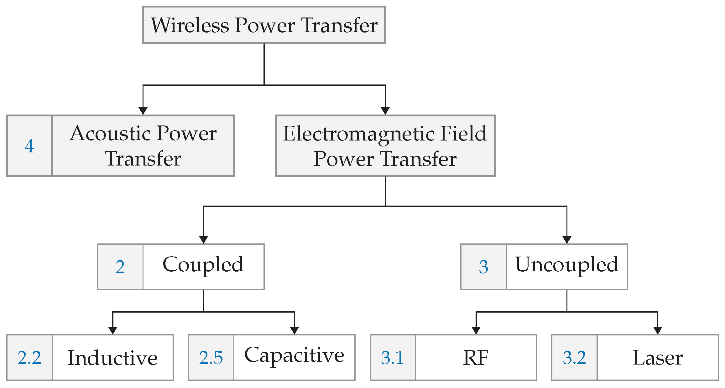
2. Electromagnetic-Coupled Technologies
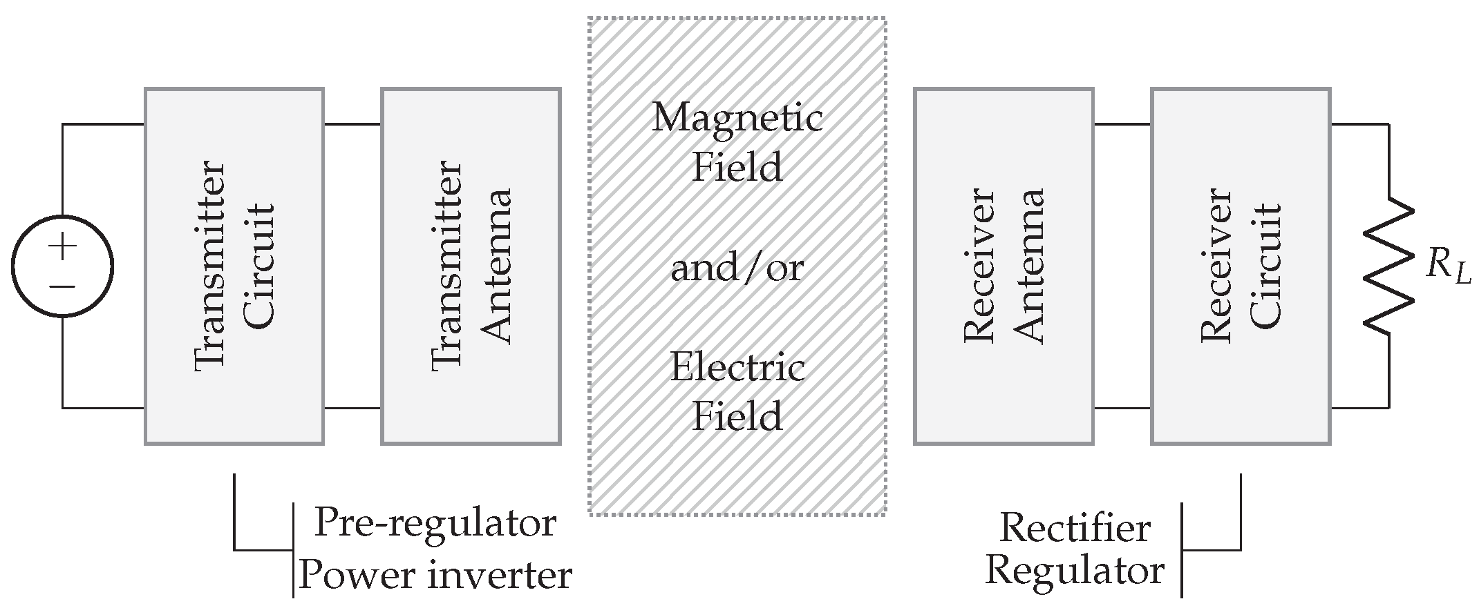
2.1. Overview of an EM-Coupled System
2.1.1. Power Supply
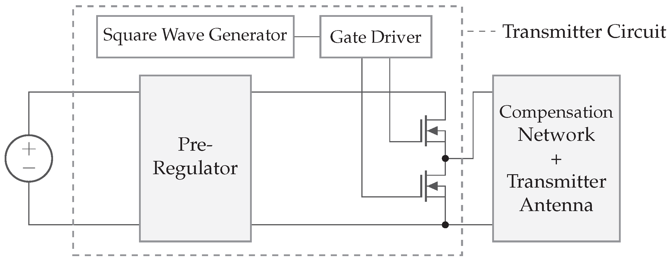
2.1.2. Transmitter Circuit
2.1.3. Compensation Network and Antenna
2.1.4. Receiver Circuit
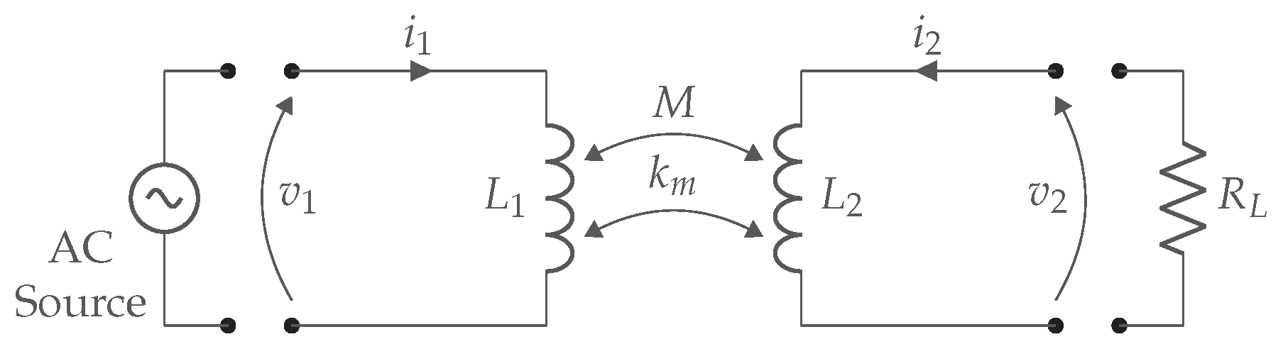
2.2. Inductive Coupling
2.3. Magnetic Resonance Coupling
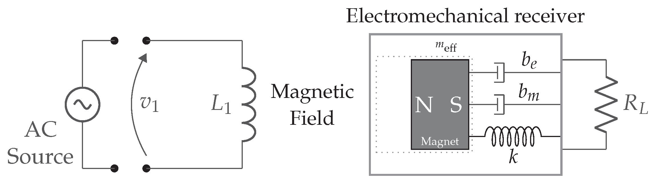
2.4. Electrodynamic Coupling
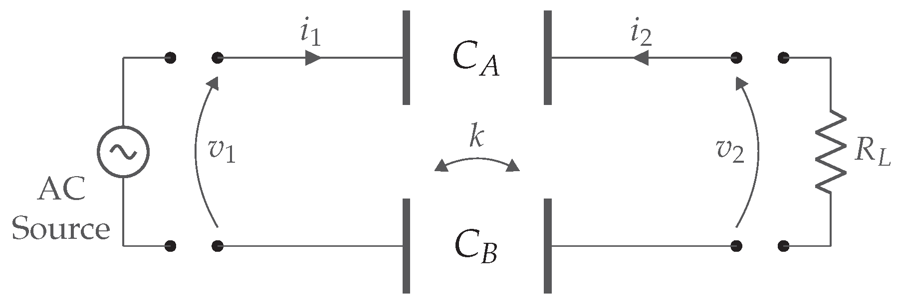
2.5. Capacitive Coupling
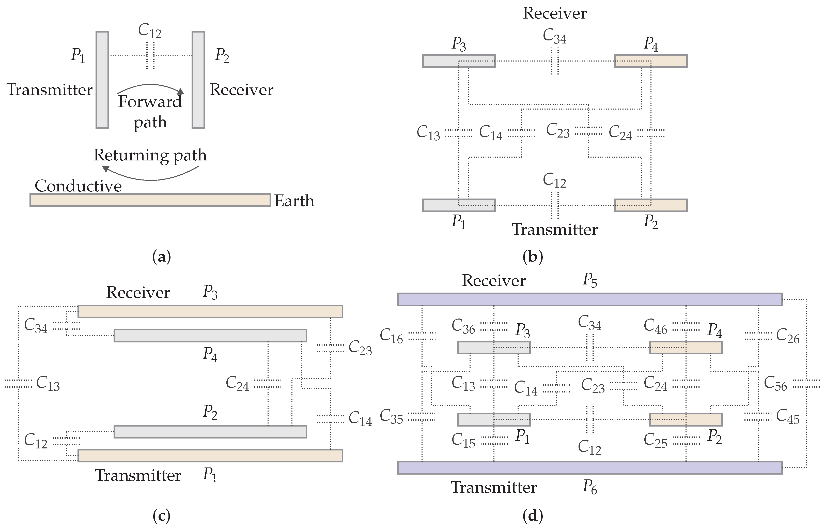
2.5.1. Plate Structures
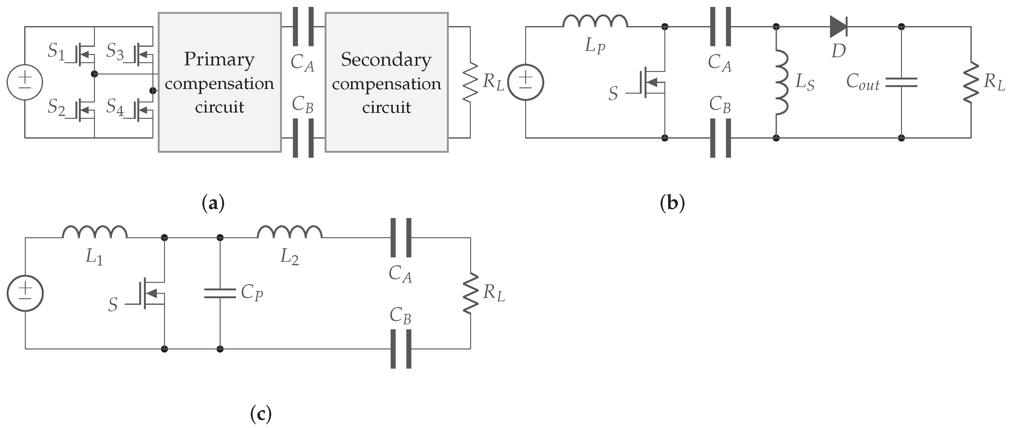
2.5.2. Circuit Topologies
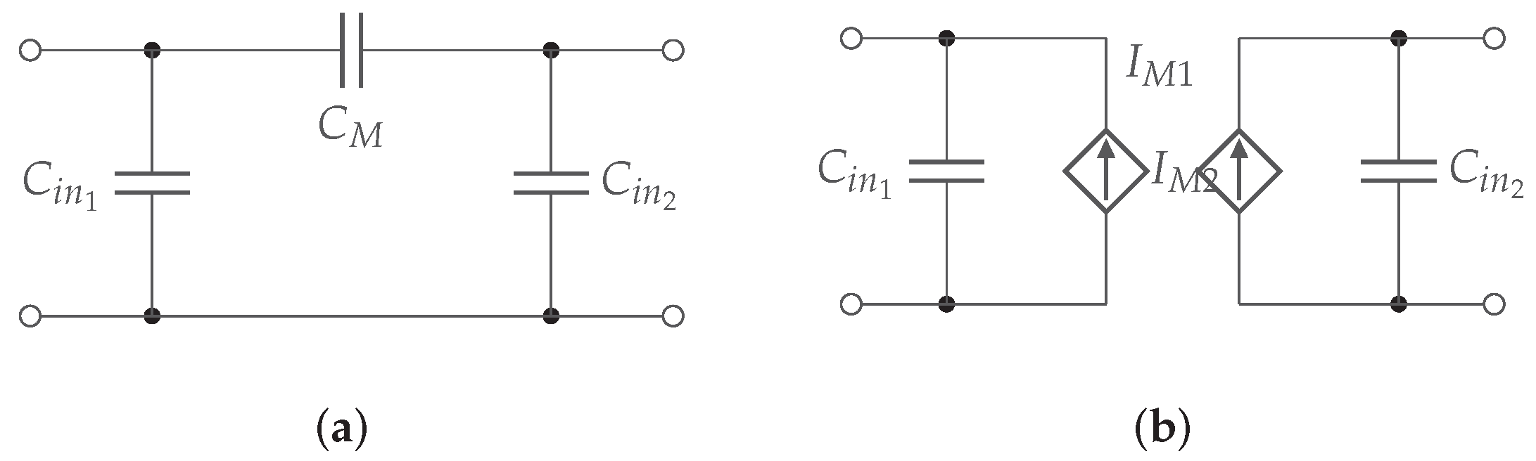
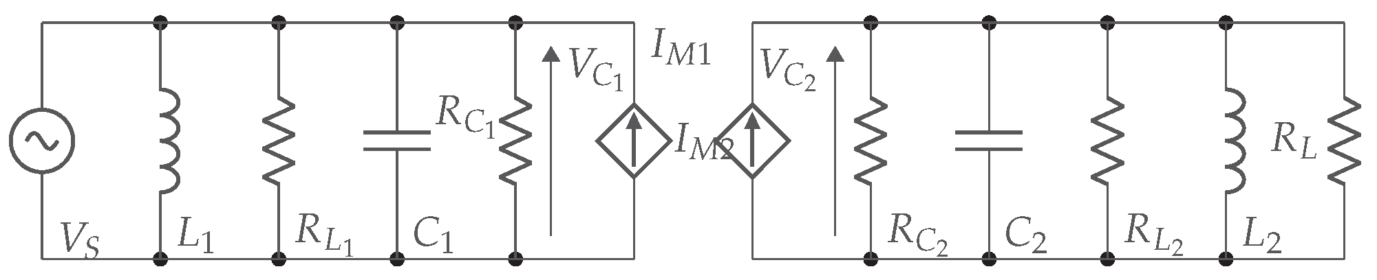
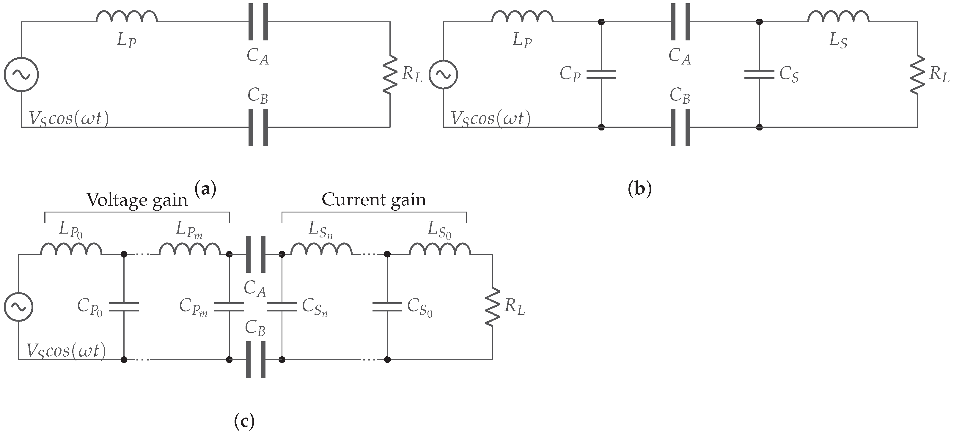
2.5.3. Compensation Circuits
3. Electromagnetic Uncoupled Technologies
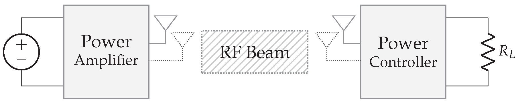
3.1. RF Power Transfer
3.2. Laser Power Transfer (LPT)
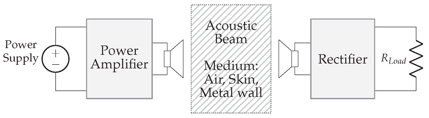
4. Acoustic Technologies
4.1. Biomedical
4.2. Metal Wall
4.3. Air
5. Range, Power, and Efficiency-Increasing Technologies
5.1. Beamforming
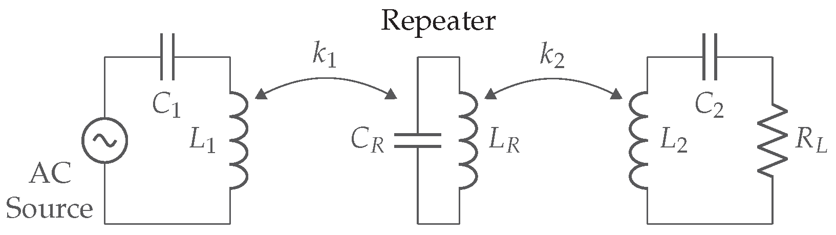
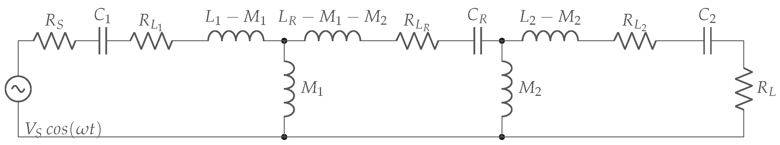
5.2. Repeaters
5.2.1. Magnetic Field Repeater
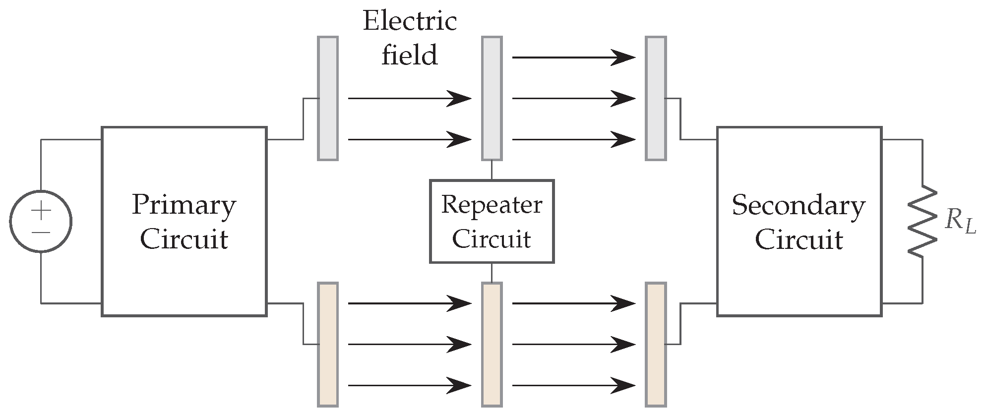
5.2.2. Electric Field Repeater
5.3. Energy Sources Carried by Unmanned Vehicles (UVs)
5.4. Favorable Propagation Medium
5.4.1. Inductive Power Transfer
5.4.2. Capacitive Power Transfer
6. Standards and Commercial Solutions
6.1. Inductive and Magnetic Resonance Coupling
6.1.1. Wireless Power Consortium
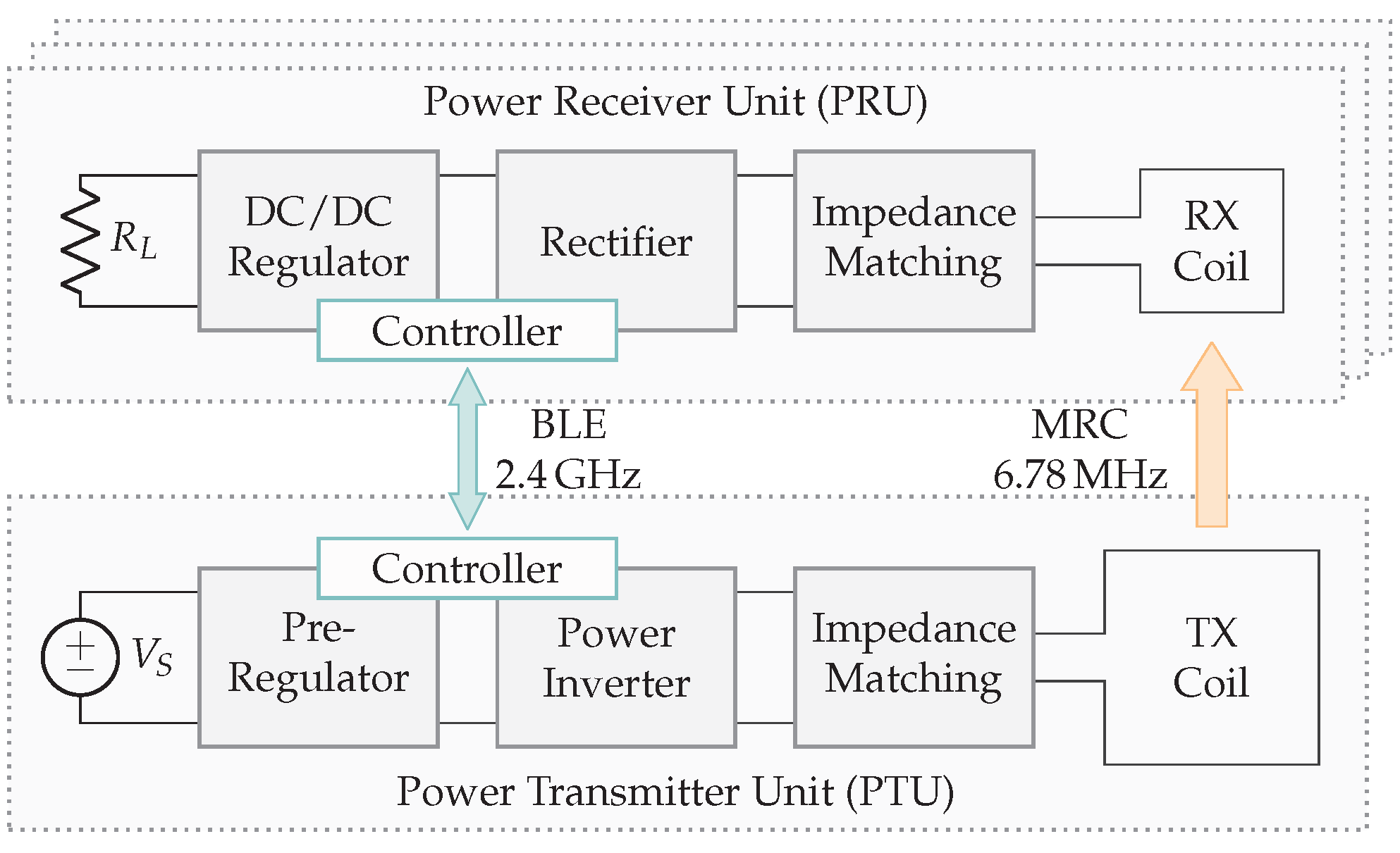
6.1.2. AirFuel (Alliance) Resonant
6.1.3. Wireless Charging Specification (WLC)
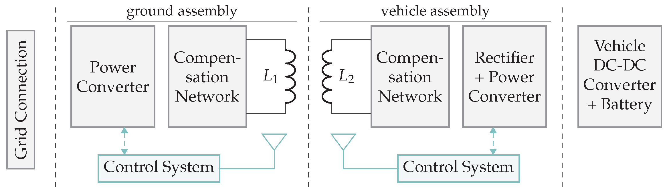
6.1.4. Standards for Automotive
6.1.5. Proprietary Solutions
6.2. Capacitive Coupled Systems
6.2.1. ARIB Standard
6.2.2. Murata
6.2.3. Eggtronic
6.2.4. Solace Power
6.3. Radio Frequency Power Transfer Systems
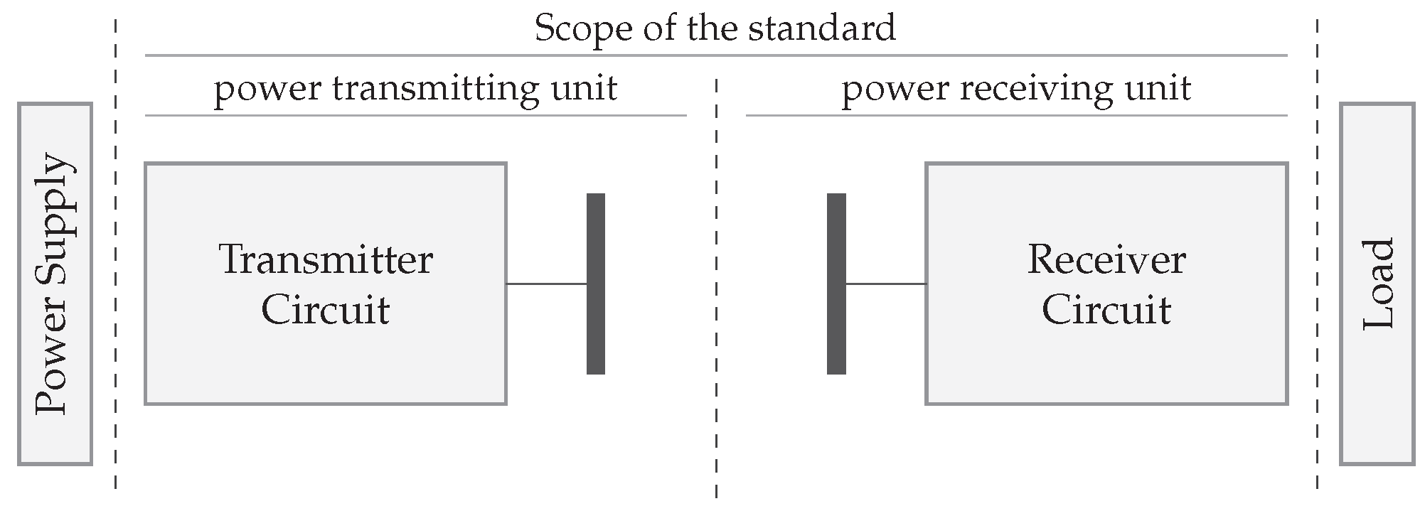
6.3.1. Airfuel RF (Alliance)
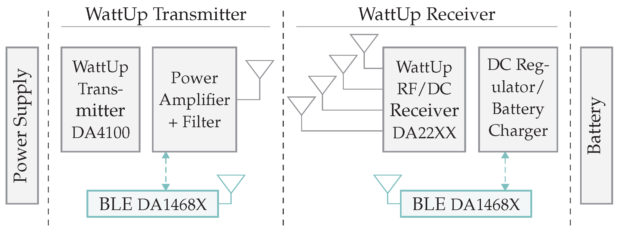
6.3.2. Ossia Inc. and ARCHOS
6.3.3. Semiconductor Manufacturers
6.3.4. EMROD
6.4. Light or Lasers Power Transfer Systems
6.4.1. WiCharge
6.4.2. PowerLight Techologies
7. Safety and Regulatory Context
7.1. Exposure to Electric Fields
7.2. Exposure to Magnetic Fields
7.3. Exposure to Electromagnetic Fields
- Thermal effects: heating of the biological tissue and overall increase in body temperature at frequencies .
- Non-thermal effects: nerve stimulation for frequencies up to 10 .
7.4. Exposure to Ultrasound
7.4.1. Tissue
7.4.2. Air
7.5. Exposure to Laser Beams
8. Implementation and Operational Challenges
8.1. Alignment Challenges
8.2. Localization Challenges
8.3. Challenges at High Power
8.3.1. Standardization
8.3.2. Electromagnetic Compatibility
- The amount of transferred power can be controlled by adjusting the duty cycle of the PWM signal in the inverter. This change can result in the loss of zero voltage switching off the power switch and cause high voltage changes in time . Subsequently, a changing magnetic and electric field is created, which carries the high . The fields around conducting components cause common-mode currents to flow from the system to the environment and back via the mains. This results in conducted interference or, more precisely, common-mode interference.
- Radiated EMI can be induced by switching large currents in the inverter, which cause large current changes in time . Furthermore, radiated EMI can also be caused by the leakage field of the inductors, due to poor coupling between transmitter and receiver.
8.3.3. Heat Dissipation at High Power Wireless Charging
9. Use Cases—Technology Mapping Catalog
9.1. Living and Working Environments
9.2. Environmental Monitoring, Industry 4.0, and Logistics
10. Current Gap and Future Trends
10.1. Electromagnetic Coupled: Gains and Trends
10.2. Electromagnetic Uncoupled: Gains and Trends
11. Conclusions
Author Contributions
Funding
Acknowledgments
Conflicts of Interest
Acronyms and Glossaries
| AGV | automated guided vehicle |
| EV | electric vehicle |
| FOD | foreign object detection |
| LOD | live object detection |
| PD | position detection |
| WPT | wireless power transfer |
| IR | infrared |
| EMI | electromagnetic interference |
| IEC | International Electrotechnical Commission |
| LPT | laser power transfer |
| HILPB | high-intensity laser power beam |
| PV | photovoltaic |
| WPC | Wireless Power Consortium |
| RFID | radio frequency identification |
| WLC | wireless charging specification |
| MCU | microcontroller unit |
| CPT | capacitive power transfer |
| HF | high frequency |
| NFC | near-field communication |
| PCB | printed circuit board |
| APT | acoustic power transfer |
| FCC | Federal Communications Commission |
| NCRP | National Council on Radiation Protection and Measurements |
| IEEE | Institute of Electrical and Electronics Engineers |
| ICNIRP | International Commission on Non-Ionizing Radiation Protection |
| SAR | specific energy absorption rate |
| SWIPT | simultaneous wireless information and power transmission |
| US | ultrasound |
| LIDAR | light detection and ranging |
| PEV | plug-in electric vehicle |
| EADS | European Aeronautic Defence and Space Company |
| UV | unmanned vehicle |
| UAV | unmanned aerial vehicle |
| UGV | unmanned ground vehicle |
| ISM | Industrial, Scientific, and Medical |
| IPT | inductive power transfer |
| BLE | Bluetooth Low Energy |
| MRC | magnetic resonance coupling |
| RFEH | radio frequency energy harvesting |
| RF | radio frequency |
| RFPT | radio frequency power transfer |
| SMPS | switched-mode power supply |
| EM | electromagnetic |
| LoS | line of sight |
| SEPIC | single-ended primary-inductor converter |
| EMC | electromagnetic compatibility |
| DC | direct current |
| MOSFET | metal-oxide-semiconductor field-effect transistor |
| GaN | gallium nitride |
| FET | field-effect transistor |
| VCO | voltage-controlled oscillator |
| IC | integrated circuit |
| S-BAR | semi-bridgeless active rectifier |
| LDO | low-dropout regulator |
| CC | constant current |
| CV | constant voltage |
| UUV | unmanned underwater vehicle |
| PVCC | photovoltaic cavity converter |
| SSPS | space solar power systems |
| ASK | amplitude-shift keying |
| OWPT | optical wireless power transmission |
| DLC | distributed laser charging |
| ZVS | zero voltage switching |
| PVC | polyvinyl chloride |
| PTU | power transmitting unit |
| PRU | power receiving unit |
| PHEV | plug-in hybrid electric vehicles |
| SAE | society of automotive engineers |
| VCCS | voltage controlled current sources |
| IMD | implantable medical device |
| LEV | light electric vehicle |
| VA | vehicle assembly |
| GA | ground assembly |
| IoT | Internet of Things |
| KVL | Kirchhoff’s voltage law |
| SiC | silicon carbide |
| WBG | wide band gap |
| SHM | structural health monitoring |
| NDE | non-destructive evaluation |
| ODPM | one dimension propagation model |
| CSI | channel state information |
| ARIB | Association of Radio Industries and Businesses |
| EIRP | effective isotropic radiated power |
| ISO | International Organization for Standardization |
| GNSS | global navigation satellite system |
| PZT | lead zirconate titanate |
| PVDF | polyvinylidene fluoride |
| FSK | frequency-shift keying |
| DWPT | dynamic wireless power transfer |
| PAPR | peak-to-average power ratio |
| BOM | bill of materials |
| OPA | optical phased arrays |
References
- Agarwal, K.; Jegadeesan, R.; Guo, Y.X.; Thakor, N.V. Wireless Power Transfer Strategies for Implantable Bioelectronics. IEEE Rev. Biomed. Eng. 2017, 10, 136–161. [Google Scholar] [CrossRef] [PubMed]
- Wireless Power Consortium. Qi Specification Power Delivery; V1.3.; Wireless Power Consortium: Piscataway, NJ, USA, 2021. [Google Scholar]
- Standard IEC 63028:2017; Wireless Power Transfer Airfuel Alliance Resonant Baseline System Specification (BSS). International Organization for Standardization: Geneva, Switzerland, 2017.
- Raab, F.; Asbeck, P.; Cripps, S.; Kenington, P.; Popovic, Z.; Pothecary, N.; Sevic, J.; Sokal, N. Power amplifiers and transmitters for RF and microwave. IEEE Trans. Microw. Theory Tech. 2002, 50, 814–826. [Google Scholar] [CrossRef] [Green Version]
- Microsemi, P. Gallium Nitride (GaN) Versus Silicon Carbide (SiC) In the High Frequency (RF) and Power Switching Applications; Digikey: Thief River Falls, MN, USA, 2014. [Google Scholar]
- Schuylenbergh, K.; Puers, R. (Eds.) Inductive Powering; Analog Circuits and Signal Processing; Springer: Dordrecht, The Netherlands, 2009. [Google Scholar] [CrossRef]
- Mai, R.; Liu, Y.; Li, Y.; Yue, P.; Cao, G.; He, Z. An Active-Rectifier-Based Maximum Efficiency Tracking Method Using an Additional Measurement Coil for Wireless Power Transfer. IEEE Trans. Power Electron. 2018, 33, 716–728. [Google Scholar] [CrossRef]
- Cochran, S.; Costinett, D. Frequency Synchronization and Control for a 6.78 MHz WPT Active Rectifier. In Proceedings of the 2018 IEEE 19th Workshop on Control and Modeling for Power Electronics (COMPEL), Padua, Italy, 25–28 June 2018; pp. 1–7. [Google Scholar] [CrossRef]
- Colak, K.; Asa, E.; Bojarski, M.; Czarkowski, D.; Onar, O.C. A Novel Phase-Shift Control of Semibridgeless Active Rectifier for Wireless Power Transfer. IEEE Trans. Power Electron. 2015, 30, 6288–6297. [Google Scholar] [CrossRef]
- Ahn, D.; Hong, S. A Study on Magnetic Field Repeater in Wireless Power Transfer. IEEE Trans. Ind. Electron. 2013, 60, 360–371. [Google Scholar] [CrossRef]
- Rindorf, L.; Lading, L.; Breinbjerg, O. Resonantly coupled antennas for passive sensors. In Proceedings of the 2008 IEEE Sensors, Lecce, Italy, 26–29 October 2008; pp. 1611–1614. [Google Scholar] [CrossRef]
- Baker, M.W.; Sarpeshkar, R. Feedback Analysis and Design of RF Power Links for Low-Power Bionic Systems. IEEE Trans. Biomed. Circuits Syst. 2007, 1, 28–38. [Google Scholar] [CrossRef]
- Challa, V.R.; Mur-Miranda, J.O.; Arnold, D.P. Wireless power transmission to an electromechanical receiver using low-frequency magnetic fields. Smart Mater. Struct. 2012, 21, 115017. [Google Scholar] [CrossRef]
- Mur-Miranda, J.O.; Cheng, S.; Arnold, D.P. Improving the efficiency of electrodynamic wireless power transmission. In Proceedings of the 2013 7th European Conference on Antennas and Propagation (EuCAP), Gothenburg, Sweden, 8–12 April 2013; pp. 2848–2852. [Google Scholar]
- Lecluyse, C.; Minnaert, B.; Kleemann, M. A Review of the Current State of Technology of Capacitive Wireless Power Transfer. Energies 2021, 14, 5862. [Google Scholar] [CrossRef]
- Dai, J.; Ludois, D.C. A Survey of Wireless Power Transfer and a Critical Comparison of Inductive and Capacitive Coupling for Small Gap Applications. IEEE Trans. Power Electron. 2015, 30, 6017–6029. [Google Scholar] [CrossRef]
- Minnaert, B.; Mastri, F.; Mongiardo, M.; Costanzo, A.; Stevens, N. Constant capacitive wireless power transfer at variable coupling. In Proceedings of the 2018 IEEE MTT-S International Wireless Symposium (IWS), Chengdu, China, 6–10 May 2018; pp. 1–4. [Google Scholar] [CrossRef]
- Lu, F.; Zhang, H.; Mi, C. A Review on the Recent Development of Capacitive Wireless Power Transfer Technology. Energies 2017, 10, 1752. [Google Scholar] [CrossRef] [Green Version]
- Zhang, H.; Lu, F.; Hofmann, H.; Liu, W.; Mi, C. A 4-Plate Compact Capacitive Coupler Design and Compensated Topology for Capacitive Power Transfer in Electric Vehicle Charging Applications. IEEE Trans. Power Electron. 2016, 31, 8541–8551. [Google Scholar] [CrossRef]
- Lu, F.; Zhang, H.; Mi, C. A Two-Plate Capacitive Wireless Power Transfer System for Electric Vehicle Charging Applications. IEEE Trans. Power Electron. 2018, 33, 964–969. [Google Scholar] [CrossRef]
- Lu, X.; Wang, P.; Niyato, D.; Kim, D.I.; Han, Z. Wireless Charging Technologies: Fundamentals, Standards, and Network Applications. IEEE Commun. Surv. Tutor. 2016, 18, 1413–1452. [Google Scholar] [CrossRef] [Green Version]
- Komaru, T.; Akita, H. Positional characteristics of capacitive power transfer as a resonance coupling system. In Proceedings of the 2013 IEEE Wireless Power Transfer (WPT), Perugia, Italy, 15–16 May 2013; pp. 218–221. [Google Scholar] [CrossRef]
- Zhang, H.; Lu, F.; Hofmann, H.; Liu, W.; Mi, C.C. Six-Plate Capacitive Coupler to Reduce Electric Field Emission in Large Air-Gap Capacitive Power Transfer. IEEE Trans. Power Electron. 2018, 33, 665–675. [Google Scholar] [CrossRef]
- Muharam, A.; Ahmad, S.; Hattori, R. Scaling-Factor and Design Guidelines for Shielded-Capacitive Power Transfer. Energies 2020, 13, 4240. [Google Scholar] [CrossRef]
- Muharam, A.; Ahmad, S.; Hattori, R.; Hapid, A. 13.56 MHz Scalable Shielded-Capacitive Power Transfer for Electric Vehicle Wireless Charging. In Proceedings of the 2020 IEEE PELS Workshop on Emerging Technologies: Wireless Power Transfer (WoW), Seoul, Korea, 15–19 November 2020; pp. 298–303. [Google Scholar] [CrossRef]
- Ahmad, S.; Hattori, R.; Muharam, A. Generalized Circuit Model of Shielded Capacitive Power Transfer. Energies 2021, 14, 2826. [Google Scholar] [CrossRef]
- Jiang, C.; Chau, K.T.; Liu, C.; Lee, C.H.T. An Overview of Resonant Circuits for Wireless Power Transfer. Energies 2017, 10, 894. [Google Scholar] [CrossRef]
- Ekbote, A.; Zinger, D.S. Comparison of class E and half bridge inverters for use in electronic ballasts. In Proceedings of the 2006 IEEE Industry Applications Conference Forty-First IAS Annual Meeting, Tampa, FL, USA, 8–12 October 2006; pp. 2198–2201. [Google Scholar] [CrossRef]
- Kodeeswaran, S.; Gayathri, M.N. Performance Investigation of Capacitive Wireless Charging Topologies for Electric Vehicles. In Proceedings of the 2021 International Conference on Innovative Trends in Information Technology (ICITIIT), Kottayam, India, 11–12 February 2021; pp. 1–6. [Google Scholar] [CrossRef]
- Dai, J.; Ludois, D.C. Single Active Switch Power Electronics for Kilowatt Scale Capacitive Power Transfer. IEEE J. Emerg. Sel. Top. Power Electron. 2015, 3, 315–323. [Google Scholar] [CrossRef]
- Andreycak, B. Zero voltage switching resonant power conversion. In UNITRODE Power Supply Design Seminar SEM-700; UNITRODE: Merrimack, NH, USA, 1990. [Google Scholar]
- Aldhaher, S.; Luk, P.C.K.; Bati, A.; Whidborne, J.F. Wireless Power Transfer Using Class E Inverter With Saturable DC-Feed Inductor. IEEE Trans. Ind. Appl. 2014, 50, 2710–2718. [Google Scholar] [CrossRef] [Green Version]
- Gaalaas, E. Class D Audio Amplifiers: What, Why, and How. Available online: https://www.analog.com/en/analog-dialogue/articles/class-d-audio-amplifiers.html (accessed on 10 February 2022).
- Rozario, D.; Azeez, N.A.; Williamson, S.S. Analysis and design of coupling capacitors for contactless capacitive power transfer systems. In Proceedings of the 2016 IEEE Transportation Electrification Conference and Expo, ITEC 2016, Dearborn, MI, USA, 27–29 June 2016. [Google Scholar] [CrossRef]
- Liu, C.; Hu, A.P.; Covic, G.A.; Nair, N.K.C. Comparative Study of CCPT Systems With Two Different Inductor Tuning Positions. IEEE Trans. Power Electron. 2012, 27, 294–306. [Google Scholar] [CrossRef]
- Kuroda, S.; Imura, T. Derivation and comparison of efficiency and power in non-resonant and resonant circuit of capacitive power transfer. In Proceedings of the 2020 IEEE PELS Workshop on Emerging Technologies: Wireless Power Transfer, WoW 2020, Seoul, Korea, 15–19 November 2020; pp. 152–157. [Google Scholar] [CrossRef]
- Sun, H.; Yin, M.; Wei, W.; Li, J.; Wang, H.; Jin, X. MEMS based energy harvesting for the Internet of Things: A survey. Microsyst. Technol. 2018, 24, 2853–2869. [Google Scholar] [CrossRef]
- Cansiz, M.; Altinel, D.; Kurt, G.K. Efficiency in RF energy harvesting systems: A comprehensive review. Energy 2019, 174, 292–309. [Google Scholar] [CrossRef]
- Lu, X.; Wang, P.; Niyato, D.; Kim, D.I.; Han, Z. Wireless Networks With RF Energy Harvesting: A Contemporary Survey. IEEE Commun. Surv. Tutor. 2015, 17, 757–789. [Google Scholar] [CrossRef] [Green Version]
- Muncuk, U.; Alemdar, K.; Sarode, J.D.; Chowdhury, K.R. Multiband Ambient RF Energy Harvesting Circuit Design for Enabling Batteryless Sensors and IoT. IEEE Internet Things J. 2018, 5, 2700–2714. [Google Scholar] [CrossRef]
- Pinuela, M.; Mitcheson, P.D.; Lucyszyn, S. Ambient RF Energy Harvesting in Urban and Semi-Urban Environments. IEEE Trans. Microw. Theory Tech. 2013, 61, 2715–2726. [Google Scholar] [CrossRef]
- Sun, H.; Guo, Y.x.; He, M.; Zhong, Z. A Dual-Band Rectenna Using Broadband Yagi Antenna Array for Ambient RF Power Harvesting. IEEE Antennas Wirel. Propag. Lett. 2013, 12, 918–921. [Google Scholar] [CrossRef]
- Ponnimbaduge Perera, T.D.; Jayakody, D.N.K.; Sharma, S.K.; Chatzinotas, S.; Li, J. Simultaneous Wireless Information and Power Transfer (SWIPT): Recent Advances and Future Challenges. IEEE Commun. Surv. Tutor. 2018, 20, 264–302. [Google Scholar] [CrossRef] [Green Version]
- Clerckx, B.; Varasteh, M. Fundamentals of Signal Design for WPT and SWIPT. In Wireless Information and Power Transfer; John Wiley & Sons, Ltd.: Hoboken, NJ, USA, 2018; Chapter 2; pp. 17–37. [Google Scholar] [CrossRef]
- Buyle, C.; Cox, B.; Van der Perre, L.; De Strycker, L. A Multi-band Solution for Interacting with Energy-Neutral Devices. arXiv 2021, arXiv:2112.08855. [Google Scholar]
- A. Balanis, C. Antenna Theory: Analysis and Design, 3rd ed.; John Wiley and Sons, Inc.: Hoboken, NJ, USA, 2005; pp. 92–95. [Google Scholar]
- Nguyen, D.H.; Qin, C.; Matsushima, T.; Adachi, C. Thing-to-Thing Optical Wireless Power Transfer Based on Metal Halide Perovskite Transceivers. arXiv 2020, arXiv:abs/2009.06163. [Google Scholar]
- Höhn, O.; Walker, A.W.; Bett, A.W.; Helmers, H. Optimal laser wavelength for efficient laser power converter operation over temperature. Appl. Phys. Lett. 2016, 108, 241104. [Google Scholar] [CrossRef]
- Jin, K.; Zhou, W. Wireless Laser Power Transmission: A Review of Recent Progress. IEEE Trans. Power Electron. 2019, 34, 3842–3859. [Google Scholar] [CrossRef]
- Mohammadnia, A.; M. Ziapour, B.; Ghaebi, H.; Khooban, M.H. Feasibility assessment of next-generation drones powering by laser-based wireless power transfer. Opt. Laser Technol. 2021, 143, 107283. [Google Scholar] [CrossRef]
- Solymar, L.; Walsh, D.; Syms, R.R.A. Principles of Semiconductor Devices; Oxford University Press: Oxford, UK, 2018. [Google Scholar] [CrossRef]
- Emery, W.; Camps, A. Atmosphere Applications. In Introduction to Satellite Remote Sensing; Emery, W., Camps, A., Eds.; Elsevier: Amsterdam, The Netherlands, 2017; pp. 597–636. [Google Scholar] [CrossRef]
- Bernath, P.F. Spectra of Atoms and Molecules; Oxford University Press: New York, NY, USA, 1995. [Google Scholar]
- Geyer, C. Analysis of Wireless Transmission of Power for Physical Security Use; Technical Report; Sandia National Lab.: Albuquerque, NM, USA, 2019. [CrossRef]
- Ghasvarianjahromi, S.; Karbalayghareh, M.; Diamantoulakis, P.D.; Karagiannidis, G.K.; Uysal, M. Simultaneous Lightwave Information and Power Transfer in Underwater Visible Light Communications. In Proceedings of the 2019 IEEE 30th Annual International Symposium on Personal, Indoor and Mobile Radio Communications (PIMRC), Istanbul, Turkey, 8–11 September 2019; pp. 1–6. [Google Scholar] [CrossRef]
- Steinsiek, F.; Weber, K.; Foth, W.; Foth, H.; Schafer, C. Wireless power transmission technology development and demonstrations. In Proceedings of the 2nd International Conference on Recent Advances in Space Technologies, Istanbul, Turkey, 9–11 June 2005; pp. 140–149. [Google Scholar] [CrossRef]
- Blackwell, T. Recent demonstrations of Laser power beaming at DFRC and MSFC. AIP Conf. Proc. 2005, 766, 73. [Google Scholar] [CrossRef]
- Kawashima, N.; Takeda, K.; Matsuoka, H.; Fujii, Y.; Yamamoto, M. Laser Energy Transmission for a Wireless Energy Supply to Robots. In Proceedings of the 22nd International Symposium on Automation and Robotics in Construction (IAARC), Ferrara, Italy, 11–14 September 2005. [Google Scholar] [CrossRef] [Green Version]
- Takeda, K.; Kawashima, N.; Yabe, K. Laser Energy Transmission to a Small-Unmanned Aerial Vehicle. Space Technol. Jpn. 2008, 7, 27–32. [Google Scholar] [CrossRef] [Green Version]
- He, T.; Yang, S.H.; Zhang, H.Y.; Zhao, C.M.; Zhang, Y.C.; Xu, P.; Muñoz, M.A. High-Power High-Efficiency Laser Power Transmission at 100 m Using Optimized Multi-Cell GaAs Converter. Chin. Phys. Lett. 2014, 31, 104203. [Google Scholar] [CrossRef] [Green Version]
- Ortabasi, U.; Friedman, H. Powersphere: A Photovoltaic Cavity Converter for Wireless Power Transmission using High Power Lasers. In Proceedings of the 2006 IEEE 4th World Conference on Photovoltaic Energy Conference, Waikoloa, HI, USA, 7–12 May 2006; pp. 126–129. [Google Scholar] [CrossRef]
- Sung-Man Kim, S.M.K.; Jongmyeong Choi, J.C.; Hyunwoo Jung, H.J. Experimental demonstration of underwater optical wireless power transfer using a laser diode. Chin. Opt. Lett. 2018, 16, 080101. [Google Scholar] [CrossRef] [Green Version]
- Mori, M.; Kagawa, H.; Nagayama, H.; Saito, Y. Current status of a study on hydrogen production with space solar power systems (SSPS). In Proceedings of the Solar Power from Space (SPS ’04), Granada, Spain, 30 June–2 July 2004. [Google Scholar]
- Liu, Q.; Wu, J.; Xia, P.; Zhao, S.; Chen, W.; Yang, Y.; Hanzo, L. Charging Unplugged: Will Distributed Laser Charging for Mobile Wireless Power Transfer Work? IEEE Veh. Technol. Mag. 2016, 11, 36–45. [Google Scholar] [CrossRef]
- Zhang, Q.; Fang, W.; Liu, Q.; Wu, J.; Xia, P.; Yang, L. Distributed Laser Charging: A Wireless Power Transfer Approach. IEEE Internet Things J. 2018, 5, 3853–3864. [Google Scholar] [CrossRef] [Green Version]
- Roes, M.G.L.; Duarte, J.L.; Hendrix, M.A.M.; Lomonova, E.A. Acoustic Energy Transfer: A Review. IEEE Trans. Ind. Electron. 2013, 60, 242–248. [Google Scholar] [CrossRef]
- Joung, Y.H. Development of Implantable Medical Devices: From an Engineering Perspective. Int. Neurourol. J. 2013, 17, 98. [Google Scholar] [CrossRef]
- Basaeri, H.; Christensen, D.B.; Roundy, S. A review of acoustic power transfer for bio-medical implants. Smart Mater. Struct. 2016, 25, 123001. [Google Scholar] [CrossRef]
- Denisov, A.; Yeatman, E. Ultrasonic vs. Inductive Power Delivery for Miniature Biomedical Implants. In Proceedings of the 2010 International Conference on Body Sensor Networks, Singapore, 7–9 June 2010; pp. 84–89. [Google Scholar] [CrossRef]
- Guo, S.; Duan, X.; Xie, M.; Aw, K.C.; Xue, Q. Composites, Fabrication and Application of Polyvinylidene Fluoride for Flexible Electromechanical Devices: A Review. Micromachines 2020, 11, 1076. [Google Scholar] [CrossRef]
- Rathod, V.T. A Review of Acoustic Impedance Matching Techniques for Piezoelectric Sensors and Transducers. Sensors-basel. 2020, 20, 4051. [Google Scholar] [CrossRef]
- Song, S.H.; Kim, A.; Ziaie, B. Omnidirectional Ultrasonic Powering for Millimeter-Scale Implantable Devices. IEEE Trans. Biomed. Eng. 2015, 62, 2717–2723. [Google Scholar] [CrossRef]
- Sherrit, S.; Badescu, M.; Bao, X.; Bar-Cohen, Y.; Chang, Z. Efficient electromechanical network model for wireless acoustic-electric feed-throughs. Proc. SPIE 2005, 5758. [Google Scholar] [CrossRef]
- Tseng, V.F.G.; Bedair, S.S.; Lazarus, N. Acoustic Power Transfer and Communication With a Wireless Sensor Embedded Within Metal. IEEE Sensors J. 2018, 18, 5550–5558. [Google Scholar] [CrossRef]
- Yang, D.X.; Hu, Z.; Zhao, H.; Hu, H.F.; Sun, Y.Z.; Hou, B.J. Through-Metal-Wall Power Delivery and Data Transmission for Enclosed Sensors: A Review. Sensors 2015, 15, 31581–31605. [Google Scholar] [CrossRef]
- Lawry, T.J.; Saulnier, G.J.; Ashdown, J.D.; Wilt, K.R.; Scarton, H.A.; Pascarelle, S.; Pinezich, J.D. Penetration-free system for transmission of data and power through solid metal barriers. In Proceedings of the MILCOM 2011 Military Communications Conference, Baltimore, MD, USA, 7–10 November 2011; pp. 389–395. [Google Scholar] [CrossRef]
- Bao, X.; Biederman, W.; Sherrit, S.; Badescu, M.; Bar-Cohen, Y.; Jones, C.; Aldrich, J.; Chang, Z. High-power piezoelectric acoustic-electric power feedthru for metal walls. In Proceedings of the Industrial and Commercial Applications of Smart Structures Technologies 2008, San Diego, CA, USA, 9–13 March 2008; Volume 6930. [Google Scholar] [CrossRef]
- Hu, Y.; Zhang, X.; Yang, J.; Jiang, Q. Transmitting electric energy through a metal wall by acoustic waves using piezoelectric transducers. IEEE Trans. Ultrason. Ferroelectr. Freq. Control 2003, 50, 773–781. [Google Scholar] [CrossRef] [PubMed]
- Wilt, K.; Lawry, T.; Scarton, H.; Saulnier, G. One-dimensional pressure transfer models for acoustic transmission channels. J. Sound Vib. 2015, 352, 158–173. [Google Scholar] [CrossRef]
- Mason, W. Equivalent electromechanical representation of trapped energy transducers. Proc. IEEE 1969, 57, 1723–1734. [Google Scholar] [CrossRef]
- Krimholtz, R.; Leedom, D.; Matthaei, G. New equivalent circuits for elementary piezoelectric transducers. Electron. Lett. 1970, 6, 398. [Google Scholar] [CrossRef]
- Freychet, O.; Frassati, F.; Boisseau, S.; Garraud, N.; Gasnier, P.; Despesse, G. Analytical optimization of piezoelectric acoustic power transfer systems. Eng. Res. Express 2020, 2, 045022. [Google Scholar] [CrossRef]
- Roes, M. Exploring the potential of acoustic energy transfer. Ph.D. Thesis, Electrical Engineering, Eindhoven University of Technology, Eindhoven, The Netherlands, 2015. [Google Scholar]
- Rekhi, A.S.; Khuri-Yakub, B.T.; Arbabian, A. Wireless Power Transfer to Millimeter-Sized Nodes Using Airborne Ultrasound. IEEE Trans. Ultrason. Ferroelectr. Freq. Control 2017, 64, 1526–1541. [Google Scholar] [CrossRef]
- Yedavalli, P.S.; Riihonen, T.; Wang, X.; Rabaey, J.M. Far-Field RF Wireless Power Transfer with Blind Adaptive Beamforming for Internet of Things Devices. IEEE Access 2017, 5, 1743–1752. [Google Scholar] [CrossRef]
- Hajimiri, A.; Abiri, B.; Bohn, F.; Gal-Katziri, M.; Manohara, M.H. Dynamic Focusing of Large Arrays for Wireless Power Transfer and Beyond. IEEE J. Solid-State Circuits 2021, 56, 2077–2101. [Google Scholar] [CrossRef]
- Fan, X.; Ding, H.; Li, S.; Sanzari, M.; Zhang, Y.; Trappe, W.; Han, Z.; Howard, R.E. Energy-Ball: Wireless Power Transfer for Batteryless Internet of Things through Distributed Beamforming. Proc. ACM Interactive Mobile Wearable Ubiquitous Technol. 2018, 2, 65. [Google Scholar] [CrossRef]
- Gowda, V.R.; Yurduseven, O.; Lipworth, G.; Zupan, T.; Reynolds, M.S.; Smith, D.R. Wireless Power Transfer in the Radiative Near Field. IEEE Antennas Wirel. Propag. Lett. 2016, 15, 1865–1868. [Google Scholar] [CrossRef]
- Belo, D.; Ribeiro, D.C.; Pinho, P.; Borges Carvalho, N. A Selective, Tracking, and Power Adaptive Far-Field Wireless Power Transfer System. IEEE Trans. Microw. Theory Tech. 2019, 67, 3856–3866. [Google Scholar] [CrossRef]
- Hui, Q.; Jin, K.; Zhu, X. Directional Radiation Technique for Maximum Receiving Power in Microwave Power Transmission System. IEEE Trans. Ind. Electron. 2020, 67, 6376–6386. [Google Scholar] [CrossRef]
- Massa, A.; Oliveri, G.; Viani, F.; Rocca, P. Array Designs for Long-Distance Wireless Power Transmission: State-of-the-art and Innovative Solutions. Proc. IEEE 2013, 101, 1464–1481. [Google Scholar] [CrossRef]
- Shen, S.; Clerckx, B. Beamforming Optimization for MIMO Wireless Power Transfer With Nonlinear Energy Harvesting: Rf Combining Versus DC Combining. IEEE Trans. Wireless Commun. 2021, 20, 199–213. [Google Scholar] [CrossRef]
- Tseng, V.F.G.; Bedair, S.S.; Lazarus, N. Phased Array Focusing for Acoustic Wireless Power Transfer. IEEE Trans. Ultrason. Ferroelectr. Freq. Control 2018, 65, 39–49. [Google Scholar] [CrossRef]
- Jadidian, J.; Katabi, D. Magnetic MIMO. In Proceedings of the 20th Annual International Conference on Mobile Computing and Networking, Maui, HI, USA, 7–11 September 2014; pp. 495–506. [Google Scholar] [CrossRef]
- Sun, H.; Lin, H.; Zhu, F.; Gao, F. Magnetic Resonant Beamforming for Secured Wireless Power Transfer. IEEE Signal Process Lett. 2017, 24, 1173–1177. [Google Scholar] [CrossRef]
- Kim, K.; Kim, H.J.; Choi, J.W. Magnetic beamforming with non-coupling coil pattern for high efficiency and long distance wireless power transfer. In Proceedings of the 2017 IEEE Wireless Power Transfer Conference (WPTC), Taipei, Taiwan, 10–12 May 2017; pp. 1–4. [Google Scholar] [CrossRef]
- Kisseleff, S.; Akyildiz, I.F.; Gerstacker, W. Beamforming for Magnetic Induction Based Wireless Power Transfer Systems with Multiple Receivers. In Proceedings of the 2015 IEEE Global Communications Conference (GLOBECOM), San Diego, CA, USA, 6–10 December 2015; pp. 1–7. [Google Scholar] [CrossRef] [Green Version]
- Wan, K.C.; Xue, Q.; Liu, X.; Hui, S.Y. Passive Radio-Frequency Repeater for Enhancing Signal Reception and Transmission in a Wireless Charging Platform. IEEE Trans. Ind. Electron. 2014, 61, 1750–1757. [Google Scholar] [CrossRef]
- Kurs, A.; Karalis, A.; Moffatt, R.; Joannopoulos, J.D.; Fisher, P.; Soljačić, M. Wireless Power Transfer via Strongly Coupled Magnetic Resonances. Science 2007, 317, 83–86. [Google Scholar] [CrossRef] [Green Version]
- Zhang, H.; Lu, F.; Hofmann, H.; Liu, W.; Mi, C.C. An LC compensated electric field repeater for long distance capacitive power transfer. In Proceedings of the IEEE Energy Conversion Congress and Exposition (ECCE), Milwaukee, WI, USA, 18–22 September 2016; pp. 5–9. [Google Scholar] [CrossRef]
- Minnaert, B.; Monti, G.; Costanzo, A.; Mongiardo, M. Gain Expressions for Capacitive Wireless Power Transfer with One Electric Field Repeater. Electronics 2021, 10, 723. [Google Scholar] [CrossRef]
- Duarte, C.; Goncalves, F.; Silva, M.; Correia, V.; Pessoa, L.M. Experimental Evaluation of Coupling Coils for Underwater Wireless Power Transfer. In Proceedings of the 2019 IEEE Wireless Power Transfer Conference (WPTC), London, UK, 18–21 June 2019; pp. 557–560. [Google Scholar] [CrossRef]
- Mulders, J.V.; Crul, S.; Leenders, G.; Thoen, B.; der Perre, L.V. Bringing Energy to IoT Nodes: An Unmanned Vehicle for Wireless Power Transfer. In Proceedings of the 2019 IEEE Sensors Applications Symposium (SAS), Sophia Antipolis, France, 11–13 March 2019; pp. 1–5. [Google Scholar] [CrossRef]
- Van Mulders, J.; Leenders, G.; Callebaut, G.; De Strycker, L.; Van der Perre, L. Aerial Energy Provisioning for Massive Energy-Constrained IoT by UAVs. arXiv 2022, arXiv:2201.09786. [Google Scholar]
- Yao, Y.; Zhu, Z.; Huang, S.; Yue, X.; Pan, C.; Li, X. Energy Efficiency Characterization in Heterogeneous IoT System With UAV Swarms Based on Wireless Power Transfer. IEEE Access 2020, 8, 967–979. [Google Scholar] [CrossRef]
- Ahuir, J.V. Going Wireless with Magnetic Shielding; Application Note; Würth Elektronik: Niedernhall, Germany, 2013. [Google Scholar]
- Lecluyse, C.; Minnaert, B.; Ravyts, S.; Kleemann, M. Influence of a Medium on Capacitive Power Transfer Capability. In Proceedings of the IEEE Wireless Power Transfer Conference (WPTC), Bordeaux, France, 5–8 July 2022. to be published. [Google Scholar]
- Relative Permittivity—The Dielectric Constant. Available online: https://www.engineeringtoolbox.com/relative-permittivity-d_1660.html (accessed on 4 March 2022).
- Kesler, M. Wireless Charging of Electric Vehicles. In Proceedings of the 2018 IEEE Wireless Power Transfer Conference (WPTC), Montreal, QC, Canada, 3–7 June 2018. [Google Scholar] [CrossRef]
- AirFuel Is Cutting the Cord. Available online: https://airfuel.org/wireless-power/ (accessed on 10 February 2022).
- Das, H.; Rahman, M.; Li, S.; Tan, C. Electric vehicles standards, charging infrastructure, and impact on grid integration: A technological review. Renew. Sustain. Energy Rev. 2020, 120, 109618. [Google Scholar] [CrossRef]
- Wireless Power Transfer for Light-Duty Plug-in Electric Vehicles and Alignment Methodology. Available online: https://www.sae.org/standards/content/j2954_202010 (accessed on 10 February 2022).
- SAE J2954/2 Wireless Power Transfer & Alignment for Heavy Duty Applications. Available online: https://www.sae.org/standards/content/j2954/2/ (accessed on 10 February 2022).
- Be in Charge: Making EV Charging Easier Than Refueling. Available online: https://witricity.com/ (accessed on 10 February 2022).
- Triviño Cabrera, A.; González-González, J.M.; Aguado, J.A. Wireless Power Transfer for Electric Vehicles: Foundations and Design Approach; Power Systems; Springer International Publishing: Cham, Switzerland, 2020. [Google Scholar] [CrossRef]
- SAE International Approves TIR J2954 for PH/EV Wireless Charging; Targeting Finalized Standard by 2018. Available online: https://www.greencarcongress.com/2016/05/20160518-j2954.html (accessed on 10 February 2022).
- Standard IEC61980-1; Electric Vehicle Wireless Power Transfer (WPT) Systems. International Electrotechnical Commission: Geneva, Switzerland, 2020.
- SEMTECH Products Wireless Charging. Available online: https://www.semtech.com/products/wireless-charging/ (accessed on 10 February 2022).
- Wang, N.; Wu, J.; Dai, H. Bundle Charging: Wireless Charging Energy Minimization in Dense Wireless Sensor Networks. In Proceedings of the 2019 IEEE 39th International Conference on Distributed Computing Systems (ICDCS), Dallas, TX, USA, 7–10 July 2019. [Google Scholar] [CrossRef]
- Standard ARIB STD-T113; Wireless Power Transmission Systems. Association of Radio Industries and Businesses: Kasumigaseki, Japan, 2015.
- Capacitive Coupling Wireless Power Transmission System. Available online: https://corporate.murata.com/more_murata/techmag/metamorphosis16/productsmarket/wireless/ (accessed on 17 January 2022).
- Sheppard, P. GaN Enables Efficient and Compact Capacitive-Coupled Power Conversion. Available online: https://eepower.com/news/gan-enables-efficient-and-compact-capacitive-coupled-power-conversion/ (accessed on 17 January 2022).
- Modular Wireless Power Platform. Available online: https://www.solace.ca/technology (accessed on 16 February 2022).
- Wireless Charging 2.0. Available online: https://energous.com/ (accessed on 16 February 2022).
- ARCHOS and Ossia Partner to Bring Innovative Wirelessly Powered Consumer IoT Products to Market. Available online: https://blog.ossia.com/press/archos-and-ossia-partner-to-bring-innovative-wirelessly-powered-consumer-iot-products-to-market (accessed on 28 January 2022).
- Cota Real Wireless Power Earns FCC Approval. Available online: https://info.ossia.com/cota-real-wireless-power-earns-fcc-approval (accessed on 10 February 2022).
- Blain, L. NZ to Trial World-First Commercial Long-Range, Wireless Power Transmission. Available online: https://newatlas.com/energy/long-range-wireless-power-transmission-new-zealand-emrod/ (accessed on 10 February 2022).
- Thomson, H. Your questions answered. New Sci. 2019, 244, 9. [Google Scholar] [CrossRef]
- Charging Wireless and Touchless, Of Course. Available online: https://wi-charge.com/ (accessed on 10 February 2022).
- Lahmeri, M.A.; Kishk, M.A.; Alouini, M.S. Charging Techniques for UAV-Assisted Data Collection: Is Laser Power Beaming the Answer? IEEE Commun. Mag. 2022, 60, 50–56. [Google Scholar] [CrossRef]
- Hargis, L.; Botkin, J. PowerLight Corporation Lean Manufacturing, PV Manufacturing R&D Phase I Report: 6 December 2001–31 March 2003; Technical report; Office of Scientific and Technical Information (OSTI): Oak Ridge, TN, USA, 2005. [CrossRef] [Green Version]
- IEEE C95.1-2019; IEEE Standard for Safety Levels with Respect to Human Exposure to Electric, Magnetic, and Electromagnetic Fields, 0 Hz to 300 GHz. The Institute of Electrical and Electronics Engineers: New York, NY, USA, 2019.
- Ge, B.; Ludois, D.C.; Perez, R. The use of dielectric coatings in capacitive power transfer systems. In Proceedings of the 2014 IEEE Energy Conversion Congress and Exposition (ECCE), Pittsburgh, PA, USA, 14–18 September 2014; pp. 2193–2199. [Google Scholar] [CrossRef]
- Radio Frequency Safety. Available online: https://www.fcc.gov/engineering-technology/electromagnetic-compatibility-division/radio-frequency-safety/faq/rf-safety (accessed on 20 January 2022).
- International Commission on Non-Ionizing Radiation Protection. Guidelines for Limiting Exposure to Electromagnetic Fields (100 kHz to 300 GHz). Health Phys. 2020, 118, 483–524. [Google Scholar] [CrossRef]
- Lu, Y.; Ki, W.H. Power Amplifiers for WPT. In Analog Circuits and Signal Processing; Chapter Power Amplifiers for WPT; Springer: Singapore, 2017; pp. 143–157. [Google Scholar] [CrossRef]
- Charles, M.; Litwin, A.; Allal, D. RF power standard for low frequencies (100 kHz to 1 GHz). In Proceedings of the 2012 Conference on Precision Electromagnetic Measurements, Washington, DC, USA, 1–6 July 2012. [Google Scholar] [CrossRef]
- Duck, F.; Leighton, T. Frequency bands for ultrasound, suitable for the consideration of its health effects. J. Acoust. Soc. Am. 2018, 144, 2490–2500. [Google Scholar] [CrossRef] [Green Version]
- Fletcher, M.D.; Lloyd Jones, S.; White, P.R.; Dolder, C.N.; Lineton, B.; Leighton, T.G. Public exposure to ultrasound and very high-frequency sound in air. J Acoust Soc Am 2018, 144, 2554–2564. [Google Scholar] [CrossRef] [Green Version]
- Howard, C.Q.; Hansen, C.H.; Zander, A.C. Review of current recommendations for airborne ultrasound exposure limits. In Proceedings of the Acoustics 2005, Busselton, Australia, 9–11 November 2005. [Google Scholar]
- Leighton, T.G. Are some people suffering as a result of increasing mass exposure of the public to ultrasound in air? Proc. R. Soc. A Math. Phys. Eng. Sci. 2016, 472, 20150624. [Google Scholar] [CrossRef]
- Health Canada. Guidelines for the Safe Use of Ultrasound: Part II Industrial and Commercial Applications; Health Canada: Ottawa, ON, Canada, 1991.
- (Ultra) Sound Interfaces and Low Energy Integrated Sensors; Deliverable Report for D1.1.3, JU Grant Agreement 737487; Silense: Leuven, Belgium, 2018.
- Barat, K. Laser Safety; CRC Press: Boca Raton, FL, USA, 2014. [Google Scholar] [CrossRef]
- Standard IEC60825-1; Safety of Laser Products. International Electrotechnical Commission: Geneva, Switzerland, 2014.
- Standard ANSI Z-136; Safe Use of Lasers. American National Standards Institute: New York, NY, USA, 2014.
- Berman, S.M.; Greenhouse, D.S.; Bailey, I.L.; Clear, R.D.; Raasch, T.W. Human Electroretinogram Responses to Video Displays, Fluorescent Lighting, and Other High Frequency Sources. Optom. Vis. Sci. 1991, 68, 645–662. [Google Scholar] [CrossRef]
- Wilkins, A.; Veitch, J.; Lehman, B. LED lighting flicker and potential health concerns: IEEE standard PAR1789 update. In Proceedings of the 2010 IEEE Energy Conversion Congress and Exposition, Atlanta, GA, USA, 12–16 September 2010; pp. 171–178. [Google Scholar] [CrossRef]
- Rajagopal, S.; Roberts, R.; Lim, S.K. IEEE 802.15.7 visible light communication: Modulation schemes and dimming support. IEEE Commun. Mag. 2012, 50, 72–82. [Google Scholar] [CrossRef]
- Parliament, E. Directive 2014/30/EU of the European Parliament and of the council of 26 February 2014 on the harmonisation of the laws of the Member States relating to electromagnetic compatibility (recast). Official Journal of the European Union, 29 March 2014. [Google Scholar]
- Hwang, K.; Chung, S.; Yoon, U.; Lee, M.; Ahn, S. Thermal analysis for temperature robust wireless power transfer systems. In Proceedings of the 2013 IEEE Wireless Power Transfer (WPT), Perugia, Italy, 15–16 May 2013; pp. 52–55. [Google Scholar] [CrossRef]
- Wei, B.; Wang, S.; Wu, X.; Xu, C.; Xu, J.; Gao, J.; Wang, H. High-Frequency Effect Analysis and Optimization Design of WPT Magnetic Coupling Mechanism. In Proceedings of the 2019 22nd International Conference on Electrical Machines and Systems (ICEMS), Harbin, China, 11–14 August 2019. [Google Scholar] [CrossRef]
- Jang, B.G.; Oh, S.J.; Park, Y.J.; Lee, K.Y. A high efficiency active rectifier with zero current sensing for loosely-coupled wireless power transfer systems. In Proceedings of the 2016 IEEE International Conference on Consumer Electronics-Asia (ICCE-Asia), Seoul, Korea, 26–28 October 2016; pp. 1–2. [Google Scholar] [CrossRef]
- Ozalevli, E.; Femia, N.; Di Capua, G.; Subramonian, R.; Du, D.; Sankman, J.; El Markhi, M. A Cost-Effective Adaptive Rectifier for Low Power Loosely Coupled Wireless Power Transfer Systems. IEEE Trans. Circuits Syst. Regul. Pap. 2018, 65, 2318–2329. [Google Scholar] [CrossRef]
- Li, K.; Muncuk, U.; Naderi, M.Y.; Chowdhury, K.R. SoftCharge: Software Defined Multi-Device Wireless Charging Over Large Surfaces. IEEE J. Emerg. Sel. Top. Circuits Syst. 2020, 10, 38–51. [Google Scholar] [CrossRef]
- Minnaert, B.; Monti, G.; Costanzo, A.; Mongiardo, M. General Procedure to Optimize a MIMO Capacitive Wireless Power Transfer System. In Proceedings of the 2021 IEEE MTT-S International Microwave and RF Conference (IMARC), Kanpur, India, 17–19 December 2021; pp. 1–4. [Google Scholar] [CrossRef]
- Huang, J. Investigation and Design of Coupler Structure in Capacitive Wireless Power Transfer with Free-Positioning Feature. In Proceedings of the IEEE Wireless Power Transfer Conference (WPTC), Bordeaux, France, 5–8 July 2022. to be published. [Google Scholar]
- Mai, R.; Li, H.; Liu, Y.; Zhou, K.; Fu, L.; He, Z. A Three-Phase Dynamic Wireless Charging System with Constant Output Voltage. Energies 2018, 11, 45. [Google Scholar] [CrossRef] [Green Version]
- Inoue, S.; R. Teeneti, C.; Goodrich, D.; Larsen, J.; Kamineni, A.; Zane, R. High-Power Field-Focusing Circuit for Dynamic Wireless Power Transfer Systems. In Proceedings of the IEEE Wireless Power Transfer Conference (WPTC), Bordeaux, France, 5–8 July 2022. to be published. [Google Scholar]
- Mi, C. High power capacitive power transfer for electric vehicle charging applications. In Proceedings of the 2015 6th International Conference on Power Electronics Systems and Applications (PESA), Hong Kong, China, 15–17 December 2015; pp. 1–4. [Google Scholar] [CrossRef]
- Lu, F.; Zhang, H.; Hofmann, H.; Mei, Y.; Mi, C. A dynamic capacitive power transfer system with reduced power pulsation. In Proceedings of the 2016 IEEE PELS Workshop on Emerging Technologies: Wireless Power Transfer (WoW), Knoxville, TN, USA, 4–6 October 2016; pp. 60–64. [Google Scholar] [CrossRef]
- Makhdoom, R.; Maji, S.; Sinha, S.; Etta, D.; Afridi, K. Multi-MHz In-Motion Capacitive Wireless Power Transfer System for Mobile Robots. In Proceedings of the IEEE Wireless Power Transfer Conference (WPTC), Bordeaux, France, 5–8 July 2022. to be published. [Google Scholar]
- Aziz, A.A.; Ginting, L.; Setiawan, D.; Park, J.H.; Tran, N.M.; Yeon, G.Y.; Kim, D.I.; Choi, K.W. Battery-Less Location Tracking for Internet of Things: Simultaneous Wireless Power Transfer and Positioning. IEEE Internet Things J. 2019, 6, 9147–9164. [Google Scholar] [CrossRef]
- Choi, K.W.; Aziz, A.A.; Setiawan, D.; Tran, N.M.; Ginting, L.; Kim, D.I. Distributed Wireless Power Transfer System for Internet of Things Devices. IEEE Internet Things J. 2018, 5, 2657–2671. [Google Scholar] [CrossRef]
- Van der Perre, L.; Larsson, E.G.; Tufvesson, F.; Strycker, L.D.; Bjornson, E.; Edfors, O. RadioWeaves for efficient connectivity: Analysis and impact of constraints in actual deployments. In Proceedings of the 2019 53rd Asilomar Conference on Signals, Systems, and Computers, Pacific Grove, CA, USA, 3–6 November 2019; pp. 15–22. [Google Scholar] [CrossRef] [Green Version]
- Callebaut, G.; Mulders, J.V.; Ottoy, G.; Delabie, D.; Cox, B.; Stevens, N.; Perre, L.V.d. Techtile –Open 6G R&D Testbed for Communication, Positioning, Sensing, WPT and Federated Learning. In Proceedings of the 2022 Joint European Conference on Networks and Communications & 6G Summit (EuCNC/6G Summit), Grenoble, France, 7–10 June 2022. [Google Scholar] [CrossRef]
- Selvan, S.; Zaman, M.; Gobbi, R.; Wong, H.Y. Recent advances in the design and development of radio frequency-based energy harvester for powering wireless sensors: A review. J. Electromagnet. Wave. 2018, 32, 2110–2134. [Google Scholar] [CrossRef]
- Saffari, P.; Basaligheh, A.; Moez, K. An RF-to-DC Rectifier With High Efficiency Over Wide Input Power Range for RF Energy Harvesting Applications. IEEE Trans. Circuits Syst. Regul. Pap. 2019, 66, 4862–4875. [Google Scholar] [CrossRef]
- Wagih, M.; Hilton, G.S.; Weddell, A.S.; Beeby, S. Broadband Millimeter-Wave Textile-Based Flexible Rectenna for Wearable Energy Harvesting. IEEE Trans. Microw. Theory Tech. 2020, 68, 4960–4972. [Google Scholar] [CrossRef]
- Liu, W.; Huang, K.; Wang, T.; Zhang, Z.; Hou, J. A Broadband High-Efficiency RF Rectifier for Ambient RF Energy Harvesting. IEEE Microw. Wirel. Compon. Lett. 2020, 30, 1185–1188. [Google Scholar] [CrossRef]
- Mansour, M.M.; Kanaya, H. Compact and Broadband RF Rectifier With 1.5 Octave Bandwidth Based on a Simple Pair of L-Section Matching Network. IEEE Microw. Wirel. Compon. Lett. 2018, 28, 335–337. [Google Scholar] [CrossRef]
- Clerckx, B. Wireless Information and Power Transfer: Nonlinearity, Waveform Design, and Rate-Energy Tradeoff. IEEE Trans. Signal Process. 2018, 66, 847–862. [Google Scholar] [CrossRef] [Green Version]
- Tseng, V.F.G.; Bedair, S.S.; Lazarus, N. Acoustic wireless power transfer with receiver array for enhanced performance. In Proceedings of the 2017 IEEE Wireless Power Transfer Conference (WPTC), Taipei, Taiwan, 10–12 May 2017; pp. 1–4. [Google Scholar] [CrossRef]


| WPT Technology | Power Transfer | Range | Frequency | Efficiency | Biological Impact | |
|---|---|---|---|---|---|---|
| Inductive | IPT | to | to | high | minor | |
| Capacitive | CPT | to | / | to | high | minor |
| Laser | LPT | / | / | > | medium | medium/significant |
| Radio frequency | RFPT | / | / | to | low | medium/significant |
| Acoustic | APT | / | / | to | medium | significant/medium |
| Laser Type | Beam Output Power (W) | Wavelength (nm) | PV Type | Distance (m) | Received Usable Power (W) | Overall Efficiency (%) | Ref. |
|---|---|---|---|---|---|---|---|
| Nd:YAG laser | 5 | 523 | InGaP | 200 | <1.75 | <14 | [56] |
| Diode | 1500 | 940 | Si | 15 | 7 | <8.5 | [57] |
| Diode | 60 | 1000 | <10 | <10 | [58] | ||
| Diode | 300 | 808 | GaAs | 50 | 40 | <14 | [58] |
| Diode | 360 | 808 | GaAs | 50 | 90 | <14 | [59] |
| Diode | 25 | 793 | GaAs | 100 | 9.7 | 11.6 | [60] |
| Nd:YAG laser | 160 | 1064 | Si | 3 | 19 | <14 | [61] |
| Diode | 0.05 | 661 | Si | 0–4 | < | 0.5–4 | [62] |
| Material | Relative Permittivity | Capacitance (pF) |
|---|---|---|
| Air | 1.0005 | 1.77 |
| Rubber | 3.0000 | 3.81 |
| pvc | 4.0000 | 5.31 |
| Glass | 7.6000 | 13.45 |
| Water | 80.1030 | 141.78 |
| Power Range | Adequate Technologies | Appropriate Standards | Currently Available | Applications | |
|---|---|---|---|---|---|
| Industrial | Residential | ||||
| <10 W | IPT, MRC, CPT, LPT, or RF based | WLC | ✔ | Sensor nodes, IoT devices, remote controllers, smoke detectors | Switches, remote controllers, wearables, keyboards, clocsk, alarm systems, electric toothbrushes, LED lights |
| AirFuel RF and Resonant | ✔ | ||||
| Qi standard | ✔ | ||||
| 10–100 W | IPT, MRC, CPT, or LPT | Qi standard | ✔ | Work tools, small displays, mobile devices | Mobile devices, monitors, small robots, speakers, electric curtains, computers, televisions, consoles |
| KI Cordless Kitchen | |||||
| AirFuel Resonant | ✔ | ||||
| 100–450 W | IPT, CPT, or LPT | Medium Power standard | Small machines or tools, lightweight drones or UVs, lightweight robot arms | E-steps, e-bikes, push lawn mowers, mobility scooters, electric wheelchairs | |
| KI Cordless Kitchen | |||||
| LEV | |||||
| Industry standard | |||||
| 850 W to 2 kW | IPT CPT, or LPT | KI Cordless Kitchen | Big drones or UVs, robot arms | Mixers, shutters, cookers, vacuum cleaners, hair dryers, drills, hedge trimmers, washing machines, electric heaters, lawn tractors, electric cars | |
| Industry standard | |||||
| ISO 19363 | ✔ | ||||
| IEC 61980 | ✔ | ||||
| SAE J2954 | ✔ | ||||
| Tens of kW | IPT | Industry standard | Heavy-duty UVs, heavy-duty electric vehicles, bigger machines | Heavy duty electric vehicles | |
| SAE J2954/2 | |||||
Publisher’s Note: MDPI stays neutral with regard to jurisdictional claims in published maps and institutional affiliations. |
© 2022 by the authors. Licensee MDPI, Basel, Switzerland. This article is an open access article distributed under the terms and conditions of the Creative Commons Attribution (CC BY) license (https://creativecommons.org/licenses/by/4.0/).
Share and Cite
Van Mulders, J.; Delabie, D.; Lecluyse, C.; Buyle, C.; Callebaut, G.; Van der Perre, L.; De Strycker, L. Wireless Power Transfer: Systems, Circuits, Standards, and Use Cases. Sensors 2022, 22, 5573. https://doi.org/10.3390/s22155573
Van Mulders J, Delabie D, Lecluyse C, Buyle C, Callebaut G, Van der Perre L, De Strycker L. Wireless Power Transfer: Systems, Circuits, Standards, and Use Cases. Sensors. 2022; 22(15):5573. https://doi.org/10.3390/s22155573
Chicago/Turabian StyleVan Mulders, Jarne, Daan Delabie, Cédric Lecluyse, Chesney Buyle, Gilles Callebaut, Liesbet Van der Perre, and Lieven De Strycker. 2022. "Wireless Power Transfer: Systems, Circuits, Standards, and Use Cases" Sensors 22, no. 15: 5573. https://doi.org/10.3390/s22155573